1
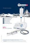
Motorsystem
MD 10
Made in Switzerland
Bedienungsanleitung
Operation manual
Mode d'emploi
Istruzione d'uso
Instrucciones de uso
D
GB
F
I
E
Nr. 31820
www.nouvag.com
NOUVAG
®
NOUVAG AG
Herzlichen Glückwunsch zum Kauf eines Produktes der Firma NOUVAG AG. Wir freuen uns, dass
Sie sich für ein NOUVAG Erzeugnis entschieden haben und danken Ihnen für Ihr entgegengebrachtes Vertrauen.
Diese Bedienungsanleitung wird Sie mit dem Gerät und seinen Eigenschaften vertraut machen,
damit eine möglichst lange und problemlose Funktion gewährleistet werden kann.
Im Anhang finden Sie die Konformitätserklärung und unsere autorisierten Servicestellen.
•
Bitte lesen Sie diese Anleitung vor Inbetriebnahme aufmerksam durch!
Congratulations on your purchase of a NOUVAG AG product. Thank you for the confidence shown
in our products.
Please consult the instruction manual for the use and maintenance of the device in order to ensure
that it will function properly and efficiently for many years.
You will find the conformity statement and list of authorized service representatives attached.
•
Before operating, please read instructions carefully!
Félicitations vous venez d’acheter un produit NOUVAG AG. Merci de la confiance que vous
montrez en nos produits.
Merci de consulter le mode d’emploi pour l’utilisation et l’entretien de cet appareil de manière à
vous assurer qu’il fonctionnera correctement et efficacement pendant de nombreuses années.
Vous trouverez ci-joint les déclarations de conformité et la liste des agents agréés pour l’entretien.
•
Lire soigneusement les instructions avant utilisation!
Ci congratuliamo con Lei per l’acquisto di un prodotto NOUVAG AG e le auguriamo un susseguirsi
di successi professionali.
Questo manuale l’aiuterà a conoscere meglio l’apparecchiatura e le sue caratteristiche. Contiene
indicazioni utili che le assicureranno un funzionamento efficiente ed una lunga durata.
Qui allegato troverete la dichiarazione di conformità e la lista dei rivenditori autorizzati.
•
Prego leggere attentamente le istruzione d’uso prima di mettere in funzionamento!
Muchas gracias por la compra de un producto NOUVAG AG.
Felicidades por la elección y la confianza depositada en nuestros productos.
Para garantizar una función duradera y eficiente del aparato, por favor consultar el manual de
instrucciones.
El Certificado de Conformidad y la lista de Centros de Servicio se encuentran en el apéndice.
•
Por favor leer las instrucciones detenidamente antes de poner en marcha el aparato!
NOUVAG AG
MD 10
INHALTSVERZEICHNIS
1
Produktebeschreibung
1.1
1.2
1.3
1.4
1.5
Einsatz und Funktionsweise
Technische Daten
Umgebungsbedingungen für Betrieb
Umgebungsbedingungen für Transport und Lagerung
Gerätesymbole
2
2
2
2
2
2
2
Sicherheitshinweise
3
3
Geräteübersicht
4
4
Gerätevorbereitung
4
4.1
4.2
4.3
5
Bedienung
5.1
5.2
5.3
5.4
5.5
5.6
5.7
5.8
6
Montage Internkühlung
Montage Externkühlung
Montage der kombinierten Kühlung
Gerät einschalten
Bedienpanel
Einstellen der Drehzahl
Einstellen der Pumpleistung
Steuerung mit Vario-Fusspedal
Drehmomentbegrenzung AL (Automatic Limiter)
Drehmomentbegrenzung AS (Automatic Stopper)
Speichern der Einstellungen
Reinigung, Desinfektion und Sterilisation
6.1
6.2
6.3
6.4
Steuergerät und Fusspedal
Elektronikmotor 31ESS
Schlauchset Nr. 1706
Y-Verbinder
5
5
5
6
6
6
7
7
7
8
8
8
9
9
9
9
9
7
Störungen und Fehlersuche
10
8
Ersatzteilliste mit Bestellnummern
10
9
Hinweis zur Entsorgung
10
No. 31820 22/07
1
MD 10
NOUVAG AG
1 Produktebeschreibung
1.1 Einsatz und Funktionsweise
Der mikroprozessorgesteuerte MD10 wird in der Implantologie und Mikrochirurgie eingesetzt. Das Gerät
ist für das Bohren, Schrauben und Sägen im Knochen konzipiert. Der MD10 besitzt eine
Schlauchpumpe für die Kühlung der rotierenden Instrumente zur Vermeidung von
Gewebeschädigungen.
1.2 Technische Daten
Spannung: ..........................................................umschaltbar: 230 V∼/ 50-60 Hz oder 115 V∼/ 50-60 Hz
Leistung: ........................................................................................................................................130 VA
Anwendungsteil: ............................................................................................................................ Typ BF
Schutzart: .....................................................................................................................................Klasse 1
Drehzahl Motor: ........................................................................................................... 500 - 40´000 Upm
Max. Motordrehmoment: .............................................................................................................. 10 Ncm
Masse (HxBxT): ........................................................................................................120 x 190 x 250 mm
Gewicht netto: .....................................................................................................................................3 kg
1.3 Umgebungsbedingungen für
Betrieb
1.4 Umgebungsbedingungen für
Transport und Lagerung
Rel. Luftfeuchtigkeit: ................... max. 80%
Temperatur: .............................. 10 bis 40°C
Luftdruck:..........................800 bis 1060hPa
Rel. Luftfeuchtigkeit:......................... max. 90%
Temperatur:..................................... 0 bis 60°C
Luftdruck:............................... 700 bis 1060hPa
1.5 Gerätesymbole
: Achtung Begleitpapiere beachten
: Anwendungsteil des Typs BF
IP68
: Fusspedal wasserdicht
KB 1min on / : Kurzzeitbetrieb des Elektronikmotors:
3min off
1min ein, 3min aus
1275 : EU-Konformitätszeichen
: Zertifiziert von Canadian Standards
Associaton (CSA) für Kanada und
USA
: Alte Elektro- und
Elektronikgeräte müssen
getrennt entsorgt werden und
dürfen nicht dem Hausmüll
zugeführt werden.
: Autoklavierbar bis max. 134°C
2
No. 31820 22/07
NOUVAG AG
MD 10
2 Sicherheitshinweise
Ihre Sicherheit, die Ihres Teams und selbstverständlich die Sicherheit Ihrer Patienten ist uns ein grosses
Anliegen. Daher ist es unerlässlich, die folgenden Hinweise zu beachten:
Grundsätzlich:
•
Der MD10 darf nur von fachkundigem und geschultem Personal bedient
werden!
•
Die Verwendung von Fremdprodukten liegt in der Verantwortung des
Betreibers!
•
Reparaturen dürfen nur
vorgenommen werden!
•
Unsachgemässer Gebrauch und Reparatur des Gerätes, sowie die
Nichteinhaltung
unserer
Anweisungen,
entbindet
uns
von
jeder
Garantieleistung oder anderen Ansprüchen!
durch
autorisierte
NOUVAG
Service-Techniker
Bei der Anwendung:
•
Das Gerät wird nicht steril ausgeliefert!
•
Hand- und Winkelstücke dürfen nur im Stillstand des Elektronikmotors
aufgesetzt werden!
•
Nie in laufende oder
Verletzungsgefahr!
•
Nie während des Laufens oder Auslaufens die Spannmechanismen der Handoder Winkelstücke betätigen! Instrumente können beschädigt werden.
No. 31820 22/07
auslaufende
Bohrer
oder
Fräser
greifen,
da
3
MD 10
NOUVAG AG
3 Geräteübersicht
10
19
11
18
17
9
1
2
13
12
3
4
5
14
7
8
15
6
16
20
21
1.
2.
3.
4.
5.
6.
7.
8.
9.
10.
11.
Steuergerät MD10
Bedienpanel
Hauptschalter Gerät “ON / OFF“
Fusspedalbuchse “FOOT SWITCH”
Motorbuchse “MOTOR“
Elektronikmotor
Handstückablage
Winkelstück (nicht im Lieferumfang)
Schlauchset
Kühlflüssigkeit
Stativ für Spüllösung
12.
13.
14.
15.
16.
17.
18.
19.
20.
21.
Schlauchpumpe
Netzkabel
Fusspedal (IP68)
Schalter für Pumpe und Forw/Rev
Trittplatte
Quetschrolle
Tropfenkammer
Entlüftungsventil
Netzbuchse
Spannungsumschalter
115V/230Vinbetriebnahme
4 Gerätevorbereitung
1)
2)
3)
4)
Stativ für Kühlflüssigkeit in Stativhalter einstecken.
Motorstecker des Elektronikmotors in Motorbuchse “MOTOR“ stecken.
Fusspedalstecker in Fusspedalbuchse „FOOT SWITCH“ stecken.
Winkelstück auf Elektronikmotor aufstecken.
→ Siehe Bilderreihe rechts:
5)
Rändelmutter von Schlauchpumpe lösen und mit Schraube nach
hinten schwenken.
6)
Pumpendeckel nach oben aufschwenken.
7)
Einlagebeispiel entfernen.
8)
Schlauchset für Kühlflüssigkeit einsetzen.
9)
Pumpendeckel wieder nach unten zuschwenken
und mit Rändelmutter verschliessen.
4
No. 31820 22/07
NOUVAG AG
MD 10
Beim Einlegen des Schlauchset sind die Pfeilmarkierungen auf dem
Pumpengehäuse zu beachten. Sie geben die Richtung des Kühlflüssigkeitsflusses
an!
10) Einstechdorn oberhalb der Tropfenkammer in Kühlmittelflasche einstecken und Flasche am Stativ
einhängen.
11) Quetschrolle öffnen.
12) Entlüftungsventil unterhalb der Tropfkammer öffnen.
13) Steuergerät mittels Netzstecker an Steckdose anschliessen.
Vergewissern Sie sich am Spannungsumschalter auf der Rückseite, dass die
Betriebsspannung der Netzspannung entspricht!
230
4.1 Montage Internkühlung
3
1)
Kühlrohr (1) in Schlauchende stecken.
2)
Clip (2 & 3) am Kühlschlauch befestigen.
3)
Kühlrohr in Winkelstück stecken.
4)
Clip am Winkelstück und am Motorkabel befestigen.
5)
Bei Bedarf weitere Clip am Motorkabel befestigen.
2
1
4.2 Montage Externkühlung
1)
Clip (1 & 2) an Kühlschlauch befestigen.
2)
Schlauchstück mit Kühlrohr (3) verbinden.
3)
Clip am Winkelstück und am Motorkabel befestigen.
4)
Bei Bedarf weitere Clip am Motorkabel befestigen.
2
3
1
4.3 Montage der kombinierten Kühlung
1)
Y-Verbinder (1) am Schlauchende befestigen.
2)
Am Y-Verbinder zwei 16cm-Schlauchstücke (2)
anbringen.
3)
Erstes Schlauchstück mit Kühlrohr (3) für Internkühlung
verbinden.
4)
Clip (4 & 5) an Kühlschlauch befestigen.
5)
Kühlschlauch mit Clip an Winkelstück und an
Motorkabel befestigen.
6)
Kühlrohr in Winkelstück stecken.
7)
Zweites Schlauchstück mit externer Kühlung verbinden.
8)
Bei Bedarf weitere Clip am Motorkabel befestigen.
No. 31820 22/07
5
3
4
1
2
5
MD 10
NOUVAG AG
5 Bedienung
5.1 Gerät einschalten
Mit dem grünen Hauptschalter “ON/OFF“ wird das Steuergerät ein- respektiv ausgeschaltet.
5.2 Bedienpanel
16:1
A) Display:
32:1
Drehzahl, Drehmoment oder Pumpengeschwindigkeit wird angezeigt
B) Übersetzungstaste “1:5” (für 1:5 Winkelstücke):
Drehzahl: 2’500 - 200’000 Upm
Drehmoment: 1, 2 Ncm
C) Übersetzungstaste “1:1” (für 1:1 Winkelstücke):
Drehzahl: 500 - 40’000 Upm
Drehmoment: 1, 2, 3, 4, 5, 6, 7, 8, 9, 10 Ncm
D) Untersetzungstaste “16:1” (für 16:1 Winkelstücke):
Drehzahl: 30 – 2’500 Upm
Drehmoment: 5, 7, 10, 12, 15, 17, 20, 25, 30, 35 Ncm
E) Untersetzungstaste “32:1” (für 32:1 Winkelstücke):
Drehzahl: 15 - 1’250 Upm
Drehmoment: 10, 15, 20, 25, 30, 35, 40, 45, 50, 55 Ncm
F)
Fixtaste “SAW” (für Nouvag Sägen):
Drehzahl: 14’000 Upm
Drehmoment: 10 Ncm
G) Fixtaste “MUCO” (für Nouvag Mucotom):
Drehzahl: 8’000 Upm
Drehmoment: 10 Ncm
H) Taste “ATC SET”:
Nach Drücken der Taste “ATC SET” kann Drehmomentbegrenzung AL oder AS eingestellt werden.
I)
Taste “PUMP SET”:
Nach Drücken der Taste “PUMP SET” kann Pumpengeschwindigkeit eingestellt werden.
J)
Wenn bei Taste B) bis I) grüne Lampe leuchtet, ist Taste aktiv.
Taste “DOWN”:
Werte von Drehzahl, Drehmoment und Pumpe können verkleinert werden.
K) Taste “UP”:
Werte von Drehzahl, Drehmoment und Pumpe können erhöht werden.
L)
Lampe “MOTOR ON”:
Grüne Lampe signalisiert, dass Elektronikmotor eingeschaltet ist.
M) Lampe “REVERSE MODE”:
Grüne Lampe signalisiert, dass Elektronikmotor rückwärts läuft. In Betrieb ertönt zusätzlich ein
akustisches Signal.
6
No. 31820 22/07
NOUVAG AG
MD 10
5.3 Einstellen der Drehzahl
1)
Entsprechende Unter- oder Übersetzungstaste drücken (z.B. Taste “32:1” für Winkelstück 32:1)
2)
Mit Tasten “UP” oder “DOWN” gewünschte Drehzahl einstellen.
Mit den Tasten “SAW“ (für Nouvag-Sägen) und “MUCO“ (für Nouvag-Mucotom) werden entsprechende
Fixwerte der Drehzahlen und der Drehmomente eingestellt.
Gewählte Unter- oder Übersetzung auf dem Bedienpanel muss mit Unter- oder
Übersetzung des Winkelstücks übereinstimmen, da sonst Gerät eine falsche
Drehzahl anzeigt.
5.4 Einstellen der Pumpleistung
Die Förderleistung der Schlauchpumpe kann in Stufen von 1 bis 10 verändert werden.
1)
Taste “PUMP SET” drücken und auf Display erscheint Pumpenauswahl (z.B. [P
6])
2)
Mit Tasten “UP” und “DOWN” kann gewünschte Pumpengeschwindigkeit eingestellt werden.
3)
Taste “PUMP SET” drücken oder 3s warten bis Drehzahlanzeige automatisch im Display erscheint.
5.5 Steuerung mit Vario-Fusspedal
Taste “PUMP“:
Pumpe wird ein- respektiv ausgeschaltet (Siehe Lampe “PUMP SET“)
Taste “FORW / REV“:
Einstellen der Drehrichtung des Motors (Siehe Lampe “REVERSE MODE“)
Trittplatte:
Mit der Trittplatte des Fusspedals kann der Pumpvorgang aktiviert und die Drehzahl des Motors variabel
gesteuert werden:
Trittplatte ...
... nicht gedrückt
Motor:
Motor aus
... leicht runtergedrückt
Motor läuft langsam
... ganz runtergedrückt
Motor läuft maximal (Drehzahl
wie an Steuergerät eingestellt)
Pumpe:
Pumpe aus
Pumpe ein, falls “PUMP“
gedrückt (Drehzahl wie an
Steuergerät eingestellt)
Pumpe ein, falls “PUMP“
gedrückt (Drehzahl wie an
Steuergerät eingestellt)
Das Gerät kann aus Sicherheitsgründen nur mit Fusspedal bedient werden.
No. 31820 22/07
7
MD 10
NOUVAG AG
5.6 Drehmomentbegrenzung AL (Automatic Limiter)
Die Funktion AL begrenzt das Drehmoment am Instrument. Für Knochenbohrungen wird im AL-Modus
gearbeitet, damit der Elektronikmotor genügend Kraft entwickelt um das Instrument auch im harten
Knochen noch anzutreiben. Die Drehzahl am Instrument bleibt bis zum Erreichen des gewählten
Drehmomentes konstant. Wird die Belastung auf das Instrument über das gewählte Limit erhöht,
verringert sich die Drehzahl bis zum Stillstand. Die Kraft am Instrument bleibt erhalten. Wird die
Belastung wieder verkleinert, erhöht sich die Drehzahl wieder.
Die Werte sind immer in Ncm angegeben (Bsp. [AL 20] → Werkzeug wird mit max. 20 Ncm belastet).
Einstellen des AL:
1)
Taste “ATC SET” drücken. Im Display erscheint die Drehmomentauswahl, z.B. [AL
2)
Mit den Tasten “UP” und “DOWN” können Sie den gewünschten Drehmomentwert einstellen.
3)
Taste “ATC SET” drücken oder 3s warten bis Drehzahlanzeige automatisch am Display erscheint.
20].
Falls im Display [AS.....] erscheint:
Taste “DOWN” drücken bis [AL.....] im Display erscheint.
Wenn AL-Modus aktiv ist, leuchtet grüne Lampe bei Taste “ATC SET” nicht.
5.7 Drehmomentbegrenzung AS (Automatic Stopper)
Die Funktion AS begrenzt das Drehmoment am Instrument. Der AS-Modus arbeitet wie ein
Drehmomentschlüssel beim Festziehen von Implantaten und Deckschrauben. Sobald das
voreingestellte Drehmoment erreicht ist, stoppt der Elektronikmotor sofort und auf dem Display
erscheint das eingestellte Drehmoment z.B. [AS
40]. Der Elektronikmotor erzeugt keine Kraft mehr.
Um den Elektronikmotor wieder zu starten, muss die Trittplatte losgelassen und wieder neu gedrückt
werden.
Die Werte sind immer in Ncm angegeben (Bsp. [AS 20] → Werkzeug wird mit max. 20 Ncm belastet).
Funktion AS ist nur bei Untersetzungen 16:1 und 32:1 und den Drehzahlen bis 150
Upm bzw. 75 Upm aktiv! Bei anderen Unter- und Übersetzungen oder Drehzahlen
kann nur mit Funktion AL gearbeitet werden.
Einstellen des AS:
1)
Taste Untersetzung “16:1” oder “32:1” drücken.
2)
Drehzahl zwischen 30 und 150 Upm bzw. 15 und 75 Upm einstellen.
3)
Taste “ATC SET” drücken. Im Display erscheint Drehmomentauswahl (z.B. [AS
4)
Mit Tasten “UP” und “DOWN” kann gewünschter Drehmomentwert eingestellt werden.
5)
Taste “ATC SET” drücken oder 3s warten bis Drehzahlanzeige automatisch im Display erscheint.
20]).
Falls im Display [AL.....] erscheint:
Taste “UP” drücken bis [AS.....] im Display erscheint.
Wenn AS-Modus aktiv ist, leuchtet grüne Lampe bei Taste “ATC SET”.
5.8 Speichern der Einstellungen
Beim Einschalten des Gerätes erscheinen automatisch die Einstellungen des letzten Gebrauchs.
8
No. 31820 22/07
NOUVAG AG
MD 10
6 Reinigung, Desinfektion und Sterilisation
Für die Pflege des Materials sind insbesondere folgende wichtige Punkte zu beachten:
•
Reinigung, Desinfektion und Sterilisation nach jeder Behandlung durchführen!
•
Keine lösungsmittelhaltigen Reinigungsmittel verwenden!
•
Material immer im Klarsichtbeutel verpackt autoklavieren!
•
Sterilisationsverpackungen dürfen nur bis zu 80% gefüllt sein!
•
Material bei maximal 134°C autoklavieren!
•
Falls sterilisiertes Material nicht sofort zum Einsatz kommt, sollte es auf der
Verpackung mit Sterilindikator und Sterildatum beschriftet werden!
6.1 Steuergerät und Fusspedal
Steuergerät und Fusspedal kommen mit dem Patienten nicht in Berührung:
Nur äusserliche Wischdesinfektion mit mikrobiologisch geprüften Flächendesinfektionsmitteln oder
80%-igem Äthyl-Alkohol verwenden. Die Frontplatte der Steuereinheit ist entsprechend abgedichtet und
abwaschbar.
6.2 Elektronikmotor 31ESS
•
Motorenkabel nicht knicken, da sonst Kabelbruch möglich!
•
Elektronikmotor nicht mit Druckluft reinigen!
•
Autoklavieren ohne Klarsichtbeutel kann den Elektronikmotor beschädigen!
1)
• Den Elektronikmotor nach dem Autoklavieren abkühlen lassen!
Motor mitsamt Kabel und Stecker von Rückständen befreien und reinigen. Dazu sauberer,
befeuchteter Lappen mit Reinigungs- oder Desinfektionsmittel zum Abwischen verwenden.
2)
Motor mit Nou-Clean - Spray durchsprühen (Handhabung siehe Sprayaufschrift!).
3)
Motor in Sterilgut-Einzelverpackung (siehe DIN 58953) verpacken.
4)
Eingepackten Motor inkl. Kabel bei max. 134°C .
Bei Autoklaven ohne Nachvakuum muss Trocknungsphase erfolgen. Motor im Beutel mindestens 1
Stunde bei Raumtemperatur, mit Papierseite nach oben, trocknen lassen.
6.3 Schlauchset Nr. 1706
Einwegschlauchset 1706 kann nicht sterilisiert werden!
6.4 Y-Verbinder
Um Auskristallisieren der Kochsalzlösung zu vermeiden, sollte Y-Verbinder nach
Gebrauch mit destilliertem Wasser durchgespült werden!
1)
Y-Verbinder mit angeschlossenen Winkelstück ca. 20s mit destilliertem Wasser durchspülen.
2)
Schläuche vom Y-Verbinder entfernen.
3)
Y-Verbinder in einen Klarsichtbeutel verpacken und bei max. 134°C autoklavieren.
No. 31820 22/07
9
MD 10
NOUVAG AG
7 Störungen und Fehlersuche
Störung:
Gerät funktioniert
nicht
Kein Kühlmittel am
Instrument
Ursache:
Behebung:
Steuergerät nicht
eingeschaltet
Falsche Betriebsspannung
Netzverbindung nicht
hergestellt
Schlauchpumpe nicht
eingeschaltet
Hauptschalter “ON/OFF“
auf ”ON”-Position schalten
Netzspannung überprüfen
Steuergerät an Stromnetz
anschliessen
Schlauchpumpe
einschalten
Schlauchset richtig
einspannen (Richtung
beachten!)
Schlauchset falsch
eingespannt
Schlauchset verklebt /
verkrustet
Flasche von
Kochsalzlösung nicht
belüftet
Schlauchset tropft
Auf Display erscheint
[ HOT ]
Elektronikmotor ist
überhitzt
Fusspedal funktioniert Fusspedal nicht
angeschlossen
nicht
Fehlbedienung
Hinweis
Betriebsanl.:
3 Geräteübersicht
1.2 Technische Daten
3 Geräteübersicht
5.5 Steuerung mit VarioFusspedal
4 Gerätevorbereitung
Schlauchset austauschen
21 inbetriebnahme
Belüftungsfilter bei
Tropfkammer öffnen
3 Geräteübersicht
Schlauchset austauschen
Gerät ausschalten, 10 min
warten, Gerät wieder
einschalten
Fusspedalkabel
Steuergerät anschliessen
Betriebsanleitung
nachlesen
4 Gerätevorbereitung
4 Gerätevorbereitung
5.5 Steuerung mit VarioFusspedal
Kann ein Fehler nicht behoben werden, wenden Sie sich bitte an den Lieferanten oder an eine
autorisierte Servicestelle. Die Anschriften sind auf der letzten Seite der Bedienungsanleitung zu finden.
8 Ersatzteilliste mit Bestellnummern
Zubehör
Art.-Nr
Clip Set Motorenkabel: 10 Stk. ...........................................................................................................1873
Clip Set Winkelstück: 3 Stk. ...............................................................................................................1881
Schlauch zu Y-Verbinder; 16cm .........................................................................................................1773
Schlauchset; Einweg, steril, 2m..........................................................................................................1706
Y-Verbinder.........................................................................................................................................1777
Kühlflüssigkeit, 0.9% NaCl, 1l.............................................................................................................1707
Nou-Clean; Pflege- / Reinigungsspray ...............................................................................................1984
Sprayrohr Aufsatz E-Kupplung, für Chirurgieinstrumente...................................................................1958
Sprayrohr Aufsatz, für Elektronikmotor...............................................................................................1942
Für Bestellungen anderer Teile steht Ihnen unser Kundendienst gerne zur Verfügung.
9 Hinweis zur Entsorgung
Bei der Entsorgung von Gerät, Gerätbestandteilen und Zubehör müssen die erlassenen Vorschriften
des Gesetzgebers befolgt werden.
Im Sinne des Umweltschutzes können Altgeräte an den Händler oder den Hersteller zurückgegeben
werden.
10
No. 31820 22/07
NOUVAG AG
MD 10
TABLE OF CONTENTS
1
Description
1.1
1.2
1.3
1.4
1.5
Operations and functions
Technical Data
Operating Environment
Transport and Storage Environment
Symbols
2
2
2
2
2
2
2
Safety measures
3
3
System Assembly
4
4
Operation
4
4.1
4.2
4.3
4.4
5
Operation
5.1
5.2
5.3
5.4
5.5
5.6
5.7
5.8
6
Set-up
Tubing assembly-Internal irrigation
Tubing assembly–External irrigation
Tubing assembly-combined
Starting the MD 10
Keyboard
Setting the revolutionsSetting the output of the irrigation pump
Operation with vario-pedal
Setting the torque limiter AL (Automatic Limiter)
Setting the torque limiter AS (Automatic Stopper)
Memory
Disinfection, Cleaning and Sterilization
6.1
6.2
6.3
6.4
Control unit and foot control
Electronicmotor 31ESS
Tubing set Nr. 1706
Y-Connector
4
5
5
5
6
6
6
6
7
7
8
8
8
9
9
9
9
9
7
Troubleshooting
10
8
Replacement parts and numbers
10
9
Disposal
10
No. 31820 22/07
1
MD 10
NOUVAG AG
1 Description
1.1 Operations and functions
The MD10 is used in Implantology and microsurgery. The unit is designed for drilling, screwing and
sawing. A built-in irrigation system minimizes the heat generation of the rotating instruments in order to
reduce infections that can cause tissue damage.
1.2 Technical Data
Voltage: .................................................................... changeable: 230 V∼/ 50-60 Hz or115 V∼/ 50-60 Hz
Power: ........................................................................................................................................... 130 VA
Application of part: ...................................................................................................................... Type BF
Protection level: ............................................................................................................................ Class 1
Motor speed: ................................................................................................................ 500 – 40,000 rpm
Max. torque: ................................................................................................................................. 10 Ncm
Dimensions (WxHxD): ............................................................................................. 120 x 190 x 250 mm
Net weight: ......................................................................................................................................... 3 kg
1.3 Operating Environment
1.4 Transport and Storage Environment
Relative Humidity: ....................... max. 80%
Temperature: ..............................10 to 40°C
Pressure: ........................... 800 to 1060hPa
Relative Humidity:............................. max. 90%
Temperature:..................................... 0 to 60°C
Pressure: .................................700 to 1060hPa
1.5 Symbols
: Attention accompanying
documents
: Application of part type BF
1275 : Conforms to EU standards
: Certified by Canadian Standards
Association (CSA) for Canada and
USA
IP68
: Watertight foot control
KB 1min on / : Electronic motor short operation:
1min on 3min off
3min off
: Old electrical and electronic
equipment must be disposed
separately and may not be
included in regular domestic
waste.
: Autoclavable at max. 134°C
2
No. 31820 22/07
NOUVAG AG
MD 10
2 Safety measures
Your safety, the safety of your team, and, it goes without saying, the safety of your patients is for Nouvag
AG the first priority. It is therefore vital that the following measures be strictly observed:
Important:
•
The MD 10 should be operated by qualified personnel only!
•
Responsibility for the use of sub-units, accessories, parts or assemblies from
other manufacturers rests solely with the user!
•
Repairs are to be carried out by authorized NOUVAG service technicians only!
•
Nouvag AG cannot be held liable for any malfunction of the MD 10, or
performance failure and/or its designed or desired utility, nor can Nouvag AG
be held liable for any injuries to persons or animals, in any case when the MD
10 is miss-used or not operated, applied or maintained in strict accordance with
the user/owner instructions set out in the operating manual. In the event of any
doubt or question, the user is to contact Nouvag AG or its lawful representative
for clarification or assistance!
In Operation:
•
The unit will be not supplied in a sterile condition!
•
Do not attach the handpiece and contra angle while the motor is running!
•
To avoid danger, do not grab running burr or drill!
•
To avoid damage of the instruments, do not handle the clamping mechanism,
while the handpiece or contra angle are in operation!
No. 31820 22/07
3
MD 10
NOUVAG AG
3 System Assembly
10
19
11
18
17
9
1
2
13
12
3
4
5
14
7
8
15
6
16
20
21
1.
2.
3.
4.
5.
6.
7.
8.
9.
10.
11.
Control unit
Keyboard panel
Mains switch “ON / OFF“
Pedal socket “FOOT SWITCH”
Motor socket “MOTOR“
Electronicmotor
Handpiece support
Contra angle (not included)
Tubing set
Cooling fluid flask
Hanger rod for liquid flask
12.
13.
14.
15.
16.
17.
18.
19.
20.
21.
Pump
Mains cable
Foot control (IP68)
Switch for Pump and Forw/Rev
Foot plate
Tube clamp
Drip chamber
Air valve
Mains cable socket
Voltage switch
4 Operation
4.1 Set-up
1)
2)
3)
4)
Insert solution hanger in support on panel of control unit.
Insert electronicmotor plug into motor socket “MOTOR“.
Insert pedal plug into pedal socket„FOOT SWITCH“.
Attach contra angle to electronicmotor.
→ see row of pictures right:
5)
Loosen and lift screw latch from pump lid.
6)
Open lid forward.
7)
Remove demonstration tube.
8)
Insert tube set.
9)
Close pump lid, lower screw latch and close.
4
No. 31820 22/07
NOUVAG AG
MD 10
Insure that „pressure“ tube runs to irrigation needle, and „suction“ tube runs to
solution bottle!
10) Insert tube needle and hang cooling flask on hanger rod.
11) Open tube clamp.
12) Open air valve of the drip chamber.
13) Connect the mains cable into the electrical outlet.
Check for correct operation voltage and verify mains voltage output!
230
4.2 Tubing assembly-Internal irrigation
3
1)
Insert internal irrigation needle (1) into the end of the
tubing.
2)
Attach clip (2 & 3) to irrigation tubing.
3)
Insert irrigation needle into contra angle.
4)
Attach clip to contra angle and to motor cable.
5)
When necessary, attach additional clips to motor cable.
2
1
4.3 Tubing assembly–External irrigation
1)
Attach clip (1 & 2) to irrigation tubing.
2)
Connect piece of tubing to irrigation needle (3).
3)
Attach clip to contra angle and to motor cable.
4)
When necessary, attach additional clips to motor
cable.
2
3
1
4.4 Tubing assembly-combined
1)
Attach Y-connector (1) to the end of the tubing.
2)
Attach two 16cm pieces of tubing (2) to Y-connector.
3)
For internal irrigation, connect first tubing piece to
irrigation needle (3).
4)
Attach clips (4 & 5) to irrigation tubing.
5)
Attach irrigation tubing with clip to contra angle and to
motor cable.
6)
Insert irrigation needle into contra angle.
7)
Connect second tubing piece with external irrigation.
8)
When necessary, attach additional clips to motor cable.
No. 31820 22/07
5
3
4
1
2
5
MD 10
NOUVAG AG
5 Operation
5.1 Starting the MD 10
Press green “ON/OFF“ switch.
5.2 Keyboard
16:1
A) Display:
32:1
Indication of the revolutions (speed), torque or pump speed.
B) Multiplying key “1:5” (for contra angle 1:5):
Speed: 2,500 – 200,000 rpm
Torque: 1, 2 Ncm
C) Multiplying key “1:1” (for contra angle 1:1):
Speed: 500 – 40,000 rpm
Torque: 1, 2, 3, 4, 5, 6, 7, 8, 9, 10 Ncm
D) Reduction “16:1” (for contra angle 16:1):
Speed: 30 – 2,500 rpm
Torque: 5, 7, 10, 12, 15, 17, 20, 25, 30, 35 Ncm
E) Reduction “32:1” (for contra angle 32:1):
Speed: 15 – 1,250 rpm
Torque: 10, 15, 20, 25, 30, 35, 40, 45, 50, 55 Ncm
F)
Fixed key “SAW” (for Nouvag saws):
Speed: 14,000 rpm
Torque: 10 Ncm
G) Fixed key “MUCO” (for Nouvag Mucotome):
Speed: 8,000 rpm
Torque: 10 Ncm
H) Key “ATC SET”:
Press key “ATC SET” to adjust the torque limiter AL or AS.
I)
Key “PUMP SET”:
Press key “PUMP SET” to adjust the pump speed.
J)
The green light on key B) to I) illuminates, when the key is activated.
Taste “DOWN”:
To decrease the speed, torque and pump.
K) Taste “UP”:
To increase the speed, torque and pump.
L)
Light “MOTOR ON”:
The green light indicates that the electronicmotor is switched on.
M) Light “REVERSE MODE”:
The green light indicates that the electronicmotor operates in reverse and a warning tone will sound.
5.3 Setting the revolutions1)
6
Press the appropriate reduction or multiplying key (for example key “32:1” for contra angle 32:1).
No. 31820 22/07
NOUVAG AG
2)
MD 10
Press keys “UP” or “DOWN” to select the desired speed.
With the keys “SAW“ (for Nouvag-saws) and “MUCO“ (for Nouvag-Mucotome) the corresponding fixed
speed and torque values can be adjusted.
The reduction or multiplication on the keyboard panel has to be according to the
reduction or multiplication of the contra angle, otherwise the device will indicate
an incorrect revolution.
5.4 Setting the output of the irrigation pump
The output of the irrigation pump can be selected from 1 to 10 levels.
1)
Press key “PUMP SET” and in the display appears for example, pump selection [P
6].
2)
Press keys “UP” and “DOWN” to select the desired pump speed.
3)
Press key “PUMP SET” or wait 3 seconds until the revolutions appear automatically in the display.
5.5 Operation with vario-pedal
Key “PUMP“:
To turn the pump on and off (see light “PUMP SET“)
Key “FORW / REV“:
To adjust the direction of rotation of the motor (see light “REVERSE MODE“)
Foot plate:
Push foot plate down to start pump action and to vary the motor speed.
Foot plate ...
... not pressed
Motor:
Motor off
... lightly pressed
Motor runs slowly
... fully pressed
Motor speed max.(as indicated
by setting on control unit)
Pump:
Pump off
Pump on, if “PUMP“ is pressed
(speed as indicated by setting on
control unit)
Pump on, if “PUMP“ is pressed
(speed as indicated by setting on
control unit)
Caution: for safety use the unit with foot control only!
No. 31820 22/07
7
MD 10
NOUVAG AG
5.6 Setting the torque limiter AL (Automatic Limiter)
The automatic limiter (AL) limits the torque level applied to the instrument. The AL-modus is used for
drilling into the bone, in order to allow the electronicmotor to develop enough power, so the instrument
can have a good drive in hard bones, as well. The speed in the instrument is hold constantly until the
selected setting is reached. If the load in the instrument over the adjusted limiter increases, the speed
will drop to zero. The power in the instrument remains. If the load in the instrument over the adjusted
limiter decreases, the speed will increase again.
All torque values are shown in Ncm (for example a setting of [AL 20] → indicates that the instrument
can be loaded to maximum of max. 20 Ncm before rotations stops).
Adjusting the AL:
1)
Press the “ATC” key. In the display appears the torque mode set (for example [AL 20]).
2)
Pressing the keys “UP” and “DOWN” will increase and decrease the torque level respectively.
3)
Press “ATC SET” or wait for 3 seconds until the speed appears automatically in the display.
If the display says [AS.....] :
Press key “DOWN” until [AL.....] appears in the display.
When the AL-Modus is activated, the green light on the “ATC SET” key does not
illuminate.
5.7 Setting the torque limiter AS (Automatic Stopper)
The function AS limits the torque in the instrument. The AS operates like a torque wrench for tightening
implants and abutments. The electronicmotor stops immediately when the preselected torque is
achieved and in the display appears the selected torque, for example [AS
40]. The electronicmotor
does not generate power anymore. To restart the electronicmotor, release briefly the foot plate and
press it again.
All torque values are shown in Ncm (for example a setting of [AS 20] → indicates that the instrument
can be loaded to maximum of max. 20 Ncm.
The function AS is activated in the reductions 16:1 and 32:1 only, and up to 150
rpm and 75 rpm respectively! For other reduction or multiplication use function
AL.
Setting the AS:
1)
Press reduction key “16:1” or “32:1”.
2)
Adjust the speed between 30 and 150 rpm and 15 and 75 rpm respectively.
3)
Press key “ATC SET” . In the display appears the torque selection (for example [AS
4)
Press keys “UP” and “DOWN” to select the desired torque values.
5)
Press the key “ATC SET” or wait for 3 seconds until the revolutions appear automatically in the
display.
20]).
If the display says [AL.....]:
Press key “UP” until [AS.....] appears in the display.
When the AS-Modus is activated, the green light on the “ATC SET” illuminates.
5.8 Memory
Once programmed, the preselected speed, torque and value setting will remain stored in memory, even
when the motor is turned off.
8
No. 31820 22/07
NOUVAG AG
MD 10
6 Disinfection, Cleaning and Sterilization
Please pay attention to the following important points for the maintenance of the material:
•
Clean, disinfect and sterilize the device and components after each use.
•
Do not use dissolving agents for cleaning.
•
Autoclave material in transparent packaging.
•
Do not fill the sterilization bag more than 80%.
•
Autoclave material at maximum 134°C.
•
Sterilized material should be stored and tagged with sterilization date,
6.1 Control unit and foot control
The control unit and the foot control do not come in contact with patients. Clean the surface of the unit
only, do not use harsh cleaners or solvents for cleaning. Use 80% ethyl alcohol or microbiologically
effective disinfectants. The control unit face is sealed and washable.
6.2 Electronicmotor 31ESS
•
To avoid breakage, do not bend motor cable!
•
Do not clean the electronicmotor with compressed air!
•
Clean, disinfect and sterilize the electronicmotor after each use!
•
Autoclaving the electronicmotor without packing it into a transparent bag may
seriously damage it!
•
After autoclaving, allow electronicmotor to dry for one hour at room
temperature.
1)
The electronicmotor, cable and plug should be cleaned after each use to prevent the build up of
deposits and debris that can destroy it, if not removed. Wipe it with a clean cloth dampened with
disinfectant solution.
2)
Spray the motor interior with Nou-Clean - spray.( See spray can instructions).
3)
Pack Motor in transparent bag (see DIN 58953).
4)
After packing motor and cable, autoclave it at maximum 134°C .
After autoclaving, allow electronicmotor to dry for one hour at room temperature.
6.3 Tubing set Nr. 1706
Disposable tubing set Nr. 1706can not be sterilized!
6.4 Y-Connector
After use, flush the saline residue out of the Y-Connector with distilled water for
approximately 20 seconds with distilled water!
1)
Flush the Y-Connector with connected contra angle with distilled water for approximately 20
seconds.
2)
Remove the tubings from the Y-Connector.
3)
Pack the Y-Connecotor in a transparent bag and sterilize the pack in an autoclave at max. 134°C.
No. 31820 22/07
9
MD 10
NOUVAG AG
7 Troubleshooting
Problem:
Device does not
operate at all
Cause:
Solution:
Control unit not turned on
Wrong operating voltage
Mains not connected
No coolant in the
instrument
Irrigation pump not turned
ON
Tubing set not mounted
properly
Tubing set is glued
together/coated with
deposit
Turn main switch
“ON/OFF“ON
Check mains voltage
output
Connect mains to control
unit
Turn the irrigation pump
ON
Mount tubing properly (pay
attention to direction!)
Exchange tubing
Cooling fluid flask
Open air filter on drip
chamber
Exchange tubing set
Turn off the unit, wait for
Electronicmotor is getting
10 minutes, turn on the
too hot
unit again
Plug foot control into
Foot control not connected
control unit
not ventilated
Tubing set is dripping
[ HOT ] appears in
display
Foot control fails to
function
Refer:operating
Manual:
3 System Assembly
1.2 Technical Data
3 System Assembly
5.5 Operation with vario-
pedal
4.1 Set-up
4 Operation
3 System Assembly
4.1 Set-up
4.1 Set-up
In the event a problem cannot be solved, contact dealer or authorized service technicians, as listed on
the last page of your Operating Instruction Manual.
8 Replacement parts and numbers
Accesories
Art.-Nr
Clip Set motor cable (10 pcs.) ............................................................................................................1873
Clip Set contra angle (3 pcs.) .............................................................................................................1881
Tubing (16cm) for Y-Connector ..........................................................................................................1773
Disposable tubing set, standard, sterile..............................................................................................1706
Y-Connetor .........................................................................................................................................1777
Cooling fluid flask, 0.9% NaCl, 1l........................................................................................................1707
Nou-Clean; Cleaning spray.................................................................................................................1984
Spray nozzle attachment E-coupling, for surgery instruments ...........................................................1958
Spray nozzle attachment, for electronicmotor ....................................................................................1942
For ordering other parts, our customer service personnel are pleased to assist
9 Disposal
Disposal of device, components and accessories must strictly conform to local laws and regulations as
set out by the relevant authorities.
With regard to the preservation of the environment old equipment may be returned to the distributor or
manufacturer.
10
No. 31820 22/07
NOUVAG AG
MD 10
TABLE DES MATIERES
1
Description
1.1
1.2
1.3
1.4
1.5
Utilisation et fonctionnement
Données techniques
Environnement d’utilisation
Environnent de transport et stockage
Symboles
2
2
2
2
2
2
2
Mesures de sécurité
3
3
Schéma du système
4
4
Mise en service
4
4.1
4.2
4.3
4.4
5
Fonctionnement
5.1
5.2
5.3
5.4
5.5
5.6
5.7
5.8
6
Mise en marche
Branchement tubulure – Irrigation interne
Branchement tubulure – Irrigation externe
Branchement tubulure – Double irrigation
Mise en marche du MD 10
Clavier
Programmer le nombre de tours
Programmer le débit de la pompe d’irrigation
Utilisation avec la pédale du variateur
Programmer la limite du couple AL (Limitation automatique)
Programmer la limite du couple AS (Arrêt automatique)
Mémoire
Désinfection, nettoyage et stérilisation
6.1
6.2
6.3
6.4
Unité et pédale de contrôle
Micro moteur 31ESS
Tubulure réf. 1706
Connecteur en Y
4
5
5
5
6
6
6
7
7
7
8
8
8
9
9
9
9
9
7
Dépannage
10
8
Références des pièces de rechange
10
9
Mise au rebut
10
No. 31820 22/07
1
MD 10
NOUVAG AG
1 Description
1.1 Utilisation et fonctionnement
Le MD10 est utilisé en implantologie et en microchirurgie. L’unité est destinée au forage, vissage et
sciage dans l’os. Un système d’irrigation interne minimise la production de chaleur des instruments
rotatifs de manière à réduire le risque de lésion tissulaire.
1.2 Données techniques
Voltage : ................................................................. changeable : 230 V∼/ 50-60 Hz ou115 V∼/ 50-60 Hz
Tension : ....................................................................................................................................... 130 VA
Application de pièce : .................................................................................................................. Type BF
Niveau de protection : ................................................................................................................. Classe 1
Vitesse moteur : ........................................................................................................ 500 – 40,000 tr/min
Couple maxi : .............................................................................................................................. 10 N/cm
Dimensions (LxHxP) : .............................................................................................. 120 x 190 x 250 mm
Poids net : .......................................................................................................................................... 3 kg
1.3 Environnement d’utilisation
1.4
Environnent
stockage
de
transport
et
Humidité relative : ........................maxi 80%
Température : .............................10 à 40°C
Pression :............................ 800 à 1060hPa
Humidité relative :............................. maxi 90%
Température :..................................... 0 à 60°C
Pression : .................................700 à 1060hPa
1.5 Symboles
: Attention lire les documents joints
: Application de pièce type BF
IP68
: Pédale de contrôle étanche
KB 1min on / : Micro moteur courte utilisation :
1mn de marche, pour 3mn
3min off
d’arrêt
1275 : Conforme aux normes de l’UE
: Certifié par la Canadian Standards
Association (CSA) pour le Canada
et les USA
: De vieux appareils électriques et
d'électronique doivent être
éliminés séparé et ne peuvent
pas être amenés aux ordures
ménagères.
: Stérilisable à 134°C maxi
2
No. 31820 22/07
NOUVAG AG
MD 10
2 Mesures de sécurité
Votre sécurité, la sécurité de votre équipe et, il va sans dire la sécurité de vos patients est pour Nouvag
AG la première des priorités. Il est donc vital que les mesures suivantes soient strictement respectées :
Important :
•
Le MD 10 doit être utilisé uniquement par du personnel qualifié !
•
Toute responsabilité pour l’utilisation de sous ensembles, accessoires, pièces
ou ensembles d’autres fabricants est entièrement celle de l’utilisateur !
•
Les réparations doivent être effectuées uniquement par des techniciens agréés
NOUVAG !
•
L’utilisation de cet appareil à des fins non conformes, ou son mauvais entretien
annule la garantie et décharge la firme Nouvag AG de toute responsabilité. En
cas de doute ou de question, l’utilisateur peut contacter Nouvag AG ou ses
représentants légaux pour clarification ou assistance !
En fonctionnement :
•
L’unité n’est pas fournie stérile !
•
Ne pas fixer la pièce à main et le contre angle pendant que le moteur
fonctionne!
•
Pour éviter tout danger, ne pas toucher fraise ou foret en marche !
•
Pour éviter tout endommagement des instruments, ne pas actionner le
mécanisme de serrage pendant que la pièce à main ou le contre angle
fonctionnent !
No. 31820 22/07
3
MD 10
NOUVAG AG
3 Schéma du système
10
19
11
18
17
9
1
2
13
12
3
4
5
14
7
8
15
6
16
20
21
1.
2.
3.
4.
5.
6.
7.
8.
9.
10.
11.
Unité de contrôle
Clavier
Interrupteur principal «ON / OFF»
Prise pédale «FOOT SWITCH»
Prise moteur «MOTOR»
Pièce à main
Support pièce à main
Contre angle (non compris)
Ensemble tubulure
Flacon de liquide de refroidissement
Tige de suspension pour flacon
12.
13.
14.
15.
16.
17.
18.
19.
20.
21.
Pompe
Câble secteur
Pédale de contrôle (IP68)
Interrupteur pour pompe et avant/arrière
Support pied
Attache tuyau
Compte-gouttes
Purgeur d’air
Prise câble secteur
Bouton voltage
4 Mise en service
4.1 Mise en marche
1)
2)
3)
4)
Mettre la tige de suspension sur le caisson de l’unité de contrôle.
Brancher la fiche du micro moteur dans la prise «MOTOR».
Brancher la fiche de la pédale dans la prise «FOOT SWITCH».
Brancher le contre angle au micro moteur.
→ voir photos de droite :
5)
Desserrer et lever la vis de serrage du couvercle de la pompe.
6)
Ouvrir le couvercle vers l’avant.
7)
Oter le tuyau de démonstration.
8)
Fixer le jeu de tubulure.
9)
Fermer le couvercle de la pompe, baisser la vis de serrage et fermer.
4
No. 31820 22/07
NOUVAG AG
MD 10
Lors de l’installation de la tubulure, respecter le sens des flèches sur le capot de
la pompe. Elles donnent le sens du liquide d’irrigation !
10) Insérer l’aiguille de la tubulure et suspendre le liquide de refroidissement sur la tige.
11) Ouvrir la pince du tuyau.
12) Ouvrir le purgeur d’air de la chambre du compte-gouttes.
13) Brancher le câble principal sur l’électricité.
Vérifier le bon voltage d’utilisation et contrôler le voltage du secteur !
230
4.2 Branchement tubulure – Irrigation interne
3
1)
Insérer l’aiguille d’irrigation interne (1) dans l’extrémité
du tuyau.
2)
Fixer les attaches (2 & 3) au tuyau d’irrigation.
3)
Mettre l’aiguille d’irrigation dans le contre angle.
4)
Fixer l’attache au contre angle et au câble du moteur.
5)
Si nécessaire, mettre des attaches supplémentaires sur
le câble du moteur.
2
1
4.3 Branchement tubulure – Irrigation externe
1)
Fixer les attaches (1 & 2) au tuyau d’irrigation.
2)
Brancher le tuyau à l’aiguille d’irrigation (3).
3)
Fixer l’attache au contre angle et au câble du moteur.
4)
Si nécessaire, mettre des attaches supplémentaires
sur le câble du moteur.
2
3
1
4.4 Branchement tubulure – Double irrigation
1)
Fixer le connecteur Y (1) à l’extrémité de la tubulure.
2)
Fixer 2 tubulures de 16cm (2) au connecteur en Y.
3)
Pour l’irrigation interne, commencer par brancher la
première tubulure à l’aiguille d’irrigation (3).
4)
Fixer les attaches (4 & 5) au tuyau d’irrigation.
5)
Fixer le tuyau d’irrigation au contre angle et au câble du
moteur avec des attaches.
6)
Mettre l’aiguille d’irrigation dans le contre angle.
7)
Brancher la seconde tubulure à l’irrigation externe.
8)
Si nécessaire, mettre des attaches supplémentaires
sur le câble du moteur.
No. 31820 22/07
5
3
4
1
2
5
MD 10
NOUVAG AG
5 Fonctionnement
5.1 Mise en marche du MD 10
Appuyer sur l’interrupteur vert «ON/OFF».
5.2 Clavier
16:1
32:1
A) Affichage: Compte-tours (vitesse), puissance du couple ou débit de la pompe.
B) Touche multiplicatrice «1:5» (pour contre angle 1:5):
Vitesse : 2,500 – 200,000 tr/min
Couple: 1, 2 N/cm
C) Touche multiplicatrice «1:1» (pour contre angle 1:1):
Vitesse: 500 – 40,000 tr/min
Couple: 1, 2, 3, 4, 5, 6, 7, 8, 9, 10 N/cm
D) Réduction «16:1» (pour contre angle 16:1):
Vitesse: 30 – 2,500 tr/min
Couple: 5, 7, 10, 12, 15, 17, 20, 25, 30, 35 N/cm
E) Réduction «32:1» (pour contre angle 32:1):
Vitesse: 15 – 1,250 tr/min
Couple: 10, 15, 20, 25, 30, 35, 40, 45, 50, 55 N/cm
F)
Touche fixe «SAW» (pour scie Nouvag) :
Vitesse: 14,000 tr/min
Couple: 10 N/cm
G) Touche fixe «MUCO» (pour Mucotome Nouvag) :
Vitesse: 8,000 tr/min
Couple: 10 N/cm
H) Touche «ATC SET»:
Appuyer sur «ATC SET» pour régler la limite du couple AL ou AS.
I)
Touche «PUMP SET»:
Appuyer sur «PUMP SET» pour régler le débit de la pompe.
J)
La lumière verte sur les touches de B) à I) s’allume lorsque les touches sont
activées.
Touche «DOWN» :
Pour baisser la vitesse, le couple et le débit de la pompe.
K) Touche «UP» :
Pour augmenter la vitesse, le couple et le débit de la pompe.
L)
Lumière «MOTOR ON» :
La lumière verte indique que le micro moteur est en marche.
M) Lumière «REVERSE MODE» :
La lumière verte indique que le micro moteur fonctionne en sens inverse et un signal sonore
retentira.
6
No. 31820 22/07
NOUVAG AG
MD 10
5.3 Programmer le nombre de tours
1)
Appuyer sur la touche de réduction ou de multiplication appropriée (par exemple la touche «32:1»
pour un contre angle 32:1).
2)
Appuyer sur «UP» ou «DOWN» pour choisir la vitesse souhaitée.
Avec les touches «SAW» (pour les scies Nouvag) et «MUCO» (pour le Mucotome Nouvag) la vitesse
fixée correspondante et les valeurs de rotation peuvent être réglées.
La réduction ou la multiplication sur le clavier doivent être en accord avec la
réduction ou la multiplication du contre angle, sinon l’appareil indiquera un
nombre de tours inexact.
5.4 Programmer le débit de la pompe d’irrigation
Le niveau du débit de la pompe d’irrigation peut être choisi de 1 à 10.
1)
Appuyer sur la touche «PUMP SET» et le choix de la pompe s’affiche, par exemple [P
6].
2)
Appuyer sur les touches «UP» et «DOWN» pour choisir le débit souhaité.
3)
Appuyer sur la touche «PUMP SET» ou attendre 3 secondes jusqu’à ce que le nombre de tours
s’affiche automatiquement.
5.5 Utilisation avec la pédale du variateur
Touche «PUMP» :
Pour mettre en marche ou arrêter la pompe (voir lumière «PUMP SET»)
Touche «FORW / REV» :
Pour régler le sens de rotation du moteur (voir lumière «REVERSE MODE»)
Pédale de contrôle :
Appuyer sur la pédale pour démarrer la pompe et varier la vitesse du moteur.
Pédale...
... pas enfoncée
... légèrement enfoncée
... entièrement enfoncée
Moteur :
Moteur arrêté
Pompe :
Pompe arrêtée
Pompe en marche, si «PUMP»
Le moteur tourne doucement
enfoncé (débit programmé sur
l’unité de contrôle)
Vitesse maxi du moteur (comme Pompe en marche, si «PUMP»
programmé sur l’unité de
enfoncé (débit programmé sur
contrôle)
l’unité de contrôle)
Attention: pour votre sécurité, utiliser l’unité uniquement avec la pédale.
No. 31820 22/07
7
MD 10
NOUVAG AG
5.6 Programmer la limite du couple AL (Limitation automatique)
La limitation automatique (AL) limite le niveau du couple appliqué à l’instrument. Le mode AL est utilisé
pour forer dans l’os, cela permet au micro moteur de développer assez de puissance pour que
l’instrument ait une bonne coupe, également dans l’os dur. La vitesse de l’instrument est maintenue
constante jusqu’à ce que le réglage souhaité soit atteint. Si la charge de l’instrument augmente audessus de la limite réglée, la vitesse descendra à zéro. L’instrument reste en marche. Si la charge de
l’instrument baisse, la vitesse augmentera de nouveau.
Toutes les valeurs de rotation sont indiquées en N/cm (par exemple un réglage de [AL 20] → indique
que l’instrument peut atteindre au maximum 20 N/cm avant que la rotation ne s’arrête).
Réglage de AL :
1)
Appuyer sur la touche «ATC». Le réglage du mode couple s’affiche (par exemple [AL 20]).
2)
En appuyant sur «UP» et «DOWN» le niveau du couple augmentera et baissera respectivement.
3)
Appuyer sur «ATC SET» ou attendre 3 secondes jusqu’à ce que la vitesse s’affiche
automatiquement.
Si l’affichage indique [AS.....] :
Appuyer sur «DOWN» jusqu’à ce que [AL.....] s’affiche.
Lorsque le mode AL est activé, la lumière verte sur la touche «ATC SET» est
éteinte.
5.7 Programmer la limite du couple AS (Arrêt automatique)
La fonction AS limite le couple de l’instrument. AS agit comme une clef dynamométrique, serrant les
implants et piliers. Le micro moteur arrête immédiatement lorsque le couple choisi est atteint et que
l’écran affiche le couple choisi, par exemple [AS
40]. Le micro moteur ne génère plus aucune
puissance. Pour redémarrer le micro moteur, relâcher brièvement la pédale et appuyer de nouveau.
Toutes les valeurs du couple sont indiquées en N/cm (par exemple un réglage à [AS 20] → indique
que l’instrument peut atteindre 20 N/cm maximum.
La fonction AS est activée pour les réductions 16:1 et 32:1 uniquement et jusqu’à
150 tr/min et 75 tr/min respectivement ! Pour tout autre réduction ou multiplication
utiliser la fonction AL.
Réglage de AS :
1)
Appuyer sur la touche de réduction «16:1» ou «32:1».
2)
Régler la vitesse entre 30 et 150 tr/min et 15 et 75 tr/min respectivement.
3)
Appuyer sur «ATC SET». Le choix du couple apparaît sur l’écran (exemple [AS
4)
Appuyer sur «UP» et «DOWN» pour choisir les valeurs du couple désirées.
5)
Appuyer sur «ATC SET» ou attendre 3 secondes jusqu’à ce que le nombre de tours s’affiche
automatiquement.
20]).
Si l’affichage indique [AL.....] :
Appuyer sur «UP» jusqu’à ce que [AS.....] apparaisse.
Lorsque le mode AS est activé, la lumière verte sur «ATC SET» est allumée.
5.8 Mémoire
Lors du branchement de l’appareil, apparaissent automatiquement les réglages faits lors de la dernière
utilisation.
8
No. 31820 22/07
NOUVAG AG
MD 10
6 Désinfection, nettoyage et stérilisation
Merci de faire attention aux points suivants, très importants pour l’entretien du matériel :
•
Nettoyer, désinfecter et stériliser l’appareil et les composants après chaque
utilisation!
•
Ne pas utiliser d’agent dissolvant pour le nettoyage!
•
Passer le matériel à l’autoclave dans un sac transparent!
•
Ne pas remplir le sac de stérilisation à plus de 80%!
•
Passer à l’autoclave à 134°C maximum!
•
Le matériel stérilisé doit être stocké et étiqueté avec la date de stérilisation!
6.1 Unité et pédale de contrôle
L’unité de contrôle et la pédale ne sont pas en contact avec les patients. Nettoyer uniquement la surface
de l’unité, ne pas utiliser de nettoyant abrasif ou solvant pour le nettoyage. Utiliser 80% d’alcool
éthylique ou des désinfectants antimicrobiens. Le devant de l’unité de contrôle est étanche et lavable.
6.2 Micro moteur 31ESS
•
Pour éviter la casse, ne pas plier le câble du moteur!
•
Ne pas nettoyer le micro moteur à l’air comprimé!
•
Nettoyer, désinfecter et stériliser le micro moteur après chaque utilisation!
•
Passer le micro moteur à l’autoclave sans qu’il soit emballé dans un sac
transparent peut sérieusement l’endommager!
•
Après l’autoclave, laisser le micro moteur sécher pendant une heure à
température ambiante!
1)
Le micro moteur, le câble et la prise doivent être nettoyés après chaque utilisation pour éviter
l’accumulation de dépôts et débris pouvant les endommager. Essuyer avec un chiffon propre
humidifié de solution désinfectante.
2)
Vaporiser l’intérieur du moteur de Nou-Clean spray (voir instructions sur l’emballage).
3)
Emballer le moteur dans un sac transparent (voir DIN 58953).
4)
Après avoir emballé le moteur et le câble, passer à l’autoclave à 134°C maximum . Ensuite laisser
sécher le micro moteur pendant une heure à température ambiante, côté papier sur le dessus.
6.3 Tubulure réf. 1706
Tubulure jetable réf. 1706 non stérilisable!
6.4 Connecteur en Y
Après usage, rincer la solution saline contenue dans le connecteur en Y avec de
l’eau distillée pendant environ 20 secondes!
1)
Rincer le connecteur en Y avec le contre angle sous l’eau distillée pendant environ 20 secondes.
2)
Oter les tubulures du connecteur en Y.
3)
Mettre le connecteur en Y dans un sac en plastique transparent et stériliser dans l’autoclave à
134°C maxi.
No. 31820 22/07
9
MD 10
NOUVAG AG
7 Dépannage
Problème :
Cause :
L’appareil ne
L’unité de contrôle n’est
fonctionne pas du tout pas en marche
Mauvais voltage
Secteur non branché
Pas de liquide de
refroidissement dans
l’instrument
Solution :
Mettre l’interrupteur
principal sur «ON»
Vérifier le voltage du
secteur
Brancher l’unité de
contrôle au secteur
La pompe d’irrigation n’est Mettre la pompe
pas en marche
d’irrigation sur «ON»
Référence: mode
d’emploi :
3 Schéma du système
1.2 Données techniques
3 Schéma du système
5.5 Utilisation avec la
pédale
La tubulure n’est pas
correctement montée
Monter la tubulure
correctement (attention
aux instructions!)
4.1 Mise en march
La tubulure est collée
ensemble/couverte de
dépôt
Changer de tubulure
4 Mise en service
Le flacon de liquide de
refroidissement n’est
pas ventilé
Ouvrir le filtre à air du
compte-gouttes
3 Schéma du système
La tubulure goutte
[ HOT ] s’affiche sur
l’écran
Le micro moteur est trop
chaud
La pédale de contrôle
ne fonctionne pas
La pédale n’est pas
branchée
Changer de tubulure
Arrêter l’unité, attendre 10
minutes, remettre l’unité
en marche
Brancher la pédale à
l’unité de contrôle
4.1 Mise en march
4.1 Mise en march
Si le problème ne peut être résolu, contacter votre revendeur ou les services techniques agréés, dont la
liste se trouve sur la dernière page de votre mode d’emploi.
8 Références des pièces de rechange
Accessoires
Article réf.
Assortiment d’attaches câble du moteur (10 pièces) .........................................................................1873
Assortiment d’attaches contre angle (3 pièces)..................................................................................1881
Tubulure (16cm) pour connecteur en Y..............................................................................................1773
Tubulure jetable, standard, stérile ......................................................................................................1706
Connecteur en Y.................................................................................................................................1777
Liquide de refroidissement, 0.9% NaCl, 1l .........................................................................................1707
Nou-Clean; Spray de nettoyage..........................................................................................................1984
Attache pour canule de spray, fixation en E, pour instruments chirurgicaux......................................1958
Attache pour canule de spray, pour micro moteur..............................................................................1942
Pour la commande d’autres pièces, notre service clientèle sera heureux de vous aider.
9 Mise au rebut
La mise au rebut d’appareils, composants et accessoires doit être strictement conforme aux lois et
règles locales comme fixées par les autorités compétentes.
Dans le sens de la protection de l'environnement, de vieux appareils peuvent être rendus au
commerçant ou au fabricant Service
10
No. 31820 22/07
NOUVAG AG
MD 10
Indice
1
Descrizione
1.1
1.2
1.3
1.4
1.5
Funzionamento
Specifiche tecniche
Condizione di operatività
Condizione di trasporto e conservazione
Simboli
2
2
2
2
2
2
2
Misure di sicurezza
3
3
Assemblaggio del sistema
4
4
Installazione e funzionamento del sistema
4
4.1
4.2
4.3
4.4
5
Preparazione dell’apparecchiatura
Irrigazione interna
Irrigazione esterna
Irrigazione combinata
Messa in funzione
5.1
5.2
5.3
5.4
5.5
5.6
5.7
5.8
6
Messa in funzione dell’apparecchiatura
Panello di comando
Impostazione della velocità
Impostazione della velocità della pompa d'irrigazione
Funzionamento con comando a pedale
Impostazione del limitatore di torque AL (Automatic Limiter)
Torque AS (Automatic Stopper)
Memoria
Disinfezione, pulizia e sterilizazione
6.1
6.2
6.3
6.4
Unità di controllo e pedale
Motore elettronico 31 ESS
Deflussori No. 1706
Connettore Y
4
5
5
5
6
6
6
7
7
7
8
8
8
9
9
9
9
9
7
Analisi e guasti
10
8
Pezzi di ricambioo e loro codici
10
9
Eliminazione
10
No. 31820 22/07
1
MD 10
NOUVAG AG
1 Descrizione
1.1 Funzionamento
L’ MD10 viene utilizzato in implantologia ed in microchirurgia per preparare letti implantari, avvitare
componenti ed eseguire tagli o fori nell’osso. L’ MD10 è dotato di un motore ad induzione ed utilizza un
microprocessore che ne controlla tutte le funzioni e gestisce sia il pannello di controllo, che il display
digitale. Il sistema di raffreddamento a pompa peristaltica, incorporato, riduce la possibilità che un
surriscaldamento locale provochi danni tissutali o necrosi asettica.
1.2 Specifiche tecniche
Tensione d’alimentazione: ......................................... cambiabile: 230 V∼/ 50-60 Hz o 115 V∼/ 50-60 Hz
Potenza assorbita: .........................................................................................................................130 VA
Tipo di apparecchio : ....................................................................................................................Tipo BF
Sistema di protezione: ................................................................................................................ Classe 1
Velocità del motore: ...................................................................................................... 500 – 40,000 rpm
Torque massimo del motore: ........................................................................................................ 10 Ncm
Dimensioni: LxAxP: ..................................................................................................120 x 190 x 250 mm
Peso netto: ..........................................................................................................................................3 kg
1.3 Condizione di operatività
1.4
Condizione di trasporto e
conservazione
Umidità relativa: ......................... max. 80%
Temperatura: .............................. 10 - 40°C
Pressione: ...........................800 - 1060hPa
Umidità relativa: .............................. max. 90%
Temperatura: ..................................... 0 - 60°C
Pressione: .................................700 -1060hPa
1.5 Simboli
prestare la massima attenzione a
queste informazioni
Apparecchio tipo BF
1275 Marchio di conformità della
Unione Europea
Certificato dalla Canadian
Standards Association (CSA)
2
Autoclavabile, massimo a
134°C
IP68
KB 1min on /
3min off
Pedale a tenuta stagna
Modalità di funzionamento del
motore elettronico: 1 Min. sotto
carico, 3 Min. non sotto carico.
: Apparecchi elettrici ed
elettronici vecchi devono
essere smaltiti separamene e
non vanno gettati nei rifiuti
urbani.
No. 31820 22/07
NOUVAG AG
MD 10
2 Misure di sicurezza
La Sua sicurezza, la sicurezza della Suo team operatorio, e, come ovvio, la sicurezza dei Suoi pazienti
rappresentano per la Nouvag AG, una priorità, è quindi fondamentale che le istruzioni seguenti
vengano strettamente osservate dall’utilizzatore.
Importante:
•
L’ MD 10 deve essere utilizzato solo da operatori qualificati e specializzati.
•
La responsabilità dell’utilizzo di parti e pezzi di ricambi non originali ricade
totalmente sull’utilizzatore.
•
Eventuali riparazioni devono essere eseguite solo presso centri tecnici
autorizzati Nouvag.
•
Nel caso in cui l’ MD 10 non venga utilizzato, mantenuto, comandato o usato
secondo quanto specificamente indicato nelle istruzioni elencate nel presente
manuale operativo, la Nouvag AG non potrà in alcun caso essere ritenuta
responsabile per qualunque malfunzionamento dell’apparecchiatura o dei suoi
componenti e, inoltre, non potrà essere tenuta responsabile in nessun caso per
qualsiasi danno fisico a persone o animali che dovesse verificarsi nell’ipotesi
suddetta.
Funzionamento:
•
I componenti dell’apparecchiatura non vengono forniti sterili.
•
Per evitare danni agli strumenti, non inserire il manipolo, mentre il motore è in
funzione.
•
Per evitare pericoli o danni, non sganciare i manipoli mentre il motore è in
funzionamento.
•
Per evitare pericoli o danni, non toccare con le mani le frese o gli strumenti da
taglio mentre il motore è in funzione.
No. 31820 22/07
3
MD 10
NOUVAG AG
3 Assemblaggio del sistema
10
19
11
18
17
9
1
2
13
12
3
4
5
14
7
8
15
6
16
20
21
1. Unità di controllo MD10
2. Panello di controllo
3. Interruttore di accensione “ON / OFF“
4. Connettore del pedale di comando
5. Connettore del motore elettronico
6. Motore elettronico
7. Supporto per manipolo
8. Manipolo contrangolo (non incluso)
9. Tubo del deflussore
10. Contenitore della soluzione fisiologica
11. Asta di sostengo
12.
13.
14.
15.
16.
17.
18.
19.
20.
21.
Pompa peristaltica
Cavo di alimentazione
Pedaliera di comando (IP68)
Interruttore di comando pompa ed inversione
direzione motore
Piastra del pedale
Blocco dell’irrigazione
Camera di gocciolamento
Valvola di sfiato
Presa del cavo di alimentazione
Commutatore di tensione 115V/230V
4 Installazione e funzionamento del sistema
4.1 Preparazione dell’apparecchiatura
1)
Inserire il connettore del cavo di alimentazione nella apposita presa
sul retro dell’Unità di controllo.
2) Inserire l’asta di sostegno nell’apposito foro.
3) Inserire il connettore del micromotore nella presa sul frontale
dell’unità di controllo.
4) Inserire il connettore del pedale nella sua presa sul frontale
dell’unità di controllo.
5) Inserire il manipolo sul micromotore controllando che scatti e
si blocchi nell’apposta sede.
6) Allentare il dado zigrinato della pompa e tirarlo in avanti, liberando
il di fermo coperchio di protezione.
7) Sollevare il coperchio di protezione della pompa.
8) Inserire la parte spessa del deflussore nella pompa peristaltica rispettando
i versi indicati sulla stessa.
9) Riportare il coperchio della pompa nella posizione iniziale, reinserire la vite
di serraggio verticalmente e stringere il dado zigrinato.
10) Ove necessario, ruotare manualmente il rotore della pompa ponendolo
verticalmente, per consentire una più facile chiusura del coperchio.
4
No. 31820 22/07
NOUVAG AG
MD 10
Accertarsi del senso di inserimento del deflussore nella pompa rispettando i versi,
di aspirazione e mandata, indicati.
11) Inserire la spina di plastica nel flacone della fisiologica ed appende quest’ultimo all’asta di
sostegno.
12) Aprire la rotella di blocco.
13) Aprire la valvola di sfiato.
Assicurarsi della corrispondenza fra il voltaggio impostato e quello di rete.
230
14) Azionare l’interruttore di accensione verificando che lo stesso si illumini.
4.2 Irrigazione interna
1)
Inserire la parte più spessa dell’ago per l’irrigazione
interna (1) nell’estremità del deflussore.
2)
Fissare le clip (2 e 3) al tubicino del deflussore.
3)
Inserire la parte sottile dell’ago per l’irrigazione interna
(1) nel foro posto nella parte posteriore della testa del
contrangolo.
4)
Fissare le clip al contrangolo ed al cavo del motore.
5)
Se necessario, fissare con altre clip il deflussore al
cavo del motore.
3
2
1
4.3 Irrigazione esterna
1)
Fissare le clip (1 e 2) al tubicino del deflussore.
2)
Collegare l’estremità del deflussore alla apposita
cannula di irrigazione(3) posta sotto la testina del
contrangolo.
3)
Fissare le clip al contrangolo e al cavo del motore.
4)
Se necessario, fissare altre clip il deflussore al cavo del
motore.
2
3
1
4.4 Irrigazione combinata
1)
Inserire il connettore a Y (1) all’estremità del deflussore.
2)
Collegare due pezzetti di tubi (2)al connettore a Y (1).
3)
Infilare la parte più spessa dell’ago per l’irrigazione
interna nell’estremità di uno dei due tubicini (2) e
inserirne, poi, la parte sottile nel foro posto nella parte
posteriore della testa del contrangolo.
4)
Fissare le clip (4 e 5)al contrangolo ed al cavo del
motore.
5)
Fissare con clip del deflussore al contrangolo ed al cavo
del motore.
6)
Inserire l’altro pezzetto di tubo d’irrigazione nella
apposita cannula posta sotto la testina del contrangolo.
7)
Se necessario, fissare con altre clip il deflussore al cavo
del motore.
No. 31820 22/07
5
3
4
1
2
5
MD 10
NOUVAG AG
5 Messa in funzione
5.1 Messa in funzione dell’apparecchiatura
Accendere l’unità di controllo tramite l’interruttore principale posto sul frontale.
5.2 Panello di comando
16:1
32:1
A) Display: Indicazione della velocità operativa, del torque e della velocità della pompa
B) Tasto moltiplicatore “1:5” (per contrangolo 1:5):
Velocità: 2,500 – 200,000 g/m;
Torque: 1, 2 Ncm
C) Tasto standard “1:1” (per contrangolo 1:1):
Velocità: 500 – 40,000 g/m;
Torque: 1, 2, 3, 4, 5, 6, 7, 8, 9, 10 Ncm
D) Tasto di riduttore “16:1” (per contrangolo 16:1):
Velocità: 30 – 2,500 g/m;
Torque: 5, 7, 10, 12, 15, 17, 20, 25, 30, 35 Ncm
E) Tasto di riduttore “32:1” (per contrangolo 32:1):
Velocità: 15 – 1,250 g/m;
Torque: 10, 15, 20, 25, 30, 35, 40, 45, 50, 55 Ncm
F)
Tasto fisso “SAW” (per sega chirurgiche Nouvag):
Velocità: 14,000 g/m
Torque: 10 Ncm
G) Tasto fisso “MUCO” (per Mucotomo Nouvag):
Velocità: 8,’000 g/m
Torque: 10 Ncm
H) Tasto “ATC SET”:
Premendo il tasto “ATC SET“, può essere programmato il limitatore di torque nelle
funzioni AL o AS.
I)
Tasto “PUMP SET”:
Il tasto “PUMP SET“permette di programmare velocità, e quindi la portata, della pompa
d’irrigazione.
J)
Il led verde dei tasti B) fino a I) si illumina quando il tasto viene selezionato.
Tasto “DOWN”:
Utilizzabile per diminuire la velocità, torque ed il flusso della pompa.
K) Taste “UP”:
Utilizzabile per aumentare la velocità, torque ed il flusso della pompa.
L)
Spia “MOTOR ON”:
Il led verde acceso indica, che il motore elettronico é in funzione.
M) Indicatore luminoso “REVERSE MODE”:
Il led verde acceso indica, che il motore ruota in senso contrario (Reverse).
6
No. 31820 22/07
NOUVAG AG
MD 10
5.3 Impostazione della velocità
1)
Selezionare il tasto di riduzione relativo al contrangolo in uso
contrangolo 32:1).
(per esempio “32:1“ per un
2)
Premere i tasti “UP“ o "DOWN“ per selezionare la massima velocità operativa richiesta alla fresa.
Il tasto “SAW“ (per microseghe chirurgiche Nouvag) ed il tasto “MUCO“ (per il Mucotomo Nouvag )
hanno velocità e torque fissi.
La riduzione/moltiplicazione impostata sul panello deve corrispondere alla
riduzione/moltiplicazione del contrangolo, altrimenti la velocità della fresa non
corrisponderà a quanto indicato sul display.
5.4 Impostazione della velocità della pompa d'irrigazione
La portata della pompa d’irrigazione può essere regolata da 1 a 10.
1)
Selezionare il tasto “PUMP SET”. Sul display apparirà ad esempio [P 6].
2)
Premendo il tasto “UP“ o “DOWN“ selezionare la velocità desiderata della pompa.
3)
Premere il tasto “PUMP SET“ ed attendere 3 secondi finché riapparirà automaticamente la velocità
preimpostato sul display.
5.5 Funzionamento con comando a pedale
Tasto “PUMP“:
Va utilizzato per attivare o disattivare la pompa (si illumina la spia “PUMP SET“).
Tasto “FORW / REV“:
Va utilizzato per invertire la direzione di rotazione del motore (si illumina la spia “REVERSE MODE“).
Piastra di comando del pedale:
Premendo la piastra di comando del pedale si regola la velocità del motore e contemporaneamente si
può attivare la pompa d’irrigazione.
Piastra del pedale …
…non azionata
Motore
Motore fermo
…leggermente pressata
Il motore opera lentamente alla
velocità indicata dal display
…pressata a fondo
Il motore raggiunge la massima
velocità preimpostata
Pompa
Pompa ferma
La pompa va in funzione, solo se
il tasto“PUMP“viene attivato sul
pedale (la velocità
corrisponderà al valore
preimpostato sulla unità di
controllo)
La pompa va in funzione, se il
tasto “PUMP“ viene attivato sul
pedale (velocità corrispondente
al valore preimpostato sull’ unità
di controllo)
Per motivi di sicurezza, l’unità di controllo può essere attivata solo tramite il
pedale.
No. 31820 22/07
7
MD 10
NOUVAG AG
5.6 Impostazione del limitatore di torque AL (Automatic Limiter)
La funzione AL limita il torque alla fresa. La funzione AL viene usata, nella preparazione degli alveoli
implantari, affinché il motore abbia una forza sufficiente per non bloccarsi anche in ossi particolarmente
duri.La velocità dello strumento rimane costante, finché non raggiunge il torque preselezionato. Se il
carico alla fresa aumenta troppo e supera il livello prefissato, il motore si arresta, ma rimane sotto
tensione. Quando il carico alla fresa riducendosi, rientra nei limiti, il motore si riavvia. I valori vengono
indicati sempre in Ncm (per esempio AL 20 indica che la forza limite di torque, a cui si arresta il motore,
é di 20 Ncm).
Impostare AL:
1)
Premendo il tasto “ATC SET“ il display mostrerà il livello di torque selezionato, per esempio [AL
20].
2)
Tramite i tasti “UP“ e “DOWN“ si può aumentare o diminuire il torque desiderato.
3)
Ripremere il tasto “ATC SET“ o attendere 3 secondi, il display mostrerà la velocità preselezionata
alla fresa.
Se sul display appare [AS.....]:
premere il tasto “DOWN” finché apparirà nuovamente [AL.....] sul display.
Il led verde del tasto “ATC SET“ non si illumina quando la funzione AL (Automatic
Limiter) è attivata.
5.7 Torque AS (Automatic Stopper)
La funzione AS limita il torque allo strumento. La funzione AS è utilizzabile come una !!!!chiave
dinamometrica per inserire impianti, stringere viti di copertura o pilastri (monconi implantari).
Il motore elettronico si arresta istantaneamente quando viene raggiunto il livello di AS torque
programmato che apparita sul display, per esempio [AS
40]. L’alimentazione al motore viene
automaticamente interrotta. Per riavviarlo, rilasciare e premere poi nuovamente la piastra di comando
del pedale.
I valori vengono indicati sempre in Ncm (per esempio AS 20 indica che la forza limite di torque, a cui si
arresta il motore, é di 20 Ncm)
La funzione AS é attiva con le riduzione 16:1 fino a 150 g/m e 32:1 fino a 75 g/m.
Con altre riduzioni o moltiplicatori e con altre velocità può essere operato solo
con AL .
Impostare AS
1)
Premere il tasto “16:1“ o “32:1“
2)
Selezionare la velocità tra 30 e 150 g/m (o tra 15 e 75 g/m).
3)
Premere il tasto “ATC SET“. Sul display apparirà il livello di torque preimpostato (per esempio [AS
20]).
4)
Premere i tasti “UP“ e “DOWN“ per programmare i differenti valori di torque.
5)
Ripremere il tasto “ATC SET“ o aspettare 3 secondi, il display mostrerà nuovamente la velocità
massima preselezionata.
Se sul display appare [AL.....]:
Premere il tasto “UP” finché apparirà [AS.....]sul display.
La luce verde del tasto “ATC SET“ si illumina quando la funzione AS (Automatic
Stopper) è attivata.
5.8 Memoria
Una volta programmati la velocità del motore, la portata della pompa ed il torque, i valori rimangono
memorizzati. Anche spegnendo l’apparecchio e staccando l’alimentazione elettrica.
8
No. 31820 22/07
NOUVAG AG
MD 10
6 Disinfezione, pulizia e sterilizazione
Porre la massima attenzione ai seguenti punti che riguardano la manutenzione dell’ MD10:
•
L’apparecchio e i suoi componenti devono essere sempre puliti e disinfettati
dopo ogni utilizzo. Sono autoclavabili solo i seguenti componenti: la base di
appoggio del motore (7), il motore completo di cavo e connettore (6), il
manipolo (8) e l’asta di sostegno (11).
•
Non utilizzare prodotti abrasivi o solventi.
•
Autoclavare sempre i componenti sterilizzabili, all’interno di una busta per
autoclavatura semitrasparente.
•
Non superare i 134°C durante la sterilizzazione in autoclave.
•
Annotare sempre la data di sterilizzazione sulle buste sterilizzate.
6.1 Unità di controllo e pedale
L`unita` di controllo ed il pedale non entrano a diretto contatto con il paziente. Pertanto detergere e
disinfettare le superfici delle stesse senza utilizzare prodotti abrasivi o solventi. Si consiglia l’uso di una
soluzione all`80% di alcool etilico o disinfettanti di accertata efficacia.
6.2 Motore elettronico 31 ESS
•
Non piegare il cavo del motore elettronico (6).
•
Pulire e disinfettare il motore ed il cavo dopo ogni utilizzo.
•
Non utilizzare aria compressa nella pulizia del motore.
•
1)
Estrarre il motore dall’autoclave almeno un ora prima dell’utilizzo. Lasciarlo
asciugare e condizionare a temperatura ambiente all’interno della sua busta per
autoclavatura, per almeno un’ora.
Pulire e disinfettare il motore ed il cavo dopo ogni utilizzo utilizzando un panno umido e una
soluzione disinfettante.
2)
Lubrificare il motore elettronico attraverso i due fori posti nella parte posteriore dello stesso usando
Nou-Clean Spray (seguire le istruzioni scritte sul contenitore)
3)
Inserire il motore ed il suo cavo in una busta trasparente per autoclavatura (Vedi DIN 58953)
4)
Estrarre il motore imbustato massimo 134°C
1)
Estrarre il motore dall’autoclave almeno un ora prima dell’utilizzo. Lasciarlo asciugare e
condizionare a temperatura ambiente, all’interno della sua busta per autoclavatura, per almeno
un’ora.
6.3 Deflussori No. 1706
Deflussori vengono forniti sterili, ma non sono sterilizzabili (monouso).
6.4 Connettore Y
Dopo l’utilizzo, il connettore a Y deve essere risciacquato con acqua distillata per
evitare depositi salini.
1)
Risciacquare il connettore ad Y per almeno 20 secondi al fine di evitare la formazione di depositi
salini all’interno.
2)
Inserire il connettore ad Y in una bustina trasparente per autoclavatura e sterilizzarlo in autoclave,
massimo a134°C.
No. 31820 22/07
9
MD 10
NOUVAG AG
7 Analisi e guasti
Problema:
L’unità di controllo
non funziona
Causa:
L’unità di controllo è
spenta.
Il cavo d’alimentazione
non é collegato
Tensione sbagliata
Non esce soluzione
fisiologica dal
manipolo
Soluzione:
Accendere l’unità di
controllo premendo
l’interruttore (3) “ON/OFF“
Collegare il cavo
d’alimentazione all’unità di
controllo (20)
Cambiare la tensione
Indicazione:
3 Assemblaggio del
sistema
3 Montaggio
1.2 Dati tecnici
Premere il pulsante sul
pedale
5.5 Funzionamento del
pedale
Collocare il deflussore
correttamente
4.1 Preparazione
dell'apparecchiatura
Sostituire il deflussore
4.1 Preparazione
dell'apparecchiatura
Aprire la valvola (19)
3 Assemblaggio del
sistema
Il deflussore gocciola
Cambiare il deflussore
4.1 Preparazione
dell'apparecchiatura
Sul display appare[
HOT ]
Il motore elettronico si è
surriscaldato
Spegnere l’unità di
controllo, attendere che il
motore si raffreddi.
Accendere nuovamente
l’unità di controllo
Il pedale di controllo
non funziona
Il connettore (4) del pedale
Collegare il pedale all’unità
non è inserito nella presa
di controllo
apposita (23)
Leggere il manuale
Difetto nel funzionamento
d’istruzione
La pompa non è inserita
Il deflussore non è stato
correttamente inserito
nella pompa
Il deflussore è otturato da
depositi.
Non è aperta la valvola di
sfiato sulla spina del
deflussore (19)
4.1 Preparazione
dell'apparecchiatura
5.5 Funzionamento con
pedale
Nel caso in cui un problema non può essere risolto, contattate il Vostro rivenditore Nouvag o qualunque
centro di Assistenza Nouvag.
8 Pezzi di ricambioo e loro codici
Accessori
No. Art.
Clip Set cavo del motore (10 pezzi)................................................................................................... 1873
Clip Set contrangolo (3 pezzi) ........................................................................................................... 1881
Tubo (16cm) per connettore Y........................................................................................................... 1773
Deflussore, singolo, monouso, sterile ............................................................................................... 1706
Connettore Y...................................................................................................................................... 1777
Soluzione fisiologico, 0.9% NaCl, 1lt. ................................................................................................ 1707
Nou-Clean Spray ; per pulizia e manutenzione degli strumenti ........................................................ 1984
Tappo erogatore per Spray, Tipo - E, per strumenti chirurgici ......................................................... 1958
Tappo erogatore per Spray, Tipo - E, per motore elettronico .......................................................... 1942
Per ordinare altri pezzi di ricambio, contattate il Cento di Assistenza Tecnica o Vostro
distributore Nouvag locale.
9 Eliminazione
Per l’eliminazione dell’ apparecchiatura c/o di suoi componenti e accessori, devono essere strettamente
seguite le indicazioni di legge ed regolamenti vigenti nel Vostro Paese.
Per favorire uno smaltimento ecologico, grazie alla tassa di riciclaggio anticipata (TRA), gli apparecchi
usati possono essere restituiti presso i punti di vendita o presso i centri di raccolta.
10
No. 31820 22/07
NOUVAG AG
MD 10
Contenido
1
Descripción
1.1
1.2
1.3
1.4
1.5
Funciones
Datos técnicos
Condiciones de operación
Condiciones para transporte y almacenamiento
Simbolos
2
2
2
2
2
2
2
Medidas de seguridad
3
3
Montaje
4
4
Funcionamiento
4
4.1
4.2
4.3
4.4
5
Operación
5.1
5.2
5.3
5.4
5.5
5.6
5.7
5.8
6
Preparación del aparato
Irrigación interna
Irrigación externa
Irrigación combinada
Puesta en marcha
Panel
Ajuste de las revoluciones
Regulación de la potencia de la bomba
Operación con Vario pedal
Ajuste del limitador de torque AL (Automatic Limiter)
Torque AS (Automatic Stopper)
Memoria
Desinfección, Limpieza y Esterilización
6.1
6.2
6.3
6.4
Unidad de Control y Pedal
Motor electrónico 31ESS
Juego de gomas de irrigación No. 1706
Conector Y
4
5
5
5
6
6
6
6
7
7
8
8
8
9
9
9
9
9
7
Problemas y anomalías
10
8
Partes de recambio y No. de Art.
10
9
Eliminación
10
No. 31820 22/07
1
MD 10
NOUVAG AG
1 Descripción
1.1 Funciones
El MD10 es usado en implantalogía y microcirugía. Este aparato está diseñado para taladrar, atornillar y
serrar en el hueso. Un sistema de irrigación incorporado reduce la generación de calor en los
instrumentos de rotación, evitando de esta manera infecciones que puedan dañar los tejidos.
1.2 Datos técnicos
Voltaje: ........................................................................ cambiable: 230 V∼/ 50-60 Hz ó 115 V∼/ 50-60 Hz
Potencia: ........................................................................................................................................130 VA
Aplicacion de partes: .................................................................................................................... Tipo BF
Sistema de protección: ................................................................................................................. Clase 1
Velocidad del motor: ..................................................................................................... 500 – 40,000 rpm
Torque máximo del motor: ........................................................................................................... 10 Ncm
Dimensión : ...............................................................................................................120 x 190 x 250 mm
Peso neto: ......................................................................................................................................... 3 Kg.
1.3 Condiciones de operación
1.4 Condiciones para transporte y
almacenamiento
Humedad relativa:....................... max. 80%
Temperatura: ........................10 hasta 40°C
Presión:........................ 800 hasta 1060hPa
Humedad relativa: ............................ max. 90%
Temperatura:............................... 0 hasta 60°C
Presión: ..............................700 hasta1060hPa
1.5 Simbolos
: Autoclavable hasta un Max. de
134°C
: Atención a documentos
informativos adjuntos
: Aplicación de partes tipo BF
1275 : Signo de conformidad de la Unión
Europea
: Certificado de la Asociación
Canadiense de Standards (CSA)
para Canadá y EE.UU.
2
IP68
: Pedal imperméable
KB 1min on / : Modo de operación del motor
electrónico : 1 Min. encendido, 3
3min off
Min. Apagado
: Viejos aparatos eléctricos y
electrónicos deben de ser
eliminados separadamente y no
ser incluidos en los desperdicios
domésticos
No. 31820 22/07
NOUVAG AG
MD 10
2 Medidas de seguridad
Su seguridad, la seguridad de su grupo y por supuesto la seguridad de sus pacientes, es para Nouvag
AG la mayor prioridad. Por lo tanto es indispensable acatar las siguientes medidas:
Importante:
•
El MD 10 debe ser operado solo por personal calificado y especializado.
•
El uso de otros productos, por ejemplo piezas de mano o contrángulos que no
sean de la marca Nouva AG, es resposabilidad del operador.
•
La reparaciones se deben llevar a cabo solo por los Centros de Servicios
autorizados.
•
El uso habitual o corriente así como el deterioro producido por una utilización
no apropiada o un cuidado incorrecto del aparato y sus componentes, no está
cubierto por la garantía. En lo referente al cuidado del aparato, es importante
seguir las instrucciones proporcionadas en este manual de operación o sino
contactar a Nouvag AG para más información.
Funcionamiento:
•
La unidad no se sumistra estéril.
•
El uso de otros productos, por ejemplo piezas de mano o contrángulos que no
sean de la marca NOUVAG, es resposabilidad del operador.
•
No manipular la pieza de mano o contrángulo cuando el mandril se encuentre
funcionando.
•
No manipular el mecanismo de sujeción mientras la pieza de mano o
contrángulo esten en funcionamiento.
No. 31820 22/07
3
MD 10
NOUVAG AG
3 Montaje
10
19
11
18
17
9
1
2
13
12
3
4
5
14
7
8
15
6
16
20
21
1.
2.
3.
4.
5.
6.
7.
8.
9.
10.
11.
Unidad de control MD10
Panel
Interruptor principal “ON / OFF“
Conexión del pedal “FOOT SWITCH”
Conexión del “MOTOR“
Motor electrónico
Soporte para pieza de mano
Contrángulo (no incluido)
Juego de gomas
Recipiente con solución
Varilla de suspensión para recipiente
12.
13.
14.
15.
16.
17.
18.
19.
20.
21.
Bomba
Cable
Pedal de control (IP68)
Interruptor para bomba y Forw/Rev
Plancha del pedal
Filtro de aire
Cámara de goteo
Válvula de ventilación
Enchufe
Selector de tensiòn 115V/230V
4 Funcionamiento
4.1 Preparación del aparato
1)
2)
3)
4)
Colocar la varilla de suspensión en el orificio de la consola.
Conectar el motor electrónico en el enchufe „MOTOR“.
Conectar el pedal en el enchufe „FOOT SWITCH“.
Conectar el contrángulo al motor electrónico.
5)
Aflojar y retirar la tuerca estriada.
6)
Levantar la cubierta de la bomba y deslizarla hacia atrás
7)
Extraer la goma a sustituir de la bomba.
8)
Colocar la goma de irrigación en la bomba.
9)
Volver a colocar la cubierta de la bomba en
su lugar y ajustar la tuerca estriada.
4
No. 31820 22/07
NOUVAG AG
MD 10
Asegurarse que la goma de „presión“ corra a la aguja de irrigación y la goma de
„succión“ corra al recipiente con solución.
10) Insertar la cánula de irrigación en el recipiente y colgar el recipiente en la varilla de suspensión.
11) Abrir la rueda de regulación
12) Abrir el filtro de aire estéril en la cámara de goteo
13) Conectar el cable a la toma de corriente.
Controlar el voltaje de operación y chequear la tensión de alimentación.
230
4.2 Irrigación interna
3
1)
Insertar la aguja de irrigación interna (1) al final de la
goma.
2)
Fijar el clip (2 y 3) en la goma de irrigación.
3)
Insertar la cánula de irrigación en el contrángulo.
4)
Fijar clip al contrángulo y al cable del motor.
5)
Si es necesario, fijar clips adicionales al cable del
motor.
2
1
4.3 Irrigación externa
1)
Sujetar con clips (1 y 2) la goma de irrigación.
2)
Conectar un pedazo de goma a la aguja de irrigación
(3).
3)
Fijar clip al contrángulo y al cable del motor.
4)
Si es necesario, fijar clips adicionales al cable del
motor.
2
3
1
4.4 Irrigación combinada
1)
Sujetar conector en Y (1) al final de la goma.
2)
Colocar dos piezas de 16cm-de goma (2) al conector
en Y.
3)
Para irrigación interna, conectar primer pedazo de
goma a la aguja de irrigación (3) .
4)
Fijar con clips (4 & 5) la goma de irrigación.
5)
Fijar clip al contrángulo y al cable del motor.
6)
Insetar aguja de irrigación en el contrángulo.
7)
Conectar segundo pedazo de goma con irrigación
externa.
8)
Si es necessario, fijar clips adicionales al cable del
motor.
No. 31820 22/07
5
3
4
1
2
5
MD 10
NOUVAG AG
5 Operación
5.1 Puesta en marcha
La Unidad de Control se enciende y se apaga con el Interruptor Principal “ON/OFF“.
5.2 Panel
16:1
32:1
A) Display: Indicación de las revoluciones (velocidad), torque y bomba
B) Tecla de multiplicación “1:5“,, para contrángulo 1:5
Velocidad: 2,500 – 200,000 rpm
Torque: 1, 2 Ncm
C) Tecla de multiplicación “1:1” (para contrángulo 1:1):
Velocidad: 500 – 40,000 rpm
Torque: 1, 2, 3, 4, 5, 6, 7, 8, 9, 10 Ncm
D) Tecla de reducción “16:1” (para contrángulo 16:1):
Velocidad: 30 – 2,500 rpm
Torque: 5, 7, 10, 12, 15, 17, 20, 25, 30, 35 Ncm
E) Tecla de reducción “32:1” (para contrángulo 32:1):
Velocidad: 15 – 1,250 rpm
Torque: 10, 15, 20, 25, 30, 35, 40, 45, 50, 55 Ncm
F)
Tecla fija “SAW” (para Sierras Nouvag :
Velocidad: 14,000 rpm
Torque: 10 Ncm
G) Tecla fija “MUCO” (para Mucotoma Nouvag):
Velocidad : 8,’000 rpm
Torque: 10 Ncm
H) Tecla “ATC SET”:
Después de presionar la tecla “ATC SET“, el limitador de torque AL o AS puede programarse.
I)
Tecla “PUMP SET”:
Presionando la tecla “PUMP SET“ se programma la velocidad de la bomba.
J)
La luz verde de las teclas B) hasta I) se ilumina cuando la tecla se activa.
Tecla “DOWN”:
Para reducir la velocidad, el torque y la bomba.
K) Taste “UP”:
Para aumentar la velocidad, el torque y la bomba.
L)
Lampe “MOTOR ON”:
La luz verde indica que el motor electrónico está encendido.
M) Luz “REVERSE MODE”:
La luz verde indica que el motor opera hacia atrás.
5.3 Ajuste de las revoluciones
1)
6
Presionar la tecla deseada reducción-/multiplicación (por ejemplo “32:1“ para el contrángulo 32:1).
No. 31820 22/07
NOUVAG AG
2)
MD 10
Presionar “UP“ o "DOWN“ para seleccionar las revoluciones.
La velocidad fija y el torque correspondiente pueden ser ajustados con las teclas “SAW“ (para las
Sierrras Nouvag) y “MUCO“ (para el Mucotoma Nouvag).
La reducción-/multiplicación en el panel de teclado tiene que ser de acuerdo con la
reducción-/multiplicación del contrángulo, sino el aparato indicará una revolución
incorrecta.
5.4 Regulación de la potencia de la bomba
La potencia de la bomba de irrigación puede ser seleccionada de 1 a 10 niveles.
1)
Presionar la tecla “PUMP SET” y en el display aparece por ejemplo, selección de la bomba
[P 6].
2)
Presionar “UP“ y “DOWN“ para seleccionar la velocidad deseada de la bomba.
3)
Presionar “PUMP SET“ o esperar 3 segundos hasta que las revoluciones aparezcan
automaticamente en el display.
5.5 Operación con Vario pedal
Tecla “PUMP“:
Para encender y apagar la bomba respectivamente (ver luz “PUMP SET“)
Tecla “FORW / REV“:
Para ajustar la dirección de rotación del motor (ver luz “REVERSE MODE“)
Plancha del pedal:
Presionar la plancha para poner en marcha la bomba y para variar la velocidad del motor:
Plancha del pedal ...
... sin presionar
Motor:
Motor apagado
... ligeramente presionada
El motor opera lentamente
... presionada completamente
Velocidad Max. del motor
(velocidad como el ajuste en la
unidad de control)
Bomba:
Bomba apagada
La bomba se enciende, cuando
el botón “PUMP“ se presiona
(velocidad como en el ajuste de
la unidad de control)
Bomba encendida, cuando el
botón “PUMP“ se presiona
(velocidad como en el ajuste de
la unidad de control)
Por razones de seguridad, operar la unidad sólo con el pedal de control.
No. 31820 22/07
7
MD 10
NOUVAG AG
5.6 Ajuste del limitador de torque AL (Automatic Limiter)
La función AL limita el torque en el instrumento. El modus AL es usado para taladrar el hueso, de esta
manera el motor electrónico desarrolla suficiente potencia y el instrumento adquiere un buen accionar
también en los huesos duros. La velocidad en el instrumento permanece constante hasta que se
alcanza el torque programado. Si la carga en el instrumento sobre el limitador programado aumenta, la
velocidad se reduce y el motor se detiene. La potencia en el instrumento se mantiene. Si la carga en el
instrumento se reduce, la velocidad aumenta de nuevo.
Los valores son indicados siempre en Ncm (por ejemplo [AL 20] → esto indica que la carga en el
instrumento puede ser hasta un Max. de 20 Ncm).
Ajuste del AL:
1)
Presionar la tecla “ATC SET“. En el display aparece el torque selecionado, por ejemplo [AL 20].
2)
Con las teclas “UP“ y “DOWN“ se puede seleccionar el torque deseado.
3)
Presionar la tecla “ATC SET“ o esperar 3 segundos hasta que las revoluciones aparezcan
automaticamente en el display digital.
Si [AS.....] aparece en el display:
presionar la tecla “DOWN” hasta que [AL.....] aparezca en el display.
La luz verde de la tecla “ATC SET“ no se liluminará, cuando el AL-Modus es
activado.
5.7 Torque AS (Automatic Stopper)
La función AS limita el torque en el instrumento. El AS-Modus funciona como una llave de torque para
apretar implantes y pilares (abutments). El motor electrónico se detiene inmediatemante cuando el
torque preprogramado se alcanza y en el display aparece el torque preprogramado, por ejemplo [AS
40]. El motor electrónico ya no tiene potencia. Para volver a encender el motor electrónico, soltar
brevemente el pedal y presionarlo de nuevo.
Los valores son indicados siempre en Ncm (por ejemplo [AL 20] → esto indica que la carga en el
instrumento puede ser hasta un Max. de 20 Ncm).
La función AS se activa sólo en las reducciones 16:1 y 32:1 y hasta 150 rpm y 75
rpm respectivamente. Usar la función AL para otras reducciones o
multiplicaciones.
Ajuste de AS
1)
Presionar la tecla de reducción “16:1“ ó “32:1“.
2)
Seleccionar la velocidad entre 30 y 150 rpm y 15 y 75 rpm respectivamente.
3)
Presionar la tecla “ATC SET“. En el display aparece el torque preprogramado (por ejemplo [AS
20]).
4)
Presionar las teclas “UP“ y “DOWN“ para programar los diferentes tipos de torque.
5)
Presionar la tecla “ATC SET“ o esperar 3 segundos hasta que las revoluciones aparezcan
automaticamente en el display.
Si [AL.....] aparece en el display:
presionar la tecla “UP” hasta que [AS.....] aparezca en el display.
La luz “ATC SET” verde se ilumina, cuando el AS-Modus es activado.
5.8 Memoria
Una vez programada la velocidad y el torque, permanecen en la memoria aún cuando el motor se
apaga.
8
No. 31820 22/07
NOUVAG AG
MD 10
6 Desinfección, Limpieza y Esterilización
Por favor prestar atención a los siguientes puntos importantes para el mantenimiento del equipo:
•
El aparato y componentes deben ser limpiados, desinfecatados y esterilizados
respectivamente, después de cada uso.
•
No usar materiales ni detergentes abrasivos para la limpieza.
•
Poner el material en el autoclave siempre en empaque transparente.
•
Poner el material en el autoclave a un máximo de 134°C.
•
El material ya esterilizado debe ser guardado indicando la fecha de la
esterilización.
6.1 Unidad de Control y Pedal
La unidad de control y el pedal, no entran en contacto directo con los pacientes. No usar limpiadores o
solventes abrasivos para la limpieza. Usar alcohol de etilo 80% ó desinfectantes comprobados
microbiologicamente.
6.2 Motor electrónico 31ESS
•
No doblar el cable del motor electrónico.
•
Limpiar, desinfectar y esterilizar el motor electrónico después de cada uso.
•
No limpiar el motor electrónico con aire comprimido.
•
1)
Sacar el motor electrónico del autoclave y dejar secar en la bolsa por 1 hora a
temperatura ambiente.
Después de cada operación remover y limpiar el motor electrónico y el cable, utilizar un paño
húmedo o solución desinfectante.
2)
Rociar el interior del motor electrónico con Nou-Clean - spray(ver instrucciones del recipiente).
3)
Empacar el motor electrónico en una bolsa transparente (ver DIN 58953)
4)
Poner el motor electrónico y cable en el autoclave y esterilizar a um Max. de 134°C .
5)
Sacar el motor electrónico del autoclave y dejar secar en la bolsa por 1 hora a temperatura
ambiente.
6.3 Juego de gomas de irrigación No. 1706
El juego de gomas 1706 es desechable y no se puede esterilizar.
6.4 Conector Y
Después de cada uso, enjuagar con agua destilada los residuos salinos del
conector Y.
1)
Enjuagar el conector-Y con el contrángulo conectado por 20 segundos aproximadamente.
2)
Remover las gomas del conector-Y.
3)
Empacar el conector-Y en una bolsa transparente y esterilizar el paquete en el autoclave a un Max.
de 134°C.
No. 31820 22/07
9
MD 10
NOUVAG AG
7 Problemas y anomalías
Problema:
Causa:
Solución:
El aparato no funciona La unidad de control no ha Encender el aparato por
3 Montaje
Voltaje equivocado
El cable principal no se ha
conectado
medio del interruptor
principal “ON/OFF“
Revisar el voltaje
Conectar cable principal a
la unidad de control
La bomba de irrigación no
está encendida
Encender la bomba de
irrigación
5.5 Operación con Vario
La goma de la bomba
no está colocada
correctamente
La goma de la bomba
está pegada /
encostrada
Colocar la goma
correctamente (poner
atención a dirección)
4.1 Preparación del
aparato
Cambiar las gomas de
la bomba
4 Funcionamiento
sido encendida
No hay solución para
irrigación en el
instrumento
Indicaciones:
El recipiente con solución
no está ventilado
Goma de irrigación gotea
Abrir el filtro de aire en la
cámara de goteo
Cambiar gomas de
irrigación
1.2 Datos técnicos
3 Montaje
pedal
3 Montaje
4.1 Preparación del
aparato
Apagar la unidad,
esperar 10 Min.,
encender de nuevo la
unidad
[ HOT ] aparece en el
display
El motor electrónico se
está calentando
El pedal de control no
funciona
El pedal de control no está Enchufar pedal a la unidad 4.1 Preparación del
conectado
de control
aparato
5.5 Operación con Vario
Defecto en el
Leer el manual de
funcionamiento
operación
pedal
Sí los problemas no pueden solucionarse, contactar a su distribuidor o cualquier centro de servicio
NOUVAG.
8 Partes de recambio y No. de Art.
Accesorios
No. de Art.
Clip Set cable del motor (10 piezas)...................................................................................................1873
Clip Set contrángulo (3 piezas)...........................................................................................................1881
Juego de gomas (16cm) para conector Y ..........................................................................................1773
Juegode gomas, standard, desechables, estériles ............................................................................1706
Conector Y..........................................................................................................................................1777
Solución para irrigación, 0.9% NaCl, 1l ..............................................................................................1707
Nou-Clean Spray ; para limpieza y mantenimiento de los instrumentos ............................................1984
Tobera para el Spray con acoplamiento Tipo -E para instrumentos quirúrgicos ...............................1958
Tobera para el Spray con acoplamiento Tipo- E para el motor electrónico .......................................1942
Para servicio, mantenimiento, partes o cualquier información, por favor contactar al distribuidor
o representante en su área.
9 Eliminación
Para la eliminación del aparato y sus componentes, se deben seguir las indicaciones y reglamentos de
las Autoridades competentes.
En relación a la preservación del medio ambiente, los equipos viejos se deben retornar al distribuidor o
al fabricante.
10
No. 31820 22/07
NOUVAG AG
Anhang
Appendix
Appendice
Appendice
Apéndice
Electromagnetic compatibility (EMC)
Remark:
The Product subsequently referred to herein always denotes the MD10.
Changes or modifications to this product not expressly approved by the manufacturer may result in increased emissions or decreased immunity
performance of the product and could cause EMC issues with this or other equipment. This product is designed and tested to comply with
applicable regulations regarding EMC and shall be installed and put into service according to the EMC information stated as follows.
WARNING
Use of portable phones or other radio frequency (RF) emitting equipment near the product may cause unexpected or adverse
operation.
WARNING
The product shall not be used adjacent to, or stacked with, other equipment. If adjacent or stacked use is necessary, the product
shall be tested to verify normal operation in the configuration in which it is being used.
Compliant Cables and Accessories
WARNING
The use of accessories, transducers and cables other than those specified may result in increased emissions or decreased immunity
performance of the product.
The table below lists cables, transducers, and other applicable accessories for which the manufacturer claims EMC compliance.
NOTE: Any supplied accessories that do not affect EMC compliance are not listed.
Description
Length max.
Electronicmotor 31ESS
2.9m
Vario Footpedal IP68
2.9m
Guidance and manufacturer’s declaration – electromagnetic emissions
The Product is intended for use in the electromagnetic environment specified below. The customer or the user of the Product should
assure that it is used in such an environment.
Emissions test
Compliance
Electromagnetic environment - guidance
RF emissions
Group 1
The Product uses RF energy only for its
CISPR 11
internal function. Therefore, its RF emissions
are very low and are not likely to cause any
interference in nearby electronic equipment.
The Product is suitable for use in all
RF emissions
Class B
establishments, including domestic
CISPR 11
establishments and those directly connected to
Harmonic emissions
Not applicable
the public low-voltage power supply network
IEC 61000-3-2
that supplies buildings used for domestic
Voltage fluctuations/flicker emissions
Not applicable
purposes.
IEC 61000-3-3
Guidance and manufacturer’s declaration – electromagnetic immunity
The Product is intended for use in the electromagnetic environment specified below. The customer or the user of the Product should
assure that it is used in such an environment.
Immunity tests
IEC 60601
Compliance level
Electromagnetic environment - guidance
Test level
Electrostatic discharge
+/- 6 kV contact
+/- 6 kV contact
Floors should be wood, concrete or ceramic
(ESD)
tile. If floors are covered with synthetic
+/- 8 kV air
+/- 8 kV air
material, the relative humidity should be at
IEC 61000-4-2
least 30 %.
Electrical fast
+/- 2 kV for power supply
+/- 2 kV for power supply
Mains power quality should be that of a typical
transient/burst
lines
lines
commercial or hospital environment.
IEC 61000-4-4
Surge
IEC 61000-4-5
Voltage dips, short
interruptions and voltage
variations on power
supply input lines
IEC 61000-4-11
+/- 1 kV for input/output
lines
+/- 1 kV differential mode
+/- 1 kV for input/output
lines
+/- 1 kV differential mode
+/- 2 kV common mode
< 5 % UT
(> 95 % dip in UT )
for 0,5 cycle
+/- 2 kV common mode
< 5 % UT
(> 95 % dip in UT )
for 0,5 cycle
Mains power quality should bet hat of a typical
commercial or hospital environment.
40 % UT
(60 % dip in UT )
for 5 cycles
40 % UT
(60 % dip in UT )
for 5 cycles
If the user of the Product requires continued
operation during power mains interruptions, it
is recommended that the Product be powered
from an uninterruptible power supply or a
battery.
70 % UT
(30 % dip in UT )
for 25 cycles
70 % UT
(30 % dip in UT )
for 25 cycles
< 5 % UT
(> 95 % dip in UT )
for 5 sec
3 A/m
< 5 % UT
(> 95 % dip in UT )
for 5 sec
30 A/m
Power frequency
(50/60Hz) magnetic field
IEC 61000-4-8
Note: UT is the a.c. mains voltage prior to application of the test level.
Mains power quality should be that of a typical
commercial or hospital environment.
Power frequency magnetic fields should be at
levels characteristic of a typical location in a
typical commercial or hospital environment.
Guidance and manufacturer’s declaration – electromagnetic immunity for not life support equipment
The Product is intended for use in the electromagnetic environment specified below. The customer or the user of the Product should
assure that it is used in such an environment.
Immunity tests
IEC 60601
Compliance level
Electromagnetic environment - guidance
Test level
Portable and mobile RF communications
equipment should be used no closer to any part of
the Product, including cables, than the
recommended separation distance calculated from
the equation applicable to the frequency of the
transmitter.
Recommended separation distance:
Conducted RF
IEC 61000-4-6
Radiated RF
IEC 61000-4-3
3 V rms
150 kHz to 80 MHz
outside ISM bands
3 V/m
80 MHz to 2.5 GHz
10 V rms
150 kHz to 80 MHz
outside ISM bands
10 V/m
80 MHz to 2.5 GHz
d = 0,35
P
d = 0,35
P
d = 0,7
P
80 MHz to 800 MHz
800 MHz to 2,5 GHz
where P is the maximum output power rating in the
transmitter in watts (W) according to the transmitter
manufacturer and d is the recommended
separation distance in metres (m).
Field strengths from fixed RF transmitters, as
determined by an electromagnetic site survey a,
should be less than the compliance level in each
frequency range b.
Interference may occur in the vicinity of equipment
marked with the following symbol:
Note 1:
At 80 MHz and 800 MHz, the higher frequency range applies.
Note 2:
These guidelines may not apply in all situations. Electromagnetic propagation is affected by absorption and reflection from
structures, objects and people.
Fixed strengths from fixed transmitters, such as base stations for radio (cellular/cordless) telephones and land mobile radios,
amateur radio, AM and FM radio broadcast and TV broadcast cannot be predicted theoretically with accuracy. To access the
electromagnetic environment due to fixed RF transmitters, and electromagnetic site survey should be considered. If the
measured field strength in the location in which the Product is used exceeds the applicable RF compliance level above, the
Product should b observed to verify normal operation. If abnormal performance is observed, additional measures may be
necessary, such as reorienting or relocating the Product.
a
b
over the frequency range 150 kHz to 80 MHz, field strengths should be less than 3 V/m.
Recommended separation distances between
portable and mobile RF communications equipment and the not life support equipment
The Product is intended for use in an electromagnetic environment in which radiated RF disturbances are controlled. The customer or
the user of the Product can help prevent electromagnet interference by maintaining a minimum distance between portable and mobile
RF communications equipment (transmitters) and the Product as recommended below, according to the maximum output power of the
communications equipment.
Rated maximum output power
of transmitter
W
Separation distance according to frequency of transmitter
m
150 kHz to 80 MHz
80 MHz to 800 MHz
800 MHz to 2.5 GHz
d = 1,2 P
d = 1,2 P
d = 2,3 P
0,01
0,12
0,12
0,23
0,1
0,38
0,38
0,73
1
1,2
1,2
2,3
10
3,8
3,8
7,3
100
12
12
23
For transmitters rated at a maximum output power not listed above, the recommended separation distance d in metres (m) can be
estimated using the equation applicable to the frequency of the transmitter, where P is the maximum output power rating of the
transmitter in watts (W) according to the higher frequency range applies.
Note 1:
Note 2:
At 80 MHz and 800 MHz, the separation distance fort the higher frequency range applies.
These guidelines may not apply in all situations. Electromagnetic propagation is affected by absorption and reflection from
structures, objects and people.
Servicestellen / Servicecenter / Service /
Assistenza tecnica / Centro de Servicio
SWITZERLAND
(Hersteller/ Producer/ Producteur/ Produttore/ Productor)
NOUVAG AG
St. Gallerstrasse 23-25
CH - 9403 Goldach
Switzerland
GERMANY
Phone:
Fax:
E-Mail:
+41 (0)71 846 66 00
+41 (0)71 845 35 36
[email protected]
(Europ. Bevollmächtigter / European Mandatory / Mandataire Européen / Mandatario Europeo)
NOUVAG GmbH
Schulthaißstrasse 15
D - 78462 Konstanz
Germany
Phone:
Fax:
E-Mail:
+49 (0)7531 1290-0
+49 (0)7531 1290-12
[email protected]
Phone:
Fax:
Toll Free:
E-Mail
+1 (661) 724 0217
+1 (661) 724 1590
(800) 673 7427
[email protected]
Phone:
Fax:
E-Mail:
+33 (0)494 44 87 34
+33 (0)494 44 87 34
[email protected]
Phone:
Fax:
E-Mail:
+44 (0)1733 571958
+44 (0)1733 571958
[email protected]
Phone:
Fax:
E-Mail:
+852 2604 9389
+852 2694 0866
[email protected]
USA
NOUVAG USA Inc.
18058 Albyn Court
Lake Hughes
CA 93532
USA
FRANCE
DTR - Dentaire Turbine Repair Europe
55, allée de Châtaigniers
F - 83600 Les Adrets de l`Estérel
France
GREAT BRITAIN
S.R.Electromatics
511 Fulbridge Road
Werrington
GB - PE4 6SB Peterborough
Great Britain
ASIA
Associated Medical Supplies Co. Ltd.
Room 1201, Fo Tan Industrial Center
26 Au Pui Wan Street
Fo Tan, Shatin
Hong Kong
D
Wir bitten Sie, bei Benötigung von Service, Reparatur oder Ersatzteilen, den Händler oder Vertreter
Ihres Landes zu kontaktieren.
GB In case of service, maintenance and spare part questions – we kindly ask you to contact your dealer or
representitiv in your area.
F
En cas de demandes regardent le service technique, l’entretien ou pièces détachées, nous vous prions
de contacter le revendeur ou représentant dans votre région.
I
La preghiamo di contattare il suo rivenditore o il nostro rappresentante della sua zona, riguardo
l’assistenza technica, la manuntenzione o per richiedere pezzi di ricambio.
E
Por favor contactar al distribuidor en su area, para preguntas concernientes a servicio, mantenimento
y repuestos.