1
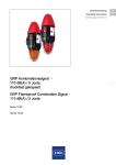
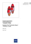
Betriebsanleitung
DE
Operating instructions
EN
Additional languages www.stahl-ex.com
EN
DE EN
DE
EN
EN
DE
EN
EN
DE
EN
EN
DE
EN
EN
DE
EN
EN
GRP Akustisches Signal - 110 dB(A),
druckfest gekapselt
GRP Flameproof Audible Signal 110 dB(A)
Reihe YA6S
Series YA6S
DE
EN
EN
DE
EN
EN
DE
Betriebsanleitung
DE
Additional languages www.stahl-ex.com
DE
DE
DE
DE
DE
DE
DE
DE
DE
DE
DE
DE
DE
DE
DE
DE
DE
DE
GRP Akustisches Signal - 110 dB(A),
druckfest gekapselt
Reihe YA6S
DE
DE
DE
DE
DE
DE
DE
Allgemeine Angaben
DE
Inhaltsverzeichnis
DE
1
1.1
1.2
1.3
1.4
2
2.1
2.2
2.3
3
3.1
3.2
3.3
4
4.1
5
6
7
7.1
7.2
7.3
8
9
9.1
10
10.1
10.2
10.3
11
12
13
DE
DE
DE
DE
DE
DE
DE
DE
DE
DE
DE
DE
DE
DE
DE
DE
DE
DE
DE
DE
DE
DE
DE
Allgemeine Angaben ...........................................................................................2
Hersteller .............................................................................................................2
Angaben zur Betriebsanleitung ...........................................................................3
Weitere Dokumente ............................................................................................3
Konformität zu Normen und Bestimmungen .......................................................3
Erläuterung der Symbole ....................................................................................3
Symbole in der Betriebsanleitung .......................................................................3
Warnhinweise .....................................................................................................4
Symbole am Gerät ..............................................................................................5
Sicherheitshinweise ............................................................................................5
Aufbewahrung der Betriebsanleitung ..................................................................5
Sichere Verwendung ...........................................................................................5
Umbauten und Änderungen ................................................................................5
Funktion und Geräteaufbau ................................................................................5
Funktion ..............................................................................................................6
Technische Daten ...............................................................................................6
Transport und Lagerung .....................................................................................7
Montage und Installation .....................................................................................8
Maßangaben / Befestigungsmaße ......................................................................8
Montage / Demontage, Gebrauchslage ..............................................................8
Installation .........................................................................................................15
Inbetriebnahme .................................................................................................15
Betrieb ...............................................................................................................16
Fehlerbeseitigung .............................................................................................16
Instandhaltung, Wartung, Reparatur .................................................................16
Instandhaltung ..................................................................................................16
Reparatur ..........................................................................................................17
Rücksendung ....................................................................................................17
Reinigung ..........................................................................................................17
Entsorgung ........................................................................................................18
Zubehör und Ersatzteile ...................................................................................18
1
Allgemeine Angaben
1.1
Hersteller
2
R. STAHL Schaltgeräte GmbH
Business Unit Lighting & Signalling
Nordstr. 10
99427 Weimar
Germany
R. STAHL Schaltgeräte GmbH
Tel.:
Fax
Internet:
E-Mail:
Tel.:
Fax
Internet:
E-Mail:
+49 3643 4324
+49 3643 4221-76
www.stahl-ex.com
[email protected]
GRP Akustisches Signal - 110 dB(A),
druckfest gekapselt
Reihe YA6S
Am Bahnhof 30
74638 Waldenburg
Germany
+49 7942 943-0
+49 7942 943-4333
www.stahl-ex.com
[email protected]
Erläuterung der Symbole
1.2
Angaben zur Betriebsanleitung
ID-Nr.
Publikationsnummer:
DE
DE
224617 / YA6S60300010
2015-06-16·BA00·III·de·00
DE
DE
Die Originalbetriebsanleitung ist die englische Ausgabe.
Diese ist rechtsverbindlich in allen juristischen Angelegenheiten.
1.3
1.4
DE
DE
Weitere Dokumente
DE
• Datenblatt
Weitere Sprachen, siehe www.stahl-ex.com.
DE
DE
Konformität zu Normen und Bestimmungen
DE
Siehe Zertifikate und EG-Konformitätserklärung: www.stahl-ex.com.
Das Gerät verfügt über eine IECEx-Zulassung. Siehe IECEx-Homepage:
http://iecex.iec.ch/
DE
DE
DE
2
Erläuterung der Symbole
DE
2.1
Symbole in der Betriebsanleitung
DE
Symbol
DE
DE
Bedeutung
DE
Tipps und Empfehlungen zum Gebrauch des Geräts
DE
DE
DE
Gefahr allgemein
DE
DE
DE
DE
Gefahr durch explosionsfähige Atmosphäre
Gefahr durch spannungsführende Teile
224617 / YA6S60300010
2015-06-16·BA00·III·de·00
GRP Akustisches Signal - 110 dB(A),
druckfest gekapselt
Reihe YA6S
3
Erläuterung der Symbole
DE
= Signal
DE
DE
= Erde
DE
DE
1
= Signal Stufe 1
2
= Signal Stufe 2
3
= Signal Stufe 3
DE
DE
DE
DE
DE
= Signalton
DE
DE
DE
DE
= Telefonanschluss
2.2
DE
DE
DE
DE
DE
Warnhinweise
Warnhinweise unbedingt befolgen, um das konstruktive und durch den Betrieb bedingte
Risiko zu minimieren. Die Warnhinweise sind wie folgt aufgebaut:
• Signalwort: GEFAHR, WARNUNG, VORSICHT, HINWEIS
• Art und Quelle der Gefahr/des Schadens
• Folgen der Gefahr
• Ergreifen von Gegenmaßnahmen zum Vermeiden der Gefahr/des Schadens
GEFAHR
DE
Gefahren für Personen
Nichtbeachtung der Anweisung führt zu schweren oder tödlichen
Verletzungen bei Personen.
DE
DE
WARNUNG
DE
DE
Gefahren für Personen
Nichtbeachtung der Anweisung kann zu schweren oder tödlichen
Verletzungen bei Personen führen.
DE
VORSICHT
Gefahren für Personen
Nichtbeachtung der Anweisung kann zu leichten Verletzungen bei Personen
führen.
HINWEIS
Vermeidung von Sachschaden
Nichtbeachtung der Anweisung kann zu einem Sachschaden am Gerät und/oder seiner
Umgebung führen.
4
GRP Akustisches Signal - 110 dB(A),
druckfest gekapselt
Reihe YA6S
224617 / YA6S60300010
2015-06-16·BA00·III·de·00
Sicherheitshinweise
2.3
DE
Symbole am Gerät
Symbol
DE
Bedeutung
CE-Kennzeichnung gemäß aktuell gültiger Richtlinie.
DE
DE
05594E00
Gerät gemäß Kennzeichnung für explosionsgefährdete Bereiche zertifiziert.
DE
02198E00
Eingang
DE
DE
15649E00
Ausgang
DE
15648E00
DE
3
Sicherheitshinweise
3.1
Aufbewahrung der Betriebsanleitung
3.2
3.3
DE
DE
DE
• Betriebsanleitung sorgfältig lesen und am Einbauort des Geräts aufbewahren.
• Mitgeltende Dokumente und Betriebsanleitungen der anzuschließenden Geräte
beachten.
DE
Sichere Verwendung
DE
DE
DE
• Sicherheitshinweise in dieser Betriebsanleitung lesen und beachten!
• Kennwerte und Bemessungsbetriebsbedingungen der Typ- und Datenschilder
beachten!
• Zusätzliche Hinweisschilder auf dem Gerät beachten!
• Gerät nur bestimmungsgemäß und nur für den zugelassenen Einsatzzweck
verwenden!
• Für Schäden, die durch fehlerhaften oder unzulässigen Einsatz sowie durch
Nichtbeachtung dieser Betriebsanleitung entstehen, besteht keine Haftung.
• Vor Installation und Inbetriebnahme sicherstellen, dass das Gerät unbeschädigt ist!
• Arbeiten am Gerät (Installation, Instandhaltung, Wartung, Störungsbeseitigung) nur
von dazu befugtem und entsprechend geschultem Personal durchführen lassen!
Umbauten und Änderungen
GEFAHR
Explosionsgefahr durch Umbauten und Änderungen am Gerät!
Nichtbeachten führt zu schweren oder tödlichen Verletzungen.
• Gerät nicht umbauen oder verändern. Für Schäden, die durch
Umbauten und Änderungen entstehen, besteht keine Haftung und keine
Gewährleistung.
4
DE
Funktion und Geräteaufbau
GEFAHR
Explosionsgefahr durch zweckentfremdete Verwendung!
Nichtbeachten führt zu schweren oder tödlichen Verletzungen.
• Gerät ausschließlich entsprechend den in dieser Betriebsanleitung
festgelegten Betriebsbedingungen verwenden.
224617 / YA6S60300010
2015-06-16·BA00·III·de·00
GRP Akustisches Signal - 110 dB(A),
druckfest gekapselt
Reihe YA6S
5
DE
DE
DE
DE
DE
DE
DE
DE
Technische Daten
DE
DE
4.1
Funktion
5
Technische Daten
DE
DE
DE
DE
DE
DE
Die Produktreihe YA6S liefert ein akustisches Signal, welches zur Alarmierung, Warnung
oder als Hinweis auf ein Ereignis vorgesehen ist. Das Gerät zeichnet sich durch seine
Korrosionsbeständigkeit aus und ist daher besonders geeignet für den Einsatz in
rauesten Umgebungen sowohl Onshore und Offshore.
Explosionsschutz
DE
Global (IECEx)
DE
Gas und Staub
DE
IECEx BAS 14.0064
IEC 60079-0: 2011 / IEC 60079-1: 2007 / IEC 60079-31: 2013
DE
Ex d IIB T* Ta -** ... +** °C Gb
Ex d IIC T* Ta -** ... +** °C Gb
DE
Ex tb IIIC T*** °C Ta -** ... +** °C Db IP66
DE
Europa (ATEX)
DE
Gas und Staub
DE
Baseefa14ATEX0126
EN 60079-0: 2012 / EN 60079-1: 2007 / EN 60079-31: 2009
(IEC 60079-31: 2013)
DE
DE
E II 2 G Ex d IIB T* Ta -** ... Ta +** °C Gb
E II 2 G Ex d IIC T* Ta -** ... Ta +** °C Gb
DE
E II 2 D Ex tb IIIC T*** °C Ta -** ... +** °C Db IP66
DE
Produktvariantentabelle
DE
DE
DE
DE
DE
Strom und
Spannung
Temperaturklasse
Max. Oberflächentemperatur
Umgebungstemperaturbereich
24 V DC
T6
T75 °C
-60 … +70 °C
48 V DC
T6
T75 °C
-60 … +70 °C
115 V AC
T6
T77 °C
-60 … +60 °C
T5
T87 °C
-60 … +70 °C
T6
T77 °C
-60 … +60 °C
T5
T87 °C
-60 … +70 °C
240 V AC
Bescheinigungen und Zertifikate
Bescheinigungen
IECEx, ATEX
Umgebungsbedingungen
Betriebstemperaturbereich
6
24/48 V DC -60 ... +70 °C
115 V AC
-40 ... +60 °C
230 V AC
-40 ... +60 °C
GRP Akustisches Signal - 110 dB(A),
druckfest gekapselt
Reihe YA6S
224617 / YA6S60300010
2015-06-16·BA00·III·de·00
Transport und Lagerung
DE
Technische Daten
DE
Elektrische Daten
DE
Bemessungsbetriebsspannung
Stromaufnahme
24 oder 48 V DC
115 oder 230 V AC
24 V DC
280 mA
48 V DC
250 mA
115 V AC
76 mA
230 V AC
40 mA
Betriebsparameter
+
Leitungsüberwachung
ja
DE
DE
DE
DE
DE
DE
/-10 %
DE
DE
DE
Akustische Daten
Volumen
max. 110 dB(A)
DE
Lautstärkeregelung
18 dB(A) Abgleich
Tonstufen
3
DE
Tonwahl
über DIL-Schalter
DE
DE
Mechanische Daten
DE
Material
DE
Gehäuse
glasfaserverstärktes Polyester
Horn and trumpet
ABS, flammhemmend
Montageteile
Edelstahl
DE
Bügel
Edelstahl
DE
Schilder
Polyesterfolie, selbstklebend
DE
IP66 / IP67 gem. IEC 60529
DE
Schutzart
DE
Montage / Installation
Anschluss
DE
2
2,5 mm Klemmen
DE
Technische Daten
Elektrische Daten
Einschaltstrom
6
DC 24 V / 48 V
AC 115 V
AC 230 V
Imax
Dauer
Imax
Dauer
Imax
Dauer
14,5 A
220 μs
10 A
300 μs
25 A
310 μs
Transport und Lagerung
• Gerät nur in Originalverpackung transportieren und lagern.
• Gerät trocken (keine Betauung) und erschütterungsfrei lagern.
• Gerät nicht stürzen.
224617 / YA6S60300010
2015-06-16·BA00·III·de·00
GRP Akustisches Signal - 110 dB(A),
druckfest gekapselt
Reihe YA6S
7
Montage und Installation
DE
7
Montage und Installation
DE
7.1
Maßangaben / Befestigungsmaße
105
[4,13]
DE
33 [1,30]
DE
DE
DE
DE
3 x M6
33
[1,30]
DE
Ø9
[Ø0,35]
263,50 [10,37]
155,50
[6,12]
DE
75 [2,95]
Maßzeichnungen (alle Maße in mm [Zoll]) - Änderungen vorbehalten
DE
75
[2,95]
95
[3,74]
178,50 [7,03]
32
[1,26]
189 [7,44]
117
[4,61]
DE
DE
DE
Ø145
[Ø 5,70]
DE
178,50 [7,03]
DE
263,50 [10,37]
DE
Ø145
[Ø5,70]
DE
17150E00
DE
GRP Akustisches SignalReihe YA6S
mit L-Bügel
DE
DE
117 [4,61]
75 [2,95]
DE
DE
GRP Akustisches Signal Reihe YA6S
ohne L-Bügel
105 [4,13]
20 [0,79]
DE
16919E00
DE
ø9 [ø0,35]
DE
17159E00
L-Bügel
7.2
Montage / Demontage, Gebrauchslage
GEFAHR
Explosionsgefahr!
Gefahr von Verletzungen und Sachschäden!
• Bei Verwendung von Aderendhülsen müssen diese unbedingt gasdicht
mit geeignetem Werkzeug angebracht werden.
8
GRP Akustisches Signal - 110 dB(A),
druckfest gekapselt
Reihe YA6S
224617 / YA6S60300010
2015-06-16·BA00·III·de·00
Montage und Installation
DE
GEFAHR
Explosionsgefahr!
Gefahr von Verletzungen und Sachschäden!
• Die Komponenten sorgfältig entfernen oder austauschen.
• Freiliegende Spaltoberflächen nicht beschädigen sowie vor Staub und
Schmutz schützen.
• Die Endflansche ohne Kraftanwendung gerade einbauen, nicht mit
einem Hammer oder sonstigen Werkzeugen bearbeiten und nicht mit
den Befestigungsschrauben nach unten ziehen.
DE
DE
DE
DE
DE
DE
DE
• Das Gerät auf eine plane und dem Gewicht entsprechende Oberfläche montieren.
• Die Kabel mit einer zugelassenen und für die Gasgruppe geeigneten druckfesten
Kabel- und Leitungseinführung einbringen.
• Nicht genutzte Einführungen mit zugelassenen, druckfesten Verschlussstopfen
verschließen.
DE
DE
DE
DE
7.2.1 Einbaubedingungen Netzanschluss
DE
GEFAHR
Explosionsgefahr!
Gefahr von Verletzungen und Sachschäden!
• Nur Kabelverschraubungen mit entsprechender Zertifizierung verwenden. Kabelverschraubungen müssen zünddurchschlagsicher (Ex d) und
für die jeweils verwendete Kabelart geeignet sein.
• Nicht verwendete Bohrungen im Gehäuse mit druckfesten
Verschlussstopfen verschließen.
• Nicht verwendete Kabelverschraubungen mit druckfesten Stopfen
verschließen.
• Kabelverschraubungen, Verschlussstopfen und Stopfen müssen die
Anforderungen der IEC/EN 60079-14 erfüllen.
• Die Installation der Kabelverschraubung muss entsprechend den
Herstelleranweisungen erfolgen.
• Die Temperatur der Leitungseinführung kann 70 °C erreichen.
• Die Gewinde mit einem nichthärtenden Gewindedichtstoff versehen, um
die Schutzart IP 66 sicherzustellen.
GEFAHR
Gefahr durch spannungsführende Teile!
Tod oder schwerste Verletzungen drohen!
• Gerät vor dem Öffnen und vor der Demontage spannungsfrei schalten.
• Gerät gegen unbefugtes Schalten sichern.
224617 / YA6S60300010
2015-06-16·BA00·III·de·00
DE
GRP Akustisches Signal - 110 dB(A),
druckfest gekapselt
Reihe YA6S
9
DE
DE
DE
DE
DE
DE
DE
DE
DE
DE
DE
Montage und Installation
DE
DE
7.2.2 Montage mit Befestigungswinkel
• Bügel an Wand anbringen
DE
• Gerät befestigen
DE
DE
DE
DE
DE
DE
DE
DE
DE
DE
DE
17161E00
17219E00
DE
DE
DE
1
2
3
4
1
DE
DE
Horn
Leiterplatte
Endkappe
Zylinderkopfschrauben M5 x 25
DE
DE
2
DE
DE
3
DE
DE
4
17220E00
•
•
•
•
•
6 x Zylinderkopfschrauben (4) lösen und Endkappe (3) entfernen
Kabel- und Leitungseinführung vorbereiten
Erdungsanschluss sicherstellen
Kabelverschraubung montieren
Leitungen anschließen (siehe elektrischer Anschluss)
7.2.3 Zusammenbau des Gehäuses
• Die Endkappe in Richtung Gerät anheben.
• Die Zylinderkopfschrauben M5 x 25 (siehe unten, Information) ersetzen und mit einen
Drehmoment von 4 Nm anziehen.
10
GRP Akustisches Signal - 110 dB(A),
druckfest gekapselt
Reihe YA6S
224617 / YA6S60300010
2015-06-16·BA00·III·de·00
Montage und Installation
DE
7.2.4 Elektrischer Anschluss
DE
Schlüsselkomponenten
DE
3
1
4
1
2
3
4
DE
Stecker für Hupe
Anschlussleiterplatte
Klemmblöcke
Tonwahlschalter (siehe Tontabelle)
DE
DE
DE
2
DE
DE
DE
17230E00
Schlüsselkomponenten YL6S
DE
DE
Kabelanschluss
DE
• Die Anschlussklemme ist für Kabel mit einem Querschnitt von 2,5 mm2
oder 14 ... 18 AWG geeignet.
DE
DE
DE
Parallelverbindung mehrere Geräte
Bis zu 10 Geräte können parallel an einer Versorgungsleitung angeschlossen werden
(siehe Verdrahtungsplan).
DE
Schaltpläne
DE
Leitungsüberwachung für Geräte mit Gleichspannung
• durch Polaritätsumkehr
• durch Anschluss eines Abschlusswiderstandes zwischen 0 V und +V.
Der Widerstandswert wird vom Anlagenentwickler festgelegt.
Zwei Signalstufen für Geräte mit Gleichspannung
• durch Anschluss über einen dritten Draht.
Drei Signalstufen für Geräte mit Wechselspannung
• durch Anschluss über einen dritten und vierten Draht.
224617 / YA6S60300010
2015-06-16·BA00·III·de·00
GRP Akustisches Signal - 110 dB(A),
druckfest gekapselt
Reihe YA6S
DE
DE
DE
DE
DE
DE
DE
11
Montage und Installation
DE
DE
DE
DE
DE
DE
DE
TELEPHONE
INITIATE
TELEPHONE
INITIATE
DE
NEUTRAL
NEUTR
0V
2ND
STAGE
LIVE (Vac)
24/48 Vdc
3RD
STAGE
STROBE
AC/DC
DE
DE
0V
DE
1
2
3
+V
+V
+V
0V
DE
DE
N
1
2
3
+V
+V
+V
2
1
L
N
L
1
L
2
L
17228E00
Schaltplan Gleichspannungen
DE
DE
1
= Signal Stufe 1
2
= Signal Stufe 2
3
= Signal Stufe 3
DE
DE
17227E00
Schaltplan Wechselspannungen
DE
DE
DE
DE
7.2.5 Erdanschluss
DE
DE
E
DE
DE
17191E00
Erdungsanschluss
Verwendung von metallischen Kabel- und Leitungseinführungen
Eine Erdungsfahne ist für jedes Gerät vorgesehen. Diese sollte wie oben beschrieben mit
dem externen Erdungsbolzen verbunden werden.
Gerätematerial
Das für das Gehäuse verwendete GRP Material besitzt elektrisch leitende
Eigenschaften. Das Material ist antistatisch und verhindert die Bildung elektrischer
Ladungen auf der Oberfläche.
Spezifischer Oberflächenwiderstand < 108 Ω gemäß IEC 60093
12
GRP Akustisches Signal - 110 dB(A),
druckfest gekapselt
Reihe YA6S
224617 / YA6S60300010
2015-06-16·BA00·III·de·00
Montage und Installation
DE
7.2.6 Einstellbare Tonfolgen
DE
DE
• Signaltonauswahl und deren Schalterpositionen: siehe Tabelle unten.
• Kontrollieren der korrekten Schalterpositionen der ausgewählten Signaltöne
DE
DE
Tontabelle
DE
Tonwahlschalter
12345
(EIN = 1)
Wiederholfrequenz
(sec)
Ton 01 Zwei alternierende Töne 800-1000
00000
0,5
Feueralarme Bahnübergang
Ton 02 Zwei alternierende Töne 2500-3100
10000
0,5
Sicherheitsalarme
DE
Ton 03 Zwei schnell
alternierende Töne
800-1000
01000
0,25
Erhöhte Dringlichkeit Bahnübergang
DE
Ton 04 Zwei schnell
alternierende Töne
2500-3100
11000
0,25
Sicherheitsabschreckung
Ton 05 Zwei alternierende Töne 440-554
00100
0,4/0,1
AFNOR, Frankreich
Ton 06 Zwei alternierende Töne 430-470
10100
1,0
DE
Ton 07 Zwei sehr schnell
alternierende Töne
800-1000
01100
0,13
DE
Ton 08 Zwei sehr schnell alternierende Töne
2500-3200
11100
0,07
Ton 09 Zwei alternierende Töne 440-554
00010
2,0
Ton 10 Dauerton
700
10010
Ton 11 Dauerton
1000
01010
DE
Ton 12 Dauerton
1000
11010
DE
Ton 13 Dauerton
2300
00110
DE
Ton 14 Dauerton
440
10110
Ton 15 Unterbrochener Ton
1000
01110
2,0
Ton 16 Unterbrochener Ton
420
11110
1,25
Ton 17 Unterbrochener Ton
1000
00001
0,5
Ton 18 Unterbrochener Ton
2500
10001
0,25
Ton 19 Unterbrochener Ton
2500
01001
0,5
Ton 20 Unterbrochener Ton
700
11001
6/12
Ton 21 Unterbrochener Ton
1000
00101
1,0
Ton 22 Unterbrochener Ton
700
10101
4,0
Luftangriffalarm, Schweden
Ton 23 Unterbrochener Ton
700
01101
0,25
Lokale Warnung, Schweden
Ton 24 Unterbrochener Ton
720
11101
0,7/0,3
Industriealarm, Deutschland
Ton 25 Unterbrochen, schnell,
ansteigende Lautstärke
1400
00011
0,25
Ton 26 Schnelle Sirene
250-1200
10011
0,085
Ton
Nr.
Ausführung
224617 / YA6S60300010
2015-06-16·BA00·III·de·00
Häufigkeit
DE
Sonderanwendung
DE
DE
DE
DE
DE
DE
DE
DE
Rettungsgasse bilden,
Schweden (SS 031711)
DE
Entwarnung, Schweden (SS
031711)
AS2220, Australien
Wichtige Meldung, Schweden
GRP Akustisches Signal - 110 dB(A),
druckfest gekapselt
Reihe YA6S
13
DE
DE
Montage und Installation
DE
Tontabelle
DE
DE
DE
Ton 27 Konstant ansteigend,
abfallend
1000
01011
10/40/10
Industriealarm, Deutschland
Ton 28 ISO 8201 Evakuierung
800-1000
11011
Als Standard
Internationaler
Evakuierungsalarm
Ton 29 Schneller Heulton
500-1000
00111
0,15
Ton 30 Langsamer Heulton
500-1200
10111
4,5
Evakuierung, Niederlande
Ton 31 Rückwärts-Sweep
1200-500
01111
1,0
Feueralarm, Deutschland
(DIN 33404)
Ton 32 Sirene
500-1200
11111
3,0
DE
DE
DE
DE
DE
DE
Die Akustiksignale nach PFEER gemäß Empfehlung von UKOOA lauten:
DE
DE
DE
DE
Generalalarm
Akustisches Signal 15
Unterbrochener Ton 1000 Hz
PAPA
Akustisches Signal 31
Rückwärtssweep 1200-500 Hz
Giftgas
Akustisches Signal 11
Dauerton 1000 Hz
Details Tonwahlschalter
DE
DE
DE
DE
DE
3
2
1
DE
DE
TELEPHONE
INITIATE
NEUTRAL
NEUTR
0V
DE
LIVE (Vac)
24/48 Vdc
2ND
STAGE
3RD
STAGE
STROBE
AC/DC
17192E00
DE
DE
DE
14
GRP Akustisches Signal - 110 dB(A),
druckfest gekapselt
Reihe YA6S
224617 / YA6S60300010
2015-06-16·BA00·III·de·00
Inbetriebnahme
7.3
DE
Installation
DE
WARNUNG
DE
Gefahr eines Stromschlags durch spannungsführende Teile!
Nichtbeachten kann zu schweren oder tödlichen Verletzungen führen.
• Alle Anschlüsse und Verdrahtungen spannungsfrei schalten.
• Anschlüsse gegen unbefugtes Schalten sichern.
DE
DE
DE
GEFAHR
DE
Explosionsgefahr!
Gefahr von Verletzungen und Sachschäden!
• Das Gerät nur in unbeschädigtem Zustand betreiben.
• Bei beschädigtem Gewinde ist das Gerät sofort auszutauschen.
• Das Gerät und die Bauelemente äußerst sorgfältig handhaben.
• Freiliegende Spaltoberflächen vor Staub, Schmutz und
Beschädigungen schützen.
• Die Endflansche unter Vermeidung jeglicher Kraftanwendung gerade
einbauen.
• Den Flansch nicht mit einem Hammer oder anderen Metallwerkzeugen
bearbeiten.
• Den Flansch nicht mit den Befestigungsschrauben nach unten ziehen.
• Das Gerät nur in sauberer und trockener Betriebsumgebung
eingebauen.
DE
DE
DE
DE
DE
DE
DE
DE
DE
DE
DE
DE
8
Inbetriebnahme
DE
DE
GEFAHR
DE
Explosionsgefahr durch fehlerhafte Installation!
Nichtbeachten führt zu schweren oder tödlichen Verletzungen.
• Gerät vor der Inbetriebnahme auf korrekte Installation und Funktion
prüfen.
• Nationale Bestimmungen einhalten.
DE
DE
DE
Vor Inbetriebnahme, stellen Sie sicher, dass
• das Gerät vorschriftsmäßig installiert wurde.
• die Netzspannung mit der Bemessungsbetriebsspannung des Gerätes übereinstimmt.
• der für die Kabel- und Leitungseinführung zulässige Kabeldurchmesser verwendet
wurde.
• die Leitungseinführungen und Verschlussstopfen fest angezogen sind.
• die Kabel ordnungsgemäß eingeführt sind.
• der Anschluss ordnungsgemäß ausgeführt wurde.
• alle Schrauben und Muttern vorschriftsmäßig angezogen sind.
• der Anschlussraum sauber ist.
• das Gerät nicht beschädigt ist.
• sich keine Fremdkörper im Gerät befinden.
• das Gerät vorschriftsmäßig verschlossen ist.
224617 / YA6S60300010
2015-06-16·BA00·III·de·00
GRP Akustisches Signal - 110 dB(A),
druckfest gekapselt
Reihe YA6S
15
Betrieb
DE
DE
9
Betrieb
9.1
Fehlerbeseitigung
10
Instandhaltung, Wartung, Reparatur
DE
DE
DE
DE
DE
DE
DE
DE
DE
Das Gerät warnt und alarmiert mittels
• akustischem Signal.
Tritt ein Fehler auf, lesen Sie bitte die vorherigen Abschnitte dieses Dokuments.
Wenn sich der Fehler mit den genannten Vorgehensweisen nicht beheben lässt:
• An R. STAHL Schaltgeräte GmbH wenden.
Zur schnellen Bearbeitung folgende Angaben bereithalten:
• Typ und Seriennummer
• Kaufdaten
• Fehlerbeschreibung
• Einsatzzweck (insbesondere Eingangs-/Ausgangsbeschaltung)
DE
DE
DE
WARNUNG
DE
Stromschlaggefahr bzw. Fehlfunktion des Geräts durch unbefugte Arbeiten!
Nichtbeachten kann zu schweren Verletzungen und Sachschäden führen.
• Arbeiten am Gerät ausschließlich von dazu autorisierter und
entsprechend geschulter Elektro-Fachkraft ausführen lassen.
DE
DE
DE
DE
10.1 Instandhaltung
DE
Die geltenden nationalen Bestimmungen im Einsatzland beachten.
DE
DE
DE
DE
• Art und Umfang der Prüfungen unter Beachtung der entsprechenden nationalen
Vorschriften festlegen.
• Prüfungsintervalle an Betriebsbedingungen anpassen.
DE
16
GRP Akustisches Signal - 110 dB(A),
druckfest gekapselt
Reihe YA6S
224617 / YA6S60300010
2015-06-16·BA00·III·de·00
Reinigung
DE
Folgende Prüfungen und Maßnahmen müssen mindestens bei der regelmäßigen
Wartung durchgeführt werden.
DE
DE
Prüfen
Maßnahmen
der zulässigen Umgebungstemperatur
Bei Über- oder Unterschreiten der
zulässigen Umgebungstemperatur ist das
Gerät außer Betrieb zu nehmen.
der Gehäusekomponenten auf
Rissbildung oder Beschädigungen
der bestimmungsgemäßen Verwendung
des festen Sitzes der untergeklemmten
Leitungen
Austauschbare Gehäusekomponenten
tauschen. Bei nicht austauschbaren
Gehäusekomponenten ist das Gerät außer
Betrieb zu nehmen.
Bei nicht bestimmungsgemäßer Verwendung ist das Gerät außer Betrieb zu nehmen.
DE
DE
DE
DE
DE
DE
DE
DE
DE
Lockere Leitungen fest unterklemmen.
DE
der Kabel auf Alterung und Beschädigung Beschädigte oder gealterte Kabel
ersetzen.
DE
auf Alterung und Beschädigung der
Dichtung
DE
DE
Beschädigte, gealterte oder poröse
Dichtungen ersetzen.
Gehäusekomponenten mit geschäumter
Dichtung komplett tauschen.
10.2 Reparatur
DE
DE
DE
DE
DE
GEFAHR
DE
Explosionsgefahr durch unsachgemäße Reparatur!
Nichtbeachten führt zu schweren oder tödlichen Verletzungen.
• Reparaturen an den Geräten ausschließlich durch
R. STAHL Schaltgeräte GmbH ausführen lassen.
DE
DE
10.3 Rücksendung
Für die Rücksendung im Reparatur-/Servicefall das Formular "Serviceschein" verwenden. Auf der Internetseite "www.stahl-ex.com" im Menü "Downloads > Kundenservice":
• Serviceschein herunterladen und ausfüllen.
• Gerät zusammen mit dem Serviceschein wieder in der Originalverpackung an die
R. STAHL Schaltgeräte GmbH senden.
11
DE
Reinigung
• Gerät nur mit einem Tuch, Besen, Staubsauger o.ä. reinigen.
• Bei feuchter Reinigung: Wasser oder milde, nicht scheuernde, nicht kratzende
Reinigungsmittel verwenden.
• Keine aggressiven Reinigungsmittel oder Lösungsmittel verwenden.
224617 / YA6S60300010
2015-06-16·BA00·III·de·00
GRP Akustisches Signal - 110 dB(A),
druckfest gekapselt
Reihe YA6S
17
Entsorgung
DE
DE
12
Entsorgung
13
Zubehör und Ersatzteile
DE
DE
DE
DE
DE
DE
• Nationale und lokal gültige Vorschriften und gesetzliche Bestimmungen zur
Entsorgung beachten.
• Materialien getrennt dem Recycling zuführen.
• Umweltgerechte Entsorgung aller Bauteile gemäß den gesetzlichen Bestimmungen
sicherstellen.
DE
HINWEIS
DE
Fehlfunktion oder Geräteschaden durch den Einsatz nicht originaler Bauteile.
Nichtbeachten kann Sachschaden verursachen!
• Nur Original-Zubehör und Original-Ersatzteile der R. STAHL Schaltgeräte GmbH
verwenden.
DE
DE
DE
Zubehör und Ersatzteile, siehe Datenblatt auf Homepage www.stahl-ex.com.
DE
DE
DE
DE
DE
DE
DE
DE
DE
DE
DE
DE
18
GRP Akustisches Signal - 110 dB(A),
druckfest gekapselt
Reihe YA6S
224617 / YA6S60300010
2015-06-16·BA00·III·de·00
Operating instructions
EN
Additional languages www.stahl-ex.com
EN
EN
EN
EN
EN
EN
EN
EN
EN
EN
EN
EN
EN
EN
EN
EN
EN
EN
GRP Flameproof Audible Signal 110 dB(A)
Series YA6S
EN
EN
EN
EN
EN
EN
EN
General Information
EN
Contents
EN
1
1.1
1.2
1.3
1.4
2
2.1
2.2
2.3
3
3.1
3.2
3.3
4
4.1
5
6
7
7.1
7.2
7.3
8
9
9.1
10
10.1
10.2
10.3
11
12
13
EN
EN
EN
EN
EN
EN
EN
EN
EN
EN
EN
EN
EN
EN
EN
EN
EN
EN
EN
EN
EN
EN
EN
General Information ............................................................................................2
Manufacturer .......................................................................................................2
Information regarding the operating instructions .................................................3
Further documents ..............................................................................................3
Conformity with standards and regulations .........................................................3
Explanation of the symbols .................................................................................3
Symbols in these operating instructions .............................................................3
Warning notes .....................................................................................................4
Symbols on the device ........................................................................................5
Safety notes ........................................................................................................5
Operating instructions storage ............................................................................5
Safe use ..............................................................................................................5
Modifications and alterations ..............................................................................5
Function and device design ................................................................................5
Function ..............................................................................................................6
Technical data .....................................................................................................6
Transport and storage .........................................................................................7
Mounting and installation ....................................................................................8
Dimensions / fastening dimensions ....................................................................8
Mounting / dismounting, operating position ........................................................8
Installation .........................................................................................................14
Commissioning .................................................................................................15
Operation ..........................................................................................................15
Troubleshooting ................................................................................................15
Maintenance and repair ....................................................................................16
Maintenance .....................................................................................................16
Repair ...............................................................................................................17
Returning the device .........................................................................................17
Cleaning ............................................................................................................17
Disposal ............................................................................................................17
Accessories and Spare parts ...........................................................................17
1
General Information
1.1
Manufacturer
2
R. STAHL Schaltgeräte GmbH
Business Unit Lighting & Signalling
Nordstr. 10
99427 Weimar
Germany
R. STAHL Schaltgeräte GmbH
Phone:
Fax:
Internet:
E-mail:
Phone:
Fax:
Internet:
E-mail:
+49 3643 4324
+49 3643 4221-76
www.stahl-ex.com
[email protected]
GRP Flameproof Audible Signal - 110 dB(A)
Series YA6S
Am Bahnhof 30
74638 Waldenburg
Germany
+49 7942 943-0
+49 7942 943-4333
www.stahl-ex.com
[email protected]
Explanation of the symbols
1.2
EN
Information regarding the operating instructions
ID-No.:
Publication Code:
EN
224617 / YA6S60300010
2015-06-16·BA00·III·en·00
EN
EN
The original instructions are the English edition.
They are legally binding in all legal affairs.
1.3
1.4
EN
EN
Further documents
EN
• Data sheet
For further languages, see www.stahl-ex.com.
EN
EN
Conformity with standards and regulations
EN
See certificates and EC Declaration of Conformity: www.stahl-ex.com.
The device has IECEx approval. See IECEx homepage: http://iecex.iec.ch/
2
Explanation of the symbols
2.1
Symbols in these operating instructions
Symbol
EN
EN
EN
EN
EN
EN
Meaning
EN
EN
Tips and recommendations on the use of the device
EN
EN
EN
General danger
EN
EN
EN
Danger due to explosive atmosphere
EN
Danger due to energised parts
224617 / YA6S60300010
2015-06-16·BA00·III·en·00
GRP Flameproof Audible Signal - 110 dB(A)
Series YA6S
3
Explanation of the symbols
EN
= Sounder
EN
EN
= Earth
EN
EN
1
= Sounder Stage 1
2
= Sounder Stage 2
3
= Sounder Stage 3
EN
EN
EN
EN
EN
= Sounder Tone
EN
EN
EN
EN
= Telephone initiate
2.2
EN
EN
EN
EN
EN
Warning notes
Warning notes must be observed under all circumstances, in order to minimize the risk
due to construction and operation. The warning notes have the following structure:
• Signalling word: DANGER, WARNING, CAUTION, NOTICE
• Type and source of danger/damage
• Consequences of danger
• Taking countermeasures to avoid the danger/damage
DANGER
EN
Danger to persons
Non-compliance with the instruction results in severe or fatal injuries to
persons.
EN
EN
WARNING
EN
EN
Danger to persons
Non-compliance with the instruction can result in severe or fatal injuries to
persons.
EN
CAUTION
Danger to persons
Non-compliance with the instruction can result in light injuries to persons.
NOTICE
Avoiding material damage
Non-compliance with the instruction can result in material damage to the device
and / or its environment.
4
GRP Flameproof Audible Signal - 110 dB(A)
Series YA6S
224617 / YA6S60300010
2015-06-16·BA00·III·en·00
Safety notes
2.3
EN
Symbols on the device
Symbol
EN
Meaning
CE marking according to the current applicable directive.
EN
EN
05594E00
EN
According to marking, device certified for hazardous areas.
EN
02198E00
Input
EN
EN
15649E00
Output
EN
15648E00
EN
3
Safety notes
3.1
Operating instructions storage
3.2
3.3
EN
EN
EN
• Read the operating instructions carefully and store them at the mounting location of
the device.
• Observe applicable documents and operating instructions of the devices to be
connected.
Safe use
• Read and observe the safety notes in these operating instructions!
• Observe characteristic values and rated operating conditions on the rating and data
plates!
• Observe additional information plates on the device!
• Use the device in accordance with its intended and approved purpose only!
• We cannot be held liable for damage caused by incorrect or unauthorized use or by
non-compliance with these operating instructions.
• Before installation and commissioning, make sure that the device is not damaged!
• Work on the device (installation, maintenance, overhaul, repair) may only be carried
out by appropriately authorized and trained personnel.
Modifications and alterations
DANGER
Explosion hazard due to modifications and alterations to the device!
Non-compliance results in severe or fatal injuries.
• Do not modify or alter the device. No liability or warranty for damage
resulting from modifications and alterations.
4
Function and device design
DANGER
Explosion hazard due to improper use!
Non-compliance results in severe or fatal injuries.
• Use the device only according to the operating conditions described in
these operating instructions.
224617 / YA6S60300010
2015-06-16·BA00·III·en·00
GRP Flameproof Audible Signal - 110 dB(A)
Series YA6S
5
EN
EN
EN
EN
EN
EN
EN
EN
EN
EN
EN
EN
Technical data
EN
EN
4.1
Function
5
Technical data
EN
EN
EN
EN
EN
EN
Product series YA6S is designed to provide an audible signal which can be used to alert,
warn or draw attention to an event. Corrosion resistance is a key feature of the device
which is ideally suited for applications in the harshest of environments both onshore and
offshore.
Explosion Protection
EN
Global (IECEx)
EN
Gas and dust
EN
IECEx BAS 14.0064
IEC 60079-0: 2011 / IEC 60079-1: 2007 / IEC 60079-31: 2013
EN
Ex d IIB T* Ta -** ... +** °C Gb
Ex d IIC T* Ta -** ... +** °C Gb
EN
Ex tb IIIC T*** °C Ta -** ... +** °C Db IP66
EN
Europe (ATEX)
EN
Gas and dust
EN
Baseefa14ATEX0126
EN 60079-0: 2012 / EN 60079-1: 2007 / EN 60079-31: 2009 (IEC 60079-31:
2013)
EN
EN
E II 2 G Ex d IIB T* Ta -** ... Ta +** °C Gb
E II 2 G Ex d IIC T* Ta -** ... Ta +** °C Gb
EN
E II 2 D Ex tb IIIC T*** °C Ta -** ... +** °C Db IP66
EN
Product variant table
EN
EN
EN
EN
EN
Power and
voltage
Temperature
class
Max. surface
temperature
Ambient
temperature range
24 V DC
T6
T75 °C
-60 … +70 °C
48 V DC
T6
T75 °C
-60 … +70 °C
115 V AC
T6
T77 °C
-60 … +60 °C
T5
T87 °C
-60 … +70 °C
T6
T77 °C
-60 … +60 °C
T5
T87 °C
-60 … +70 °C
240 V AC
Certifications and certificates
Certificates
IECEx, ATEX
Ambient conditions
Operating temperature range
6
24/48 V DC
-60 ... +70 °C
115 V AC
-40 ... +60 °C
230 V AC
-40 ... +60 °C
GRP Flameproof Audible Signal - 110 dB(A)
Series YA6S
224617 / YA6S60300010
2015-06-16·BA00·III·en·00
Transport and storage
EN
Technical Data
EN
Electrical data
EN
Rated operational
voltage
Current consumption
24 or 48 V DC
115 or 230 V AC
24 V DC
280 mA
48 V DC
250 mA
115 V AC
76 mA
230 V AC
40 mA
Operational
parameters
+
Line monitoring
yes
EN
EN
EN
EN
EN
EN
EN
/-10 %
EN
EN
Acoustic data
EN
Volume
max. 110 dB(A)
Volume control
18 dB(A) adjustment
Sound stages
3
EN
Sound selection
via DIL switch
EN
EN
EN
Mechanical data
Material
EN
Enclosure
glass reinforced polyester
EN
Horn and trumpet
flame retardant ABS
Assembly parts
stainless steel
EN
Bracket
stainless steel
Labels
polyester foil, adhesive
Degree of protection
EN
EN
EN
IP66 / IP67 acc. to IEC 60529
EN
Mounting / Installation
Connection
EN
2.5 mm2 terminals
Technical Data
Electrical data
Inrush current
6
DC 24 V / 48 V
AC 115 V
AC 230 V
Imax
duration
Imax
duration
Imax
duration
14.5 A
220 μs
10 A
300 μs
25 A
310 μs
Transport and storage
• Transport and store the device only in the original packaging.
• Store the device in a dry place (no condensation) and vibration-free.
• Do not drop the device.
224617 / YA6S60300010
2015-06-16·BA00·III·en·00
GRP Flameproof Audible Signal - 110 dB(A)
Series YA6S
7
Mounting and installation
EN
7
Mounting and installation
EN
7.1
Dimensions / fastening dimensions
105
[4,13]
EN
33 [1,30]
EN
EN
EN
EN
3 x M6
33
[1,30]
EN
Ø9
[Ø0,35]
263,50 [10,37]
155,50
[6,12]
EN
75 [2,95]
Dimensional Drawings (All Dimensions in mm [inches]) - Subject to Alterations
EN
75
[2,95]
95
[3,74]
178,50 [7,03]
32
[1,26]
189 [7,44]
117
[4,61]
EN
EN
EN
Ø145
[Ø 5,70]
EN
178,50 [7,03]
EN
263,50 [10,37]
EN
Ø145
[Ø5,70]
EN
17150E00
EN
GRP Audible Signal Series YA6S
with L-Bracket
EN
EN
20 [0,79]
117 [4,61]
75 [2,95]
EN
EN
EN
GRP Audible Signal Series YA6S
without L-Bracket
105 [4,13]
EN
16919E00
ø9 [ø0,35]
EN
17159E00
L-Bracket
7.2
Mounting / dismounting, operating position
DANGER
Risk of explosion!
Risk of injuries and material damage!
• Terminal sleeves are fitted, they must be gas-tight and applied with a
suitable tool.
8
GRP Flameproof Audible Signal - 110 dB(A)
Series YA6S
224617 / YA6S60300010
2015-06-16·BA00·III·en·00
Mounting and installation
EN
DANGER
Explosion hazard!
Risk of injuries and material damage!
• Carefully remove or replace the components.
• Exposed joint surfaces must not be damaged and must be protected
from dust and dirt.
• Install the end flanges squarely without applying any force. Do not use
a hammer or other tools when working on the flanges and do not use the
fixing screws to pull down the flanges.
• Mount the device on a flat surface suitable for its weight.
• Insert the cables using certified and flameproof cable glands which are suitable for the
gas group.
• Close unused entries using certified and flameproof stopping plugs.
7.2.1 Installation Conditions for Electrical Connection
EN
EN
EN
EN
EN
EN
EN
EN
EN
EN
Explosion hazard!
Risk of injuries and material damage!
• Only use cable glands with corresponding certificate. The cable glands
must be flameproof (Ex d) and suitable for the type of cable used.
• Close unused open holes in the enclosure with flameproof stopping
plugs.
• Close unused cable glands using flameproof plugs.
• Cable glands, stopping plugs and plugs must meet the requirements of
IEC/EN 60079-14.
• Installation of the cable gland must be performed in accordance with the
manufacturer's instructions.
• Cable entry temperature may reach 70 °C.
• To ensure degree of protection IP 66, a non-hardening sealant must be
applied to the threads.
DANGER
Danger due to energised parts!
Risk of death or severe injuries!
• Before opening and dismounting the device, disconnect it from the
power supply.
• Secure the device against unauthorized switching.
GRP Flameproof Audible Signal - 110 dB(A)
Series YA6S
EN
EN
DANGER
224617 / YA6S60300010
2015-06-16·BA00·III·en·00
EN
9
EN
EN
EN
EN
EN
EN
EN
EN
EN
EN
EN
Mounting and installation
EN
EN
7.2.2 Installation with mounting bracket
• Fix bracket to wall
EN
• Attach device
EN
EN
EN
EN
EN
EN
EN
EN
EN
EN
EN
17161E00
17219E00
EN
EN
EN
1
2
3
4
1
EN
EN
Horn
PCB
End cap
Cheese-head screws M5 x 25
EN
EN
2
EN
EN
3
EN
EN
4
17220E00
•
•
•
•
•
Loosen 6 x cheese head screws (4) and remove end cap (3)
Prepare cable gland
Ensure earth connection
Install cable gland
Connect cables (see electrical connection)
7.2.3 Reassembly of Enclosure
• Lift end cap towards device.
• Replace cheese-head screws M5 x 25 (see information below) and tighten the screws
with a tightening torque of 4 Nm.
10
GRP Flameproof Audible Signal - 110 dB(A)
Series YA6S
224617 / YA6S60300010
2015-06-16·BA00·III·en·00
Mounting and installation
EN
7.2.4 Electrical Connection
EN
Key Components
EN
3
1
4
2
1
2
3
4
EN
plug for sounder
PCB Termination board
Terminal blocks
Sound selection switch
(see tone table)
EN
EN
EN
EN
EN
EN
17230E00
Key components YL6S
EN
EN
Cable Connection
EN
EN
• The terminals accept wires of 2.5 mm2 or 14 ... 18 AWG.
EN
EN
Interconnection of devices parallel
Up to 10 devices with common supplies may be connected as a single system loop.
See wiring diagrams for further information.
EN
Circuit diagrams
EN
EN
EN
Line monitoring for devices with DC
• by reverse polarity
• by connecting an EOL resistor between 0 V and +V. The resistance
value is defined by the system developer.
EN
EN
EN
EN
Two signal levels for devices with DC
• by connecting the third wire.
Three signal levels for devices with AC
• by connecting the third and fourth wire.
224617 / YA6S60300010
2015-06-16·BA00·III·en·00
GRP Flameproof Audible Signal - 110 dB(A)
Series YA6S
EN
11
Mounting and installation
EN
EN
EN
EN
EN
EN
EN
TELEPHONE
INITIATE
TELEPHONE
INITIATE
EN
NEUTRAL
NEUTR
0V
2ND
STAGE
LIVE (Vac)
24/48 Vdc
3RD
STAGE
STROBE
AC/DC
EN
EN
0V
EN
1
2
3
+V
+V
+V
0V
EN
EN
N
1
2
3
+V
+V
+V
2
1
L
N
L
1
L
2
L
17228E00
Circuit diagram DC voltages
EN
EN
1
= Sounder Stage 1
2
= Sounder Stage 2
3
= Sounder Stage 3
EN
EN
17227E00
Circuit diagram AC voltages
EN
EN
EN
EN
7.2.5 Earth Connection
EN
EN
E
EN
EN
17191E00
Earth connection
Use of metallic cable glands
A slip on earth tag is provided with each device. This should be connected to the external
earth stud detailed above.
Device material
The GRP material used for the device enclosure has electrically conductive properties.
The material is antistatic and prevents build-up of electrical charges on its surface.
Surface resistivity < 108 Ω accordance to IEC 60093
12
GRP Flameproof Audible Signal - 110 dB(A)
Series YA6S
224617 / YA6S60300010
2015-06-16·BA00·III·en·00
Mounting and installation
EN
7.2.6 Sound Tone Selection
EN
• For signal tone selection and its switch positions refer to the table below.
• Check if the correct switch positions of the selected signal tones have been selected.
EN
EN
EN
Tone table
Tone no. Version
Frequency
Tone 01
Alternate two-tone
800-1000
00000
0.5
Fire alarms - Level
crossing
Tone 02
Alternate two-tone
2500-3100
10000
0.5
Security alarms
Tone 03
Alternate fast two-tone
800-1000
01000
0.25
Increased
urgency - Level
crossing
Tone 04
Alternate fast two-tone
2500-3100
11000
0.25
Security deterrent
Tone 05
Alternate two-tone
440-554
00100
0.4/0.1
AFNOR, France
Tone 06
Alternate two-tone
430-470
10100
1.0
Tone 07
Alternate very fast
two-tone
800-1000
01100
0.13
Tone 08
Alternate very fast
two-tone
2500-3200
11100
0.07
Tone 09
Alternate two-tone
440-554
00010
2.0
Tone 10
Continuous tone
700
10010
Tone 11
Continuous tone
1000
01010
Tone 12
Continuous tone
1000
11010
Tone 13
Continuous tone
2300
00110
EN
Tone 14
Continuous tone
440
10110
EN
Tone 15
Interrupted tone
1000
01110
2.0
Tone 16
Interrupted tone
420
11110
1.25
Tone 17
Interrupted tone
1000
00001
0.5
Tone 18
Interrupted tone
2500
10001
0.25
Tone 19
Interrupted tone
2500
01001
0.5
Tone 20
Interrupted tone
700
11001
6/12
Tone 21
Interrupted tone
1000
00101
1.0
Tone 22
Interrupted tone
700
10101
4.0
Air-raid alarm,
Sweden
Tone 23
Interrupted tone
700
01101
0.25
Local warning,
Sweden
Tone 24
Interrupted tone
720
11101
0.7/0.3
Industrial alarm,
Germany
Tone 25
Interrupted, fast, rising
volume
1400
00011
0.25
224617 / YA6S60300010
2015-06-16·BA00·III·en·00
Repetition r
ate (sec)
Special application
EN
Sound selection
switch 12345
(ON = 1)
EN
EN
EN
EN
EN
EN
EN
EN
EN
EN
EN
EN
Turn out, Sweden
(SS 031711)
All clear, Sweden
(SS 031711)
EN
EN
EN
EN
EN
AS2220, Australia
Important message,
Sweden
GRP Flameproof Audible Signal - 110 dB(A)
Series YA6S
13
Mounting and installation
EN
Tone table
EN
EN
EN
EN
EN
EN
EN
EN
EN
EN
Tone 26
Fast siren
Tone 27
250-1200
10011
0.085
Rising constantly, falling 1000
01011
10/40/10
Tone 28
ISO 8201 Evacuation
800-1000
11011
As standard International
evacuation alarm
Tone 29
Fast whoop
500-1000
00111
0.15
Tone 30
Slow whoop
500-1200
10111
4.5
Evacuation,
The Netherlands
Tone 31
Reverse sweep
1200-500
01111
1.0
Fire alarm, Germany
(DIN 33404)
Tone 32
Siren
500-1200
11111
3.0
Industrial alarm,
Germany
The PFEER sound signals recommended by UKOOA are:
EN
EN
General alarm
Sound signal 15
Interrupted tone 1000 Hz
EN
PAPA
Sound signal 31
Reverse sweep 1200-500 Hz
EN
Toxic gas
Sound signal 11
Continuous tone 1000 Hz
EN
Details sound selection switch
EN
EN
EN
EN
EN
3
2
1
EN
TELEPHONE
INITIATE
EN
NEUTRAL
NEUTR
0V
2ND
STAGE
LIVE (Vac)
24/48 Vdc
EN
EN
3RD
STAGE
STROBE
AC/DC
17192E00
7.3
Installation
WARNING
Danger of electric shock due to energised parts!
Non-compliance can result in severe or fatal injuries.
• All connections and wiring must be disconnected from the power supply.
• Secure the connections against unauthorized switching.
14
GRP Flameproof Audible Signal - 110 dB(A)
Series YA6S
224617 / YA6S60300010
2015-06-16·BA00·III·en·00
Commissioning
EN
DANGER
Explosion hazard!
Risk of injuries and material damage!
• Operate the device only if it is not damaged.
• If the thread is damaged, the device must be replaced immediately.
• Handle the device and the components very carefully.
• Exposed joint surfaces must be protected from dust, dirt and damage.
• Mount the end flanges squarely and do not apply any force.
• Do not use a hammer or any other metal instruments to work on the
flange.
• Do not use the fixing screws to pull down the flange.
• Install the device only in a clean and dry operating environment.
EN
EN
EN
EN
EN
EN
EN
EN
EN
EN
8
EN
Commissioning
EN
DANGER
EN
Explosion hazard due to incorrect installation!
Non-compliance results in severe or fatal injuries.
• Check the device for proper installation and function before
commissioning.
• Comply with the national regulations.
EN
EN
EN
EN
EN
Before commissioning, ensure that
• the device has been installed according to regulations.
• the power supply voltage and the rated operational voltage are identical.
• the required cable diameter for cable glands has been used.
• the cable entries and stopping plugs have been securely tightened.
• the cables are correctly connected.
• the connection has been performed correctly.
• all screws and nuts are tightened according to regulations.
• the connection chamber is clean.
• the device is not damaged.
• no foreign bodies are inside the device.
• the device is sealed according to regulations.
9
Operation
9.1
Troubleshooting
EN
EN
EN
EN
EN
EN
The device is used to warn and alert by means
• of a sound signal.
If an error occurs please re-visit the earlier sections of this document.
If the error cannot be eliminated using the mentioned procedures:
• Contact R. STAHL Schaltgeräte GmbH.
For fast processing, have the following information ready:
• Type and serial number
• Purchase information
224617 / YA6S60300010
2015-06-16·BA00·III·en·00
GRP Flameproof Audible Signal - 110 dB(A)
Series YA6S
15
Maintenance and repair
EN
• Error description
• Intended use (in particular input / output wiring)
EN
EN
EN
EN
10
Maintenance and repair
WARNING
EN
Risk of electric shock or malfunctioning of the device due to unauthorized
work!
Non-compliance can result in severe injuries and material damage.
• Work performed on the device must only be carried out by appropriately
authorized and qualified electricians.
EN
EN
EN
EN
EN
10.1 Maintenance
EN
Observe the relevant national regulations in the country of use.
EN
EN
EN
EN
• Determine the type and extent of inspections in compliance with the relevant national
regulations.
• Adapt inspection intervals to the operating conditions.
EN
EN
EN
The following tests and measures must be carried out during regular maintenance.
EN
EN
EN
Check
Measures
the permissible ambient temperature
If exceeding the permissible ambient
temperature or falling below the device
must be taken out of operation.
EN
the enclosure components for formation of Replace the exchangeable enclosure
cracks and damage.
components. If the enclosure components
are non-exchangeable, the device must be
taken out of operation.
EN
EN
16
its intended use
If the device is not used according to its
intended use, it must be taken out o
f operation.
if the conductors are clamped properly
clamp loose conductors tightly.
the cables for ageing and damage
replace damaged or aged cables.
the seals for ageing and damage
replace damaged, aged and porous seals
and completely change enclosure
components with foamed seal.
GRP Flameproof Audible Signal - 110 dB(A)
Series YA6S
224617 / YA6S60300010
2015-06-16·BA00·III·en·00
Cleaning
EN
10.2 Repair
EN
DANGER
EN
Explosion hazard due to improper repair!
Non-compliance results in severe or fatal injuries.
• Repair work on the devices must be performed only by
R.STAHL Schaltgeräte GmbH.
EN
EN
EN
EN
10.3 Returning the device
EN
Use the "Service form" to return the device when repair/service is required. On the
internet site "www.stahl-ex.com" under "Downloads > Customer service":
• Download the service form and fill it out.
• Send the device along with the service form in the original packaging to
R. STAHL Schaltgeräte GmbH.
11
12
EN
EN
EN
EN
EN
Cleaning
• Clean the device only with a cloth, brush, vacuum cleaner or similar items.
• When cleaning with a damp cloth, use water or mild, non-abrasive, non-scratching
cleaning agents.
• Do not use aggressive detergents or solvents.
EN
EN
EN
EN
EN
Disposal
• Observe national and local regulations and statutory regulation regarding disposal.
• Separate materials when sending it for recycling.
• Ensure environmentally friendly disposal of all components according to the statutory
regulations.
EN
EN
EN
EN
EN
13
Accessories and Spare parts
EN
EN
NOTE
Malfunction or damage to the device due to the use of non-original components.
Non-compliance can result in material damage.
• Use only original accessories and spare parts from R. STAHL Schaltgeräte GmbH.
For accessories and spare parts, see data sheet on our homepage
www.stahl-ex.com.
224617 / YA6S60300010
2015-06-16·BA00·III·en·00
GRP Flameproof Audible Signal - 110 dB(A)
Series YA6S
17