1
Lovibond® Water Testing
Tintometer® Group
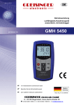
SD 300 pH
pH-Wert • pH Value
DE
Bedienungsanleitung
Seite 3 –27
GB
Instruction Manual
Page 28–53
www.lovibond.com
EG-Konformitätserklärung
Name des Herstellers:
Tintometer GmbH
Schleefstraße 8 - 12
44287 Dortmund
Deutschland
erklärt, dass dieses Produkt
SD 300 pH
Produktname:
den folgenden Normen entspricht, die in der Richtlinie des Rates zur Angleichung der
Rechtsvorschriften der Mitgliedstaaten über die elektromagnetische Verträglichkeit (2004/108/
EG) und der Niederspannungsrichtlinie (2006/95/EG) festgelegt sind.
Für die Beurteilung des Erzeugnisses hinsichtlich elektromagnetischer Verträglichkeit wurden
folgende Normen herangezogen:
EN 61326-1: 2006 (Tabelle 3, Klasse B)
EN 61326-1: 2006 (Anhang A, Klasse B)
Diese Erklärung wird verantwortlich für den Hersteller abgeben durch
Dortmund, 20. Januar 2013
Cay-Peter Voss, Geschäftsführer
DE
Inhaltsverzeichnis
1. Allgemeiner Hinweis. . . . . . . . . . . . . . . . . . . . . . . . . . . . . . . . . . . . . . . . . . . . . . 4
2. Sicherheit. . . . . . . . . . . . . . . . . . . . . . . . . . . . . . . . . . . . . . . . . . . . . . . . . . . . . . 4
2.1 Bestimmungsgemäße Verwendung. . . . . . . . . . . . . . . . . . . . . . . . . . . . . . . . . . . 4
2.2 Sicherheitszeichen und Symbole. . . . . . . . . . . . . . . . . . . . . . . . . . . . . . . . . . . . . 4
2.3 Sicherheitshinweise. . . . . . . . . . . . . . . . . . . . . . . . . . . . . . . . . . . . . . . . . . . . . . . 5
3. Produktbeschreibung. . . . . . . . . . . . . . . . . . . . . . . . . . . . . . . . . . . . . . . . . . . . . 6
3.1 Lieferumfang . . . . . . . . . . . . . . . . . . . . . . . . . . . . . . . . . . . . . . . . . . . . . . . . . . . 6
3.2 Betriebs- und Wartungshinweise. . . . . . . . . . . . . . . . . . . . . . . . . . . . . . . . . . . . . 6
4. Bedienung . . . . . . . . . . . . . . . . . . . . . . . . . . . . . . . . . . . . . . . . . . . . . . . . . . . . . 6
4.1. Anzeigeelemente. . . . . . . . . . . . . . . . . . . . . . . . . . . . . . . . . . . . . . . . . . . . . . . . 6
4.2. Bedienelemente. . . . . . . . . . . . . . . . . . . . . . . . . . . . . . . . . . . . . . . . . . . . . . . . . 7
4.3 Anschlüsse. . . . . . . . . . . . . . . . . . . . . . . . . . . . . . . . . . . . . . . . . . . . . . . . . . . . . 8
4.4Aufsteller. . . . . . . . . . . . . . . . . . . . . . . . . . . . . . . . . . . . . . . . . . . . . . . . . . . . . . 8
5. Inbetriebnahme . . . . . . . . . . . . . . . . . . . . . . . . . . . . . . . . . . . . . . . . . . . . . . . . . 9
6. Grundlagen zur Messung. . . . . . . . . . . . . . . . . . . . . . . . . . . . . . . . . . . . . . . . . . 9
6.1 pH-Messung. . . . . . . . . . . . . . . . . . . . . . . . . . . . . . . . . . . . . . . . . . . . . . . . . . . . 9
6.2 Redox-Messung . . . . . . . . . . . . . . . . . . . . . . . . . . . . . . . . . . . . . . . . . . . . . . . . 10
6.3 rH-Messung. . . . . . . . . . . . . . . . . . . . . . . . . . . . . . . . . . . . . . . . . . . . . . . . . . . 10
6.3.1 manuelle pH-Wert (und Temperatur-) Einstellung . . . . . . . . . . . . . . . . . . . . . . . 10
6.3.2 automatische pH-Wert Übernahme aus pH-Messung (nur bei deaktiviertem Logger). . . 11
6.4 Kalibrieren der pH-Messung. . . . . . . . . . . . . . . . . . . . . . . . . . . . . . . . . . . . . . . 11
6.4.1 Die automatische Temperaturkompensation bei der Kalibrierung . . . . . . . . . . . 11
6.4.2 Durchführung der Kalibrierung. . . . . . . . . . . . . . . . . . . . . . . . . . . . . . . . . . . . . 12
7. Konfiguration des Gerätes . . . . . . . . . . . . . . . . . . . . . . . . . . . . . . . . . . . . . . . . 14
8. Datenlogger. . . . . . . . . . . . . . . . . . . . . . . . . . . . . . . . . . . . . . . . . . . . . . . . . . . 19
8.1. Manuelle Aufzeichnung („Func-Stor“) . . . . . . . . . . . . . . . . . . . . . . . . . . . . . . . 19
8.2. Automatische Aufzeichnung mit einstellbarem Zyklus „Func CYCL“. . . . . . . . . 20
9. Universalausgang. . . . . . . . . . . . . . . . . . . . . . . . . . . . . . . . . . . . . . . . . . . . . . . 21
9.1. Schnittstelle . . . . . . . . . . . . . . . . . . . . . . . . . . . . . . . . . . . . . . . . . . . . . . . . . . . 21
9.2. Analogausgang . . . . . . . . . . . . . . . . . . . . . . . . . . . . . . . . . . . . . . . . . . . . . . . . 22
10. Justieren des Gerätes . . . . . . . . . . . . . . . . . . . . . . . . . . . . . . . . . . . . . . . . . . . . 22
11. GLP . . . . . . . . . . . . . . . . . . . . . . . . . . . . . . . . . . . . . . . . . . . . . . . . . . . . . . . . . 22
11.1. Kalibrier-Intervall (C.Int) . . . . . . . . . . . . . . . . . . . . . . . . . . . . . . . . . . . . . . . . . . 22
11.2. Kalibrier-Datenspeicher (rEAd CAL) . . . . . . . . . . . . . . . . . . . . . . . . . . . . . . . . . 23
12. Alarm („AL.“). . . . . . . . . . . . . . . . . . . . . . . . . . . . . . . . . . . . . . . . . . . . . . . . . . 23
13. Echtzeituhr („CLOC“). . . . . . . . . . . . . . . . . . . . . . . . . . . . . . . . . . . . . . . . . . . . 23
14. Batteriewechsel . . . . . . . . . . . . . . . . . . . . . . . . . . . . . . . . . . . . . . . . . . . . . . . . 24
15. Fehler- und Systemmeldungen . . . . . . . . . . . . . . . . . . . . . . . . . . . . . . . . . . . . . 25
16. Rücksendung und Entsorgung . . . . . . . . . . . . . . . . . . . . . . . . . . . . . . . . . . . . . 26
16.1Rücksendung. . . . . . . . . . . . . . . . . . . . . . . . . . . . . . . . . . . . . . . . . . . . . . . . . . 26
16.2Entsorgung. . . . . . . . . . . . . . . . . . . . . . . . . . . . . . . . . . . . . . . . . . . . . . . . . . . . 26
17. Technische Daten. . . . . . . . . . . . . . . . . . . . . . . . . . . . . . . . . . . . . . . . . . . . . . . 26
SD 300_pH_1 01/2013
3
1. Allgemeiner Hinweis
Lesen Sie dieses Dokument aufmerksam durch und machen Sie sich mit der Bedienung des
Gerätes vertraut, bevor Sie es einsetzen. Bewahren Sie dieses Dokument griffbereit und
in unmittelbarer Nähe des Geräts auf, damit Sie oder das Fachpersonal im Zweifelsfalle
jederzeit nachschlagen können.
Montage, Inbetriebnahme, Betrieb, Wartung und Außerbetriebnahme dürfen nur von
fachspezifisch qualifiziertem Personal durchgeführt werden. Das Fachpersonal muss die
Betriebsanleitung vor Beginn aller Arbeiten sorgfältig durchgelesen und verstanden haben.
Die Haftung und Gewährleistung des Herstellers für Schäden und Folgeschäden erlischt
bei bestimmungswidriger Verwendung, Nichtbeachten dieser Betriebsanleitung, Einsatz
ungenügend qualifizierten Fachpersonals sowie eigenmächtiger Veränderung am Gerät.
Der Hersteller haftet nicht für Kosten oder Schäden, die dem Benutzer oder Dritten durch
den Einsatz dieses Geräts, vor allem bei unsachgemäßem Gebrauch des Geräts oder bei
Missbrauch oder Störungen des Anschlusses oder des Geräts, entstehen.
Der Hersteller übernimmt keine Haftung bei Druckfehler.
2. Sicherheit
2.1 Bestimmungsgemäße Verwendung
Das Gerät ist für die Messung von pH und Redox-Potentialen - unter Verwendung von geeigneten Elektroden – ausgelegt. Der Elektrodenanschluss erfolgt über eine BNC-Buchse.
Bitte Beachten: für die pH- und Redox-Messung sind unterschiedliche Elektrodentypen
notwendig. Zusätzlich besteht die Möglichkeit, einen Temperaturfühler (Pt1000 oder NTC
30k, mit Bananensteckern) anzuschließen. Die gemessene Temperatur wird von der automatischen Temperaturkompensation (ATC) der pH, rH oder mVH-Messung verwendet und wird
zusätzlich angezeigt.
Die Sicherheitshinweise dieser Bedienungsanleitung müssen beachtet werden (siehe unten).
Das Gerät darf nur unter den Bedingungen und für die Zwecke eingesetzt werden, für die
es konstruiert wurde.
Das Gerät muss pfleglich behandelt und gemäß den technischen Daten eingesetzt werden
(nicht werfen, aufschlagen, etc.). Gerät vor Verschmutzung schützen.
2.2 Sicherheitszeichen und Symbole
Warnhinweise sind in diesem Dokument wie folgt gekennzeichnet:
!
1. Warnung! Symbol warnt vor unmittelbar drohender Gefahr, Tod,
schweren Körperverletzungen bzw. schweren Sachschäden bei
Nichtbeachtung.
2. Achtung! Symbol warnt vor möglichen Gefahren oder schädlichen
Situationen, die bei Nichtbeachtung Schäden am Gerät bzw. an der
Umwelt hervorrufen.
i
4
3. Hinweis! Symbol weist auf Vorgänge hin, die bei Nichtbeachtung
einen indirekten Einfluss auf den Betrieb haben oder eine nicht
vorhergesehene Reaktion auslösen können.
SD_300_pH_1 01/2013
2.3 Sicherheitshinweise
Dieses Gerät ist gemäß den Sicherheitsbestimmungen für elektronische Messgeräte gebaut und
geprüft. Die einwandfreie Funktion und Betriebssicherheit des Gerätes kann nur gewährleistet
werden, wenn bei der Benutzung die allgemein üblichen Sicherheitsvorkehrungen sowie die
gerätespezifischen Sicherheitshinweise dieser Betriebsanleitung beachtet werden.
1. Funktion und Betriebssicherheit des Gerätes können nur unter den klimatischen Verhältnissen, die im Kapitel "Technische Daten" spezifiziert sind, eingehalten werden.
Wird das Gerät von einer kalten in eine warme Umgebung transportiert kann durch
Kondensatbildung eine Störung der Gerätefunktion eintreten. In diesem Fall muss die
Angleichung der Gerätetemperatur an die Raumtemperatur vor einer Inbetriebnahme
abgewartet werden.
2.
Wenn anzunehmen ist, dass das Gerät nicht mehr gefahrlos betrieben werden
kann, so ist es außer Betrieb zu setzen und vor einer weiteren Inbetriebnahme
durch Kennzeichnung zu sichern. Die Sicherheit des Benutzers kann durch das
Gerät beeinträchtigt sein, wenn es z.B.
- sichtbare Schäden aufweist.
- nicht mehr wie vorgeschrieben arbeitet. - längere Zeit unter ungeeigneten Bedingungen gelagert wurde.
Im Zweifelsfall Gerät zur Reparatur oder Wartung an Hersteller schicken.
!
3. Konzipieren Sie die Beschaltung beim Anschluss an andere Geräte besonders sorgfältig.
Unter Umständen können interne Verbindungen in Fremdgeräten (z.B. Verbindung GND
mit Erde) zu nicht erlaubten Spannungspotentialen führen, die das Gerät selbst oder ein
angeschlossenes Gerät in seiner Funktion beeinträchtigen oder sogar zerstören können.
4.
5.
!
Dieses Gerät ist nicht für Sicherheitsanwendungen, Not-Aus Vorrichtungen
oder Anwendungen bei denen eine Fehlfunktion Verletzungen und materiellen
Schaden hervorrufen könnte, geeignet. Wird dieser Hinweis nicht beachtet,
könnten schwere gesundheitliche und materielle Schäden auftreten.
!
Dieses Gerät darf nicht in einer explosionsgefährdeten Umgebung eingesetzt werden. Bei Betrieb in explosionsgefährdeter Umgebung besteht
erhöhte Verpuffungs-, Brand-, oder Explosionsgefahr durch Funkenbildung.
SD 300_pH_1 01/2013
5
3. Produktbeschreibung
3.1 Lieferumfang
Im Standard-Lieferumfang enthalten:
- SD 300 pH mit 2 AAA-Batterien
- Betriebsanleitung
- Zusätzlich als Set im Koffer: Standard Pufferlösungen je 90 ml
Elektrode(n) pH/ Temperatur
3.2 Betriebs- und Wartungshinweise
1. Batteriebetrieb:
Wird in der unteren Anzeige ´bAt´ angezeigt, so sind die Batterien verbraucht und müssen erneuert werden. Die Gerätefunktion ist jedoch noch für eine gewisse Zeit gewährleistet.Wird in der
oberen Anzeige ´bAt´ angezeigt, so reicht die Batteriespannung für den Gerätebetrieb nicht mehr
aus, die Batterie ist nun ganz verbraucht. Batteriewechsel siehe Kapitel "14. Batteriewechsel".
Bei Lagerung des Gerätes bei über 50 °C Umgebungstemperatur muss die Batterie
entnommen werden. Wird das Gerät längere Zeit nicht benutzt, sollte die Batterie
herausgenommen werden. Die Uhrzeit muss nach Wiederinbetriebnahme jedoch
erneut eingestellt werden.
i
2. Gerät und Sensoren/Elektroden müssen pfleglich behandelt werden und gemäß
den technischen Daten eingesetzt werden (nicht werfen, aufschlagen, etc.). Stecker
und Buchsen sind vor Verschmutzung zu schützen.
3. USB:
Achten Sie beim Anschluss des USB-Schnittstellenkabels darauf, nur zulässige Komponenten
anzuschließen.
Empfohlen wird der Betrieb mit dem Schnittstellenkabel USB 300. Wird dieses
verwendet, versorgt sich dass Gerät aus der USB-Schnittstelle des verbundenen
PC’s oder USB-Netzteiladapters.
4. Anzeigewerte bei Kabelbruch oder keiner angeschlossenen pH- bzw. Redox-Elektrode:
Wird keine Elektrode angesteckt, oder ist das Anschlusskabel defekt, werden trotzdem entsprechende mV oder pH-Werte angezeigt. Diese stellen jedoch kein gültiges
Messergebnis dar!
4. Bedienung
4.1 Anzeigeelemente
3
rH
mV
mVH
4
°C
°F
atc stab cal logg
6
6
1
°C
MAX
HLD
DIF MIN
5
pH
7
8
pH
1. Hauptanzeige:pH-Wert, Redox-Wert (mV, mVH),
rH-Wert
2. Nebenanzeige: Messwert Temperatur
3. Anzeigepfeile für Messwert-Einheiten
2
4. Bewertung des Elektroden- bzw. Batteriezustandes
5. Anzeigeelemente zur Darstellung des minimalen / maximalen/gespeicherten Messwertes
9
SD_300_pH_1 01/2013
6. atc-Pfeil: zeigt im Betriebsmodus ’pH’, ’mVH’ bzw. ’rH’ an, ob ein
Temperaturfühler angesteckt ist, und somit die automatische Temperaturkompensation aktiv ist.
7. stab-Pfeil:signalisiert stabilen Messwert
8. cal-Pfeil: signalisiert im Betriebsmodus ’pH’,
dass sich das Gerät im Kalibrie-
rungsvorgang befindet.
9. logg-Pfeil:Logger ist bereit.
Pfeil blinkt: automatische Aufzeich
nung (Logg CYCL) ist aktiv.
4.2 Bedienelemente
Ein- / Ausschalter, Licht
kurz drücken: Beleuchtung aktivieren
bzw. Gerät einschalten
lang drücken: Gerät ausschalten
set / menu:
kurz drücken: bei ’pH’, ’rH’ und ’mVH: manuelle
Temperatureingabe, wenn kein Temperaturfühler angesteckt ist
zusätzlich bei ’rH’: manuelle Ein
gabe des pH-Wertes
2 sec. drücken (Menu): Aufruf der Konfiguration
min / max:
kurz drücken:Anzeige des minimalen bzw.
maximalen gemessenen Wertes
2 sec.drücken: Löschen des jeweiligen Wertes
cal: nur im Betriebsmodus ’pH’:
kurz drücken: Anzeige des Elektrodenzustandes
(Elektrodensymbol + Balkenan
zeige) 2 sec. drücken: Starten der pH-Kalibrierung
store / enter:
Logger aus: Halten und Speichern des aktuellen
Messwertes (’HLD’ in Display)
Logger an: Bedienung des Datenloggers –
Kap. Datenlogger
Set/Menu: Bestätigung von Eingaben, Rück
kehr zur Messung
SD 300_pH_1 01/2013
7
4.3 Anschlüsse
Universalausgang: Schnittstelle, Versorgung,
Analogausgang (siehe Kapitel 9.1, 9.2)
BNC-Buchse: Anschluss für pH- bzw. RedoxElektrode. Mit passendem Kabel wasserdicht
gemäß IP65!
Bananen-Buchsen:
Anschluss Pt1000- oder NTC 30k Temperaturfühler
Bei Elektroden mit integriertem Temperaturfühler wird der Bananenstecker außen angeschlossen.
Bei getrenntem Temperaturfühler wird dieser
an beiden Bananenbuchsen angeschlossen.
4.4 Aufsteller
Bedienung:
- Ziehen Sie an Beschriftung „open“, um Aufsteller auszuklappen.
- Ziehen Sie an Beschriftung „open“ erneut, um Aufsteller weiter auszuklappen.
Aufsteller zugeklappt
Aufsteller in Position 90°
Aufsteller in Position 180°
Funktionen:
- Das Gerät mit zugeklapptem Aufsteller kann flach auf Tisch gelegt werden oder an einem
Gürtel oder ähnlichem aufgehängt werden.
- Das Gerät mit Aufsteller in Position 90° kann am Tisch oder ähnlichem aufgestellt werden
- Das Gerät mit Aufsteller in Position 180° kann beispielsweise an einer Schraube aufgehängt
werden.
Gerät an einem Gürtel
Gerät am Tisch aufgestellt
aufgehängt
8
Gerät an Schraube aufgehängt
SD_300_pH_1 01/2013
5. Inbetriebnahme
Elektroden verbinden, Gerät mit der Taste
Nach dem Segmenttest
einschalten.
zeigt das Gerät kurz Informationen zu seiner Konfiguration an:
falls eine Nullpunkt- oder Steigungskorrektur vorgenommen wurde
(siehe Kapitel 7. Konfiguration des Gerätes)
Schutzkappe von der Elektrode abnehmen. (Vorsicht: Kappe soll KCL 3 M oder Aufbewahrungslösung enthalten).
Danach ist das Gerät bereit zur Messung.
6. Grundlagen zur Messung
6.1 pH-Messung
Der pH-Wert beschreibt das saure oder alkalische Verhalten einer wässrigen Lösung.
pH-Werte unter 7 sind sauer (je kleiner desto saurer), Werte über 7 gelten als alkalisch, pH
7 = neutral.
Er errechnet sich aus dem negativen dekadischen Logarithmus der Wasserstoffionen-Aktivität
(diese ist oft näherungsweise gleich der Wasserstoffionen-Konzentration):
) ∙ f(H )
(c(H(1 mol/l)
) mit +
pH Wert = -log10
+
c(H+): Wasserstoffionenkonzentration in mol/l
f(H +): Aktivitätskoeffizient der Wasserstoffionen
(meist kleiner 1)
Die Abkürzung „pH“ steht für pondus Hydrogenii (lateinisch pondus: „Gewicht“; Hydrogenium: „Wasserstoff“).
Um den pH-Wert einer Lösung zu registrieren, sollte dieser immer mit der Messtemperatur
zusammen erfasst werden, Bsp.:
pH 5.87; 22.8 °C.
Grund: Die meisten Flüssigkeiten verändern ihren pH-Wert mit der Temperatur.
Die pH-Messung ist eine sehr präzise aber auch empfindliche Messung. Die gemessenen
Signale sind sehr schwach (hochohmig), besonders wenn in schwachen/ionenarmen Medien
gemessen wird. Es ist deshalb darauf zu achten, dass
- Störungen (elektrostatische Aufladungen etc.) vermieden werden,
- durch langsames Rühren ein stabiler Messwert erreicht wird,
- Steckkontakte trocken und sauber gehalten werden,
- Elektroden (außer spezielle wasserdichte Ausführungen) möglichst nicht länger über den
Schaft hinaus untergetaucht werden,
- die Elektrode ausreichend oft kalibriert wird (s.u.) (Die Kalibrierhäufigkeit ist abhängig von
der Elektrode und der Anwendung und kann zwischen jeder Stunde und mehreren Wochen
liegen),
- eine geeignete Elektrode verwendet wird.
SD 300_pH_1 01/2013
9
6.2 Redox-Messung
Das Redox-Potential (oder: ORP) gibt an, inwieweit die gemessene Probe eine oxidierende
beziehungsweise reduzierende Wirkung im Bezug zur Wasserstoffnormalelektrode hat.
Dieses Potential wird häufig in Schwimmbädern als Messgröße für die Desinfektionswirkung
einer Chlorung herangezogen. Für Aquarianer ist der Redox-Wert ebenfalls ein wichtiger
Parameter, da Fische nur innerhalb eines bestimmten Redox-Bereich leben können. Auch in
Trinkwasseraufbereitung, Gewässerüberwachung und in der Industrie spielt der Messwert
eine wichtige Rolle.
Die Messung erfolgt mit den verbreiteten Silber/Silberchlorid Elektroden (Bezugssystem mit
3 molarer Kaliumchloridlösung). Sie kann direkt abgelesen werden (Einstellung mV) oder mit
der Einstellung Unit mVH automatisch und temperaturkompensiert auf das „Bezugssystem
Wasserstoffnormalelektrode“ umgerechnet werden.
Ein Kalibrieren vergleichbar mit der pH-Messung erfolgt bei der Redox-Messung nicht. Die
Tauglichkeit der Elektroden kann allerdings jederzeit mit Redox-Prüflösungen überprüft werden.
6.3 rH-Messung
Der rH-Wert ist ein berechneter Wert aus einer pH und einer Redox-Messung. Er wird beispielsweise verwendet, um die antioxidative Kraft von Lebensmitteln zu beschreiben. Dieses
ist ein Maß für die Fähigkeit von Lebensmitteln schädliche freie Radikale zu reduzieren (Bioelektronik nach Prof. Vincent).
Um den rH-Wert Ihrer Lösung festzustellen gehen Sie wie folgt vor:
6.3.1 manuelle pH-Wert (und Temperatur-) Einstellung
Die Messwerte für pH und Temperatur (falls kein Temperaturfühler angeschlossen ist) können
manuell eingegeben werden. Betätigen Sie dazu kurz die Taste
und geben Sie mit den
Tasten
bzw.
den Temperaturwert ein. Nach nochmaligem kurzem Drücken der
Taste kann der pH-Wert verändert werden. (siehe auch manuelle Einstellung der Temperatur),
die Eingabe wird mit
10
bestätigt.
SD_300_pH_1 01/2013
6.3.2 automatische pH-Wert Übernahme aus pH-Messung (nur bei
deaktiviertem Logger)
i
Achten Sie während den Messungen immer darauf, dass Ihre pH- und RedoxElektroden in gutem Zustand sind und vor dem Einbringen in die Lösung gründlich
gereinigt und getrocknet wurden.
Stellen Sie zunächst die pH-, die Redox-Elektrode und den Temperaturfühler in die Lösung
und rühren Sie vorsichtig um.
1. Messen des pH-Wertes:
Stecken Sie die pH-Elektrode und den Temperaturfühler an das Gerät an.
Stellen Sie anschließend das Gerät zunächst auf pH-Messung und führen Sie bei Bedarf
eine Kalibrierung der Elektrode durch (siehe 6.4 „Kalibrieren der pH-Messung“ und 7
„Konfiguration des Gerätes“).
Anschließend messen Sie den pH-Wert der Lösung und speichern den Messwert mit der
Taste "enter"
ab. Schalten Sie das Gerät bis zum Abschluss der rH-Messung nicht
ab, da ansonsten der pH-Wert gelöscht wird und per Hand eingegeben werden muss.
2. Feststellung des rH-Wertes:
Stecken Sie nun die Redox-Elektrode an und konfigurieren das SD 300 pH auf rH-Messung.
In der Hauptanzeige erscheint nun der rH-Wert der Lösung, in der Nebenanzeige werden
abwechselnd der zuvor gemessene pH-Wert und die Temperatur angezeigt.
6.4Kalibrieren der pH-Messung
Die Elektrodendaten von pH-Elektroden sind durch Alterung und Exemplarstreuung großen
Schwankungen unterworfen. Deswegen ist vor einer Messung eine Kontrolle der aktuellen
Kalibrierung mit Pufferlösungen nötig, bei Abweichungen muss eine Neukalibrierung vorgenommen werden. (siehe auch Kapitel 11 GLP)
Pufferlösungen sind Flüssigkeiten, die einen exakten pH-Wert aufweisen. Zur Kalibrierung
können folgende Puffer verwendet werden:
- Standard-Serie (im Lieferumfang "Set" enthalten)
- DIN-Serie (CAL dIn; pH 1.68 (A), pH 4.01 (C), pH 6.87 (D), pH 9.18 (F) und pH 12.45 (G))
- beliebige Puffer (CAL Edit; neutraler Puffer im Bereich 6,5 ... 7,5pH).
Die Lebensdauer der Pufferlösungen ist begrenzt und wird u.a. durch unzureichendes
Spülen und Trocknen beim Wechsel zwischen Lösungen stark verkürzt. Dies kann zu
Fehlkalibrierungen führen! Deshalb zur Kalibrierung möglichst frische Pufferlösungen
verwenden, Spülen mit entionisiertem oder destilliertem Wasser!
i
6.4.1 Die automatische Temperaturkompensation bei der Kalibrierung
Sowohl das Signal der pH-Elektrode, als auch pH-Puffer sind temperaturabhängig. Falls ein
Temperaturfühler angeschlossen ist wird der Temperatureinfluss der Elektrode sowohl beim
Messen als auch bei der Kalibrierung vollautomatisch kompensiert. Andernfalls sollte die
tatsächliche Temperatur des jeweiligen Puffers möglichst genau eingegeben werden (s.u.).
Wird mit der Standard- bzw. mit der DIN-Puffer Serie gearbeitet, werden zusätzlich auch die
Temperatureinflüsse der Puffer kompensiert. Bei manueller Pufferwahl sollten die pH-Werte
der Puffer bei der zugehörigen Temperatur eingegeben werden, um eine möglichst genaue
Kalibrierung zu erreichen.
SD 300_pH_1 01/2013
11
6.4.2 Durchführung der Kalibrierung
Bitte Beachten: Eine Kalibrierung kann nur im Temperaturbereich von 0 - 60 °C
durchgeführt werden!
Falls noch nicht geschehen, Messfunktion ’pH’ wählen, je nach Bedarf die 1-, 2- oder die
3-Punktkalibrierung und die entsprechende Pufferserie (Std, Edit oder din) aktivieren
(siehe 7 „Konfiguration des Gerätes“).
Vorsichtig die Schutzkappe von der Elektrode abziehen (Vorsicht! Enthält 3 M KCl!).
Elektrode mit destilliertem Wasser abspülen und abtrocknen.
Start der Kalibrierung:
-Taste 2 sec. lang gedrückt halten.
In der Anzeige erscheint die Aufforderung zum Messen der 1.Kalibrierlösung. Die Kalibrierung
kann mit der
-Taste jederzeit abgebrochen werden. In diesem Fall bleibt die vorhergehende Kalibrierung gültig.
1. Kalibrierpunkt 1: ’Pt. 1’
*1)
Stellen Sie die Elektrode und
den Temperaturfühler (falls
vorhanden) in die neutrale
Lösung und rühren Sie vorsichtig um.
(Bei 1-Punkt-Kalibrierung
kann eine beliebige Lösung
(bspw. pH 4) verwendet
werden)
Sobald ein stabiler Messwert
ermittelt wurde, fährt das
Gerät mit dem nächsten
Punkt fort.
ohne Temperaturfühler:
manuelle Eingabe Temperatur Puffer 1
Geben Sie mit den Tasten:
die Puffertemperatur ein.
oder
Mit
wird der Wert übernommen
und der nächste Kalibrierungsschritt wird
angezeigt
Bei der 1-Punkt-Kalibrierung ist die Kalibrierung bereits beendet, mit der linken Balken-Anzeige
wird der Elektrodenzustand signalisiert.
2. Spülen der Elektrode mit destilliertem bzw. entionisiertem Wasser, Trocknen
3. Kalibrierpunkt 2: ’Pt. 2’ (nur bei 2 oder 3-Punkt-Kalibrierung)
Stellen Sie die Elektrode
ohne Temperaturfühler:
und den Temperaturfühmanuelle Eingabe Tempeler (falls vorhanden) in die
ratur Puffer 2
zweite Puffer-Lösung. (z.B.
bei Standard-Serie: pH 4.01
oder pH 10.01) und rühren Geben Sie mit den Tasten:
oder
Sie vorsichtig um.
die Puffertemperatur ein.
*1)
12
Sobald ein stabiler Messwert
wird der Wert übernommen
ermittelt wurde, fährt das Mit
Gerät mit dem nächsten und der nächste Kalibrierungsschritt wird
angezeigt
Punkt fort.
SD_300_pH_1 01/2013
Bei der 2-Punkt-Kalibrierung ist die Kalibrierung bereits beendet, mit der linken Balken-Anzeige
wird der Elektrodenzustand signalisiert.
4. Spülen der Elektrode mit destilliertem bzw. entionisiertem Wasser, Trocknen
5. Kalibrierpunkt 3: ’Pt. 3’ (nur bei 3-Punkt-Kalibrierung)
Bitte beachten Sie, dass bei einer 3-Punkt-Kalibrierung sowohl ein saurer als auch
ein alkalischer Kalibrierungspunkt notwendig ist.
*1)
Stellen Sie die Elektrode
ohne Temperaturfühler:
und den Temperaturfühler
manuelle Eingabe Tempe(falls vorhanden) in die dritte
ratur Puffer 3
Puffer-Lösung. (z.B. bei Standard-Serie: pH 10.01) und
rühren Sie vorsichtig um.
Geben Sie mit den Tasten:
oder
die Puffertemperatur ein.
Sobald ein stabiler Messwert
ermittelt wurde, fährt das
wird der Wert übernommen
Gerät mit dem nächsten Mit
und der nächste Kalibrierungsschritt wird
Punkt fort.
angezeigt
Die Kalibrierung ist beendet, mit der linken Balken-Anzeige wird der Elektrodenzustand
signalisiert.
*1) Bei manueller Puffereinstellung (CAL Edit) muss mit den Tasten
oder
der
pH-Wert der Lösung eingegeben werden. Bei Lösungen der Standard- und DIN-Serie wird der
pH-Wert der jeweiligen Lösung automatisch erkannt.
Mit
wird der Wert übernommen und der nächste Kalibrierungsschritt wird angezeigt
SD 300_pH_1 01/2013
13
Fehlermeldungen der pH-Kalibrierung:
neutraler Puffer ist unzulässig:
- Elektrode ist defekt
- falsche Pufferlösung
- Pufferlösung defekt
Reinigung der Elektrode,
nochmals Kalibrieren. falls
wiederum Fehler -> Elektrode austauschen
immer den neutralen Puffer
als erste Lösung verwenden! (Ausnahme: 1 PunktKalibrierung)
frische Pufferlösung verwenden
Steilheit ist zu gering:
- Elektrode ist defekt
- Pufferlösung defekt
Elektrode austauschen
frische Pufferlösungen verwenden
Steilheit ist zu groß:
- Elektrode ist defekt
- Pufferlösung defekt
Elektrode austauschen
frische Pufferlösungen verwenden
falsche Kalibrierungstemperatur
Kalibrierung ist nur im Bereich von 0 ... 60 °C möglich
zulässige Elektrodendaten:
Asymmetrie: ±55 mV
Steilheit: -62...-45 mV/pH
7. Konfiguration des Gerätes
i
Einige Menüpunkte sind abhängig von der aktuellen Geräteeinstellung zugänglich
(z.B. sind einige gesperrt wenn Logger Daten enthält).
Zum Konfigurieren 2 Sekunden lang „menu“
anzeige „SEt“) aufgerufen. Mit „menu“
mit Taste
14
wählen Sie den gewünschten Menüzweig,
können Sie zu den zugehörigen Parametern springen, die Sie dann verändern
können (Auswahl der Parameter mit
i
drücken, dadurch wird das Menü (Haupt-
).
Die Einstellung der Parameter erfolgt mit den Tasten
Drücken von „menu“
bzw.
. Erneutes
wechselt zurück zum Hauptmenü und speichert die
wird die Konfiguration beendet. Werden die Tasten
Einstellungen. Mit
‚menu‘ und ‚store‘ gemeinsam länger als 2 Sekunden gedrückt, werden die Werkseinstellungen wiederhergestellt Befinden sich Daten im Einzelwertlogger
(Logger: ‘Func Stor’) wird als erstes Menü ‘rEAd Logg’ angezeigt: siehe dazu auch Kapitel 8
Datenlogger. Wird länger als 2 Minuten keine Taste gedrückt, wird die Konfiguration
abgebrochen. Bis dahin gemachte Änderungen werden nicht gespeichert!
SD_300_pH_1 01/2013
Menü
Parameter
Werte
Bedeutung
rEAd Logg: Lesen der Einzel-Loggerdaten,
siehe Kapitel 8!
Set Configuration: Allgemeine Einstellungen
Input: Auswahl der Messgröße
Pfeil „rH“
Messung des rH Wertes
Pfeil „mV“
Messung des mV Wertes (REDOX
bzw. ORP)
Pfeil „mVH“
Messung des mV Wertes bezogen
auf Wasserstoffsystem
Pfeil „pH“
Messung des pH Wertes
**
Resolution pH: Auflösung der pH-Anzeige
0.1 ... 0.001
Zehntel pH … Tausendstel pH
Kalibrierung: Auswahl der Anzahl der Kalibrierpunkte
1-Pt
1-Punkt (nur Offset-Kalibrierung,
Steigung -59.2mV/pH)
2-Pt
2-Punkt (neutraler + ein weiterer
Puffer)
3-Pt
3-Punkt (neutraler + ein saurer +
ein weiterer Puffer)
Kalibrierung: Auswahl der Pufferserie
Std
Standard Puffer Serie (pH 7, pH
4, pH 10) im Lieferumfang "Set"
enthalten
din
DIN 19266-Pufferserie pH 1.68(A),
pH 4.01(C), pH 6.87(D), pH 9.18(F),
pH 12.45(G)
Edit
beliebige Puffer, manuelle Einstellung
Kalibrierung: Zeitintervall für Kalibrierungserinnerung (Werkseinstellung: 30)
1 … 365
Zeitintervall für Kalibrierungserinnerung (in Tagen)
oFF
Keine Kalibrierungserinnerung
Einheit t: Auswahl der Temperatureinheit
SD 300_pH_1 01/2013
°C
Alle Temperaturangaben in Grad
Celsius
°F
Alle Temperaturangaben in Grad
Fahrenheit
**
15
Menü
Parameter
Werte
Bedeutung
Auto Hold: Automatische Messwertermittlung
(nur bei Logger = oFF wirksam)
on
Automatische Messwertermittlung
(nur bei Logger = oFF) Auto Hold
oFF
Standard-Holdfunktion auf Tastendruck (nur bei Logger = oFF)
Auto Power-Off : Automatische Geräteabschaltung.
1 ... 120
Abschaltverzögerung in Minuten.
Wird keine Taste gedrückt und
findet kein Datenverkehr über die
Schnittstelle statt, schaltet sich
das Gerät nach Ablauf dieser Zeit
automatisch ab
oFF
automatische Abschaltung deaktiviert (Dauerbetrieb)
Hintergrundbeleuchtung
oFF:
Keine Beleuchtung
5 … 120
Beleuchtung nach 5.. 120 s automatisch abschalten (Werkseinst.:
5 s)
on:
Beleuchtung immer an
Universeller Ausgang
16
SEr:
serielle Schnittstelle aktiviert
dAC:
Analogausgang aktiviert
oFF
Schnittstelle und Analogausgang
aus -> minimaler Stromverbrauch
01,11 ... 91
Basisadresse des Gerätes für serielle
Schnittstellenkommunikation.
z.B.
-2.00 ...
14.00 pH
Eingabe der Messwertes bei welchem der Analogausgang 0V ausgeben soll, z.B. bei 0,00 pH
z.B.
-2.00 ...
14.00 pH
Eingabe des Messwertes bei welcher der Analogausgang 1V ausgeben soll, z.B. bei 14,00 pH
SD_300_pH_1 01/2013
Set Corr: Justage der Messungen
Nullpunktkorrektur/Offset der Spannungsmessung
oFF
keine Nullpunktkorrektur der Spannungsmessung
-10.0 … 10.0
mV
Nullpunktkorrektur der Spannungsmessung in mV
Steigungskorrektur der Spannungsmessung
oFF
keine Steigungskorrektur der Spannungsmessung
-5.000 …
5.000 %
Steigungskorrektur der Spannungsmessung in %
**
**
**
Nullpunktkorrektur/Offset der Temperatur- **
messung
oFF
keine Nullpunktkorrektur der Temperaturmessung
-5.0 …
5.0°C
Nullpunktkorrektur der Temperaturmessung in °C
Steigungskorrektur der Temperaturmessung
oFF
keine Steigungskorrektur der Temperaturmessung
-5.00 ...
5.00%
Steigungskorrektur der Temperaturmessung in %
**
Set Alarm: Einstellung der Alarmfunktion
On / No.So
Messkanal pH/mV/rH: Alarm an mit
Hupe / Alarm an ohne Hupe
OFF
keine Alarmfunktion für Messkanal
pH/mV/rH
z.B.
Min-Alarm-Grenze pH/mV/rH (nicht
- 2 . 0 0 . . . bei AL. 1. oFF)
14.00 pH
z.B.
Max-Alarm-Grenze pH/mV/rH
-2.00..14.00 (nicht bei AL. 1. oFF)
pH
SD 300_pH_1 01/2013
On / No.So
Alarm Temperaturmessung an mit
Hupe / Alarm an ohne Hupe
OFF
keine Alarmfunktion für Temperaturmessung
-10.0 ...
+110.0 °C
Min-Alarm-Grenze Temperatur
(nicht bei AL. 2. oFF)
-10.0 ...
+110.0 °C
Max-Alarm-Grenze Temperatur
(nicht bei AL. 2. oFF)
17
Set Logger: Einstellung der Loggerfunktion
**
Auswahl der Loggerfunktion
*
CYCL
Cyclic: Loggerfunktion zyklischer
Logger
Stor
Store: Loggerfunktion
Einzelwertlogger
oFF
keine Loggerfunktion
0:01... 60:00 Zykluszeit in [Minuten:Sekunden]
bei zyklischem Logger
**
Set Clock: Einstellen der Echtzeituhr
HH:MM
Clock: Einstellen der Uhrzeit
Stunden:Minuten
YYYY
Year: Einstellen der Jahreszahl
TT.MM
Date: Einstellen des Datums
Tag.Monat
rEAd CAL: Lesen der Kalibrierdaten:
siehe Kapitel 11.2 Kalibrier-Datenspeicher (rEAd CAL)
(*) Sind Daten im Loggerspeicher, können mit (*) gekennzeichnete Parameter nicht
aufgerufen werden. Sollen diese verändert werden, müssen zunächst die Daten
gelöscht werden!
(**) Bei laufendem Logger können Parameter, die mit (**) gekennzeichnet sind nicht
aufgerufen werden.
18
SD_300_pH_1 01/2013
8. Datenlogger
Das Gerät besitzt zwei verschiedene Loggerfunktionen:
„Func-Stor“: manuelle Messwertaufzeichnung per Tastendruck „store“
Zusätzlich wird eine Messstelleneingabe (L-Id) gefordert.
„Func-CYCL“: automatische Aufzeichnung im Abstand der eingestellten Zykluszeit
Der Logger zeichnet jeweils 2 Messergebnisse pro Datensatz auf.
Ein Datensatz besteht aus: Messwert pH, mV, mVH oder rH
Messwert Temperatur
Messstelle L-Id (nur bei „Func-Stor“)
Uhrzeit und Datum zum Zeitpunkt des Speicherns
Zur Auswertung und Übertragung der Daten benötigen sie die Software GSOFT3050 (mind.
V3.0), mit der die Loggerfunktion sehr einfach gestartet und eingestellt werden kann.
Bei aktivierter Loggerfunktion (Func Stor oder Func CYCL) steht die Hold Funktion nicht zur
Verfügung, die Taste „store“ ist dann für die Loggerbedienung zuständig.
8.1 Manuelle Aufzeichnung („Func-Stor“)
a) Messwerte manuell aufzeichnen:
Wurde die Loggerfunktion „Func Stor“ gewählt (siehe „Konfigurieren des Gerätes“), können
maximal 1000 Messungen manuell abgespeichert werden:
kurz drücken: Datensatz wird abgespeichert (es wird kurz „St. XX“ angezeigt.
XX ist Nummer des Datensatzes)
Messstelleneingabe „L-Id“: Auswahl der Messstelle über Tasten
Zahl von 0…19999.
Die Eingabe wird mit
oder
.
bestätigt.
Falls der Loggerspeicher voll ist, erscheint
b) Manuelle Aufzeichnung abrufen:
Abgespeicherte Datensätze können sowohl mit der PC-Software GSOFT3050 ausgelesen, als
auch in der Geräteanzeige selbst betrachtet werden.
i
2 Sekunden lang drücken: Im Display erscheint:
„rEAd LoGG“ erscheint nur, wenn bereits Datensätze abgespeichert
worden sind! Ohne Datensätze erscheint das Konfigurationsmenü
Kurz drücken: Wechsel zwischen Messwerten, Messstelle- und Datum+Uhrzeit-Anzeige des Datensatzes
oder
Wechsel zwischen den Datensätzen
Anzeige der Aufzeichnungen beenden
SD 300_pH_1 01/2013
19
c) Manuelle Aufzeichnung löschen:
Sind bereits Daten gespeichert, können diese über die Store-Taste gelöscht werden:
2 Sekunden lang drücken: Aufruf des Lösch-Menüs
Wechsel der Auswahl:
oder
.
nichts löschen (Vorgang abbrechen)
Alle Datensätze löschen
den zuletzt aufgezeichneten Datensatz löschen
Bestätigung der Auswahl, Ende des Lösch-Menü
8.2 Automatische Aufzeichnung mit einstellbarem Zyklus „Func
CYCL“
Wurde die Loggerfunktion „Func CYCL“ gewählt (siehe „Konfiguration des Gerätes“) werden
nach Start des Loggers automatisch Messwerte im Abstand der eingestellten Zykluszeit aufgezeichnet. Die Logger-Zykluszeit ist einstellbar von 1 s bis 60 min (siehe „Konfiguration des Gerätes“).
Speicherbare Datensätze: 10000
a) Loggeraufzeichnung starten:
2 Sekunden lang drücken: Startauswahl, danach nochmals
: automatische
Aufzeichnung wird gestartet.
Jeder Speichervorgang wird durch kurze Anzeige von ‘St.XXXXX‘ signalisiert.
XXXXX steht hierbei für die Nummer des Datensatzes. Falls der Loggerspeicher voll ist, wird die Aufzeichnung automatisch gestoppt. In der Anzeige erscheint
b) Loggeraufzeichnung stoppen:
2 Sekunden lang drücken: : Falls eine Aufzeichnung läuft, erscheint das Stopp
Menü
Wechsel der Auswahl:
20
oder
.
Die Aufzeichnung nicht stoppen (Vorgang abbrechen)
Aufzeichnung stoppen
Bestätigung der Auswahl, Ende des Lösch-Menü
SD_300_pH_1 01/2013
i
Wird versucht ein mit zyklischer Aufzeichnung laufendes Gerät auszuschalten, wird
automatisch nachgefragt, ob die Aufzeichnung gestoppt werden soll.
Nur bei gestoppter Aufzeichnung kann das Gerät abgeschaltet werden.
Die Auto-Power-Off Funktion ist bei laufender Aufzeichnung deaktiviert!
c) Loggeraufzeichnung löschen:
2 Sekunden lang drücken: Falls Loggerdaten vorhanden sind, und die Aufzeichnung
bereits gestoppt wurde, erscheint das Lösch-Menü
Wechsel der Auswahl:
.
nichts löschen (Vorgang abbrechen)
oder
Alle Datensätze löschen
den zuletzt aufgezeichneten Datensatz löschen
Bestätigung der Auswahl, Ende des Lösch-Menü
9. Universalausgang
Der Ausgang kann entweder als serielle Schnittstelle (für USB 300 Schnittstellenadapter) oder
als Analogausgang (0-1V) verwendet werden. Wird der Ausgang nicht benötigt, sollte er
deaktiviert werden (Out oFF), da sich dadurch der Batterieverbrauch stark reduziert.
Wird das Gerät mit dem universellen Schnittstellenadapter USB 300 betrieben, versorgt sich
das Gerät aus dieser Schnittstelle.
Steckerbelegung:
4: externe Versorgung +5V, 50mA
3: GNDNur geeignete Adapterkabel
2: TxD/RxD (3.3V Logik)
sind zulässig (Zubehör)!
1: +UDAC, Analogausgang
9.1 Schnittstelle
Mit einem galv. getrennten Schnittstellenwandler USB 300 (Zubehör) kann das Gerät direkt
an eine USB-Schnittstelle eines PC angeschlossen werden. Die Übertragung erfolgt in einem
binär codierten Format und ist durch aufwendige Sicherheitsmechanismen gegen Übertragungsfehler geschützt (CRC).
Folgendes Standard - Softwarepaket steht zur Verfügung:
GSOFT3050: Bedien- und Auswertesoftware für die integrierte Loggerfunktion
SD 300_pH_1 01/2013
21
Das Messgerät besitzt 2 Kanäle:
- Kanal 1: Istwert-Kanal pH, mV oder rH und Basisadresse
- Kanal 2: Temperaturwert
Die über die Schnittstelle ausgegebenen Mess-/ Alarm-/ Bereichswerte werden immer
in der eingestellten Anzeigeeinheit ausgegeben!
i
9.2 Analogausgang
An der Universal-Ausgangsbuchse kann eine Analogspannung von 0-1V abgegriffen werden
(Einstellung Out dAC).
Mit DAC.0 und DAC.1 kann der Analogausgang sehr einfach skaliert werden.
Es ist darauf zu achten, dass der Analogausgang nicht zu stark belastet wird, da sonst der
Ausgangswert verfälscht werden kann und die Stromaufnahme des Gerätes entsprechend
steigt. Belastungen bis ca. 10 kOhm sind unbedenklich.
Überschreitet die Anzeige den mit DAC.1 eingestellten Wert, so wird 1V ausgegeben
Unterschreitet die Anzeige den mit DAC.0 eingestellten Wert, so wird 0V ausgegeben.
Im Fehlerfall (Err.1, Err.2, usw.) wird am Analogausgang eine Spannung leicht über 1V ausgegeben.
10. Justieren des Gerätes
Mit Offset und Scale können die Messeingänge justiert werden, sowohl Spannungsmessung
als auch Temperaturmessung. Voraussetzung: Es stehen zuverlässige Referenzen zur Verfügung
(z.B. Eiswasser, geregelte Präzisionswasserbäder o.ä.):
Wird eine Justierung vorgenommen (Abweichung von Werkseinstellung) wird dies beim
Einschalten des Gerätes mit der Meldung „Corr“ signalisiert.
Standardeinstellung der Nullpunkt und Steigungswerte ist: 'off' = 0.0, d.h. es wird keine
Korrektur vorgenommen.
Nur Offsetkorrektur:
Angezeigter Wert = gemessener Wert – Offset
Offset und Steigungskorrektur:
Anzeige = (gemessener Wert – OFFS) * (1 + SCAL / 100)
(Anzeige °F = (gemessener Wert °F - 32°F - OFFS) * (1 + SCAL / 100 ))
11. GLP
Zur GLP (Guten Labor Praxis) gehört die regelmäßige Überwachung des Gerätes und des
Zubehörs. Bei pH-Messungen muss insbesondere die korrekte pH-Kalibrierung sichergestellt
werden. Das Gerät unterstützt Sie dabei mit den im folgenden genannten Funktionen.
Voraussetzung für die Anwendung der GLP-Funktionen ist, dass die Elektrode nicht gewechselt
wird. Die Daten sind im Gerät gespeichert, beziehen sich allerdings auf die jeweilige Elektrode.
11.1 Kalibrier-Intervall (C.Int)
Sie können ein festes Intervall eingeben, mit dem das Gerät Sie automatisch daran erinnert, dass
eine neue Kalibrierung durchgeführt werden soll, bzw. die Kalibrierung nicht mehr gültig ist.
Die Länge des Intervalls ist dabei abhängig von Ihrer Anwendung und der Stabilität der Elektrode. Sobald das Intervall abgelaufen ist, blinkt in der Anzeige „CAL“.
22
SD_300_pH_1 01/2013
11.2 Kalibrier-Datenspeicher (rEAd CAL)
Die letzten 16 Kalibrierungen mit Datum und Ergebnissen sind im Gerät hinterlegt und können
abgerufen werden.
Kalibrierungsdatenspeicher anzeigen:
Abgespeicherte Kalibrierungsdaten können sowohl mit der PC-Software GSOFT3050 ausgelesen, als auch in der Geräteanzeige selbst betrachtet werden:
2 Sekunden lang drücken:
Im Display erscheint:
So oft drücken bis erscheint:
oder
(Konfigurationsebene)
read cal. = „Kalibrierungsdaten lesen“
Kurz drücken: Wechsel zwischen
- U.ASY = Asymmetriespannung in mV
- SL. 1 = Steigung sauer in mV/pH *1)
- SL. 2 = Steigung alkalisch in mV/pH *1)
- Datum+Uhrzeit-Anzeige des Datensatzes
Parallel wird über die Balkenanzeige die Elektrodenbewertung der
entspr. Kalibrierung gezeigt
oder
Wechsel zwischen den Kalibrierungs-Datensätzen
Anzeige der Kalibrierungs-Datensätze beenden
*1) Bei der 1-Punkt-Kalibrierung wird die Steigung sauer = Steigung alkalisch = -59.16 mV/pH
angenommen.
Bei einer 2-Punkt Kalibrierung ist die Steigung sauer = Steigung alkalisch.
Bei 3-Punkt-Kalibrierung werden unabhängige Werte für sauer und alkalisch ermittelt.
12. Alarm („AL.“)
Es sind 3 Einstellungen möglich:
aus (AL.oFF), an mit Hupe (AL.on), an ohne Hupe (AL.no.So).
In folgenden Fällen wird bei aktiver Alarmfunktion (on oder no.So) Alarm gegeben:
- untere Alarmgrenze (AL. Lo) unterschritten
- obere Alarmgrenze (AL. Hi) überschritten.
-Sensorfehler
- schwache Batterie (bAt)
- Err.7: Systemfehler (wird immer mit Hupe gemeldet)
Im Alarmfall wird bei Schnittstellenzugriffen das ‚PRIO‘-Flag in der Geräteantwort gesetzt.
13. Echtzeituhr („CLOC“)
Die Echtzeituhr wird für die zeitliche Zuordnung der Loggerdaten und der Kalibrierzeitpunkte
benötigt. Kontrollieren Sie deshalb bei Bedarf die Einstellungen.
SD 300_pH_1 01/2013
23
14. Batteriewechsel
Lesen Sie vor dem Batteriewechsel die nachfolgende Anleitung, und befolgen Sie diese anschließend Schritt für Schritt. Bei Nichtbeachtung kann es zu Beschädigungen des Gerätes
kommen, oder der Schutz gegen das Eindringen von Feuchtigkeit kann beeinträchtigt werden!
Unnötiges Aufschrauben des Gerätes ist zu vermeiden!
1. Schrauben der Schutzarmierung lösen und Schutzarmierung entfernen.
2. Die drei Kreuzschlitzschrauben an der Rückseite
des Gerätes herausschrauben.
3. Noch geschlossenes Gerät so ablegen, dass
Anzeige sichtbar bleibt.
Das Geräteunterteil inklusive Elektronik sollte
während des gesamten Batteriewechsels so
liegen bleiben.
Damit wird vermieden, dass die 3 Dichtungsringe,
die sich in den Schraubenlöchern befinden,
herausfallen.
4. Obere Gehäusehälfte abheben. Dabei ist beson
ders auf die 6 Funktionstasten zu achten, damit
diese nicht beschädigt werden.
5. Vorsichtig die beiden Batterien (Typ: AAA)
wechseln.
6. Kontrollieren: Alle Dichtringe im Unterteil vor handen (3 Stück)?
Umlaufende Dichtung im Oberteil unbeschädigt
und sauber?
7. Das Oberteil wieder aufsetzen. Abschließend die
beiden Gehäuseteile zusammendrücken, das
Gerät auf die Anzeigeseite legen, und wieder
zusammenschrauben.
Die Schrauben dabei nur bis zum Druckpunkt
anziehen – stärkeres Anziehen bewirkt keine
höhere Dichtigkeit!
24
SD_300_pH_1 01/2013
15. Fehler- und Systemmeldungen
Anzeige
Keine Anzeige oder wirre
Zeichen,
Gerät reagiert nicht auf
Tastendruck
Bedeutung
Abhilfe
Batterie ist leer
Neue Batterie einsetzen
Systemfehler
Batterie entfernen, kurz
warten, wieder einsetzen
(siehe Kapitel 15)
Gerät defekt
Zur Reparatur einschicken
Messbereich ist
überschritten
Prüfen: liegt Messwert
über zul. Messbereich des
Sensors? -> Messwert ist zu
hoch!
Sensor defekt
Zur Reparatur einschicken
Messbereich ist
unterschritten
Prüfen: liegt Messwert
unter zul. Messbereich des
Sensors? -> Messwert ist
zu tief!
Err.1
Err.2
Err.7
> CAL <
CAL blinkt in der oberen
Anzeige
Sensor defekt
Zur Reparatur einschicken
Systemfehler
Zur Reparatur einschicken
Messbereich weit über- oder Prüfen: liegt Messwert
unterschritten
im zul. Messbereich des
Sensors?
Voreingestellte
Kalibrierintervall ist
abgelaufen oder die letzte
Kalibrierung war ungültig
Gerät muss kalibriert
werden
neutraler Puffer ist
unzulässig
falsche Pufferlösung
immer den neutralen Puffer
als erste Lösung verwenden!
(Ausnahme: 1 PunktKalibrierung)
Pufferlösung defekt
frische Pufferlösung
verwenden
Elektrode ist defekt
Reinigung der Elektrode,
nochmals Kalibrieren.
Falls wiederum Fehler ->
Elektrode austauschen
Steilheit ist zu gering
Elektrode ist defekt
Elektrode austauschen
Pufferlösung defekt
frische Pufferlösungen
verwenden
Steilheit ist zu groß
SD 300_pH_1 01/2013
Elektrode ist defekt
Elektrode austauschen
Pufferlösung defekt
frische Pufferlösungen
verwenden
falsche
Kalibrierungstemperatur
Kalibrierung ist nur im
Bereich von 0 ... 60°C
möglich
25
Blinkt in der Anzeige „bAt“, so ist die Batterie verbraucht. Für eine kurze Zeit kann noch
weiter gemessen werden. Steht im Display nur „bAt“ ist die Batterie endgültig verbraucht
und muss gewechselt werden. Eine Messung ist nicht mehr möglich.
16.Rücksendung und Entsorgung
16.1 Rücksendung
!
Alle Geräte, die an den Hersteller zurückgeliefert werden, müssen frei von
Probenresten und/oder anderen Gefahrstoffen sein. Probenreste am Gehäuse oder
am Sensor können Personen oder Umwelt gefährden.
i
Verwenden Sie zur Rücksendung des Geräts, insbesondere wenn es sich um ein
noch funktionierendes Gerät handelt, eine geeignete Transportverpackung. Achten
Sie darauf, dass das Gerät mit ausreichend Dämmmaterial in der Verpackung
geschützt ist.
16.2 Entsorgung
Geben Sie leere Batterien an den dafür vorgesehenen Sammelstellen ab.
Das Gerät darf nicht über die Restmülltonne entsorgt werden. Soll das Gerät entsorgt
werden, senden Sie dieses direkt an uns (ausreichend frankiert). Wir entsorgen das
Gerät sachgerecht und umweltschonend.
17. Technische Daten
Messbereiche
pH
-2,000 ... 16,000 pH
Redox / mV
-1999,9 … 1999,9 mV
Bezogen auf Wasserstoffsystem: -1792 ...
+2207 mVH (bei 25°C, DIN 38404)
Genauigkeit
rH
0,0 … 70,0 rH
Temperatur
-10,0 ... +110,0 °C, Pt1000 oder NTC 30k
14,0 ... 230,0 °F
pH
±0,005 pH
Redox / mV
±0,05% FS
Temperatur
±0,2 K
Arbeitsbedingungen
-25 bis 50 °C; 0 bis 95 % r.F. (nicht betauend)
Lagertemperatur
-25 bis 70 °C
26
SD_300_pH_1 01/2013
Anschlüsse
Eingangswiderstand
pH, Redox
BNC-Buchse, passend für standard-BNC und
wasserdichte BNC-Kabel
zus. Anschluss für Referenz-Elektrode: 4 mm
Bananenbuchse
Temperatur
Pt1000 oder NTC 30k über 4 mm
Bananenbuchse
Automatische Sensorerkennung
Schnittstelle /
ext.Versorgung
4 polige Buchse für serielle Schnittstelle und
Versorgung, Analogausgang 0-1V
pH, Redox
>1012 Ohm
Anzeige
pH-Kalibrierung
4 ½ stellig 7-Segment, Zustandsanzeige für
Batterie und Elektrode über Balken, beleuchtet
Automatisch
1 -, 2- oder 3-Punkt Kalibrierung, entweder
DIN 19266-Puffer oder technische Puffer
Manuell
1 -, 2- oder 3- Punkt Kalibrierung
GLP
16 Kalibrierspeicher
einstellbare Kalibrierintervalle (1 bis 365 Tage,
CAL-Warnung nach Ablauf)
Datenlogger
Echtzeituhr
Zyklisch: 10000 Datensätze, Zyklus wählbar:
1s … 60 min
Einzel: 1000 Datensätze, mit
Messstelleneingabe und Datum + Uhrzeit
Alarm
Hupe/Visuell/Schnittstelle
Zus Funktionen
Min/Max/Hold
Gehäuse
bruchfestes PA6 GB30-Gehäuse, inkl.
Schutzarmierung
Schutzart
IP65, IP67
Abmessungen
L*B*H [mm]
164 * 128 * 37 inkl. Schutzarmierung,
ca. 250 g inkl. Batterie und Schutzarmierung
Stromversorgung
Stromaufnahme
2*AAA-Batterie, (im Lieferumfang)
2,0 mA (bei Out = Off, entspr. 500 h),
Beleuchtung ~10mA (schaltet autom. ab)
Batteriewechselanzeige
automatisch bei verbrauchter Batterie "bAt",
Warnung "bAt“ blinkend
Auto-Off-Funktion
falls aktiviert, schaltet sich das Gerät
automatisch ab, wenn es längere Zeit (wählbar
1 ... 120 min) nicht bedient wird.
EMV
Das Gerät entspricht den wesentlichen
Schutzanforderungen, die in der Richtlinie des
Rates zur Angleichung der Rechtsvorschriften
der Mitgliedsstaaten über die
elektromagnetische Verträglichkeit (2004/108/
EG) festgelegt sind. Zusätzlicher Fehler: <1%
SD 300_pH_1 01/2013
27
Declaration of CE-Conformity
The manufacturer:
Tintometer GmbH
Schleefstraße 8 - 12
44287 Dortmund
Germany
declares that this product
SD 300 pH
Product name:
that the device corresponds to the essential protection ratings established in the Regulations
of the Council for the Approximation of Legislation for the member countries regarding
electromagnetic compability (2004/108/EG) and the low voltage directives (2006/95/EG).
The conformity to EMC are verified under observance of following standards.
EN 61326-1: 2006 (table 3, class B)
EN 61326-1: 2006 (addendum A, class B)
This declaration is responsible for the manufacturer
Dortmund, January 20, 2013
Cay-Peter Voss, Managing Director
28
SD_300_pH_1 01/2013
 GB Table of contents
1. General information. . . . . . . . . . . . . . . . . . . . . . . . . . . . . . . . . . . . . . . . . . . . . 30
2. Safety. . . . . . . . . . . . . . . . . . . . . . . . . . . . . . . . . . . . . . . . . . . . . . . . . . . . . . . . 30
2.1 Intended use. . . . . . . . . . . . . . . . . . . . . . . . . . . . . . . . . . . . . . . . . . . . . . . . . . . 30
2.2 Safety signs and symbols . . . . . . . . . . . . . . . . . . . . . . . . . . . . . . . . . . . . . . . . . 30
2.3 Safety instructions . . . . . . . . . . . . . . . . . . . . . . . . . . . . . . . . . . . . . . . . . . . . . . 31
3. Product description. . . . . . . . . . . . . . . . . . . . . . . . . . . . . . . . . . . . . . . . . . . . . . 32
3.1 Delivery Contents. . . . . . . . . . . . . . . . . . . . . . . . . . . . . . . . . . . . . . . . . . . . . . . 32
3.2 Operating and maintenance notices. . . . . . . . . . . . . . . . . . . . . . . . . . . . . . . . . 32
4. Operating instructions . . . . . . . . . . . . . . . . . . . . . . . . . . . . . . . . . . . . . . . . . . . 32
4.1 Display elements. . . . . . . . . . . . . . . . . . . . . . . . . . . . . . . . . . . . . . . . . . . . . . . . 32
4.2 Controls. . . . . . . . . . . . . . . . . . . . . . . . . . . . . . . . . . . . . . . . . . . . . . . . . . . . . . 33
4.3 Connections. . . . . . . . . . . . . . . . . . . . . . . . . . . . . . . . . . . . . . . . . . . . . . . . . . . 34
4.4
Pop-up clip. . . . . . . . . . . . . . . . . . . . . . . . . . . . . . . . . . . . . . . . . . . . . . . . . . . . 34
5. Set-Up . . . . . . . . . . . . . . . . . . . . . . . . . . . . . . . . . . . . . . . . . . . . . . . . . . . . . . . 35
6. Basics for measurement . . . . . . . . . . . . . . . . . . . . . . . . . . . . . . . . . . . . . . . . . . 35
6.1 pH measurement . . . . . . . . . . . . . . . . . . . . . . . . . . . . . . . . . . . . . . . . . . . . . . . 35
6.2 Redox measurement. . . . . . . . . . . . . . . . . . . . . . . . . . . . . . . . . . . . . . . . . . . . . 36
6.3 rH measurement. . . . . . . . . . . . . . . . . . . . . . . . . . . . . . . . . . . . . . . . . . . . . . . . 36
6.3.1 Manual pH value (and temperature) setting . . . . . . . . . . . . . . . . . . . . . . . . . . . 36
6.3.2 Automatic adoption of pH value from pH measurement (only with Logger deactivated). 37
6.4
Calibration of the pH measurement . . . . . . . . . . . . . . . . . . . . . . . . . . . . . . . . . 37
6.4.1 The automatic temperature compensation for the calibration. . . . . . . . . . . . . . 37
6.4.2 Performing the calibration . . . . . . . . . . . . . . . . . . . . . . . . . . . . . . . . . . . . . . . . 38
7. Configuration of the instrument. . . . . . . . . . . . . . . . . . . . . . . . . . . . . . . . . . . . 40
8. Data logger . . . . . . . . . . . . . . . . . . . . . . . . . . . . . . . . . . . . . . . . . . . . . . . . . . . 45
8.1 Manual recording ("Func-Stor"). . . . . . . . . . . . . . . . . . . . . . . . . . . . . . . . . . . . 45
8.2 Automatic recording with adjustable "Func CYCL" cycle . . . . . . . . . . . . . . . . . 46
9. Universal output. . . . . . . . . . . . . . . . . . . . . . . . . . . . . . . . . . . . . . . . . . . . . . . . 47
9.1 Interface. . . . . . . . . . . . . . . . . . . . . . . . . . . . . . . . . . . . . . . . . . . . . . . . . . . . . . 47
9.2 Analogue output . . . . . . . . . . . . . . . . . . . . . . . . . . . . . . . . . . . . . . . . . . . . . . . 48
10. Adjustment of the instrument. . . . . . . . . . . . . . . . . . . . . . . . . . . . . . . . . . . . . . 48
11. GLP . . . . . . . . . . . . . . . . . . . . . . . . . . . . . . . . . . . . . . . . . . . . . . . . . . . . . . . . . 48
11.1 Calibration interval (C.Int). . . . . . . . . . . . . . . . . . . . . . . . . . . . . . . . . . . . . . . . . 48
11.2. Calibration data memory (rEAd CAL) . . . . . . . . . . . . . . . . . . . . . . . . . . . . . . . . 49
12. Alarm („AL.“). . . . . . . . . . . . . . . . . . . . . . . . . . . . . . . . . . . . . . . . . . . . . . . . . . 49
13. Real time clock („CLOC“). . . . . . . . . . . . . . . . . . . . . . . . . . . . . . . . . . . . . . . . . 49
14. Battery replacement . . . . . . . . . . . . . . . . . . . . . . . . . . . . . . . . . . . . . . . . . . . . . 50
15. Error and system messages. . . . . . . . . . . . . . . . . . . . . . . . . . . . . . . . . . . . . . . . 51
16. Return and disposal . . . . . . . . . . . . . . . . . . . . . . . . . . . . . . . . . . . . . . . . . . . . . 52
16.1Return . . . . . . . . . . . . . . . . . . . . . . . . . . . . . . . . . . . . . . . . . . . . . . . . . . . . . . . 52
16.2Disposal. . . . . . . . . . . . . . . . . . . . . . . . . . . . . . . . . . . . . . . . . . . . . . . . . . . . . . 52
17. Technical data. . . . . . . . . . . . . . . . . . . . . . . . . . . . . . . . . . . . . . . . . . . . . . . . . . 52
SD 300_pH_1 01/2013
29
 GB Table of contents
1. General information
Through this document carefully and familiarise yourself with the operation of the instrument before using it. Keep this document ready to hand and in the immediate vicinity of
the instrument so that you or technical staff can refer to it at all times in case of doubt.
Assembly, set-up, operation, maintenance and shut-down may only be performed by technically qualified personnel. The technical personnel must carefully read and understand the
operating manual prior to beginning all work.
The liability and warranty of the manufacturer for damages and consequential damages
are voided in the event of improper use, non-observance of this operating manual, use by
insufficiently qualified personnel as well as unauthorized changes to the instrument.
The manufacturer is not liable for costs or damages arising through the use of this instrument, especially in the case of improper use or misuse or faults to the connections or the
instrument.
The manufacturer assumes no liability from printing errors.
2. Safety
2.1 Intended use
The instrument is designed for the measurement of pH and Redox Potentials using suitable
electrodes. The electrode connection is made through a BNC socket.
Please note: Different electrode types are required for the pH and redox measurement. In addition, it is possible to connect a temperature sensor (Pt1000 or NTC 30k, with banana plug).
The temperature measurement enables the automatic temperature compensation (ATC) of
the pH, rH or mVH measurement and is displayed separately.
The safety instructions in this operating manual must be observed (see below).
The instrument may only be used under the conditions and for the purposes for which it
was designed.
The instrument must be handled with care and used in accordance with the technical data
(do not throw, strike, etc.). Protect the instrument from dirt.
2.2 Safety signs and symbols
Warning notices in this document are identified as follows:
!
1. Warning! This symbol warns of imminent threatening danger where
fatality, severe bodily injury and/or sever property damage may occur
in the case of non-observance.
2. Attention! This symbol warns of potential dangers or hazardous situations in which damage to the instrument and/or the environment
may occur in the case of non-observance.
i
30
3. Note! This symbol draws your attention to processes, which have a
direct influence on the operation in case of non-observance or which
can cause an unforeseen reaction.
SD_300_pH_1 01/2013

2.3 Safety instructions
This instrument is built and tested in accordance with the safety provisions for electronic
measurement instruments. The fault-free function and operational safety of the instrument
can only be guaranteed if common, general safety precautions as well as the instrumentspecific safety instructions in this operating manual are observed.
1. The function and operational safety of the instrument can only be adhered to under the
climatic conditions specified in the chapter "Technical data". If the instrument is transported
from a cold environment to a warm environment, a fault of the instrument function may
arise due to the build-up of condensation. In this case, it is necessary to wait until the
instrument´s temperature adjusts to the room temperature before use.
2.
!
If it is suspected that the instrument can not be used without possibly imposing a danger, it should be turned off immediately and the potential danger be
identified before the instrument is used again. The safety of the user may be
diminished by the instrument if it
- exhibits visible damages.
- no longer works as specified. - was stored for an extended period in unsuitable conditions.
In case of doubt, send the instrument to the manufacturer for repair or maintenance.
3. Be especially careful when connecting the circuitry to other devices the circuitry for connection to other instruments. Under certain circumstances, internal connections in foreign instruments (e.g. GND connection with earth) can lead to impermissible voltage potentials, which
can impair the function of or even destroy the instrument itself or a connected instrument.
4.
5.
!
!
This instrument is not suitable for safety applications, Emergency Stop equipment or applications in which a malfunction could cause injuries and material
damage. If this notice is not observed, severe harm to the health and property
damage may occur.
This instrument may not be used in a potentially explosive environment.
Operation in a potentially explosive environment causes an increased
risk of detonation, fire or explosion as a result of spark formation.
SD 300_pH_1 01/2013
31
3. Product description
3.1 Delivery Contents
Included as standard:
- SD 300 pH sensor with 2 AAA-batteries
- Operating manual
- Additionally as a set in a case: Standard buffer solutions 90 ml each
Measurement cell(s) pH/ temperature
3.2 Operating and maintenance notices
1. Battery operation:
If "bAt" is shown in the lower display, the batteries are depleted and must be replaced. However, the instrument will still function for a short time. If "bAt" is shown in the upper display,
the battery voltage is no longer sufficient for operation of the instrument and the battery
is now fully depleted. For battery replacement, see the chapter "14. Battery replacement".
When storing the instrument in environmental temperatures above 50 °C, the
battery must be removed. If the instrument is not used for an extended period,
the battery should be removed. However, the time must be reset after when the
instrument is turned back on.
i
2. The instrument and sensors/electrodes must be handled with care and used in accordance
with the technical data (do not throw, strike, etc.). Plugs and sockets must be
protected from dirt.
3. USB:
Make sure to only connect the USB interface cable to permissible components.
Operation with the USB 300 interface cable is recommended. If this configuration option is being used, the instrument is powered from the USB interface of
the connected PC Or USB mains adapter.
4. Display values with cable break or no connected pH or redox electrode: If no electrode
is connected or the connecting cable is defective, the mV or pH values are still shown.
However, these are not valid measurement results!
4. Operating instructions
4.1 Display elements
3
rH
mV
mVH
4
°C
°F
atc stab cal logg
6
32
1
7
8
pH
9
1. Main display: pH value, Redox value (mV, mVH),
rH value
2. Secondary display: Temperature measurement value
°C
MAX
HLD
DIF MIN
5
pH
2
3. Display arrows for measurement value
units
4. Evaluation of the electrode or battery status
5. Display elements for representation of the minimum/maximum/saved measurement value
SD_300_pH_1 01/2013
6. atc arrow: in operating mode shows "pH",
"mVH" or "rH", depending on'
whether a temperature sensor is
connected, and the automatic
temperature compensation
thereby activated.
7. stab arrow:indicates a stable measurement
8. cal arrow: indicates operating mode "pH",
that means the instrument is in calibration process.
4.2 Controls
9. logg arrow:Logger is ready.
Arrow blinks: Automatic recording
(Logg CYCL) is active.
On/Off switch, lamp
Press briefly: Activate lamp
or switch on instrument
Press and hold: Switch off instrument
set / menu:
Briefly press: in "pH, "rH" and "mVH" mode:
manual temperature entry, if no
temperature sensor is connect
in "rH" mode, additional manual
entry of the pH value
press for 2 sec. (Menu): Call up of the configuration
min / max:
Press briefly: Display of the minimum or maxi
mum measured value
press for 2 sec.: Delete the respective value
cal: only in "pH' mode:
Briefly press: Display of the electrode status
(electrode symbol + bar dis
play) press for 2 sec.: Start the pH calibration
store / enter:
Logger off: Hold and save the current
measurement value
("HLD" in display)
Logger on: Operation of the logger –
Data logger chapter
Set/Menu: Confirmation of entries, return to
measurement
SD 300_pH_1 01/2013
33
4.3 Connections
Universal output: Interface, supply, analogue
output (see chapter)
BNC socket: Connection for pH or redox electrode. Waterproof to IP65 with appropriate
cable!
Banana socket:
Pt1000 connection or NTC 30k temperature sensor
With electrodes with integrated temperaturesensor, the banana socket is connected
on the outside.
With a separate reference electrode it is connected on the inside.
4.4Pop-up clip
Handling:
- Pull at label “open” in order to swing open the pop-up clip.
- Pull at label “open” again to swing open the pop-up clip further.
Pop-up clip closed
Pop-up clip at position 90°
Pop-up clip at position 180°
Function:
- The device with a closed pop-up clip can be plainly laid onto a table or attached to a belt, etc.
- The device with pop-up clip at position 90° can be set up on a table, etc.
- The device with pop-up clip at position 180° can be suspended from a screw or the
magnetic holder GMH 1300.
Device attached to a belt
Device set up on a table
34
Device suspended from
magnetic holder SD_300_pH_1 01/2013
5. Set-up
Connect the electrode, switch on the instrument with the
After the segment test
button.
the instrument briefly shows information about its configuration:
If a zero point or slope adjustment was made
(See chapter 7. Instrument Configuration.)
Remove the protective cap from the electrode. (Caution: The cap should contain KCL 3 M
or a storage solution)
Then the instrument is ready for measurement.
6. Principles of Measurement
6.1 pH measurement
The pH value describes the acidic or alkaline behaviour of an aqueous solution.
pH values below 7 are acidic (the smaller the greater the acidity); values above 7 are alkaline;
pH 7 = neutral.
From the negative decadic logarithm of the hydrogen ion activity (often this is approximately
equal to the concentration of hydrogen ions) the following is calculated:
) ∙ f(H )
(c(H(1 mol/l)
) with c(H ): Hydrogen ion concentration in mol/l
+
pH value = -log10
+
+
f(H +): Activity coefficient of the hydrogen ions
(usually less than 1)
The abbreviation "pH" stands for pondus Hydrogenii (Latin pondus: "weight"; hydrogenium:
"hydrogen").
In order to register the pH value of a solution, it should always be recorded together with the
temperature measurement, e.g.:
pH 5.87; 22.8 °C.
Reason: The pH value of most liquids changes with the temperature.
The pH measurement is a very precise, but very sensitive measurement. The measured signals
are very weak (high-ohmic), especially when measured in low ionic solutions. Therefore, it
must be ensured that
- faults (electrostatic charging, etc.) are prevented,
- a stable measurement value is achieved through slow stirring,
- the plug contacts are kept clean and dry,
- electrodes (except for special, waterproof designs) are , as far as possible, not immersed
below the shaft,
- the electrode is calibrated sufficiently often (see below) (The calibration frequency depends on
the electrode and usage and may vary between every hour and several weeks.),
- an appropriate electrode is used.
SD 300_pH_1 01/2013
35
6.2Redox measurement
The Redox Potential (or: ORP) indicates the extent to which the measured sample has an
oxidising or reducing effect with respect to the hydrogen standard electrode.
This potential is frequently utilised in swimming pools as a measurement for the disinfectant
effect of a chlorination. The redox value is also an important parameter for aquaria, because
fish can only survive within a specific redox range. The measurement also plays an important
role in potable water preparation, wastewater monitoring and in industrial applications.
The measurement takes place with the diffused silver/silver chloride electrodes (reference
system with 3 molar potassium chloride solution). It can be read directly (mV setting) or
automatically with the mvH unit setting and converted with compensation for temperature
to the "hydrogen standard electrode reference system".
Calibration comparable with the pH measurement does not take place with the redox measurement. However, the suitability of the electrodes can always be checked with redox test solutions.
6.3rH measurement
The rH value is calculated from a pH and a redox measurement. It is used, for example, in
order to describe the antioxidant effect of foods. This is a measurement for the capacity of
foods to reduce harmful free radicals (bioelectronics according to Prof. Vincent).
In order to determine the rH value of your solution, proceed as follows:
6.3.1 Manual pH value (and temperature) setting
The measurements for pH and temperature (if no temperature sensor is connected) can be
entered manually. To do so, briefly press the 
with the 
and 
button and enter the temperature value
buttons. After pressing the button again the pH value can be
changed (see also manual setting of the temperature). The entry is confirmed with 
36
.
SD_300_pH_1 01/2013
6.3.2 Automatic adoption of pH value from pH measurement (only
with Logger deactivated)
i
Always make sure during the measurements that your pH and redox electrodes are
in good condition and are clean and dry prior to their introduction to the solution.
First place the pH and redox electrodes and the temperature sensor in the solution and stir carefully.
1. Measuring the pH value:
Connect the pH electrode and the temperature sensor to the instrument.
Then set the instrument to pH measurement and carry out a calibration of the electrode
as necessary (see 6.4 "Calibration of the pH measurement" and 7 "Configuration of
the instrument").
Then measure the pH value of the solution and save the measurement with the "enter"
button
. Do not switch off the instrument until the rH measurement is finished,
otherwise the pH value will be deleted and must be entered manually.
2. Determining the rH value:
Now connect the redox electrode and configure the SD 300 pH for rH measurement.
Now the rH value of the solution appears in the main display and the secondary display
alternates between the previously measured pH value and the temperature.
6.4Calibration of the pH measurement
The electrode data of pH electrodes may be subject to large fluctuations due to ageing and
individual variation. Therefore, the current calibration with buffer solutions must be checked
prior to a measurement; in case of deviations, a new calibration must take place. (see also
chapter 11 GLP)
Buffer solutions are liquids which have an exact pH value. For the calibration the following
may be used:
- standard series ("set" Delivery Contents)
- DIN series (CAL dIn; pH 1.68 (A), pH 4.01 (C), pH 6.87 (D), pH 9.18 (F) and pH
12.45 (G))
- arbitrary buffer (CAL Edit; neutral buffer in the range 6.5 - 7.5pH).
The shelf life of buffer solutions is limited and is also significantly shortened due to
insufficient rinsing and drying, among other things, when changing between solutions. This
can result in erroneous calibrations! Therefore, use buffer solutions which are as fresh as
possible for the calibration and rinse with deionised or distilled water!
i
6.4.1 The automatic temperature compensation for the calibration
Both the signal of the pH electrode and the pH buffer are temperature-dependent. If a temperature sensor is connected, the temperature influence on the electrode is automatically
compensated for both the measurement and the calibration. Otherwise, the actual temperature
of the respective buffer must be entered as precisely as possible (see below).
When working with the standard or DIN buffer series, the temperature influences of the
buffers must also be compensated for. With a manual buffer selection, the pH values of the
buffers are entered with the corresponding temperature in order to provide the most precise
calibration possible.
SD 300_pH_1 01/2013
37
6.4.2 Performing the calibration
Please observe: A calibration can only be performed in the temperature range from
0 - 60 °C!
If you have not done so yet, select the "pH" measurement function and activate the 1, 2 or
3-point calibration and the corresponding buffer series (Std, Edit or din), as necessary (see 7 "Configuration of the instrument").
Carefully pull off the protective cap from the electrode (Caution! Contains 3 M KCl!).
Rinse off the electrode with distilled water and dry.
Start of the calibration: Press and hold the 
button for two seconds.
The command for the measurement of the 1st calibration solution appears in the display. The
calibration can be cancelled at any time with the 
calibration remains valid.
button. In this case, the previous
1. Calibration point 1: "Pt. 1"
*1)
Place the electrode and the
W i t h o u t t e m p e r a t u re
temperature sensor (if presensor: Manual entry of
sent) in the neutral solution
Buffer 1 temperature
and carefully stir.
(Any arbitrary solution (e.g.
pH 4) can be used for 1-point Enter with the buffer temperature with butcalibration)
As soon as a stable measure- tons: 
or 
.
ment has been determined,
the instrument continues to
The value is adopted with 
and the
the next point.
next calibration step is displayed.
The calibration is now finished with 1-point calibration; the electrode status is signalled with
the left bar display.
2. Rinse the electrode with distilled or deionised water and dry
3. Calibration point 2: "Pt. 2" (only with 2 or 3-point calibration)
Place the electrode and the
W i t h o u t t e m p e r a t u re
temperature sensor (if presensor: Manual entry of
sent) in the second buffer
Buffer 2 temperature
solution. (e.g. with standard
series: pH 4.01 or pH 10.01)
and carefully stir.
Enter with the buffer temperature with but-
*1)
38
As soon as a stable measure- tons: 
or 
.
ment has been determined,
the instrument continues to
The value is adopted with 
the next point.
next calibration step is displayed.
and the
SD_300_pH_1 01/2013
The calibration is now finished with 2-point calibration; the electrode status is signalled with
the left bar display.
4. Rinse the electrode in distilled or deionised water and dry
5. Calibration point 3: "Pt. 3" (only with 3-point calibration)
Please observe that both an acidic and an alkaline calibration point are required for
a 3-point calibration.
Place the electrode and the
W i t h o u t t e m p e r a t u re
temperature sensor (if presensor: Manual entry of
sent) in the third buffer
Buffer 3 temperature
solution. (e.g. with standard
series: pH 10.01) and carefully stir.
Enter with the buffer temperature with but-
*1)
As soon as a stable measure- tons: 
or 
.
ment has been determined,
the instrument continues to
The value is adopted with 
the next point.
next calibration step is displayed.
and the
The calibration is finished; the electrode status is signalled with the left bar display.
*1) For manual buffer setting (CAL Edit), the pH value of the solution must be entered with
the
or
buttons. With solutions of the Standard and DIN series, the pH value
of the respective solution is automatically recognised.
The value is adopted with 
SD 300_pH_1 01/2013
and the next calibration step is displayed.
39
Error messages of the pH calibration:
Neutral buffer is not permitted:
- Electrode is defective
- Incorrect buffer solution
- Defective buffer solution
Clean the electrode, recalibrate. If error occurs again ->
Replace electrode
Always use the neutral buffer
as the first solution! (Exception: Single point calibration)
Use a fresh buffer solution
Transconductance is too low: Replace electrode
- Defective electrode
Use fresh buffer solutions
- Defective buffer solution
Transconductance is too high: Replace electrode
- Defective electrode
Use fresh buffer solutions
- Defective buffer solution
Incorrect calibration tem- Calibration is only possible
perature
in the range from 0 - 60 °C
Permissible electrode data:
Asymmetry: ±55 mV
Transconductance: -62 - -45 mV/pH
7. Configuration of the instrument
i
Some menu items are accessible depending on the current instrument setting (e.g. some
are locked when the logger contains data).
To configure, press and hold "menu"
for two seconds, to open the menu ("SEt" main
display"). With "menu"
select the desired menu branch; with the
button you
can toggle to the corresponding parameters, which you can then change (selection of parameters with
i
40
).
The adjustment of the parameters takes place with the
Pressing "menu"
and
buttons.
again switches back to the main menus and saves the
.
settings. The configuration is completed with
If the "menu" and "store" buttons are pressed together and held for
longer than two seconds, the settings are reset to the factory settings. If data in the
single value logger (logger: ‘Func Stor’) is first shown as ‘rEAd Logg’ menu: see
also chapter 8 Data logger for this purpose. If no button is pressed for a period of
more than two minutes, the configuration is cancelled. No changes made up to
that point are saved!
SD_300_pH_1 01/2013
Menu

Parameter
Values
Meaning

rEAd Logg: Read of the individual logger data,
see Chapter 8!
Set Configuration: General settings
Input: Selection of the measurement
"rH" arrow
Measurement of the rH value
"mV" arrow
Measurement of the mV value
(REDOX and/or ORP)
"mVH"
arrow
Measurement of the mV value
based on the hydrogen system
"pH" arrow
.
**
Measurement of the pH value
pH resolution: Resolution of the pH display
0.1 - 0.001
One tenth pH - one thousandth pH
Calibration: Selection of the number of calibration points
1-Pt
1-point (only offset calibration,
incline -59.2 mV/pH)
2-Pt
2-point (neutral + one additional
buffer)
3-Pt
3-point (neutral + one acidic + one
additional buffer)
Calibration: Selection of the buffer series
Std
Standard buffer series (pH 7, pH 4,
pH 10) included in the "set" scope
of delivery
din
DIN 19266 buffer series pH 1.68(A),
pH 4.01(C), pH 6.87(D), pH 9.18(F),
pH 12.45(G)
Edit
Arbitrary buffer, manual setting
Calibration: Time interval for the calibration
memory (factory setting: 30 days)
1 - 365
Time interval for calibration memory (in days)
oFF
No calibration memory
Unit t: Selection of the temperature unit
SD 300_pH_1 01/2013
°C:
All temperatures specified in degrees Celsius
°F:
All temperatures specified in degrees Fahrenheit
**
41
Menu
Parameter
Values

Meaning

Auto Hold: Automatic measurement processing (only effective with Logger = oFF mode)
on
Automatic measurement processing (only with Logger = oFF) Auto
Hold
oFF
Standard hold function at the push
of a button (only with Logger = oFF)
Auto Power-Off : Automatic instrument
shut-off.
1 - 120
Shut-off delay in minutes. If no button is pressed and no data traffic is
taking place through the interface,
the instrument shuts off automatically after the lapse of this time
oFF
Automatic shut-off deactivated
(continuous operation)
Background lighting
oFF:
No lighting
5 - 120
Automatic shut-off of lighting after
5 - 120 s (factory setting: 5 s)
on
Lighting always on
Universal output
42
SEr
Serial interface activated
dAC
Analogue output activated
oFF
Interface and analogue output off
-> minimal power consumption
01.11 - 91
Base address of the unit for serial
interface communication
e.g.
-2.00 - 14.00
pH
Input of the measurement at which
the analogue output should output
0V, e.g. with 0.00 pH
e.g.
-2.00 - 14.00
pH
Input of the measurement at which
the analogue output should output
1V, e.g. with 14.00 pH
SD_300_pH_1 01/2013
Set Corr: Adjustment of the measurements
Zero correction/offset of the voltage measurement
oFF
**
**
No zero correction of the voltage
measurement
-10.0 - 10.0 Zero correction of the voltage
mV
measurement in mV
Slope adjustment of voltage measurement
oFF
-5.000
5.000 %
**
No slope adjustment for voltage
measurement
-
Slope correction of voltage measurement in %
Zero correction/offset of the temperature **
measurement
oFF
No zero correction of the temperature measurement
-5.0 5.0%
Zero correction of the temperature
measurement in °C
Slope adjustment of temperature measure- **
ment
oFF
No slope adjustment for temperature measurement
-5.00 5.00%
Slope correction of temperature
measurement in %
Set Alarm: Adjustment of the alarm function
On / No.So
Measurement channel pH/mV/rH:
Alarm on with sound / alarm on
without sound
OFF
No alarm function for measurement
channel pH/mV/rH
e.g.
-2.00
14.00 pH
SD 300_pH_1 01/2013
-
Min. alarm threshold pH/mV/rH
(not with AL. 1. oFF)
e.g.
-2.00 - 14.00
pH
Max. alarm threshold pH/mV/rH
(not with AL. 1. oFF)
On / No.So
Temperature measurement alarm
on with sound / alarm on without
sound
OFF
No alarm function for temperature
measurement
-10.0
+110.0 °C
Min. alarm threshold temperature
(not with AL. 2. oFF)
-10.0
+110.0 °C
Max. alarm threshold temperature
(not with AL. 2. oFF)
43
Set Logger: Adjustment of the logger function
**
Selection of the logger function
*
CYCL
Cyclic: Logger function of cyclical
logger
Stor
Store: Logger function
Single value logger
oFF
No logger function
0:01 - 60:00
Cycle time in [minutes:seconds]
with cyclical logger
**
Set Clock: Adjustment of the real time clock
HH:MM
Clock: Adjustment of the clock
hours:minutes
YYYY
Year: Adjustment of the
calendar year
DD.MM
Date: Adjustment of the date
Day.Month
rEAd CAL: Read of the calibration data:
see Chapter 11.2 Calibration data memory (rEAd CAL)
(*) If there is data in the logger memory, parameters marked with (*) cannot
be opened. If they need to be changed, the data must first be deleted!
(**) With the logger running, parameters marked with (**) cannot be opened.
44
SD_300_pH_1 01/2013
8. Data logger
The instrument has two different logger functions:
"Func-Stor": Manual measurement recording at the push of the "store" button.
In addition, a measurement entry (L-Id) is requested
"Func-CYCL": Automatic cyclical recording in the adjusted time interval
The logger records two measurements per data set.
A data set is comprised of: pH, mV, mVH or rH measurement value
Temperature measurement value
L-ID measurement point (only with "Func-Stor")
Time and date at which the data is saved
The software GSOFT3050 (V3.0 or later) is required for the evaluation and transfer of the
data; it can be used to start and adjust the logger function very easily.
With the logger function activated (Func Stor of Func CYCL), the hold function is not available; then the "store" button must be used for the logger operation.
8.1Manual recording ("Func-Stor")
a) Record measurements manually:
When the "Func Stor" logger function is selected (see "Configuration of the instrument"),
up to 1000 measurements can be saved manually:
Press briefly: Data set is saved ("St. XX" is briefly displayed.
XX is the number of the data set)

Measurement point entry "L-Id“: Number of the measurement point with
or 
buttons. Select number from 0 - 19999.
The entry is confirmed by pressing store
.
If the logger memory is full, the following appears
:
b) Call up manual recording:
Saved data sets can be read in the GSOFT3050 software and can also be observed in the
instrument display itself.


i
Press and hold for two seconds: The following appears in the display:
"rEAd LoGG" only appears if the data sets have already been
saved! Without data sets, the configuration menu appears
Press briefly: Switch between measurement values, measurement point
and date+time display of the data set

or 

Switch between the data sets

Close the display of the data sets
SD 300_pH_1 01/2013
45
c) Delete manual recording:
If data has already been saved, it can be deleted with the store button:
Press and hold for two seconds: Open the delete menu
Switch the selection: 
or 
.
Delete nothing (cancel the process)
Delete all data sets
Delete the most recently saved data set
Confirmation of the selection, end of the delete menu
8.2 Automatic recording with adjustable "Func CYCL" cycle
If the "Func CYCL" logger function was selected (see "Configuration of the instrument"),
measurements are automatically recorded in the interval of the adjusted time cycle. The
logger cycle time is adjustable from 1 s to 60 min (see "Configuration of the instrument").
Recordable data sets: 10000
a) Start logger recording:
Press and hold for two seconds: Start selection, then again
:
recording is started automatically.
Each save process is signalled by a brief display of "St.XXXXX".
In this mode, XXXXX stands for the number of the data set. If the logger memory is full,
the recording is stopped automatically, the display shows
b) Stop logger recording:
Switch the selection:
46
Press and hold for two seconds: If a recording is in progress, the stop
menu appears
or 
.
Do not stop the recording (cancel process)
Stop recording
Confirmation of the selection, end of the delete menu
SD_300_pH_1 01/2013

i
If an attempt to turn off the instrument is made when a cyclical recording is running, a query of whether the recording should be stopped automatically appears.
The instrument can only be switched off if the recording is stopped.
The Auto Power Off function is deactivated when a recording is in progress!
c) Delete logger recording:
Press and hold for two seconds: If logger data is present and the
recording was already stopped, the delete menu appears
Switch the selection: 
.
Delete nothing (cancel the process)
or 
Delete all data sets
Delete the most recently saved data set
Confirmation of the selection, end of the delete menu
9. Universal output
The output can be used either as a serial interface (for USB 300 interface adapter) or as an
analogue output (0-1V). If the output is not required, it should be deactivated (Out oFF),
because this function consumes the battery..
If the instrument is operated with the USB 300 universal interface adapter, the instrument is
powered from this interface.
Plug assignment:
ries)!
4: external supply +5V, 50mA
3: GND
2: TxD/RxD (3.3V logic)
1: +UDAC, analogue output
Only suitable adapter cables
are permissible (accessories)
9.1 Interface
With a USB 300 galvanically isolated interface converter (accessory), the instrument can be
connected directly to a USB interface of a PC. The transmission takes place coded in binary
format and is protected against transmission errors through extensive safety mechanisms (CRC).
The following standard software package is available:
GSOFT3050: Operating and evaluation software for the integrated logger function
SD 300_pH_1 01/2013
47
The measurement instrument has two channels:
- Channel 1: Current value channel pH, mV or rH and base address
- Channel 2: Temperature value

The measurement/alarm/range values output through the interface are always
shown in the adjusted display unit!
i
9.2Analogue output
An analogue voltage of 0-1 V can be tapped at the universal output jack (Out dAC setting).
With DAC.0 and DAC.1 the analogue output can be scaled very easily.
It must be ensured that the analogue output is not too heavily stressed, otherwise the output
value can be falsified and the power consumption of the instrument increases sharply. Loads
of up to approx. 10 kOhm are harmless.
If the display exceeds the value adjusted with DAC.1, 1V is output.
If the display undercuts the value adjusted with DAC.1, 0V is output.
In the event of an error (Err.1, Err.1, etc.), a voltage slightly above 1V is output at the analogue output.
10. Adjustment of the instrument
With offset and scale the measurement inputs can be adjusted, both the voltage measurement
and the temperature measurement. Requirement: Reliable references are available (e.g. ice
water, regulated precision water baths, etc.):
If an adjustment is made (deviation from factory setting), this is signalled with the message
"Corr" when the instrument is switched on.
Default setting for offset and scale are ‘off’ = 0.0, i.e. inputs are not changed.
Zero point correction:
Displayed value = measured value - offset
Zero point and slope correction:
Display =(measured value - OFFS) * (1 + SCAL / 100)
(Display °F = (measured value °F - 32°F - OFFS) * (1 + SCAL / 100))
11. GLP
Regular monitoring of the instrument and accessories is a part of the GLP (Good Laboratory
Practice). With pH measurements, the correct pH calibration, in particular, must be assured.
To ensure this, the instrument assists you with the following described function.
Prerequisite for the use of the GLP functions is that the electrode is not replaced. The data is
saved in the instrument, however, it is based on the respective electrode.
11.1 Calibration interval (C.Int)
You can specify a fixed interval at at which the instrument automatically reminds that a new
calibration should be performed and/or the calibration is no longer valid.
The length of the interval can be set dependant on on your use and the stability of the electrode. As soon as the interval has lapsed, "CAL" blinks in the display.
48
SD_300_pH_1 01/2013
11.2 Calibration data memory (rEAd CAL)
The last 16 calibrations with date and results are stored in the instrument and can be retrieved.
Display the calibration data memory:
Saved calibration data can be read in the GSOFT3050 software and can be observed in the
instrument display itself:
Press and hold for two seconds:
The following appears in the display:
or
(configuration level)
Press until the following appears:
data"
read cal. = "Read calibration Press briefly: Switch between
- U.Asy = Asymmetry voltage in mV
- SL. 1 = slope acid in mV/pH *1)
- SL. 2 = slope alkaline in mV/pH *1)
- Date+time display of the data set
In parallel, the bar display shows the electrode evaluation of the
corresponding calibration
or 
Switch between the calibration data sets
Close the display of the calibration data sets
*1) 1-point calibration: slope acid = slope alkaline = 59.16 mV/pH is assumed
2-point calibration: slope acid = slope alkaline = determined slope
3-point calibration: slope acid and slope alkaline are determined separately
12. Alarm ("AL.")
There are three possible settings:
Off (AL.oFF), On with sound (Al.on), On without sound (AL.no.So).
In the following cases an alarm is issued when the alarm function is active (on or no.So.):
- Lower alarm threshold (AL. Lo) undercut
- Upper alarm threshold (AL. Hi) exceeded.
- Sensor error
- Low battery (bAt)
- Err.7: System error (is always signalled with sound)
In the event of an alarm, the "PRIO" flag is marked in the instrument response with interface
accesses.
13. Real time clock ("CLOC")
The real time clock is required for the chronological assignment of the logger data and the
calibration time point. Therefore, check the settings as necessary.
SD 300_pH_1 01/2013
49
14. Battery replacement
Before changing batteries, please read the following instruction and follow it step by step.
Not following the instruction may cause harm to the instrument or the protection against
ingress of water and dust may be lost!
Avoid unnecessary opening of the instrument!
1. Release the screws of the protective casing and
remove it.
2. Open the 3 Phillips screws at the backside of
the instrument.
3. Lay down the still closed instrument, so that
the display side points upwards.
The lower half of the housing incl. the electronics
should be kept lying down during battery change.
This avoids loss of the 3 sealing rings placed in
the screw holes.
4. Lift off upper half of housing. Keep an eye on
the six function keys, to be sure not to damage
them.
5. Change carefully the two batteries (Type: AAA).
6. Check: Are the 3 sealing rings placed in lower
half?
Is the circumference seal of the upper half
sound and clean?
7. Close the housing, taking care that it is positioned
correctly, otherwise the sealing may be damaged.
Afterwards press the two halves together, lay
the instrument with display pointing downwards
and screw it together again
Take care to screw only until until you feel
increasing resistance, higher screwing force
does not result in higher water protection!
50
SD_300_pH_1 01/2013
15. Error and system messages
Display
No display or confused
symbols,
Instrument does not
respond to keypad.
Possible causes
Remedy
Battery is depleted
Insert new battery
System error
Disconnect battery, wait a
short time and put the batteries in again (Chapter 14)
Instrument defective
Send in for repair
Measurement range
exceeded
Check: Is the measurement
above the permissible
measurement range of the
sensor? -> Measurement
value is too high!
Sensor defect
Send in for repair
Below Measurement Range
Check: Is the measurement
below the permissible
measurement range of the
sensor? -> Measurement
value is too low!
Err.1
Err.2
Err.7
> CAL <
CAL blinks in the upper
display
Sensor defect
Send in for repair
System error
Send in for repair
Measurement range
significantly exceeded or
undercut
Measurement range
significantly too high or too
low
The pre-adjusted calibration
interval has lapsed or the
last calibration was invalid
The instrument must be
calibrated
Neutral buffer not
permissible
Incorrect buffer solution
Always use the neutral
buffer as the first solution!
(Exception: Single point
calibration)
Defective buffer solution
Use fresh buffer solution
Defective electrode
Clean the electrode, recalibrate. If error persists - >
replace electrode
Transconductance is too low
Defective electrode
Replace electrode
Defective buffer solution
Use fresh buffer solutions
Transconductance is too
high
SD 300_pH_1 01/2013
Defective electrode
Replace electrode
Defective buffer solution
Use fresh buffer solutions
Incorrect calibration
temperature
Calibration is only possible
in the range from 0 - 60 °C
51
If "bAt" blinks in the display, the battery is depleted. Measurement can continue for a brief
time. If "bAt" remains in the display, the battery is fully depleted and must be replaced. No
more measurements can take place.
16. Return and disposal
16.1 Return
!
All instruments which are sent back to the manufacturer must be free from measurement substance remains and/or other harmful substances. Measurement substance
remains on the housing or on the sensor can endanger persons or the environment.
i
Use suitable transport packaging for the return of the instrument, especially if it
is still a functioning instrument. Make sure that the instrument is protected with
sufficient insulating material in the packaging.
16.2 Disposal
Dispose of the depleted batteries at a collection centre designated for this purpose.
The instrument may not be disposed of with household waste. Should the instrument
be disposed of, send it directly to us (with sufficient postage paid). We will dispose
of the instrument properly and in an environmentally friendly manner.
17. Technical data
Measurement
ranges
pH
-2.000 - 16.000 pH
Redox / mV
-1999.9 - 1999.9 mV
Based on hydrogen system: -1792 - +2207
mVH (at 25°C, DIN 38404)
Precision
rH
0.0 - 70.0 rH
Temperature
-10.0 - +110.0 °C, Pt1000 or NTC 30k
14.0 - 110.00 °F
pH
±0.005 pH
Redox / mV
±0.05% FS
Temperature
±0.2 K
Operating
conditions
-25 to 50 °C; 0 to 95 % r.h. (non-condensing)
Storage
temperature
-25 to 70 °C
52
SD_300_pH_1 01/2013
Connectors
Input resistance
pH, redox
BNC socket, suitable for standard BNC and
water-tight BNC cable
add. connection for reference electrode: 4 mm
banana jack
Temperature
Pt1000 or NTC 30k over 4 mm banana jack
Automatic sensor recognition
Interface / ext.
supply
4-pin socket for serial interface and supply,
analogue output 0-1V
pH, redox
>1012 Ohm
Display
pH calibration
4 ½ digit, 7-segment status display for battery
and electrode with bars, illuminated
Automatic
1, 2 or 3-point calibration, either DIN 19266
buffer or technical buffer
Manual
1, 2 or 3-point calibration
GLP
16-calibration memory
Adjustable calibration intervals (1 to 365 days,
CAL warning after lapse)
Data logger
Real time clock
Cyclical: 10,000 data sets, variable cycle: 1s 60 min
Single: 1000 data sets, with measurement
point entry and date + time
Alarm
Sound/visual/interface
Add. functions
Min/Max/Hold
Housing
Robust PA6 GB30 housing, incl. protective
sleeve
Protection class
IP65, IP67
Dimensions
L*W*H [mm]
164 * 128 * 37 incl. protective sleeve,
approx. 250 g incl. battery and protective
sleeve
Power supply
Power consumption
2*AAA battery, (included in Delivery Contents)
2.0 mA (with Out = Off, corresponding to 500
h), lighting ~10mA (switches off automatically)
Battery replacement
display
Automatic with depleted battery "bAt"; "bAt"
blinking = warning
Auto-Off function
If activated, the instrument switches off
automatically when not used for an extended
period of time (variable 1 - 120 min).
EMC
The instrument corresponds to the essential
safety requirements, which are defined in the
Council Directive for the harmonisation of the
legal requirements of the Member States over
electromagnetic compatibility (2004/108/EC).
Additional error: <1%
SD 300_pH_1 01/2013
53
54
SD_300_pH_1 01/2013
SD 300_pH_1 01/2013
55
Tintometer GmbH
Lovibond® Water Testing
Schleefstraße 8-12
44287 Dortmund
Tel.: +49 (0)231/94510-0
Fax: +49 (0)231/94510-30
[email protected]
www.lovibond.com
Deutschland
The Tintometer Limited
Lovibond House / Solar Way
Solstice Park / Amesbury, SP4 7SZ
Tel.: +44 (0)1980 664800
Fax: +44 (0)1980 625412
[email protected]
www.lovibond.com
Tintometer AG
Hauptstraße 2
5212 Hausen AG
Tel.: +41 (0)56/4422829
Fax: +41 (0)56/4424121
[email protected]
www.tintometer.ch
UK
Schweiz
Technische Änderungen vorbehalten
Printed in Germany 07/13
No.: 19 80 50 15
Lovibond® und Tintometer®
sind eingetragene Warenzeichen
der Tintometer Firmengruppe
Tintometer South East Asia
Unit B-3-12, BBT One Boulevard,
Lebuh Nilam 2, Bandar Bukit Tinggi,
Klang, 41200, Selangor D.E
Tel.: +60 (0)3 3325 2285/6
Fax: +60 (0)3 3325 2287
[email protected]
www.lovibond.com
Malaysia