1
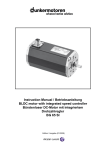
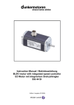
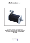
Instruction Manual / Betriebsanleitung
Motor with integrated speed controller
Motor mit integriertem Drehzahlregler
GR 53 SI / GR 63 SI
Edition / Ausgabe (02/2008)
1 Contents
1 Inhalt
Page
Seite
1 Contents
2
1 Inhalt
2
2 About this document
4
2 Über dieses Dokument
4
3 General description
5
3 Allgemeine Beschreibung
5
4 Safety instructions
7
4 Sicherheitshinweise
7
5 Technical data
8
5 Technische Daten
8
3.1 Motor series GR 53 SI / 63 SI
3.2 Proper use
3.3 Standards and guidelines
5.1 Electrical data
5.2 Mechanical data
5.3 Dimensions
5.4 Motor GR 53 SI
5.5 Motor GR 63 SI
5.6 Accessories
5
6
6
8
8
9
9
9
10
6 Installation / terminal assignment
6.1 Mechanical assembly
6.2 Electromechanical compatibility
6.3 Ground wire
6.4 Regeneration
6.5 Connection alternatives
6.6 Motor power supply
and signal interface supply
10
10
11
11
11
12
12
3.1 Motorbaureihe GR 53 SI / 63 SI
3.2 Bestimmungsgemäße Verwendung
3.3 Normen und Richtlinien
5.1 Elektrische Daten
5.2 Mechanische Daten
5.3 Motormasszeichnung
5.4 Motor GR 53 SI
5.5 Motor GR 63 SI
5.6 Optionale Anbauten
5
6
6
8
8
9
9
9
10
6 Installation und Anschlussbelegung 10
6.1 Mechanische Montage
6.2 Elektromagnetische Verträglichkeit
6.3 Schutzleiter Anschluss
6.4 Energierückspeisung
6.5 Anschlussmöglichkeiten
6.6 Spannungsversorgung Motor
und Schnittstellenversorgung
10
11
11
11
12
12
6.6.1 Connection via 12-pole connector at 12V/24V version
13
6.6.2 Connection via 12-pin connector at 40V version
14
6.6.1 Anschluss über 12-pol. Stecker bei 12V-/24V-Ausführung
13
6.6.2 Anschluss über 12-pol. Stecker bei 40 V-Ausführung 14
7 Connection schematic
7 Anschlussschema
6.7 Schematic circuit of the digital outputs 15
6.8 Schematic circuit of the digital inputs 15
7.1 Connection motor power supply
and signal interface supply
7.1.1 Connection 12 V- / 24 V-motors
7.1.2 Connection 40 V-motors
8 Operation hints
8.1 Operation
8.2 Function of the digital inputs IN1
and IN2
8.3 Function of the digital inputs IN3
and IN4
8.4 Teaching of fixed speeds
8.5 Teaching of ramps
8.6 Function of the pulse output OUT1
18
19
19
19
20
20
21
21
22
23
25
6.7 Prinzipschaltung der Digitalausgänge 15
6.8 Prinzipschaltung der Digitaleingänge 15
7.1 Anschluss Leistungsversorgung Motor und Schnittstellenversorgung
7.1.1 Anschluss 12 V- / 24 V-Motoren
7.1.2 Anschluss 40 V-Motoren
8 Betriebshinweise
18
19
19
19
19
20
8.1 Inbetriebnahme
20
8.2 Funktion der Digitaleingänge IN1
und IN2
21
8.3 Funktion der Digitaleingänge IN3
und IN4
21
8.4 Teachen von festen Geschwindigkeiten22
8.5 Teachen von Rampen
23
8.6 Funktion des Pulsausgangs OUT1
25
Instruction Manual/Betriebsanleitung GR 53 SI / GR 63 SI, Version: 1.2 en_de
© 2008 Alcatel-Lucent; Dunkermotoren; D-79848 Bonndorf; Germany
1 Contents
1 Inhalt
8.7 Protection function and fault output OUT3
26
8.8 Function of the analogue input AI+/AI-
27
9 Maintenance & Service
9.1 Motor operation in Q mode
9.2 Maintenance, taking out of service
and disposal
9.3 Service & Support
9.4 Scope of delivery and accessories
9.5 Download PDF-Data
10 Appendix
A) CE-declaration of the manufacturer
28
28
28
29
29
29
30
8.7 Schutzfunktionen und Meldeausgang OUT3
26
8.8 Funktion des Analogeinganges
AI+/AI-
27
9 Wartung & Service
9.1 Motorbetrieb im Q-Modus
9.2 Wartung, Ausserbetriebsetzung
und Entsorgung
9.3 Service & Support
9.4 Lieferumfang und Zubehör
9.5 Download PDF-Daten
10 Anhang
A) CE-Herstellererklärung
Instruction Manual/Betriebsanleitung GR 53 SI / GR 63 SI, Version: 1.2 en_de
© 2008 Alcatel-Lucent; Dunkermotoren; D-79848 Bonndorf; Germany
28
28
28
29
29
29
30
30
2 About this document
2 Über dieses Dokument
2 About this document
2 Über dieses Dokument
These operating instructions introduce you to the
SI drives and provide you with information on all the
stages required for the installation of the drives and the
performance of functional tests.
Notes:
Notes explain the advantages of certain settings and
help you to benefit from the ideal profit of the appliance.
Die vorliegende Betriebsanleitung stellt Ihnen die SIAntriebe vor und informiert Sie über alle Schritte zur
Installation der Antriebe und zur Durchführung von
Funktionstests.
Hinweise:
Hinweise erläutern Vorteile bestimmter Einstellungen
und helfen Ihnen, den optimalen Nutzen aus dem Gerät zu ziehen.
Warning!
Read these
instructions carefully
and follow them!
Warnings are there to protect you from danger, and to
help you to avoid damage to the device.
Warning!
Danger of
electrocution!
When you see this sign, always check that the unit is
disconnected from the electrical power supply, and
take precautions to prevent unintentional switching
on.
Warnhinweise:
Lesen und befolgen
Sie diese sorgfältig!
Warnhinweise sollen Sie vor Gefahr schützen oder
helfen Ihnen, eine Beschädigung des Gerätes zu vermeiden.
Achtung:
Lebensgefahr durch
Stromschlag!
Wenn Sie dieses Zeichen sehen, dann prüfen Sie
stets ob das Gerät spannungsfrei und gegen versehentliches Einschaflten gesichert ist.
Instruction Manual/Betriebsanleitung GR 53 SI / GR 63 SI, Version: 1.2 en_de
© 2008 Alcatel-Lucent; Dunkermotoren; D-79848 Bonndorf; Germany
3 General description
3 Allgemeine Beschreibung
3 General description
3 Allgemeine Beschreibung
3.1 Motor series GR 53/63 SI
3.1 Motorbaureihe GR 53/63 SI
The motor type GR 53 SI / 63 SI represents DC-motors
(brushed DC motor) with an attached speed control
electronic for 4-quadrant operation.
The desired speed is set via an analogue signal input
0 ... +10 V. The four operating modes “clockwise rotation”, “counter clockwise rotation”, “Off” (rapid breakpoint with freewheel) and “Stop” (rapid breakpoint with
holding torque) are controlled via the two digital inputs
IN1 and IN2. Optional, two further digital inputs for additional functions are available. Therewith, among other
things, 2 fixed motor speeds (e.g. for rapid movement
and creep speed), acceleration ramp and braking ramp
can be memorized (Teach). Two digital output signals
are available additionally: one giving 16 pulses per turn
(e.g. for position and speed control), the other showing
“fault”. In case of larger needs, customer specific solutions with special firmware are available on request.
Bei der Motorbaureihe GR 53 SI / 63 SI handelt es sich
um DC-Motoren (bürstenbehaftete Kollektormotoren)
mit angebauter Drehzahlregelelektronik für den
4-Quadrantenbetrieb.
Die
Drehzahlsollwertvorgabe
erfolgt
standardmäßig über einen Analogspannungseingang 0 ... +10 V.
Über zwei digitale Eingänge (IN1, IN2) lassen sich die
vier Betriebszustände „Rechtslauf“, „Linkslauf“, „Aus“
(Schnellstopp mit Freilauf) und „Stopp“ (Schnellstopp
mit Haltemoment) ansteuern. Wahlweise stehen zwei
weitere digitale Eingänge für erweiterte Funktionalität
zur Verfügung. Damit lassen sich unter anderem 2 feste Motordrehzahlen (z.B. für Eil- und Schleichgang)
und Beschleunigungs- und Bremsrampen (z.B. für
sanftes Beschleunigen und Abbremsen) abspeichern
(teachen). Außerdem werden zwei digitale Ausgänge
herausgeführt, womit ein Pulsausgang mit 16 Impulsen
pro Umdrehung (z.B. für Positions- und Geschwindigkeitsüberwachung) und eine Fehlermeldung zur Verfügung stehen. Kundenspezifische Ausführungen mit
spezieller Firmware sind bei größeren Bedarfsfällen
auf Anfrage möglich.
Die Motoren GR 53 SI / 63 SI können auch mit Planeten- oder Schneckengetrieben kombiniert werden,
die in einer Vielzahl fein abgestimter Untersetzungen
verfügbar sind.
The motors GR 53 SI / 63 SI can be combined with
planetary or worm gears with a multitude of fine tuned
gear ratios.
Instruction Manual/Betriebsanleitung GR 53 SI / GR 63 SI, Version: 1.2 en_de
© 2008 Alcatel-Lucent; Dunkermotoren; D-79848 Bonndorf; Germany
3 General description
3 Allgemeine Beschreibung
3.2 Proper use
3.2 Bestimmungsgemäße Verwendung
- The GR 53 SI / 63 SI motor is a supplied part and may be installed into (industrial) machinery and equipment in the described configuration.
- The drive must be securely fixed, and may only be installed using cables and components specified by Dunkermotoren.
- The drive may only be put into operation once the entire system has been installed in accordance with EMC.
- Die Motoren GR 53 SI / 63 SI sind Zulieferteile und dürfen in der beschriebenen Konfiguration in Ma
schinen und Anlagen eingesetzt werden
(industrieller Bereich).
- Der Antrieb muss fest montiert werden und darf nur mit den von Dunkermotoren spezifizierten Kabeln und Zubehörteilen eingesetzt werden.
- Der Antrieb darf erst nach EMV-gerechter Montage des Gesamtsystems in Betrieb genommen werden.
3.3 Standards and guidelines
3.3 Normen und Richtlinien
EU guidelines: the EU guidelines formulate the minimum requirements made on a product and must be observed by all manufacturers and dealers marketing the
product in the member states of the European Union.
EG-Richtlinien: Die EG-Richtlinien formulieren die
Mindestanforderungen an ein Produkt und müssen von
allen Herstellern und Händlern beachtet werden, die
das Produkt in den Mitgliedstaaten der Europäischen
Union auf den Markt bringen.
Machine guideline: the drive is a machine in the sense of
the EU guideline for machinery. It has moveable parts
in accordance with its intended purpose: however, it
may only be installed as a component of a machine or
a system. The advice described in these instructions
regarding installation and operation must be adhered
to.
Maschinenrichtlinie: Der Antrieb ist eine Maschine im
Sinne der EG-Richtlinie für Maschinen. Er hat zweckgerichtet bewegliche Teile, darf aber nur als Bestandteil einer Maschine oder Anlage eingesetzt werden. Die
in dieser Betriebsanleitung beschriebenen Hinweise
zur Installation und Inbetriebnahme müssen beachtet
werden.
EMC guideline: the EU guidelines for EMC apply to
devices which can cause electromagnetic interruptions
or whose operation can be impaired by these interruptions. Compliance of the drive with the EMC guideline
can only be tested once it has been installed. The information pertaining to EMC described in these instructions must be adhered to.
EMV-Richtlinie: Die EG-Richtlinien für EMV gelten für
Geräte, die elektromagnetische Störungen verursachen können oder deren Betrieb durch diese Störungen
beeinträchtigt werden kann. Die Übereinstimmung des
Antriebs mit der EMV-Richtlinie kann erst nach dem
Einbau überprüft werden. Die in dieser Betriebs-anleitung beschriebenen Angaben zur EMV müssen beachtet werden.
Conformity: by means of the conformity declaration of
the product (see appendix), Dunkermotoren confirms
that the drive complies with the safety standards listed
therein and with EMC standards. The product may be
sold and used within the European Union.
Konformität: Mit der Konformitätserklärung (siehe Anhang) des Produkts bescheinigt Dunkermotoren, dass
der Antrieb den dort aufgeführten Normen zur Sicherheit und EMV entspricht. Das Produkt darf in der Europäischen Union vertrieben und eingesetzt werden.
Instruction Manual/Betriebsanleitung GR 53 SI / GR 63 SI, Version: 1.2 en_de
© 2008 Alcatel-Lucent; Dunkermotoren; D-79848 Bonndorf; Germany
4 Safety instructions
4 Sicherheitshinweise
4 Safety instructions
4 Sicherheitshinweise
Warning!
Achtung:
Before commissioning,
the following safety instructions must, without
fail, be read, understood
and observed! Failure to
follow them can result in
danger to persons or damage to the machine.
Failure-free operation requires transport and storage
according to the appropriate requirements. The drives
are to be stored protected against dust, dirt and humidity. It is essential, that the storage conditions are
not beyond the allowed storage temperature resp. air
humidity (see “Technical data”).
The transport must be knock-protected in compliance
with the storage conditions.
The instruction for installing and adjustment of the
drives must be considered.
To enable failure-free operation, a mounting place
should be selected, which environmental conditions
are not beyond the allowed values. The exact values
can be taken from the product description (see “Technical data”).
Mounting or demounting may only take place
under voltage-free condition.
The modules may only be implemented and equipped
by qualified staff according to appropriate standards.
A person can be classified as qualified,
• if he is able to identify and avoid possible dangers as a result of experience,
• if he knows the accident prevention regulations for the used devices
and
• if he is permitted to start up and install the electric circuit and devices according to the standards.
The equipment may only be started up by qualified or
adequate indoctrinated persons.
The local standards at the application area of the devices must be considered.
The safety instructions of the operating devices and
machines must be considered.
To avoid danger, a fully functional EMERGENCYSTOP-button must be placed in direct scope with unhindered access.
Vor der Inbetriebnahme sind unbedingt die
nachfolgen Sicherheitshinweise zu lesen und
zu beachten! Eine Nichtbeachtung kann zu Gefahren bei Personen
oder Beschädigungen
an der Maschine führen!
Der störungsfreie Betrieb setzt den Transport und die
Lagerung nach den entsprechenden Vorgaben voraus.
Die Antriebe sind geschützt vor Staub, Schmutz und
Feuchtigkeit zu lagern. Es ist zu beachten, dass die Lagerungsbedingungen nicht außerhalb der zulässigen
Lagerungstemperatur bzw. Luftfeuchtigkeit liegt (siehe
„Technische Daten“).
Der Transport muss stossgeschützt unter Einhaltung
der Lagerungsbedingungen erfolgen.
Die Anleitung für den Aufbau und die Einrichtung
der Antriebe ist zu beachten.
Um einen störungsfreien Betrieb zu ermöglichen, ist
ein Montage-Ort zu wählen, der keine Umweltbedingungen aufweist, die außerhalb der zulässigen Werte
liegen. Die genauen Werte sind der Produktbeschreibung zu entnehmen (siehe „Technische Daten“).
Die Montage oder Demontage darf nur im spannungslosen Zustand erfolgen.
Die Module dürfen nur von qualifiziertem Personal
nach den entsprechenden Normen eingebaut und eingerichtet werden. Als qualifiziert gilt eine Person dann,
• wenn sie aufgrund ihrer Erfahrung mögliche Gefah-
ren erkennen und vermeiden kann,
• wenn ihr die Unfallverhütungsvorschriften für die eingesetzten Geräte bekannt sind
und
• wenn sie gemäß den Normen Stromkreise und Ge-
räte in Betrieb setzen und installieren darf.
Die Anlage darf nur durch qualifiziertes oder entsprechend geschultes Personal in Betrieb genommen werden.
Die regionalen Normen im Einsatzgebiet der Antriebe
sind zu beachten.
Die Sicherheitshinweise der zu steuernden Geräte und
Maschinen sind zu beachten.
Um Gefahren abwenden zu können, muss ein funktionstüchtiger NOT-AUS-Schalter in direkter Reichweite mit
unbehindertem Zugang liegen.
Instruction Manual/Betriebsanleitung GR 53 SI / GR 63 SI, Version: 1.2 en_de
© 2008 Alcatel-Lucent; Dunkermotoren; D-79848 Bonndorf; Germany
5 Technical data
5 Technische Daten
5 Technical data
5 Technische Daten
5.1 Electrical data
5.1 Elektrische Daten
Rated voltage
12/24V
40V
Maximum motor speed
range
depends on motor
windings and voltage
Speed range adjustable
50 rpm ... rated speed
Minimum motor
voltage
12 V
Maximum motor
voltage
27 V
Maximum ripple on
supply voltage
Max. 5 %
Undervoltage shutdown
10 V
Demolition boundary by
overvoltage
32 V
Required external fuse
8 AT external
Over-temperature
protection
> 85°C at the
power output stage
Max. peak current
(motor)
15 resp. 25 A
42 V
55 V
5.2 Mechanical data
12/24V
40V
Ungeregelter
Drehzahlbereich
je nach Motor und
Betriebsspannung
Regelbarer Drehzahlbereich
50 U/min ... Nenndrehzahl
Minimal zulässige Motorspannung
12 V
Maximal zulässige Motorspannung
27 V
Zulässige Restwelligkeit
der Versorgungsspannung
Max. 5 %
Unterspannungsabschaltung
10 V
Zerstörungsgrenze durch
Überspannung
32 V
Absicherung
8 AT extern erforderlich
Übertemperaturabschaltung
> 85°C an der
Leistungsendstufe
Max. Spitzenstrom
(Wicklung)
15 bzw. 25 A
42 V
55 V
5.2 Mechanische Daten
Temperature range
motor
-20 °C ... +100 °C
housing temperature
Temperaturbereich
Motor
-20°C…+100°C
Gehäusetemperatur
Recommended environmental temperature range *)
0 °C ... 50 °C
Empfohlener Umgebungstemperaturbereich *)
0°C…50°C
Relative humidity
(not condensing)
Max. 90%
Relative
Luftfeuchtigkeit
Max. 90%
Protection class **)
IP 54
Schutzart **)
IP 54
Connector plug
12-pole ***)
Round connector according DIN 45326, company Binder, series 723
Anschlussstecker
12-polig ***)
Rundstecker nach
DIN 45326, Firma
Binder, Serie 723
*) The motor is specified for an ambient temperature of
20°C. The performance data refer to this ambient temperature.
**) The protective system only refers to the motor / gearbox casing. The shaft is to be sealed by the client. The
drive may only be used in an environment complying
with IP54 if the shaft outlet has been installed such that
it is protected from dust and water.
***) Please see the pin diagram for further information.
Nennspannung
*) Der Motor ist für eine Umgebungstemperatur von 20°C
spezifiziert. Die Leistungsangaben beziehen sich auf diese Umgebungstemperatur.
**) Die angegebene Schutzart bezieht sich nur auf das
Motor- bzw. Getriebegehäuse. Die Abdichtung der Welle
ist vom Kunden vorzunehmen. Nur wenn der Wellenaustritt staub- und wassergeschützt montiert wird, kann der
Antrieb in einer Umgebung entsprechend IP54 eingesetzt
werden.
***) Weitere Informationen finden Sie im Abschnitt Anschlussbelegung.
Instruction Manual/Betriebsanleitung GR 53 SI / GR 63 SI, Version: 1.2 en_de
© 2008 Alcatel-Lucent; Dunkermotoren; D-79848 Bonndorf; Germany
5 Technical data
5 Technische Daten
5.3 Dimensions
5.3 Motormasszeichnung
5.4 Motor GR 53 SI
Data / Leistungsdaten
Rated voltage / Nennspannung
Continuous rated speed/ Nenndrehzahl
Continuous rated torque/
Nenndrehmoment
Continuous current / Nennstrom
Starting torque / Anlaufmoment
Starting current / Anlaufstrom
Peak current /
Zulässiger Spitzenstrom der Elektronik
Rotor inertia/ Trägheitsmoment
Weight of motor/ Motorgewicht
Voltage range/
Max. zulässiger Spannungsbereich
Recommended speed control range/
Empfohlener Drehzahlregelbereich
5.4 Motor GR 53 SI
GR 53x30 SI
24 VDC
12 VDC
24 VDC
40 VDC
rpm*)
3790
3600
3000
3000
3000
Ncm*)
9
10
15.5
17
17
A*)
4.5
2.3
5.5
2.9
1.9
Ncm**)
57
67
114***)
143***)
139
A**)
23.7
13.5
35.3***)
22.8***)
14.4
A**)
25
15
25
15
15
gcm2
230
230
460
460
460
g
1050
1050
1360
1360
1360
VDC
12 ... 40
12 ... 40
12 ... 40
12 ... 40
12 ... 40
rpm
50 ... 4096
50 ... 4096
50 ... 4096
50 ... 4096
50 ... 4096
5.5 Motor GR 63 SI
5.5 Motor GR 63 SI
Data / Leistungsdaten
Rated voltage / Nennspannung
Continuous rated speed/ Nenndrehzahl
Continuous rated torque/
Nenndrehmoment
Continuous current / Nennstrom
Starting torque / Anlaufmoment
Starting current / Anlaufstrom
Peak current /
Zulässiger Spitzenstrom der Elektronik
Rotor inertia/ Trägheitsmoment
Weight of motor/ Motorgewicht
Voltage range/
Max. zulässiger Spannungsbereich
Recommended speed control range/
Empfohlener Drehzahlregelbereich
GR 53x58 SI
12 VDC
GR 63x25 SI
GR 63x55 SI
12 VDC
24 VDC
40 VDC
12 VDC
24 VDC
40 VDC
rpm*)
3100
3300
3500
3000
3350
3450
Ncm*)
13.7
14
13.3
24
27
27
A*)
5.2
2.7
1.7
8.7
4.9
3
Ncm**)
82
108***)
118
202***)
211***)
210***)
A**)
27
18***)
12
64***)
40***)
28.6***)
A**)
25
15
15
25
25
15
gcm
400
400
400
750
750
750
g
1400
1400
1400
1900
1900
1900
VDC
12 ... 40
12 ... 40
12 ... 40
12 ... 40
12 ... 40
12 ... 40
rpm
50 ... 4096
50 ... 4096
50 ... 4096
8
50 ... 4096
50 ... 4096
50 ... 4096
2
*)
=100 K; **) Temp = 20°C
***) Will be restricted by peak current of the electronic
*)
=100 K; **) Temp = 20°C
***) Wird durch den Spitzenstrom der Elektronik eingegrenzt
Instruction Manual/Betriebsanleitung GR 53 SI / GR 63 SI, Version: 1.2 en_de
© 2008 Alcatel-Lucent; Dunkermotoren; D-79848 Bonndorf; Germany
6 Installation / terminal assignment
6 Installation und Anschlussbelegung
5.6 Accessories
5.6 Optionale Anbauten
Worm gear (WG)
The worm gear is extremely quiet. In many applications, the gear shaft shifted by 90° compared to the
motor shaft is ideal with regard to structural aspects.
Worm gears with hollow shafts are also available upon
request.
Schneckengetriebe (SG)
Die Schneckengetriebe zeichnen sich durch hohe
Laufruhe aus. Bei vielen Anwendungen ist die um 90°
gegenüber der Motorwelle versetzte Getriebewelle von
baulichen Gegebenheiten her optimal. Auf Anfrage sind
Schneckengetriebe auch mit Hohlwelle lieferbar.
Gear reductions
5:1 … 80:1
Untersetzungen
5:1 … 80:1
Constant torques
max. 1500 Ncm
Dauerdrehmomente
max. 1500 Ncm
Planetary gear (PLG)
Planetary gears have the most reliable constant torques
of all gears and are very compact, have a low weight
and an excellent degree of effectiveness.
Planetengetriebe (PLG)
Planetengetriebe haben die höchsten zulässigen Dauerdrehmomente aller Getriebe bei gleichzeitig sehr
kompakter Bauform, geringem Gewicht und ausgezeichnetem Wirkungsgrad.
Gear reductions
3:1 … 512:1
Untersetzungen
3:1 … 512:1
Constant torques
max. 6000 Ncm
Dauerdrehmomente
max. 6000 Ncm
Breaks (E)
Breads are available on request.
Bremsen (E)
Bremsen sind auf Anfrage erhätlich
6 Installation / terminal assignment
6 Installation und Anschlussbelegung
Please note:
The safety notes in section 4
must be read and complied
with before in-stallation! Ensure
that the device is voltage free!
6.1 Mechanical assembly
6.1 Mechanische Montage
Cautionary note:
Ensure that the pins are not
damaged during installation.
Bent pins can destroy the
drive by causing a short circuit.
Check the drive for visible damage before carrying out
the installation. Do NOT install damaged drives.
The drive must be fastened to a flat surface using 4
screw connections. The flange screws must be prevented from distortion by means of spring washers.
The motor drive shaft may be axially or radially loaded with a maximum of 130/ 90 N. For gear motors,
please refer to the relevant documentation regarding the
gears.
10
Achtung:
Vor der Installation sind unbedingt die Sicherheitshinweise
in Abschnitt 4 zu lesen und zu
beachten! Gerät spannungsfrei schalten!
Vorsicht:
Achten Sie bei der Installation
darauf, dass die Steckverbinder nicht beschädigt werden.
Umgebogene Pins können
den Antrieb durch Kurzschluss
zerstören.
Prüfen Sie den Antrieb vor der Installation auf äußerlich
sichtbare Beschädigungen. Bauen Sie beschädigte Antriebe nicht ein.
Der Antrieb muss mit 4 Schraubverbindungen an einer
planen Oberfläche befestigt werden. Die Flanschschrauben müssen mit Federscheiben gegen Verdrehen geschützt werden.
Die Motorabtriebswelle darf mit maximal 90 bzw. 130 N
radial oder axial belastet werden. Bei Getriebmotoren
sind die entsprechenden Daten der Dokumentation zum
Getriebe zu entnehmen.
Instruction Manual/Betriebsanleitung GR 53 SI / GR 63 SI, Version: 1.2 en_de
© 2008 Alcatel-Lucent; Dunkermotoren; D-79848 Bonndorf; Germany
6 Installation / terminal assignment
6 Installation und Anschlussbelegung
6.2 Electromechanical compatibility
6.2 Elektromagnetische Verträglichkeit
Electromagnetic radiated interferences occur in the
drive GR 53 SI / 63 SI and the machine in which the
drive is installed. Should no suitable protective measures beimplemented, these interferences can influence the signals of control panel wirings and can endanger the system‘s operational safety.
The electromagnetic compatibility of the machine must
be tested and ensured before it is put into operation.
Beim Antrieb GR 53 SI / 63 SI und bei der Maschine,
in welche der Antrieb eingebaut wird, entstehen elektromagnetische Störstrahlungen. Diese können ohne
geeignete Schutzmaßnahmen die Signale von Steuerleitungen und Anlageteilen beeinflussen und die Betriebssicherheit der Anlage gefährden.
Vor dem Betrieb muss die elektromagnetische Verträglichkeit der Maschine geprüft und sichergestellt
werden.
6.3 Ground wire
6.3 Schutzleiter Anschluss
The motor housing must be
earthed to protect the drive
against damage or destruction
due to static discharge (ESD)
Zum Schutz des Antriebs vor
Beschädigung oder Zerstörung durch statische Entladung (ESD) muss das Motorgehäuse geerdet werden.
• The motor housing must be connected to the machine
earth via a separate earth wire
• Please do not touch the connector pins
• If possible, the drives should only be handled by persons wearing protective ESD equipment
• Das Motorgehäuse muss mit einer separaten Erdlei-
tung mit der Maschinenmasse verbunden werden.
• Bitte die Steckerpins nicht berühren.
• Nach Möglichkeit sollten die Antriebe nur von Perso-
nen mit ESD-Schutzausrüstung angefasst werden.
6.4 Regeneration
6.4 Energierückspeisung
Upon braking, the kinetic energy is returned to the intermediate circuit of the closed loop control circuit as electric energy. This can result in increased voltages in the closed loop
control circuit which, in extreme cases, can cause damage
to electrical components. For protection the supply must
absorb the regeneration energy. DC mains adapters with a
bridge recitifer and a filter capacitor of at least 1,000µF per
1A of motor nominal current should be used. The use of a
discharging resistor (e.g. 1kOhm, loss capacity of U2/1,000
ohm) is recommended. The motors have an integrated
ballast circuit which, in the event of increased voltages of
>53V, short-circuits the input voltage via a ballast resistor
with 2.2 ohm. This ballast resistor has been designed for a
maximum braking capacity of 20 watt.
Bei Bremsvorgängen wird die kinetische Energie als elektrische Energie in den Zwischenkreis des Regelkreises
zurückgeführt. Dabei kann es im Zwischenkreis zu Spannungsüberhöhungen kommen, die im Extremfall Schäden
an elektrischen Bauteilen verursachen können. Als Schutzmaßnahme muss die Versorung generell die rückgespeiste Bremsenergie aufnehmen. Es sollten DC-Netzteile mit
Brückengleichrichter und ein Glättungskondesator von
mindestens 1000µF pro 1A Motornennstrom verwendet
werden. Zusätzlich wird die Verwendung eines Entladewiderstands (z.B. 1kOhm, Verlustleistung >U2/1000Ohm)
empfohlen.
Please note:
In the event of frequent hard
braking, the ballast resistor
and, consequently also further
circuit components, can be
overloaded and destroyed unless suitable measures are taken to avoid the occurrence of
excessive increased voltages
(see above: filter capacitor).
Instruction Manual/Betriebsanleitung GR 53 SI / GR 63 SI, Version: 1.2 en_de
© 2008 Alcatel-Lucent; Dunkermotoren; D-79848 Bonndorf; Germany
Achtung:
Bei häufigem starken Bremsen kann der Ballastwiderstand und als Folge auch weitere Schaltungsteile überlastet
und zerstört werden, falls nicht
geeignete Maßnahmen zur
Vermeidung von zu starken
Spannungsüberhöhungen
(s.o. Glättungskondensator)
ergriffen werden.
11
6 Installation / terminal assignment
6 Installation und Anschlussbelegung
6.5 Connection alternatives
6.5 Anschlussmöglichkeiten
In the following, the standard connection types with 12pole connectors are described again explicitly.
The alternative with 12-pole connector offers the greatest functional range including teaching of 2 fixed
speeds as well as run-up ramp and break ramp, and
should be used in favour.
Further alternatives with 8-pole connector and 8 lead
respectively are not available in the standard program
but can be delivered in case of a major inquiry.
Im folgenden werden die Standardanschlussarten mit
12-pol. Stecker nochmals explizit dargestellt.
Die Variante mit 12-pol. Stecker bietet den größten
Funktionsumfang einschließlich dem Abspeichern
(engl. „Teachen“) von 2 festen Geschwindigkeiten sowie von Hochlauf- und Bremsrampe und sollte deshalb
bevorzugt eingesetzt werden.
Weitere Varianten mit 8-pol. Stecker bzw. 8 Litzen sind
nicht im Standardprogramm verfügbar, können aber bei
größeren Bedarfsfällen auf Anfrage geliefert werden.
6.6 Motor power supply and signal
interface supply
6.6 Spannungsversorgung Motor und Schnittstellenversorgung
Plug:
Round plug to DIN 45326, Binder, Series 723
The 12-pin drive connector serves for the motor power
supply and the electronic supply.
Stecker:
Rundstecker nach DIN 45326, Fa. Binder, Series 723
Der 12-polige Antriebsstecker dient zur Leistungsversorgung des Antriebs und zur Elektronikversorgung.
E
F
G
M
D
H
C
L
J
B
12
A
K
Instruction Manual/Betriebsanleitung GR 53 SI / GR 63 SI, Version: 1.2 en_de
© 2008 Alcatel-Lucent; Dunkermotoren; D-79848 Bonndorf; Germany
6 Installation / terminal assignment
6 Installation und Anschlussbelegung
6.6.1 Connection via 12-pole connector at 12V/24V version
6.6.1 Anschluss über 12-pol. Stecker bei 12V-/24V-Ausführung
ConnectorPin
Connection
Function
Strand colour
of the connecting cable with
12-pole angular
connector (*)
SteckerPin
Anschluss
Funktion
Litzenfarbe
der Anschlussleitung mit 12
pol. Winkelstecker (*)
E+F
UE
motor supply
+12V/24V
red (1 mm2)
E+F
UE
Motorversorgung +12V/24V
rot (1 mm2)
D*
IN4
spd1/spd2
(input): “0” =
speed1,
“1” = speed2
green
D*
IN4
spd1/spd2
(Eingang): „0“ =
speed1,
„1“ = speed2
grün
M+G
Gnd
0 V ground for
UE
black
(1 mm2)
M+G
Gnd
0 V Bezugsmasse für UE
schwarz
(1 mm2)
B
IN1
Left
yellow
B
IN1
Links
gelb
C
IN2
Right
blue
C
IN2
Rechts
blau
J
AI+
Analogue set
value N+
(0 ... +10 V)
pink
J
AI+
Analogsollwert
N+
(0 ... +10 V)
rosa
H
AI-
Analogue set
value N- (reference mass for
N+)
magenta
H
AI-
Analogsollwert
N- (Referenzmasse für N+)
violett
A
OUT1
Pulse output,
15 pulses/rot.,
(+24 V-switching)
orange
A
OUT1
Pulsausgang,
15 Pulse/Umdr.,
(+24 V-schaltend)
orange
K
OUT3
/fault-output: “1”
= no fault, “0” =
fault
white
K
OUT3
/fault-Ausgang:
„1“ = keine
Störung, „0“ =
Störung
weiß
L**
IN3
Teach-input
brown
L**
IN3
Teach-Eingang
braun
(*) Lead colours refers to standard connection cables
of Dunkermotoren.
(*) Litzenfarben beziehen sich auf Standard Anschlussleitungen von Dunkermotoren.
**) See chapter 8.3 for further functions.
**) Weitere Funktionen von IN3 und IN4 siehe Punkt 8.3.
Instruction Manual/Betriebsanleitung GR 53 SI / GR 63 SI, Version: 1.2 en_de
© 2008 Alcatel-Lucent; Dunkermotoren; D-79848 Bonndorf; Germany
13
6 Installation / terminal assignment
6 Installation und Anschlussbelegung
6.6.2 Connection via 12-pin connector at 40V version
6.6.2 Anschluss über 12-pol. Stecker bei
40 V-Ausführung
Connector-Pin
Connection
Function
Strand colour of the
connecting
cable with
12-pole
angular connector (*)
SteckerPin
Anschluss
Funktion
Litzenfarbe der
Anschlussleitung mit
12 pol.
Winkelstecker (*)
E+F
UE
motor supply
+ 40V DC
red (1 mm2)
E+F
UE
Motorversorgung
+40V DC
rot (1 mm2)
D
+24V
Logic Supply
green
D
+24V
Logikversorgung
grün
M+G
Gnd
black
(1 mm2)
M+G
Gnd
IN1
Left
yellow
B
IN1
0 V Bezugsmasse für UE
schwarz (1
mm2)
B
0 V ground
for UE
Links
gelb
C
IN2
Right
blue
C
IN2
Rechts
blau
J
AI+
Analogue set
value N+
(0 ... +10 V)
pink
J
AI+
Analogsollwert N+
(0 ... +10 V)
rosa
H
AI-
Analogue set
value N- (reference mass
for N+)
magenta
H
AI-
Analogsollwert violett
N- (Referenzmasse für N+)
A
OUT1
Pulse output, orange
15 pulses/rot.,
(+24 V-switching)
A
OUT1
orange
K
OUT2
Direction of
rotation
hi = left
lo = right
white
Pulsausgang,
15 Pulse/
Umdr.,
(+24 V-schaltend)
K
OUT2
Drehrichtung
hi = links
lo = rechts
weiß
L
OUT3
hi =o.k.
lo = fault
OK-Message
brown
L
OUT3
hi = O.k.
lo = Störung
OK-Meldung
braun
(*) Lead colours refers to standard connection cables
of Dunkermotoren.
(*) Litzenfarben beziehen sich auf Standard Anschlussleitungen von Dunkermotoren.
Note: Pin connection according to 12V/24V version on
request available
Hinweis: Steckerbelegung entsprechend der 12V/24VVariante sind auf Anfrage möglich
14
Instruction Manual/Betriebsanleitung GR 53 SI / GR 63 SI, Version: 1.2 en_de
© 2008 Alcatel-Lucent; Dunkermotoren; D-79848 Bonndorf; Germany
6 Installation / terminal assignment
6 Installation und Anschlussbelegung
6.7 Schematic circuit of the digital outputs
6.7 Prinzipschaltung der Digitalausgänge
Output
Ausgang
Chargeable
with max.
12 mA.
Mit max.
12 mA
belastbar.
6.8 Schematic circuit of the digital inputs
6.8 Prinzipschaltung der Digitaleingänge
Instruction Manual/Betriebsanleitung GR 53 SI / GR 63 SI, Version: 1.2 en_de
© 2008 Alcatel-Lucent; Dunkermotoren; D-79848 Bonndorf; Germany
15
6 Installation / terminal assignment
6 Installation und Anschlussbelegung
Mating connector with cable (please oder in addition):
Adequate connector cables with different standard
lengths are available for the motors GR 53/63 SI with
connector plugs (12-pole). They are shielded and dragchain capable. A cable is ready for connection to the
motor by an angled round connector which is already
fit to one cable end. The cable is cut plain on the other
side. The cable has a diameter of 8.2 mm and is equipped with an outer overall-shielding. It fulfills the DESINAguidelines.
With regards to the power supply of the electronics, the
cable has two wires with a cross section dimension of
1 mm2 each. The signal transmission wires have a
cross section dimension of 0.22 mm2 each. Following
cables are available as standard:
Gegenstecker mit Anschlussleitung (bitte mitbestellen):
Für die Motoren GR 53/63 SI mit Anschlussstecker (12polig) stehen entsprechende geschirmte und schleppkettentaugliche, fertig konfektionierte Anschlussleitungen in verschiedenen Längen ab Lager zur
Verfügung. Die Leitungen sind auf einer Seite mit einer
entsprechenden Winkeldose anschlussfertig konfektioniert. Auf der anderen Seite sind die Leitungen glatt abgeschnitten. Die Leitungen haben einen Durchmesser
von 8,2 mm und sind mit einem äußeren Gesamtschirm
versehen. Sie erfüllen die Richtlinien nach DESINA.
Für die Leistungsversorgung der Elektronik haben die
Leitungen 2 Litzen mit einem Querschnitt von 1 mm2
und für die Signalübertragung weitere Litzen einen
Querschnitt von 0,22 mm2. Es sind folgende Leitungslängen lieferbar:
Length
Länge
1.5 m
1,5 m
3m
3m
6m
6m
10 m
10 m
Standard (Angled position not adjustable)
16
Standard (Winkelposition einstellbar)
Instruction Manual/Betriebsanleitung GR 53 SI / GR 63 SI, Version: 1.2 en_de
© 2008 Alcatel-Lucent; Dunkermotoren; D-79848 Bonndorf; Germany
6 Installation / terminal assignment
6 Installation und Anschlussbelegung
Option (angled position adjustable)
Option (Winkelposition einstellbar)
Instruction Manual/Betriebsanleitung GR 53 SI / GR 63 SI, Version: 1.2 en_de
© 2008 Alcatel-Lucent; Dunkermotoren; D-79848 Bonndorf; Germany
17
7 Connection schematic
7 Anschlussschema
7 Connection schematic
7 Anschlussschema
Warning!
Achtung!
Before commissioning, the safety instructions must, without fail, be read,
understood and then observed!
Vor der Inbetriebnahme sind unbedingt die Sicherheitshinweise zu lesen und zu beachten!
An incorrectly set parameter can,
under some circumstances, result
in oscillation of the controller and
destruction of the motor. It is recommended that current limits and control parameters are initially set to low
values and then carefully increased
in small steps.
Ein falsch eingestellter Parameter
kann unter Umständen zum Schwingen des Reglers führen und den
Motor zerstören. Es empfiehlt sich,
Stromgrenzen und Reglerparameter,
von kleinen Werten beginnend vorsichtig zu erhöhen.
Beim Anschluss der Antriebe ist unbedingt die richtige Polarität sowohl
der Spannungsversorgungen für
Motor und Buselektronik sowie der
Datenleitungen zu prüfen. Ein verpolen der Spannungsversorgung des
Motors kann die Leistungselektronik
zerstören! Der Antrieb enthält keinen
Verpolungsschutz für die Motorspannung.
It is absolutely important for connecting the cables to check the right
polarity of the power supply to the
motor, bus electronic and the data
line. A wrong connection of the power supply maybe destroy the power
electronic. The motor isn‘t protected
against wrong connection of the power supply.
Failure to follow them can result in danger to persons
or damage to the machine.
Eine Nichtbeachtung kann zu Gefahren an Personen
oder Beschädigungen an der Maschine.
18
Instruction Manual/Betriebsanleitung GR 53 SI / GR 63 SI, Version: 1.2 en_de
© 2008 Alcatel-Lucent; Dunkermotoren; D-79848 Bonndorf; Germany
7 Connection schematic
7 Anschlussschema
7.1 Connection motor power supply and
signal interface supply
7.1 Anschluss Leistungsversorgung
Motor und Schnittstellenversorgung
7.1.1 Connection 12 V- / 24 V-motors
7.1.1 Anschluss 12 V- / 24 V-Motoren
Signals (E/A):
OUT 3
IN 3
L
7.1.2 Connection 40 V-motors
red/rot
Logic
M
+42 V DC
GND (0V)
Instruction Manual/Betriebsanleitung GR 53 SI / GR 63 SI, Version: 1.2 en_de
© 2008 Alcatel-Lucent; Dunkermotoren; D-79848 Bonndorf; Germany
D
+40 V DC
GND (0V)
green/grün
G
black/schwarz
F
black/schwarz
E
red/rot
OUT 3
L
Power
red/rot
OUT 2
K
brown
braun
AI+
J
white/weiß
AIH
pink/rosa
IN 2
C
violet/violett
IN 1
B
blue/blau
OUT 1
Supply:
A
yellow/gelb
M
+12V DC / 24 V DC
GND (0V)
7.1.2 Anschluss 40 V-Motoren
Signals (E/A):
orange/Orange
F
G
red/rot
pink/rosa
violet/violett
E
black/schwarz
AI+
K
black/schwarz
AI-
J
brown
braun
IN 4
H
white/weiß
IN 2
D
green/grün
IN 1
C
blue/blau
B
yellow/gelb
A
orange/Orange
OUT 1
Supply:
19
8 Operation hints
8 Betriebshinweise
8 Operation hints
8 Betriebshinweise
8.1 Operation
8.1 Inbetriebnahme
Attention:
Before starting, the following
safety instructions must be read
and observed necessarily.
Non-observance may cause
hazards of persons or damage
machines!
First, connect the supply voltage to the motor. Thereby
pay attention to the correct polarity and height of the
supply voltage. After this, connect the control inputs
(IN1, IN2 and, if necessary, the set value voltage for
the motor speed).
Note:
The motor may not be switched on/off via the supply
voltage (as long as IN1 and IN2 are on a fixed voltage
level), because an undervoltage detection could happen
under certain circumstances. If the motor is switched
on a short time afterwards, the processor makes no
„reset“, because he still works with residual voltage. If
the fault is not reset properly via “OFF” (IN1 = IN2 = 0),
the motor start can fail sporadically. For reset (confirmation), the motor must be transferred into status “OFF”
(IN1 = IN2 = 0) at activated supply voltage.
20
Achtung:
Vor der Inbetriebnahme sind unbedingt die Sicherheitshinweise
zu lesen und zu beachten!
Eine Nichtbeachtung kann zu
Gefahren bei Personen oder
Beschädigungen an der Maschine führen!
Zuerst die Versorgungsspannung an den Motor anschließen. Dabei auf richtige Polarität und Höhe der
Versorgungsspannung achten. Erst danach die Steuereingänge (IN1, IN2 und ggf. die Sollwertspannung zur
Drehzahlvorgabe) beschalten.
Hinweis:
Der Motor soll nicht über die Versorgungsspannung
ein-/ausgeschaltet werden (solange IN1, IN2 auf
festem Spannungspegel liegen), da es beim Ausschalten unter bestimmten Bedingungen zu einer Unterspannungserkennung kommen kann. Wird der Motor
kurz darauf wieder eingeschaltet, macht der Prozessor
kein „reset“, da er noch mit einer Restspannung arbeitet. Wenn der Fehler nicht durch „AUS“ (IN1 = IN2 = 0)
sauber zurückgesetzt wird, kann der Motor sporadisch
nicht einschalten. Zum Rücksetzen (Quittierung) muss
der Motor bei eingeschalteter Versorgungsspannung in
den Zustand „AUS“ (IN1 = IN2 = 0) versetzt werden.
Instruction Manual/Betriebsanleitung GR 53 SI / GR 63 SI, Version: 1.2 en_de
© 2008 Alcatel-Lucent; Dunkermotoren; D-79848 Bonndorf; Germany
8 Operation hints
8 Betriebshinweise
8.2 Function of the digital inputs IN1 and IN2
8.2 Funktion der Digitaleingänge IN1 und IN2
With the help of the two digital inputs IN1 and IN2, altogether 4 operating conditions can be triggered, because
of the fact that to each of the both inputs the logical
states 0 and 1 are dedicated:
Mit Hilfe der beiden digitalen Eingänge IN1 und IN2
lassen sich insgesamt 4 Betriebszustände ansteuern,
da jedem der beiden Eingänge die logischen Zustände
0 und 1 zugeordnet sind:
0 complies with an input level of 0 ... 6 V
1 complies with an input level of 7 ... 24 V
0 entspricht einem Eingangspegel von 0 ... 6 V
1 entspricht einem Eingangspegel von 7 ... 24 V
The following operating conditions can be triggered:
Die folgenden Betriebszustände können angesteuert
werden:
IN1
IN2
Function
IN1
IN2
Funktion
0
0
Controlling not active, output stage not
provided with current, no holding torque
0
0
Reglersperre, Endstufe nicht
bestromt, kein Haltemoment
1
0
Counter clockwise rotation (motor
shaft turns counter clockwise)
1
0
Linkslauf (Motorwelle dreht gegen
den Uhrzeigersinn)
0
1
Clockwise rotation (motor shaft
turns clockwise)
0
1
Rechtslauf (Motorwelle dreht im
Uhrzeigersinn)
1
1
Stop with holding torque
1
1
Stopp mit Haltemoment
8.3 Function of the digital inputs IN3 and IN4
8.3 Funktion der Digitaleingänge IN3 und IN4
In case the motor provides the option (inputs IN3, IN4
lead through), two fixed speed values can be adjusted
by “teaching”.
Falls der Motor die Option bietet (Eingänge IN3, IN4
herausgeführt), können zwei feste Geschwindigkeitswerte eingestellt und abgespeichert (engl. „Teachen“)
werden.
Note:
In the basic setting (delivery status ex works), 2 fixed
speed values spd1 and spd2 are preset:
Hinweis:
In der Grundeinstellung (Auslieferungszustand ab
Werk) sind bereits 2 feste Geschwindigkeitswerte spd1
und spd2 voreingestellt:
spd1 = 200 rpm
spd2 = 2500 rpm
spd1 = 200 rpm
spd2 = 2500 rpm
Furthermore, it can be toggled between motor speed
regulated mode (50 ... rated speed) and unregulated
mode. In unregulated mode, the motor can be operated up to its maximum idle-running speed. With the
help of the two digital inputs IN3 and IN4, altogether 4
operating conditions can be triggered, because of the
fact that to each of the both inputs the logical states 0
and 1 are dedicated:
Darüber hinaus kann zwischen drehzahlgeregeltem
Betrieb (50 ... Nenndrehzahl) und ungeregeltem Betrieb
um-geschaltet werden. Im ungeregelten Betrieb kann
der Motor bis zu seiner maximalen Leerlaufdrehzahl
betrieben werden. Mit Hilfe der beiden digitalen Eingänge IN3 und IN4 lassen sich insgesamt 4 Betriebszustände ansteuern, da jedem der beiden Eingänge
die logischen Zustände 0 und 1 zugeordnet sind:
0 complies with an input level of 0 ... 6 V
1 complies with an input level of 7 ... 24 V
0 entspricht einem Eingangspegel von 0 ... 6 V
1 entspricht einem Eingangspegel von 7 ... 24 V
Instruction Manual/Betriebsanleitung GR 53 SI / GR 63 SI, Version: 1.2 en_de
© 2008 Alcatel-Lucent; Dunkermotoren; D-79848 Bonndorf; Germany
21
8 Operation hints
8 Betriebshinweise
The following operating conditions can be triggered:
Die folgenden Betriebszustände können angesteuert
werden:
IN3
IN4
Function
IN3
IN4
Funktion
0
0
Controlled motor speed mode
(adjustable via analogue input)
0
0
Drehzahlregelbetrieb
(über Analogeingang einstellbar)
0
1
Uncontrolled operation (adjustable
via analogue input)
0
1
Ungeregelter Betrieb
(über Analogeingang einstellbar)
1
0
Fix adjusted, controlled motor speed
spd1 = 200 rpm
1
0
Festdrehzahl
spd1
1
1
Fix adjusted, controlled motor speed
spd2 = 2500 rpm
1
1
Festdrehzahl
spd2
8.4 Teaching of fixed speeds
8.4 Teachen von festen Geschwindigkeiten
Teaching of a desired fixed speed takes place as follows:
Das Teachen (Einstellen und Abspeichern) einer gewünschten festen Geschwindigkeit erfolgt folgendermaßen:
1. Adjust speed at analogue input, the motor must keep it constantly.
1. Geschwindigkeit am Analogeingang einstellen, der Motor muss diese konstant halten.
2. Stop motor (stop with holding torque):
IN1 = 1 and IN2 = 1 (high).
2. Motor stoppen (Stopp mit Haltefunktion):
IN1 = 1 und IN2 = 1 (high).
3. Toggle 5 times with IN3 (switch between high and low). OUT3 shows via rapid signal changing (approx. 2 Hz), that the motor is in Teach-Mode. The motor can be started and stopped arbitrary frequent.
3. Mit IN3 5 mal toggeln (zwischen high und low hin- und herschalten). OUT3 zeigt durch schnellen Signalwechsel (ca. 2 Hz) an, dass sich der Motor im Teach-Modus befindet. Der Motor kann beliebig oft gestartet und gestoppt werden.
4. Select spd1 or spd2 with IN4
(IN4 = 0 => Low-Speed, IN4 = 1 => High-Speed).
Note: This allocation is obligatory, because one braking or acceleration ramp is dedicated to the speeds in each case.
4. Mit IN4 spd1 oder spd2 auswählen
(IN4 = 0 => Low-Speed, IN4 = 1 => High-Speed).
Hinweis: Diese Zuordnung ist zwingend erforder-
lich, da den Geschwindigkeiten jeweils eine Brems- oder Beschleunigungsrampe zugeordnet ist.
5. Toggle IN3 5 times again, OUT3 shows the accep
tance of the value via low signal changing (approx. 1 Hz).
5. IN3 wieder 5 mal toggeln, OUT3 zeigt durch lang
samen Signalwechsel (ca. 1 Hz) die Übernahme des Wertes an.
6. For permanent storage, start the motor again via separating from the supply voltage.
To teach the second fixed speed, repeat this proce
dure.
6. Zur bleibenden Speicherung ist der Motor durch Trennen der Versorgungsspannung neu zu starten.
Zum Teachen der zweiten festen Geschwindigkeit ist der Vorgang zu wiederholen.
22
Instruction Manual/Betriebsanleitung GR 53 SI / GR 63 SI, Version: 1.2 en_de
© 2008 Alcatel-Lucent; Dunkermotoren; D-79848 Bonndorf; Germany
8 Operation hints
8 Betriebshinweise
8.5 Teaching of ramps
8.5 Teachen von Rampen
In case the motor provides the option (inputs IN3, IN4
lead through), the acceleration and braking ramp can
be adjusted by “teaching”.
Falls der Motor die Option bietet (Eingänge IN3, IN4
herausgeführt), können die Beschleunigungs- und
Bremsrampe eingestellt und abgespeichert (engl. „Teachen“) werden.
Note: The adjusted ramps are only active during toggling between the 2 fixed, stored speeds spd1 and spd2,
but not at speed allegation via the analogue input or at
stopping the motor via IN1 and IN2.
Hinweis: Die eingestellten Rampen sind dabei nur beim
Umschalten zwischen den 2 fest abgespeicherten Geschwindigkeiten spd1 und spd2 wirksam, nicht jedoch
bei Geschwindigkeitsvorgabe über den Analogeingang
oder beim Stoppen des Motors mit IN1 und IN2.
Note: In the delivery status ex works, 2 fixed ramp times
for the acceleration ramp Tr (rise time) and the braking
ramp Tf (fall time) are preset:
Hinweis: Im Auslieferungszustand ab Werk sind bereits
2 feste Rampenzeiten für die Beschleunigungsrampe
Tr (rise time) und die Bremsrampe Tf (fall time) voreingestellt:
Tr = 200 ms
Tf = 50 ms
Tr = 200 ms
Tf = 50 ms
With the help of the set value voltage US between the
analogue inputs AI+ and AI-, ramp times between 20 ms
and 20 s can be adjusted referring to 1000 rpm speed
modification. Thereby, the set value voltage US = 0 ...
10 = V is converted proportionally by the processor into
a number z = 0 ... 1024. The following interrelationship
applies for the ramp time T, orientated to a speed modification of 1000 rpm:
Mit Hilfe der Sollwertspannung US zwischen den
Analogeingängen AI+ und AI- können Rampenzeiten
zwischen 20 ms und 20 s bezogen auf 1000 rpm Geschwindigkeitsänderung eingestellt werden. Dabei wird
die Sollwertspannung US = 0 ... 10 V proportional in
eine Zahl z = 0 ... 1024 im Prozessor umgesetzt. Für
die Rampenzeit T bezogen auf eine Geschwindigkeitsänderung um 1000 rpm gilt größenordnungsmäßig folgender Zusammenhang:
T = (20000 / z) ms
T = (20000 / z) ms
When Teaching the ramps, the speed is incremented
(acceleration) or decremented (braking) by a computed
value in a time pattern of 10 ms. The ramp function is
upstream to the speed controller as simple set point
setter. For clarification, some values are presented in
table form:
(see next page)
Die Geschwindigkeit wird beim Rampen in einem Zeitraster von 10 ms um einen errechneten Wert inkrementiert (Beschleunigung) oder dekrementiert (Bremsen).
Die Rampenfunktion ist als einfacher Sollwertsteller
dem Drehzahlregler vorgeschaltet. Zur Verdeutlichung
sind einige Werte tabellarisch dargestellt:
(siehe nächste Seite)
Instruction Manual/Betriebsanleitung GR 53 SI / GR 63 SI, Version: 1.2 en_de
© 2008 Alcatel-Lucent; Dunkermotoren; D-79848 Bonndorf; Germany
23
8 Operation hints
8 Betriebshinweise
US (Volt)
z = 1024 * U /10 T (ms) per
(number)
1000 rpm
US (Volt)
z = 1024 * U /10 T (ms) pro
(Zahl)
1000 rpm
0,00
0
20000
0,00
0
20000
0,01
1
19531
0,01
1
19531
0,02
2
9766
0,02
2
9766
0,05
5
3906
0,05
5
3906
0,10
10
1953
0,10
10
1953
0,20
20
977
0,20
20
977
0,50
51
391
0,50
51
391
1,00
102
195
1,00
102
195
2,00
205
98
2,00
205
98
5,00
512
39
5,00
512
39
10,00
1024
20
10,00
1024
20
Via speed control using hall signals (without high resolution encoder), achievement of an accurate operating
profile is not possible. Hence, this ramp function must
be considered as soft starting and soft braking.
The motor will require a longer starting time if ramp
times are too long.
Teaching of the ramps takes place as follows:
Durch die Drehzahlregelung mittels Hallsignalen (ohne
hochauflösenden Geber) ist das Erreichen eines exakten Fahrprofils nicht möglich. Deshalb ist diese Rampenfunktion nur als Sanftanlauf und Sanftbremsung zu
verstehen.
Werden die Rampen zu flach parametriert so entsteht
eine größere Motoranlaufzeit.
Das Teachen (Einspeichern) der Rampen erfolgt folgendermaßen:
1. Switch motor to “OFF” (IN1 = 0 and IN2 = 0).
1. Motor auf „AUS“ schalten (IN1 = 0 und IN2 = 0).
2. Toggle 5 times with IN3. OUT3 shows via rapid sig-
nal changing (approx. 2 Hz), that the motor is in Teach-Mode. The motor can be started and
stopped arbitrary frequent.
2. Mit IN3 5 mal toggeln, OUT3 zeigt durch schnellen Signalwechsel (ca. 2 Hz) an, dass sich der Motor im Teach-Modus befindet. Der Motor kann beliebig oft gestartet und gestoppt werden.
3. Adjust the ramp time T with the analogue input (see above). The ramp can be tested by switching IN4.
3. Mit dem Analogeingang die Rampenzeit T (siehe oben) einstellen. Die Rampe kann durch das Um-
schalten an IN4 getestet werden.
4. If the ramp is optimal, the motor can be switched off by IN1 = 0 and IN2 = 0.
4. Ist die Rampe optimal, wird der Motor mit IN1 = 0 und IN2 = 0 ausgeschaltet.
5. IN4 = 0 selects the braking ramp, IN4 = 1 the acce-
leration ramp.
Note: This allocation is obligatory, because one bra king or acceleration ramp is dedicated to the speeds in each case.
5. Mit IN4 = 0 wird die Bremsrampe, mit IN4 = 1 die Beschleunigungsrampe ausgewählt.
Hinweis: Diese Zuordnung ist zwingend erforder-
lich, da den Geschwindigkeiten jeweils eine Brems- oder Beschleunigungsrampe zugeordnet ist.
6. Toggle IN3 5 times again, OUT3 shows the accep-
tance of the value via low signal changing (approx. 1Hz).
6. IN3 wieder 5mal toggeln, OUT3 zeigt durch lang-
samen Signalwechsel (ca. 1 Hz) die Übernahme des Wertes an.
7. For permanent storage, start the motor again via
separating from the supply voltage.
To teach the second ramp, repeat this procedure.
7. Zur bleibenden Speicherung ist der Motor durch Trennen der Versorgungsspannung neu zu starten.
24
Zum Teachen der zweiten Rampe ist der Vorgang zu
wiederholen.
Instruction Manual/Betriebsanleitung GR 53 SI / GR 63 SI, Version: 1.2 en_de
© 2008 Alcatel-Lucent; Dunkermotoren; D-79848 Bonndorf; Germany
8 Operation hints
8 Betriebshinweise
8.6 Function of the pulse output OUT1
8.6 Funktion des Pulsausgangs OUT1
The pulse output OUT1 provides 15 impulses per motor
turn, whereas the pulse duration tP and the pulse brake
t0 is motor speed addicted. As a result of the generation
of the pulses via sampling, a fuzziness of up to 100 ms
arises at the flanks, so that a measurement of the pulse
duration larger than 1 pulse is not adequate for designation of the motor speed. The pulse duration tP and
the pulse brake t0 are at the same length on average.
Thereby, approximately following correlation is essential
at a rotation of n rpm:
Der Pulsausgang OUT1 liefert 16 Impulse pro Motorumdrehung, wobei die Pulsdauer tP und die Pulspausendauer t0 drehzahlabhängig ist. Aufgrund der Erzeugung der Impulse durch Abtastung ergibt sich bei den
Flanken eine Unschärfe von bis zu 100 ms, so dass
eine Pulsdauermessung über 1 Impuls nicht zur Drehzahlbestimmung geeignet ist. Die Pulsdauer tP und die
Pulspausendauer t0 sind im Mittel gleich lang. Dabei
gilt bei einer Umdrehungszahl von n rpm ungefähr folgender Zusammenhang:
tP = (1875 / n) ms
16 Impulse entspricht 1 Motorumdrehung
16 pulses comply with 1 motor rotation
The output is performed as PNP-transistor 24 V plus
switching, with a max. permitted current strain of 10 mA.
Der Ausgang ist als PNP-Transistor 24 V-plusschaltend mit einer max. zulässigen Strombebelastung von
10 mA ausgeführt.
Instruction Manual/Betriebsanleitung GR 53 SI / GR 63 SI, Version: 1.2 en_de
© 2008 Alcatel-Lucent; Dunkermotoren; D-79848 Bonndorf; Germany
25
8 Operation hints
8 Betriebshinweise
8.7 Protection function and fault output OUT3
8.7 Schutzfunktionen und Meldeausgang OUT3
The protection function serves for protecting the motor
against destruction e.g. at external strain. Confirmable protection functions turn off the output stage when
achieving a marginal value. This is announced by the
fault-output OUT3. The output is performed as a PNPtransistor 24 V-pulse switching, with a max. permissible current strain of 12 mA. Thereby, following logic is
essential:
Die Schutzfunktionen dienen dem Schutz des Motors
vor Zerstörung z.B. bei extremer Belastung. Quittierbare Schutzfunktionen schalten die Endstufe bei Erreichen eines Schwellwertes ab. Dies wird durch den
fault-Meldeausgang OUT3 angezeigt. Der Ausgang ist
als PNP-Transistor 24 V-plusschaltend mit einer max.
zulässigen Strombelastung von 12 mA ausgeführt. Dabei gilt folgende Logik:
/fault
Description
/fault
Bedeutung
0
fault
0
Störung
1
no fault
1
Keine Störung
For confirmation of a fault message, the motor must be
set into status “OFF” (IN1, 2 = 0). If the cause of fault is
debugged (e.g. switch-on voltage threshold achieved,
temperature o.k.), this is shown via OUT3 = 1, and the
motor can be started again.
Zur Quittierung einer Störmeldung muss der Motor in
den Zustand „AUS“ (IN1, 2 = 0) versetzt werden.
Ist die Fehlerursache beseitigt (z.B. Einschaltspannungsschwelle erreicht, Temperatur o.k.), wird dies
durch OUT3 = 1 angezeigt und der Motor kann wieder
gestartet werden.
Protection
function
Type
Range
Confirmation?
Available?
Schutzfunktion
Art
Bereich
Quittierung?
Vorhanden?
Over-temperature
of the
electronic
Software
85 °C off,
70 °C on
Yes
Yes
Übertemperatur der
Elektronik
Software
85 °C aus,
70 °C ein
Ja
Ja
Undervoltage
Software
10 V off,
11 V on
Yes
Yes
Unterspannung
Software
10 V aus,
11 V ein
Ja
Ja
Current
limitation
Hardware
15 A / 25 A
standard
Yes
Strombegrenzung
Hardware
15 A / 25 A
Standard
Blocking
protection
in controlled
operation
Software
Yes
Blockierschutz in
geregeltem
Betrieb
Software
26
Yes
Ja
Ja
Ja
Instruction Manual/Betriebsanleitung GR 53 SI / GR 63 SI, Version: 1.2 en_de
© 2008 Alcatel-Lucent; Dunkermotoren; D-79848 Bonndorf; Germany
8 Operation hints
8 Betriebshinweise
8.8 Function of the analogue input AI+/AI-
8.8 Funktion des Analogeinganges
AI+/AI-
The input circuit of the analogue input is designed as
differential amplifier with an input resistance of 100 kOhm.
In the set value voltage range of 0 ... +10 V, the motor
speed is changed by 0 rpm to the rated speed. The rated speed depends on motor type and rated voltage.
Die Eingangsschaltung des Analogeingangs ist als Differenzverstärker mit einem Eingangswiderstand von
100 kOhm ausgelegt. Im Sollwertspannungsbereich
von 0 ... +10 V wird die Drehzahl von 50 rpm bis Nenndrehzahl verändert. Die Nenndrehzahl ist abhängig von
Motortyp und der Nennspannung.
Die höchstmögliche Drehzahl im Betrieb mit Nennspannung kann bereits vor der max. Sollwertvorgabe
(10V) erreicht werden. Die Ausnutzung der maximal
regelbaren Drehzahl von 4096 rpm kann durch eine
Erhöhung der Versorgungsspannung erfolgen.
Sollwertspannungen über +10 V sind zulässig, bewirken aber keine weitere Erhöhung der Drehzahl.
In operation with rated voltage, the maximum speed
may be achieved with less than the maximum set
value voltage (10V). The maximum speed (4096 rpm)
can be achieved by increase of the supply voltage.
Set value voltages over +10 V are allowed, but do not
effect any increase of motor speed.
Note:
A not connected analogue input equals 0 rpm.
Hinweis:
Ein nicht angeschlossener Analogeingang entspricht
einer Drehzahl von 0.
Instruction Manual/Betriebsanleitung GR 53 SI / GR 63 SI, Version: 1.2 en_de
© 2008 Alcatel-Lucent; Dunkermotoren; D-79848 Bonndorf; Germany
27
9 Maintenance & Service
9 Wartung & Service
9 Maintenance & Service
9 Wartung & Service
9.1 Motor operation in Q mode
9.1 Motorbetrieb im Q-Modus
Prior to delivery to the customer, every motor is tested
in what is known as quality mode (Q mode). In this
mode, when connected to the supply voltage, the motor runs clockwise at its no-load speed in unregulated
mode, even if the two control inputs IN1 and IN2 are
not connected. Digital input OUT3 flashes to indicate
that Q mode is active and the speed of the motor is
indicated at output OUT1 by square-wave pulses (16
pulses per revolution). As soon as one of the four digital
inputs IN1, IN2, IN3 or IN4 is set to high (+24 V), the
motor switches to anti-clockwise rotation.
Prior to delivery, the motor is reset from Q mode to customer mode. IN1 is set to +24V and IN2 is toggled 5
times (switched to and from +24 V and 0 V 5 times).
Once toggling is complete, the motor switches to customer mode immediately (a voltage reset is not required).
Vor Auslieferung des Motors an den Kunden wird jeder Motor im sogenannten Qualitäts-Modus (Q-Modus)
geprüft. Dabei dreht der Motor beim Anlegen der Versorgungsspannung immer im Rechtslauf mit seiner
Leerlaufdrehzahl im ungeregelten Betrieb, auch wenn
die beiden Steuereingänge IN1 und IN2 nicht beschaltet sind. Der Q-Modus wird durch Blinken des Digitalausgangs OUT3 angezeigt, an Ausgang OUT1 wird die
Geschwindigkeit des Motors durch Rechteck-impulse
(16 Impulse pro Umdrehung) angezeigt. Sobald einer
der vier Digitaleingänge IN1, IN2, IN3 oder IN4 auf high
(+24V) gesetzt wird, dreht der Motor im Linkslauf.
Vor Auslieferung des Motors wird der Q-Modus in den
Kundenmodus zurückgesetzt. Dazu wird IN1=+24V
gesetzt und IN2 wird 5 mal getoggelt (5 mal zwischen
+24V und 0V hin- und herschalten). Nach dem Toggeln
befindet sich der Motor sofort im Kundenmodus, es ist
kein Spannungsreset erforderlich.
9.2 Maintenance, taking out of service and
disposal
9.2 Wartung, Ausserbetriebsetzung und Entsorgung
Maintenance:
This drive does not require maintenance. The gearbox is lubricated for life. In the event of a fault, please
contact us and only have the drive repaired by Dunkermotoren.
Wartung:
Dieser Antrieb benötigt keine Wartung. Die Getriebe
sind lebensdauergeschmiert. Wenden Sie sich im Störfall direkt an uns und lassen Sie Reparaturen am Antrieb nur von Dunkermotoren durchführen.
Taking out of service:
Ausserbetriebsetzung:
Attention:
The safety instructions MUST
be read and observed prior to
taking the unit out of service!
Disposal:
Take the drive out of service (see above). Dismantle
the drive ready for disposal and break it up into its individual components. Sort the individual parts according
to material and forward for disposal. Adherence to the
requirements of legislation governing disposal and environmental guidelines in the country of use must be
ensured when disposing of electronic components and
gear lubricant.
28
Achtung:
Vor der Ausserbetriebnahme
sind unbedingt die Sicherheitshinweise zu lesen und zu beachten!
Entsorgung:
Setzen Sie den Antrieb ausser Betrieb (s.o.). Demontieren Sie den Antrieb für die Entsorgung und zerlegen
Sie den Antrieb in die Einzelkomponenten. Sortieren
Sie die Einzelteile nach Material und führen Sie diese
der Entsorgung zu. Bei der Entsorgung von Elektronik
und Getriebefett sind die spezifischen Entsorgungs-vorschriften und Umweltrichtlinien des jeweiligen Landes
zu beachten.
Instruction Manual/Betriebsanleitung GR 53 SI / GR 63 SI, Version: 1.2 en_de
© 2008 Alcatel-Lucent; Dunkermotoren; D-79848 Bonndorf; Germany
9 Maintenance & Service
9 Wartung & Service
9.3 Service & Support
9.3 Service & Support
Should you have any questions or problems, please
contact:
Bei Fragen und Problemen stehen Ihnen folgende Ansprechpartner zur Verfügung:
- Your local Dunkermotoren sales outlet
- Your local Dunkermotoren key account
manager
- Our hardware support department
- Our software support department
- Ihre zuständige Vertretung
- Ihr zuständiger Dunkermotoren Key Account
Manager
- Unsere Supportabteilung für Hardware
- Unsere Supportabteilung für Software
You can also visit our online support portal at
www.dunkermotoren.de/support.
Besuchen Sie auch unser Support-Onlineportal unter
www.dunkermotoren.de/support.
You can download this operating manual in PDF format
and obtain more information by visiting us on the
Internet at www.dunkermotoren.de/downloads.
Die PDF-Datei dieser Betriebsanleitung und weitere
Informationenen stehen für Sie im Internet unter
www.dunkermotoren.de/downloads bereit.
Alcatel-Lucent Deutschland AG
Components Division
Dunkermotoren
Allmendstrasse 11
D-79848 Bonndorf
Telephone: +49 7703/930-0
Fax: +49 7703/930-210
E-Mail: [email protected]
Alcatel-Lucent Deutschland AG
Components Division
Dunkermotoren
Allmendstrasse 11
D-79848 Bonndorf
Telefon:0 77 03/930-0
Fax: 0 77 03/930-210
E-Mail: [email protected]
9.4 Scope of delivery and accessories
9.4 Lieferumfang und Zubehör
As quoted
Wie angeboten
9.5 Download PDF-Data
9.5 Download PDF-Daten
www.dunkermotoren.de
www.dunkermotoren.de
Instruction Manual/Betriebsanleitung GR 53 SI / GR 63 SI, Version: 1.2 en_de
© 2008 Alcatel-Lucent; Dunkermotoren; D-79848 Bonndorf; Germany
29
10 Appendix
10 Anhang
10 Appendix
10 Anhang
This chapter contains supplementary documents, provided by Alcatel SEL AG or external suppliers:
Dieses Kapitel enthält folgende ergänzende Unterlagen, die von der Alcatel SEL AG oder Drittlieferanten
bereitgestellt wurden:
A) CE-declaration of the manufacturer
A) CE-Herstellererklärung
CE - Declaration of Conformity
Manufacturer: Alcatel-Lucent Deutschland AG
Components Division
Dunkermotoren
Allmendstraße 11
79848 Bonndorf
CE - Konformitätserklärung
Hersteller: Alcatel-Lucent Deutschland AG
Components Division
Dunkermotoren
Allmendstraße 11
79848 Bonndorf
Product : GR motors with attached controller
Produkt : GR-Motoren mit angebauter Regelelektronik Folgende Normen sind angewandt:
The following Standards are applied :
EN 292
Machine Tools Safety
VDE 0530
EN 61000-6-4
Teil 1 Umlaufende elektrische Maschinen Bemessungsdaten und Betriebsweise
Emission Industrial
EN 61000-6-2 Immunity Industrial
EN 61000-6-3 Emission Residential
EN 61000-6-1 Immunity Residential
EN 292
VDE 0530
EN 61000-6-4
EN 61000-6-2
EN 61000-6-3
EN 61000-6-1
Sicherheit von Maschinen; Grundbegriffe allgemeine
Gestaltungsleitsätze
Teil 1 Umlaufende elektrische Maschinen Bemessungsdaten und Betriebsweise
Fachgrundnorm Störaussendung für Industriebereich
Fachgrundnorm Störfestigkeit für Industriebereich
Fachgrundnorm Störaussendung für Wohnbereich
Fachgrundnorm Störfestigkeit für Wohnbereich
According to the EN292 to avoid hazards you have to
keep the following warnings:
Um Gefährdungen im Sinne der Maschinen-Richtlinie
auszuschließen, sind folgende Richtlinien einzuhalten:
1)
follow the instruction manual
1)
Der Betriebsanleitung ist zu folgen.
2)
the prescribed fuse has to be used. In case of a replacement the fuse has to be of the prescribed type.
2)
Die vorgeschriebene Schmelzsicherung ist zu verwenden. Bei Ersatz der Schmelzsicherung darf nur der vorgeschriebene Typ verwendet werden.
3)
the normal motor-temperature can reach up to 100°C, so that the hazard of an unintended touch of the motor has to be considered.
3)
Die Motortemperaturen können auch im Nor
malbetrieb im Bereich von 100°C liegen, so dass die Gefahr von unbeabsichtigten Berüh-
rungen vom Maschinenbauer berücksichtigt werden muss.
4)
The products are destined for the installation in a machine or device respectively the assembling with other parts . The operation of our products remains prohibited until notice
that the machines or devices in which the products should be installed do comply with the demands of the EC-Machine regulations.
4)
Diese Produkte sind zum Einbau in eine Maschine/Anlage bzw. zum Zusammenbau mit anderen Teilen bestimmt. Die Inbetrieb-
nahme unserer Produkte bleibt solange unter
sagt, bis festgestellt wurde, dass die Maschi-
ne/Anlage, in die unsere Produkte einge-
baut werden soll, den Bestimmungen der EG
Maschinen-Richtlinie entspricht.
Bonndorf, den 28.11.05 K. Pfendler
(Director Development / Construction))
30
Bonndorf, den 28.11.05 K. Pfendler
(Leiter Entwicklung/Konstruktion)
Instruction Manual/Betriebsanleitung GR 53 SI / GR 63 SI, Version: 1.2 en_de
© 2008 Alcatel-Lucent; Dunkermotoren; D-79848 Bonndorf; Germany
Notes
Notizen
Instruction Manual/Betriebsanleitung GR 53 SI / GR 63 SI, Version: 1.2 en_de
© 2008 Alcatel-Lucent; Dunkermotoren; D-79848 Bonndorf; Germany
31