1
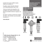
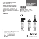
O P E R AT I N G I N S T R U C T I O N S PHT Druckmessumformer für die sterile Verfahrenstechnik Pressure Transmitter for Sanitary Applications D EN TYPE EL - CLASS I SEPTEMBER 2009 Betriebsanleitung Operating instructions Betriebsanleitung Inhalt / Contents / Sommaire / Índice Inhalt Seite 3 -20 D Contents Page 21 - 39 1. Allgemeines 1. General information 2. Der schnelle Überblick für Sie 2. A quick overview for you 3. Zeichenerklärungen, Abkürzungen 3. Abbreviations, signs and symbols 4. Funktion 4. Function 5. Zu Ihrer Sicherheit 5. For your safety 6. Verpackung 6. Packaging 7. Inbetriebnahme, Betrieb 7. Starting, operation 8. Einstellung Nullpunkt / Spanne 8. Adjustment of zero point / span 9. Wartung, Zubehör 9. Maintenance, accessories 10. Störbeseitigung 10. Trouble shooting 11. Lagerung, Entsorgung 11. Storage, disposal 2 © SICK AG • Deutschland • Alle Rechte vorbehalten PHT EN 8013362/2009/08/01 Betriebsanleitung 1. Allgemeines PHT 1. Allgemeines Der Druckmessumformer PHT ist speziell für die Anforderungen in der Nahrungs- und Genussmittelindustrie sowie pharmazeutischen Industrie und Biotechnologie konzipiert. Besonders für die im Rahmen von CIP/SIP-Reinigungsprozessen auftretenden Bedingungen, wie chemische Beständigkeit gegenüber Reinigungslösungen sowie erhöhte Temperaturen, ist der Druckmessumformer PHT sehr gut geeignet. Die frontbündige, metallische Messzelle ist mit dem Prozessanschluss direkt verschweißt. Somit ist eine spaltfreie Verbindung zwischen dem Prozessanschluss und der Messzelle realisiert, zusätzliche Dichtungen entfallen. Wichtiges zu Ihrer Information Das zugehörige Produkt-Datenblatt hat die Bezeichnung 8013359 Bei Sondertypen sind außerdem die Spezifikationen gemäß Lieferschein zu beachten. European Hygienic Engineering & Design Group Zeichenerklärung: TYPE EL - CLASS I SEPTEMBER 2009 Lesen Sie diese Betriebsanleitung vor Montage und Inbetriebnahme des Druckmessgerätes. Bewahren Sie die Betriebsanleitung an einem für alle Benutzer jederzeit zugänglichen Ort auf. Die nachfolgenden Einbau- und Betriebshinweise haben wir mit Sorgfalt zusammengestellt. Es ist jedoch nicht möglich, alle erdenklichen Anwendungsfälle zu berücksichtigen. Wird die Seriennummer unleserlich (z. B. durch mechanische Beschädigung oder Übermalen), ist eine Rückverfolgbarkeit nicht mehr möglich. Die in der Betriebsanleitung beschriebenen SICK-Druckmessgeräte werden nach den neuesten Erkenntnissen konstruiert und gefertigt. Alle Komponenten unterliegen während der Fertigung strengen Qualitäts- und Umweltkriterien. Unser Umweltmanagementsystem ist nach DIN EN ISO 14001 zertifiziert. 8013362/2009/08/01 © SICK AG • Deutschland • Alle Rechte vorbehalten 3 2. Der schnelle Überblick / Zeichenerklärungen, Abkürzungen Betriebsanleitung PHT Bestimmungsgemäße Produktverwendung Verwenden Sie den Druckmessumformer, um Druck in ein elektrisches Signal zu wandeln. Ihre erforderlichen Kenntnisse Montieren und nehmen Sie das Druckmessgerät nur in Betrieb, wenn Sie mit den zutreffenden landesspezifischen Richtlinien vertraut sind und die entsprechende Qualifikation besitzen. Sie müssen mit den Kenntnissen von Mess- und Regeltechnik sowie elektrischen Stromkreisen vertraut sein, da das Druckmessgerät ein „elektrisches Betriebsmittel“ nach EN 50178 ist. Je nach Einsatzbedingung müssen Sie über entsprechendes Wissen verfügen, z. B. über agressive Medien bzw. hohe Drücke. 2.Der schnelle Überblick für Sie Wollen Sie sich einen schnellen Überblick verschaffen, lesen Sie Kapitel 3, 5, 7 und 11. Dort erhalten Sie kurze Hinweise zu Ihrer Sicherheit und wichtige Informationen über Ihr Produkt und zur Inbetriebnahme. Lesen Sie diese unbedingt. 3.Zeichenerklärungen, Abkürzungen Warnung Warnung 4 Hinweis, wichtige Information, Funktionsstörung. Mögliche Gefahr von Verbrennungen durch heisse Oberflächen. Vorsicht 2-Leiter 3-Leiter Das Produkt stimmt mit den zutreffenden europäischen Richtlinien überein. Mögliche Gefahr für Ihr Leben oder schwerer Verletzungen. Mögliche Gefahr für Ihr Leben oder schwerer Verletzungen durch wegschleudernde Teile. Zwei Anschlussleitungen dienen zur Spannungsversorgung. Der Speisestrom ist das Mess-Signal. Zwei Anschlussleitungen dienen zur Spannungsversorgung. Eine Anschlussleitung dient für das Mess-Signal. © SICK AG • Deutschland • Alle Rechte vorbehalten 8013362/2009/08/01 5. Zu Ihrer Sicherheit Betriebsanleitung PHT 4.Funktion Mittels Sensorelement und unter Zuführung von Hilfsenergie wird über die Verformung einer Membran der anstehende Druck in Ihrer Anwendung in ein verstärktes standardisiertes elektrisches Signal umgewandelt. Dieses elektrische Signal verändert sich proportional zum Druck und kann entsprechend ausgewertet werden. 5.Zu Ihrer Sicherheit Wählen Sie das richtige Druckmessgerät hinsichtlich Messbereich, Ausführung und spezifischen Messbedingungen vor Montage oder Inbetriebnahme. Halten Sie die entsprechenden landesspezifischen Vorschriften ein (z. B.: EN Warnung 50178) und beachten Sie bei speziellen Anwendungen die geltenden Normen und Richtlinien (z. B. bei gefährlichen Messstoffen wie Acetylen, brennbaren oder giftigen Stoffen sowie bei Kälteanlagen und Kompressoren). Wenn Sie die entsprechenden Vorschriften nicht beachten, können schwere Körperverletzungen und Sachschäden entstehen! Öffnen Sie Anschlüsse nur im drucklosen Zustand! Betreiben Sie das Druckmessgerät immer innerhalb des Überlastgrenzbereiches! Beachten Sie die Betriebsparameter gemäß Punkt 7 „Technische Daten“. Beachten Sie die Technischen Daten zur Verwendung des Druckmessgerätes in Verbindung mit agressiven / korrosiven Medien und zur Vermeidung von mechanischen Gefährdungen. Stellen Sie sicher, dass das Druckmessgerät nur bestimmungsgemäß -also wie in der folgenden Anleitung beschrieben- betrieben wird. Unterlassen Sie unzulässige Eingriffe und Änderungen am Druckmessgerät, welche nicht in dieser Betriebsanleitung beschrieben sind. Setzen Sie das Druckmessgerät außer Betrieb und schützen Sie es gegen versehentliche Inbetriebnahme, wenn Sie Störungen nicht beseitigen können. Ergreifen Sie Vorsichtsmaßnahmen für Messstoffreste in ausgebauten Druckmessgeräten. Messstoffreste können zur Gefährdung von Menschen, Umwelt und Einrichtung führen! Lassen Sie Reparaturen nur vom Hersteller durchführen Öffnen Sie den Stromkreis, bevor Sie den Stecker / Deckel abnehmen. Es ist erforderlich, dass Sie vor Inbetriebnahme des Druckmessgerätes die Membran optisch prüfen, denn sie ist ein sicherheitsrelevantes Teil (siehe Abschnitt 7 unten). 8013362/2009/08/01 © SICK AG • Deutschland • Alle Rechte vorbehalten 5 6. Verpackung / 7. Inbetriebnahme, Betrieb Betriebsanleitung PHT 6.Verpackung Wurde alles geliefert? Überprüfen Sie den Lieferumfang: Komplett montierte Druckmessgeräte mit Schutzkappe. Entfernen Sie die Schutzkappe erst kurz vor dem Einbau, damit die Membran bzw. das Druckanschluss-Gewinde nicht beschädigt wird. Bewahren Sie die Schutzkappe des Druckanschluss-Gewindes und der Membran zur späteren Lagerung oder Transport auf. Montieren Sie die Schutzkappe bei Ausbau und Transport des Gerätes. Untersuchen Sie das Druckmessgerät auf eventuell entstandene Transportschäden. Sind offensichtlich Schäden vorhanden, teilen Sie dies dem Transportunternehmen und SICK unverzüglich mit. Bewahren Sie die Verpackung auf, denn diese bietet bei einem Transport einen optimalen Schutz (z. B. wechselnder Einbauort, Reparatursendung). Achten sie darauf, dass der Druckanschluss und die Anschlusskontakte nicht beschädigt werden. 7.Inbetriebnahme, Betrieb Membran-Prüfung zu Ihrer Sicherheit Benötigtes Werkzeug: Gegebenenfalls Schraubendreher Es ist erforderlich, dass Sie vor Inbetriebnahme des Druckmessgerätes die Membran optisch prüfen, denn sie ist ein sicherheitsrelevantes Teil. Achten Sie auf auslaufende Flüssigkeit, denn sie ist ein Hinweis auf eine Membranbeschädigung. Prüfen Sie die Membran optisch auf Beschädigung Warnung Setzen Sie das Druckmessgerät nur ein, wenn die Membran unbeschädigt ist. Setzen Sie das Druckmessgerät nur in sicherheitstechnisch einwandfreiem Zustand ein. 6 © SICK AG • Deutschland • Alle Rechte vorbehalten 8013362/2009/08/01 Betriebsanleitung 7. Inbetriebnahme, Betrieb PHT Montage mechanischer Anschluss Entfernen Sie die Schutzkappe erst kurz vor dem Einbau und achten Sie unbedingt darauf, dass die Membran auch während des Einbaus nicht beschädigt wird. Achten Sie bei der Montage auf saubere und unbeschädigte Dichtflächen am Gerät und Messstelle. Angaben zu den verfügbaren Prozessanschlüssen entnehmen Sie bitte dem PHT Datenblatt Nr. 8013359 Verwenden Sie für den jeweiligen Prozessanschluss geeignete Dichtungen. Typenschild (Beispiel) Serien-Nr. Bestell-Nr. 8013362/2009/08/01 © SICK AG • Deutschland • Alle Rechte vorbehalten 7 7. Inbetriebnahme, Betrieb Betriebsanleitung PHT Montage elektrischer Anschluss Erden Sie das Gerät über den Druckanschluss und/oder die Anschlussklemme 5. Betreiben Sie den Druckmessumformer mit geschirmter Leitung und erden Sie den Schirm auf mindestens einer Leitungsseite, wenn die Leitungen länger als 30m (2-Leiter) bzw. 3m (3- bzw. 4-Leiter) sind oder das Gebäude verlassen. Verwenden Sie ausschließlich Stromquellen, die eine sichere elektrische Trennung der Betriebsspannung nach IEC/DIN EN 60204-1 gewährleisten. Berücksichtigen Sie zusätzlich die allgemeinen Anforderungen an PELV-Stromkreise gemäß IEC/DIN EN 60204-1. Alternativ für Nordamerika: Der Anschluss kann auch an „Class 2 Circuits“ oder „Class 2 Power Units“ gemäß CEC ( Canadian Electrical Code) oder NEC (National Electrical Code) erfolgen. Schutzart IP nach IEC 60 529 (Die angegebenen Schutzarten gelten nur im gesteckten Zustand mit Leitungsteckern (Buchsen) entsprechender Schutzart). Wählen Sie den Kabeldurchmesser passend zur Kabeldurchführung des Steckers. Achten Sie darauf, dass die Kabelverschraubung des montierten Steckers korrekt sitzt und dass die Dichtungen vorhanden und nicht beschädigt sind. Ziehen Sie die Verschraubung fest und überprüfen Sie den korrekten Sitz der Dichtungen, um die Schutzart zu gewährleisten. Stellen Sie bei Kabelausgängen sicher, dass am Ende des Kabels keine Feuchtigkeit eintritt. 8 © SICK AG • Deutschland • Alle Rechte vorbehalten 8013362/2009/08/01 Betriebsanleitung 7. Inbetriebnahme, Betrieb Spannungsversorgung L+/QA M PHT Verbraucher Positiver Versorgungs- / Messanschluss Negativer Versorgungs- / Messanschluss 2-Leiter DIN EN 175301-803, Form A Winkelsteckverbinder, für Leitungsquerschnitt bis max. 1,5 mm², Leitungsaußendurchmesser 6 bis 8 mm, IP 65 3-Leiter L+/ QA L+ QA M M Rundsteckverbinder M 12x1, IP 67 QA L+ L+/ Q A M Kabelausgang mit 1,5 m Länge, Leitungsquerschnitt 0,5 mm ², AWG 20 mit Aderendhülsen, Leitungsaußendurchmesser 6,8 mm IP 68, ohne Zugang zu Nullpunkt und Spanne-Potentiometer L+/ Q A L+ braun braun QA schwarz M 8013362/2009/08/01 M M grün © SICK AG • Deutschland • Alle Rechte vorbehalten grün 9 Betriebsanleitung 7. Inbetriebnahme, Betrieb 2-Leiter PHT 3-Leiter L / QA + L+ Feldgehäuse, Leitungsaußendurchmesser 7 - 13 mm IP 67 M M Montage des Winkelsteckverbinder nach DIN EN 175301-803 Form A (D) Montageöffnung (2) QA (1) (3) (5) (4) Leitungsstecker (Buchse) 1. 2. 3. 4. 5. 10 Lösen Sie die Schraube (1). (6) Dichtung Lösen Sie die Kabelverschraubung (2). Ziehen Sie Winkelgehäuse (5)mit KlemmGriffring, block (6) vom Gerät ab. Gerätestecker(Stift), Hebeln Sie mit dem Schraubendreher in Gehäuse mit die Montageöffnung (D), so dass Sie den Druckanschluss Klemmblock (6) aus dem Winkelgehäuse (5) herausdrücken. Drücken Sie nicht den Klemmblock (6) durch die Schraubenöffnung (1) bzw. Kabelverschraubung (2) heraus, sonst beschädigen Sie die Dichtungen des Winkelgehäuses. Wählen Sie den Leitungsaußendurchmesser passend zur Kabeldurchführung des Winkel gehäuses. Schieben Sie das Kabel durch Kabelverschraubung (2), Ring (3), Dichtung (4) und Winkelgehäuse (5). © SICK AG • Deutschland • Alle Rechte vorbehalten 8013362/2009/08/01 7. Inbetriebnahme, Betrieb Betriebsanleitung PHT 6. Schließen Sie die Kabelenden entsprechend der Belegungszeichnung in den Anschluss klemmen des Klemmblocks (6) an. 7. Drücken Sie das Winkelgehäuse (5) auf den Klemmblock (6). 8. Verschrauben Sie das Kabel mit der Kabelverschraubung (2). Achten Sie darauf, dass die Dichtungen unbeschädigt sind und Kabelverschraubung und Dichtungen korrekt sitzen, um die Schutzart zu gewährleisten. 9. Legen Sie die quadratische Flachdichtung über die Anschlusspins im Gehäuse. 10.Schieben Sie den Klemmblock (6) auf die Anschlusspins im Gehäuse. 11.Verschrauben Sie mit der Schraube (1) das Winkelgehäuse (5) mit dem Klemmblock (6) im Gerät. Kabelanschluss im Federklemmblock Konfektionieren Sie die abgemantelten Aderenden mit Aderendhülsen. Schrauben Sie den Gehäusedeckel auf. Lösen Sie mit einem Maulschlüssel SW24 die Kabelverschraubung. Führen Sie das Kabel durch die Kabelverschraubung in den geöffneten Gehäusekopf. Drücken Sie den entsprechenden Kunststoffhebel am Federklemmblock mit einem Schraubendreher herunter, damit sich der Klemmkontakt öffnet. Führen Sie das konfektionierte Kabelende in die Öffnung ein und lassen den Kunststoff- hebel los, so dass das Kabelende im Federklemmblock eingeklemmt wird. Nach Anschließen der einzelnen Adern ziehen Sie die Kabelverschraubung fest und ver- schrauben den Gehäusedeckel. Funktion des Testkreises für 2-Leiter Anhand des Testkreises ist es möglich, während des normalen Betriebes eine Strommessung durchzuführen ohne das Gerät abzuklemmen. Sie müssen hierzu ein Amperemeter (Innenwiderstand < 15 Ohm) an die Klemmen Test +/- anschließen. 8013362/2009/08/01 © SICK AG • Deutschland • Alle Rechte vorbehalten 11 Betriebsanleitung PHT Messbereiche Einheit Messbereich Überlastgrenze Berstdruck Messbereich Überlastgrenze Berstdruck bar 0 ... 0,25 2 2,4 0 ... 4 17 20,5 0 ... 0,4 2 2,4 0 ... 6 35 42,0 0 ... 0,6 4 4,8 0 ... 10 35 42,0 0 ... 1 5 6,0 0 ... 16 80 96,0 0 ... 1,6 10 12,0 0 ... 25 80 96,0 0 ... 2,5 10 12,0 0 ... 0,25 2 2,4 0 ... 4 17 20,5 0 ... 0,4 2 2,4 0 ... 6 35 42,0 0 ... 1 5 6,0 0 ... 10 35 42,0 0 ... 1,6 10 12,0 0 ... 16 80 96,0 0 ... 2,5 10 12,0 -1 ... 0 5 6,0 -1 ... +5 35 42,0 -1 ... +0,6 10 12,0 -1 ... +9 35 42,0 -1 ... +3 17 20,5 -1 ... +15 80 96,0 bar abs bar Außerdem erhältlich: MPa, psi, kg/cm2 12 © SICK AG • Deutschland • Alle Rechte vorbehalten 8013362/2009/08/01 Betriebsanleitung 7. Inbetriebnahme, Betrieb PHT Technische Daten PHT Prozessanschlüsse Tri-Clamp 1 ½ " , 2 " Clamp DIN 32 676 DN 32, 40, 50 Clamp ISO 2852 DN 33,7, 38, 40, 51 Nutüberwurfmutter DIN 11 851 DN 25, 40, 50 Nutüberwurfmutter SMS DN 1 ½ " , 2 " VARIVENT® Form F, N Nutüberwurfmutter DIN 11 864-1, Flansch DIN 11 864-2, Clamp DIN 11 864-3 NEUMO BioControl® Größe 50, 65 NEUMO BioConnect® Form V - DN 40, 50 NEUMO BioConnect®, Bundstutzen zur Verschraubung, DN 40, 50 Flanschanschluss DRD Weitere Anschlüsse auf Anfrage Werkstoffe ■ Messstoffberührte Teile ■ Gehäuse Druckübertragungsflüssigkeit Hilfsenergie L+ Ausgangssignal und zulässige max. Bürde RA Einstellbarkeit Nullpunkt/ Spanne CrNi-Stahl 1.4435 CrNi-Stahl 1.4571 Synthetisches Öl, FDA konform 10 ... 30 V 14 ... 30 V bei Ausgangssignal 0 ... 10 V 11 ... 30 V bei Ausgangssignal 4 ... 20 mA und Feldgehäuse 4 ... 20 mA, 2-Leiter, RA ≤ (L+ – 10 V) / 0,02 A [Ohm] Bei Geräten mit Feldgehäuse und Ausgangssignal 4...20 mA ist ein Testkreisanschluss vorhanden, welcher eine unterbrechungsfreie Überprüfung des Messkreises bietet. 0 ... 10 V, 3-Leiter, RA > 10 kOhm 0...5 V, 3-Leiter, RA > 5 kOhm 5% durch Potentiometer im Gerät 1) 1) Nicht mit Kabelausgänge Bestellcodes 4 und 5 8013362/2009/08/01 © SICK AG • Deutschland • Alle Rechte vorbehalten 13 7. Inbetriebnahme, Betrieb Betriebsanleitung Technische Daten PHT Einstellzeit (10 ... 90 %) Spannungsfestigkeit Genauigkeit 3) ≤ 10 ms 500 VDC 2) ≤ ± 0,5 % d. Spanne, optional 0,25 % d. Spanne (kalibriert bei senkrechter Einbaulage, Druckanschluss unten) ≤ ± 0,2 % d. Spanne, (BFSL) nach IEC 61 298-2 ≤ ± 0,1 % d. Spanne ≤ ± 0,2 % d. Spanne (bei Referenzbedingungen) PHT Nichtlinearität Nichtwiederholbarkeit Stabilität pro Jahr Zulässige Temperaturbereiche -20 ... +150 °C ■ Messstoff 4) -20 ... +80 °C ■ Umgebung 4) -40 ... +100 °C ■ Lagerung 4) Kompensierter Temperaturbereich 0 ... +80 °C Temperaturkoeffizienten im kompensierten Temperaturbereich ■ Mittlerer TK des Nullpunktes ≤ 0,2 % d. Spanne/ 10 K, für Messbereich 0 ... 0,6 bar bis 0 ... 25 bar ≤ 0,25 % d. Spanne/ 10 K, für Messbereich 0 ... 0,4 bar ≤ 0,4 % d. Spanne/ 10 K, für Messbereich 0 ... 0,25 bar ■ Mittlerer TK der Spanne ≤ 0,2 % d. Spanne/ 10 K CE-Konformität ■ EMV-Richtlinie 2004/108/EG, EN 61326-2-3 Schockbelastbarkeit 500 g nach IEC 60068-2-27, (Schock mechanisch) Vibrationsbelastbarkeit 15 g nach IEC 60068-2-6, (Vibration bei Resonanz) Elektrischer Anschluss Winkelsteckverbinder, 4-polig, EN 175301-803, Form A CrNi-Stahl Feldgehäuse mit innenliegenden Federklemmen, Anschlussquerschnitt max. 2,5 mm2 Rundsteckverbinder, 4-polig, mit Schraubverschluss M12 x 1 Kabelausgang mit 1,5 m oder 3 m innenbelüftetem Kabel (Nullpunkt und Spanne nicht einstellbar). Andere Längen auf Anfrage 2) NEC Class 02 Spannungsversorgung (Niederspannung und Niederstrom max. 100 VA auch im Fehlerzustand) 3) Einschließlich Nichtlinearität, Hysterese, Nullpunkt- und Endwertabweichung (entspricht Messabweichung nach IEC 61 298-2) 4) Erfüllt auch EN 50178, Tab. 7, Betrieb (C) 4K4H, Lagerung (D) 1K4, Transport (E) 2K3 14 © SICK AG • Deutschland • Alle Rechte vorbehalten 8013362/2009/08/01 Betriebsanleitung 7. Inbetriebnahme, Betrieb Technische Daten PHT PHT Elektrische Schutzarten ■ Schutzklasse ■ Überspannungsschutz ■ Kurzschlussfestigkeit ■ Verpolschutz ■ Schutzart Gewicht III 36 VDC QA gegen M L+ gegen M Nach IEC 60 529 / EN 60 529 (siehe elektrischer Anschluss). Die angegebenen Schutzarten gelten nur im gesteckten Zustand mit Leitungssteckern entsprechender Schutzart Ca. 0,5 kg (ca. 0,6 bei Option Kennlinienabweichung 0,25% der Spanne) Beachten Sie bei der Auslegung Ihrer Anlage, dass die angegebenen Werte (z. B. Berstdruck, Überlastgrenze) in Abhängigkeit vom verwendeten Material, Prozessanschluss, Anschlussfittings und Dichtung gelten. Funktionsprüfung Das Ausgangssignal muss sich dem anstehenden Druck proportional verhalten. Wenn dies nicht so ist, kann das ein Hinweis auf eine Beschädigung der Membran sein. Lesen Sie in diesem Fall in Kapitel 10 „Störbeseitigung“ nach. Öffnen Sie Anschlüsse nur im drucklosen Zustand! Beachten Sie die Betriebsparameter gemäß Punkt 7„Technische Daten“. Betreiben Sie das Druckmessgerät immer innerhalb des Überlastgrenzbereichs! Warnung Vorsicht Beachten Sie beim Berühren des Druckmessgerätes, dass die Oberflächen der Gerätekomponenten während des Betriebes heiß werden können. 8013362/2009/08/01 © SICK AG • Deutschland • Alle Rechte vorbehalten 15 8. Einstellung Nullpunkt / Spanne Betriebsanleitung PHT 8.Einstellung Nullpunkt / Spanne (nur bei Geräten mit Griffring oder mit Feldgehäuse) Wir empfehlen Ihnen, das Spannepotentiometer nicht zu verstellen. Es dient zur werkseitigen Justage und sollte nur von Ihnen verstellt werden, wenn Sie über die ausreichende Kalibrierausstattung (mindestens 3x genauer als die angegebene Genauigkeit) verfügen. Geräte mit Griffring Achten Sie bei der Steckerdemontage /- montage darauf, dass keine Litzen abgerissen bzw. eingequetscht werden. Ziehen Sie den Leitungstecker (Buchse) ab. Öffnen Sie das Druckmessgerät, indem Sie den Griffring lösen (siehe Abbildung A ). Ziehen Sie vorsichtig den Gerätestecker (Stift) aus dem Gehäuse. Stellen Sie den Nullpunkt (Z) ein (siehe Abbildung B ), indem Sie den Druckan- fangswert anfahren. Stellen Sie die Spanne (S) ein, indem Sie den Druckendwert anfahren. Überprüfen Sie den Nullpunkt. Wenn der Nullpunkt nicht stimmt ggf. Prozedur wiederholen. Schließen Sie das Druckmessgerät wieder sorgfältig. Achten Sie darauf, dass die Dichtungen unbeschädigt und sauber sind und auf die korrekte Lage der Dich- tungen, um die Schutzart zu gewährleisten. Leitungsstecker (Buchse) B Dichtung Griffring Gerätestecker (Stift) Dichtung A Gehäuse mit Druckanschluss Z = Nullpunkt S = Spanne Empfohlener Nachkalibrier-Zyklus: 1 Jahr 16 © SICK AG • Deutschland • Alle Rechte vorbehalten 8013362/2009/08/01 Betriebsanleitung 8. Einstellung Nullpunkt / Spanne Geräte mit Feldgehäuse Achten Sie bei der Steckerdemontage /- montage darauf, dass keine Litzen abgerissen bzw. eingequetscht werden. Öffnen Sie das Druckmessgerät, indem Sie das Feldgehäuse aufdrehen. Stellen Sie den Nullpunkt (Z) ein, indem Sie den Druckanfangswert anfahren. Stellen Sie die Spanne (S) ein, indem Sie den Druckendwert anfahren. Überprüfen Sie den Nullpunkt. Wenn der Nullpunkt nicht stimmt ggf. Prozedur wiederholen. Schließen Sie das Druckmessgerät wieder sorgfältig. Achten Sie darauf, dass die Dichtungen unbeschädigt und sauber sind und auf die korrekte Lage der Dichtungen, um die Schutzart zu gewährleisten. 8013362/2009/08/01 PHT S = Spanne Z = Nullpunkt © SICK AG • Deutschland • Alle Rechte vorbehalten 17 9. Wartung, Zubehör / 10. Störbeseitigung Betriebsanleitung PHT 9.Wartung, Zubehör SICK Druckmessgeräte sind wartungsfrei. Lassen Sie Reparaturen nur vom Hersteller durchführen. Zubehör Entnehmen Sie bitte Zubehörangaben (z. B. Kabel) unserem aktuellen Datenblatt oder setzen Sie sich mit unserem Vertriebsmitarbeiter in Verbindung. 10.Störbeseitigung Warnung Warnung Öffnen Sie Anschlüsse nur im drucklosen Zustand! Ergreifen Sie Vorsichtsmaßnahmen für Messstoffreste in ausgebauten Druckmessgeräten. Messstoffreste können zur Gefährdung von Menschen, Umwelt und Einrichtung führen! Setzen Sie das Druckmessgerät außer Betrieb und schützen Sie es gegen versehentliche Inbetriebnahme, wenn Sie Störungen nicht beseitigen können. Lassen Sie Reparaturen nur vom Hersteller durchführen. Verwenden Sie keine spitzen bzw. harten Gegenstände zur Reinigung, denn die Membran des Druckanschlusses darf nicht beschädigt werden. Prüfen Sie bitte vorab, ob Druck ansteht (Ventile/Kugelhahn usw. offen) und ob Sie die richtige Spannungsversorgung und die richtige Verdrahtungsart (2-Leiter/3-Leiter) gewählt haben. 18 © SICK AG • Deutschland • Alle Rechte vorbehalten 8013362/2009/08/01 10. Störbeseitigung Betriebsanleitung Störung Kein Ausgangssignal Mögliche Ursache Maßnahme PHT Leitungsbruch Durchgang überprüfen Keine/Falsche Versorgungsspannung oder Stromstoß Versorgungsspannung gemäß Betriebsanleitung korrigieren *) Kein/Falsches Ausgangssignal Verdrahtungsfehler (z. B. 2-Leiter als 3-Leiter verdrahtet) Pinbelegung beachten (Typenschild und Bedienungsanleitung) Gleichbleibendes Ausgangssignal bei Druckänderung Mechanische Überlastung durch Überdruck Gerät austauschen; bei wiederholtem Ausfall Rücksprache mit Hersteller *) Signalspanne zu klein / fällt ab Mechanische Überlastung durch Überdruck Gerät austauschen; bei wiederholtem Ausfall Rücksprache mit Hersteller *) Membranbeschädigung, z. B. durch Hersteller kontaktieren und Gerät austauSchläge, abrasives/agressives Medium; schen Korrosion an Membran/Druckanschluss; Übertragungsmedium fehlt Signalspanne schwankend / ungenau Abweichendes Nullpunkt-Signal Dichtung/Dichtfläche beschädigt/ verschmutzt, Dichtung sitzt unkorrekt, Gewindegänge verkantet Dichtung/-Fläche säubern, evtl. Dichtung austauschen EMV-Störquellen in Umgebung, z. B. Frequenzumrichter Gerät abschirmen; Leitungsabschirmung; Störquelle entfernen Zu hohe/niedrige Einsatztemperaturen Zulässige Temperaturen gemäß Betriebsanleitung einhalten Gerät nicht geerdet Gerät erden Stark schwankender Druck des Prozessmediums Dämpfung; Beratung durch Hersteller Zu hohe/niedrige Einsatztemperaturen Zulässige Temperaturen gemäß Betriebsanleitung einhalten Abweichende Einbaulage Nullpunkt mittels Potentiometer oder Bedienfeld oder Software korrigieren Überlastgrenze überschritten Zulässige Überlastgrenze einhalten (siehe Betriebsanleitung)) *) Überprüfen Sie nach dem Justieren die korrekte Arbeitsweise des Systems. Besteht der Fehler weiterhin, senden Sie das Gerät zur Reparatur ein (oder tauschen Sie das Gerät aus). Wenn das Problem bestehen bleibt, setzen Sie sich mit unserem Vertriebsmitarbeiter in Verbindung. 8013362/2009/08/01 © SICK AG • Deutschland • Alle Rechte vorbehalten 19 11. Lagerung, Entsorgung Betriebsanleitung PHT Unbedenklichkeitserklärung im Servicefall Spülen bzw. säubern Sie ausgebaute Geräte vor der Rücksendung, um unsere Mitarbeiter und die Umwelt vor Gefährdung durch anhaftende Messstoffreste zu schützen. Eine Überprüfung ausgefallener Geräte kann nur sicher erfolgen, wenn die vollständig ausgefüllte Unbedenklichkeitserklärung vorliegt. Eine solche Erklärung beinhaltet alle Materialien, welche mit dem Gerät in Berührung kamen, auch solche, die zu Testzwecken, zum Betrieb oder zur Reinigung eingesetzt wurden. Das Unbedenklichkeitserklärung ist über unsere Internet-Adresse (www. SICK.com) verfügbar. 11.Lagerung, Entsorgung Ergreifen Sie bei Lagerung und Entsorgung Vorsichtsmaßnahmen für Messstoffreste in ausgebauten Druckmessgeräten. Wir empfehlen eine geeignete und sorgfältige Reinigung. Messstoffreste können zur Gefährdung von Menschen, Umwelt und Einrichtung führen! Warnung Lagerung Montieren Sie die Schutzkappe bei Lagerung des Druckmessgerätes, damit die Membran nicht beschädigt wird. Entsorgung Entsorgen Sie Gerätekomponenten und Verpackungsmaterialien entsprechend den einschlägigen landesspezifischen Abfallbehandlungs- und Entsorgungsvorschriften des Anliefergebietes. Technische Änderungen vorbehalten. 20 © SICK AG • Deutschland • Alle Rechte vorbehalten 8013362/2009/08/01 Operating Instructions 1. General information / 2. Important information PHT 1. General information The PHT pressure transmitter has been designed specifically for the requirements of the food and beverage, pharmaceutical and biotechnology industries. The PHT pressure transmitter is particularly suited to the conditions of CIP/SIP cleaning processes due to its chemical resistance towards cleaning fluids and high temperatures. The flush, metal measuring cell is welded directly to the process connection. This guarantees a crevice-free junction between the process connection and the measuring cell; no additional seals are required. Important information The corresponding data sheet is 8013360 For special versions please also observe the specifications in the delivery note. Key to symbols: European Hygienic Engineering & Design Group TYPE EL - CLASS I SEPTEMBER 2009 Read these operating instructions before installing and starting the pressure transmitter. Keep the operating instructions in a place that is accessible to all users at any time. The following installation and operating instructions have been compiled by us with great care but it is not feasible to take all possible applications into consideration. These installation and operation instructions should meet the needs of most pressure measurement applications. If the serial number gets illegible (e.g. by mechanical damage or repainting), the retraceability of the instrument is not possible any more. 8013362/ 2009/08/01 © SICK AG • Germany • All rights reserved 21 Operating Instructions 2. A quick overview for you PHT SICK pressure transmitters are carefully designed and manufactured using state-of-the-art technology. Every component undergoes strict quality and environmental inspection before assembly and each instrument is fully tested prior to shipment. Our environmental management system is certified to DIN EN ISO 14001. Use of the product in accordance with the intended use Use the pressure transmitter to transform the pressure into an electrical signal. Knowledge required Install and start the pressure transmitter only if you are familiar with the relevant regulations and directives of your country and if you have the qualification required. You have to be acquainted with the rules and regulations on measurement and control technology and electric circuits, since this pressure transmitter is „electrical equipment“ as defined by EN 50178. Depending on the operating conditions of your application you have to have the corresponding knowledge, e.g. of aggressive media. 2.A quick overview for you If you want to get a quick overview, read Chapters 3, 5, 7 and 11. There you will get some short safety instructions and important information on your product and its starting. Read these chapters in any case. 22 © SICK AG • Germany • All rights reserved 8013362/2009/08/01 Operating Instructions 3. Signs, symbols and abbreviations / 4. Function PHT 3.Abbreviations, signs and symbols Potential danger of life or of severe injuries. Warning Warning Potential danger of life or of severe injuries due to catapulting parts. The product complies with the applicable European directives. Notice, important information, malfunction. Potential danger of burns due to hot surfaces. Caution 2-wire 3-wire Two connection lines are intended for the voltage supply. The supply current is the measurement signal. Two connection lines are intended for the voltage supply. One connection line is intended for the measurement signal. 4.Function The pressure prevailing within the application is transformed into a standardised electrical signal through the deflection of the diaphragm, which acts on the sensor element with the power supply fed to the transmitter. This electric signal changes in proportion to the pressure and can be evaluated correspondingly. 8013362/ 2009/08/01 © SICK AG • Germany • All rights reserved 23 Operating Instructions 5. For your safety PHT 5.For your safety Select the appropriate pressure transmitter with regard to scale range, performance and specific measurement conditions prior to installing and starting the instrument. Warning Observe the relevant national regulations (e.g.: EN 50178) and observe the applicable standards and directives for special applications (e.g. with dangerous media such as acetylene, flammable gases or liquids and toxic gases or liquids and with refrigeration plants or compressors). If you do not observe the appropriate regulations, serious injuries and/or damage can occur! Open pressure connections only after the system is without pressure! Please make sure that the pressure transmitter is only used within the overload threshold limit all the time! Observe the ambient and working conditions outlined in section 7 “Technical data”. Observe the technical data for the use of the pressure transmitter in connection with aggressive / corrosive media and for the avoidance of mechanical hazards. Ensure that the pressure transmitter is only operated in accordance with the provisions i.e. as described in the following instructions. Do not interfere with or change the pressure transmitter in any other way than described in these operating instructions. Remove the pressure transmitter from service and mark it to prevent it from being used again accidentally, if it becomes damaged or unsafe for operation Take precautions with regard to remaining media at removed pressure transmitter. Remaining media at the device may be hazardous or toxic! Have repairs performed by the manufacturer only. Open circuit before removing connector / cover. It is necessary that before starting the pressure transmitter you check the diaphragm visually, as this is a safety-relevant component (Please refer to section 7 below). 24 © SICK AG • Germany • All rights reserved 8013362/2009/08/01 Operating Instructions 6. Packaging / 7. Starting, operation PHT 6.Packaging Has everything been supplied? Check the scope of supply: Completely assembled pressure transmitters with protection cap. Remove this protection cap only just before installing the pressure transmitter in order to prevent any damage to the diaphragm or the thread. Keep the protection cap of the pressure connection thread and the diaphragm for later storage or transport. Mount the protection cap when removing and transporting the instrument. Inspect the pressure transmitter for possible damage during transportation. Should there be any obvious damage, inform the transport company and SICK without delay. Keep the packaging, as it offers optimal protection during transportation (e.g. changing installation location, shipment for repair). Ensure that the pressure connection and the connection contacts will not be damaged. 7.Starting, operation Required tools: screw driver if applicable Diaphragm test for your safety It is necessary that before starting the pressure transmitter you test the diaphragm visually, as this is a safety-relevant component. Pay attention to any liquid leaking out, for this points to a diaphragm damage. Check the diaphragm visually for any damage. Use the pressure transmitter only if the diaphragm is undamaged. Warning Use the pressure transmitter only if it is in a faultless condition as far as the safety-relevant features are concerned. 8013362/ 2009/08/01 © SICK AG • Germany • All rights reserved 25 Operating Instructions 7. Starting, operation PHT Mechanical connection Remove the protection cap only just before installation and absolutely avoid any damage to the diaphragm during installation as well. When mounting the instrument, ensure that the sealing faces of the instrument and the measuring point are clean and undamaged. For process connections please see data sheet 8013360. Use appropriate sealings for the process connection in use Product label (example) Serial No. Part No. 26 © SICK AG • Germany • All rights reserved 8013362/2009/08/01 Operating Instructions 7. Starting, operation PHT Electrical connection Connect the instrument to earth via the pressure connection and/or connection terminal 5. Operate the pressure transmitter with a shielded cable and earth the shield at least on one side of the cable, if the cable is longer than 30m (2-wire) or 3m (3- or 4-wire), or if it is run outside of the building. Use power supplies which guarantee reliable electrical isolation of the operating voltage as per IEC/DIN EN 60204-1. Consider also the general requirements for PELV circuits in accordance with IEC/DIN EN 60204-1. Alternative for North America: The connection may also be made to „Class 2 Circuits“ or „Class 2 Power Units“ according to CEC (Canadian Electrical Code) or NEC (National Electrical Code. Ingress protection per IEC 60529 (The ingress protection classes specified only apply while the pressure transmitter is connected with female connectors that provide the corresponding ingress protection). Ensure that the cable diameter you select fits to the cable gland of the connector. Ensure that the cable gland of the mounted connector is positioned correctly and that the sealings are available and undamaged. Tighten the threaded connection and check the correct position of the sealings in order to ensure the ingress protection. Please make sure that the ends of cables with flying leads do not allow any ingress of moisture. 8013362/ 2009/08/01 © SICK AG • Germany • All rights reserved 27 Operating Instructions 7. Starting, operation Power supply L+/QA M Load (e.g. display) Positive supply / measurement connection Negative supply / measurement connection 2-wire DIN 175301-803 A L-Connector, for conducter cross section up to max. 1,5 mm², conducter outer diameter 6 up to 8 mm, IP 65 3-wire L / QA + L+ QA M M L+ L+/ QA Circular connector M 12x1, IP 67 M Flying leads with 1.5 m of cable, conducter cross section up to max. 0.5 mm ², AWG 20 with end splices, conducter outer diameter 6.8 mm, IP 68, zero/span not adjustable L +/ QA QA M L+ brown QA M 28 PHT © SICK AG • Germany • All rights reserved green brown white M 8013362/2009/08/01 green Operating Instructions 7. Starting, operation 2-wire L+/ Q A PHT 3-wire L+ Field case version, conductor outer diameter 7 - 13 mm IP 67 M QA M Assembly of L-connector DIN EN 175301-803 Form A (D) Mounting hole (2) (1) (3) (4) (5) Female connector 1. 2. 3. 4. Loosen the screw (1). (6) Loosen the cable gland (2). Sealing Pull the angle housing (5), with the Clamping nut, terminal block (6) inside, away from the Male connector, instrument. Case with Using the head of a small screwdriver in pressure connection the mounting hole (D), lever the terminal block (6) out of the angle housing (5). In order not to damage the sealing of the angle housing, do not try to push the terminal block (6) out using the screw hole (1) or the cable gland (2). 8013362/ 2009/08/01 © SICK AG • Germany • All rights reserved 29 7. Starting, operation Operating Instructions PHT 5. Ensure that the conductor outer diameter you select is matched to the angle housing’s cable gland. Slide the cable through the cable gland nut (2), washer (3), gland seal (4) and angle housing (5). 6. Connect the flying leads to the screw terminals on the terminal block (6) in accordance with the pin-assignment drawing. 7. Press the terminal block (6) back into the angle housing (5). 8. Tighten the cable gland (2) around the cable. Make sure that the sealing isn’t damaged and that the cable gland and seals are assembled correctly in order to ensure ingress protection. 9. Place the flat, square gasket over the connection pins on the top of the instrument housing. 10.Slide the terminal block (6) onto the connection pins. 11.Secure the angle housing (5) and terminal block (6) to the instrument with the screw (1). Cable connection in the spring clip terminal Cover the stripped wire ends with end splices. Unscrew the case cover. Loosen the cable gland using an open-end wrench, wrench size 24. Lead the cable through the cable gland into the opened case head. Press the corresponding plastic lever at the spring clip terminal down using a screw driver, so that the clamped contact will be released. Lead the prepared flying lead into the opening and let go of the plastic lever, so that the flying lead will be squeezed inside the spring clip terminal. After connecting the individual wires, tighten the cable gland and screw down the case over. Function of the test circuit for 2-wire By means of the test circuit the current can be metered during normal operation without having to disconnect the instrument. For that purpose you have to connect an ammeter (internal resistance < 15 Ohm) to the test +/- terminals 30 © SICK AG • Germany • All rights reserved 8013362/2009/08/01 Operating Instructions 7. Starting, operation PHT Measuring ranges Unit Pressure ranges Overpressure safety Burst pressure Pressure ranges Overpressure safety Burst pressure bar 0 ... 0.25 2 2.4 0 ... 4 17 20.5 0 ... 0.4 2 2.4 0 ... 6 35 42.0 0 ... 0.6 4 4.8 0 ... 10 35 42.0 0 ... 1 5 6.0 0 ... 16 80 96.0 0 ... 1.6 10 12.0 0 ... 25 80 96.0 0 ... 2.5 10 12.0 2 2.4 0 ... 4 17 20.5 0 ... 0.4 2 2.4 0 ... 6 35 42.0 0 ... 1 5 6.0 0 ... 10 35 42.0 0 ... 1.6 10 12.0 0 ... 16 80 96.0 0 ... 2.5 10 12.0 -1 ... 0 5 6.0 -1 ... +5 35 42.0 -1 ... +0.6 10 12.0 -1 ... +9 35 42.0 -1 ... +3 17 20.5 -1 ... +15 80 96.0 bar abs 0 ... 0.25 bar Also available: MPa, psi, kg/cm2 8013362/ 2009/08/01 © SICK AG • Germany • All rights reserved 31 Operating Instructions 7. Starting, operation Technical Data PHT Process connections Tri-Clamp 1 ½ " , 2 " PHT Clamp DIN 32 676 DN 32, 40, 50 Clamp ISO 2852 DN 33,7, 38, 40, 51 Female union nut DIN 11 851 DN 25, 40, 50 Female union nut SMS DN 1 ½ " , 2 " VARIVENT® form F, N Female union nut DIN 11 864-1, flange DIN 11 864-2, clamp DIN 11 864-3 NEUMO BioControl® size 50, 65 NEUMO BioConnect® form V - DN 40, 50 NEUMO BioConnect® thread with union nut DN 40, 50 Flange connection DRD Further connections on request Materials ■ Wetted parts Stainless steel 1.4435 ■ Case Stainless steel 1.4571 Pressure transmitting fluid Synthetic oil, FDA approved 10 ... 30 V 14 ... 30 with signal output 0 ... 10 V 11 ... 30 V with signal output 4 ... 20 mA and field housing Signal output and maximum 4 ... 20 mA, 2-wire, RA ≤ (L+ – 10 V) / 0.02 A [Ohm] The variant with field housing and current output 4…20 mA features test termiload RA nals that allow metering of the signal current without having to disconnect the device. 0 ... 10 V, 3-wire, RA > 10 kOhm Power supply L + 0 ... 5 V, 3-wire, RA > 5 kOhm 32 © SICK AG • Germany • All rights reserved 8013362/2009/08/01 Operating Instructions 7. Starting, operation Technical Data PHT Adjustability zero/span 5 % using potentiometers inside the instrument 1) Response time (10 ... 90 %) ≤ 10 ms Dielectric strength 500 V DC 2) Accuracy Non-linearity ≤ ± 0.5 % of span, optional 0.25 % of span (adjusted in vertical mounting position with lower pressure connection) ≤ ± 0.2 % of span (BFSL) per IEC 61298-2 Non-repeatability ≤ ± 0.1 % of span 1-year stability ≤ ± 0.2 % of span (at reference conditions) 3) PHT Permissible temperature ranges ■ Medium -20 ... +150°C 4) ■ Ambient -20 ... +80°C ■ Storage 4) -40 ... +100°C Compensated temperature range Temperature coefficients within compensated temperature range: ■ Mean TC of zero 0 ... +80 °C 4) ≤ 0.2 % of span/ 10 K, with pressure ranges 0 ... 0.6 bar to 0 ... 25 bar ≤ 0.25 % of span/ 10 K, with pressure range 0 ... 0.4 bar ≤ 0.4 % of span/ 10 K, with pressure range 0 ... 0.25 bar ■ Mean TC of range ≤ 0.2 % of span/ 10 K CE-conformity ■ EMC directive 2004/108/EEC, EN 61 326-2-3 1) Not with cable connections order codes 4 and 5 2) NEC Class 02 power supply (low voltage and low current max. 100 VA even under fault conditions) 3) Including non-linearity, hysteresis, zero point and full scale error (corresponds to error of measurement per IEC 61298-2) 4) Also complies with EN 50178, Tab. 7, Operation (C) 4K4H, Storage (D) 1K4, Transport (E) 2K3 8013362/ 2009/08/01 © SICK AG • Germany • All rights reserved 33 Operating Instructions 7. Starting, operation PHT Technical Data PHT Shock resistance Vibration resistance Electrical connection 500g per IEC 60068-2-27, (mechanical shock) 15g per IEC 60068-2-6, (vibration under resonance) 4-pin L-connector per EN 175301-803, form A Stainless steel field case with internal spring clip terminal, cross section max. 2.5 mm2 Circular connector M12 x 1, 4-pin Flying lead with 1,5 m or 3 m vented cable (zero/span not adjustable) Further lengths on request Wiring protection ■ Protection class ■ Wiring protection ■ Overvoltage protection ■ Short-circuit proofness ■ Ingress protection Weight III 36 V DC QA towards M L+ towards M Per IEC 60 529 / EN 60 529 (see Electrical connections) The ingress protection classes specified only apply when the pressure transmitter is connected with female connectors that provide the corresponding ingress protection Approx. 0.5 kg (ca. 0.6 kg with option accuracy 0.25 % of span) When designing your plant, take into account that the stated values (e.g.burst pressure, over pressure safety) apply depending on the material, process connection, fittings and sealing element used. Functional test The output signal must be proportional to the pressure. If not, this might point to a damage of the diaphragm. In that case refer to chapter 10 “Troubleshooting“. Open pressure connections only after the system is without pressure! Observe the ambient and working conditions outlined in section 7 “Technical data". Please make sure that the pressure transmitter is only used within the overWarning load threshold limit at all times! When touching the pressure transmitter, keep in mind that the surfaces of the instrument components might get hot during operation. Caution 34 © SICK AG • Germany • All rights reserved 8013362/2009/08/01 Operating Instructions 8. Adjustment of zero point / span PHT 8.Adjustment of zero point / span (only for pressure transmitter with clamping nut or field housing) We do not recommend to adjust the span potentiometer. It is used for adjustment ex factory and should not be adjusted by you unless you have adequate calibration equipment at your disposal (at least three times more accurate than the instrument being tested). Devices with clamping nut Make sure wires are not cut or pinche during disassembly and reassembly of the connector. Remove the female connector. Open the pressure transmitter by detaching the clamping nut (see Fig. A ). Carefully remove the male connector from the case. Adjust the zero point (Z) (see Fig. B ) by generating the lower limit of the pressure range. Adjust the span (S) by generating the higher limit of the pressure range. Check the zero point. If the zero point is incorrect, repeat procedure as required. Reassemble the instrument carefully. Make sure all sealings and o-rings are not damaged and correctly installed to assure the rated moisture ingress protection. 8013362/ 2009/08/01 Female connector B Sealing Clamping nut Male connector Sealing S = Span A Z = Zero Case with pressure connection © SICK AG • Germany • All rights reserved 35 8. Adjustment of zero point / span Operating Instructions Devices with field housing Make sure wires are not cut or pinche during disassembly and reassembly of the connector. Open the pressure transmitter by twisting off the field case over. Adjust the zero point (Z) by generating the lower limit of the pressure range. Adjust the span (S) by generating the higher limit of the pressure range. Check the zero point. If the zero point is incorrect, repeat procedure as required. Reassemble the instrument carefully. Make sure all sealings and O-rings are not damaged and correctly installed to assure the rated moisture ingress protection. 36 © SICK AG • Germany • All rights reserved S = Span Z = Zero 8013362/2009/08/01 PHT Operating Instructions 9. Maintenance, accessories /10. Trouble shooting PHT 9.Maintenance, accessories SICK pressure transmitters require no maintenance. Have repairs performed by the manufacturer only. Accessories For details about the accessories (e. g. cables), please refer to PHT data sheet, or contact our sales department. 10.Trouble shooting Open pressure connections only after the system is without pressure! Warning Warning Take precautions with regard to remaining media at removed pressure transmitters. Remaining media at the device may be hazardous or toxic! Remove the pressure transmitter from service and mark it to prevent it from being used again accidentally, if it becomes damaged or unsafe for operation. Have repairs performed by the manufacturer only. Do not use any pointed or hard objects for cleaning to prevent damage to the diaphragm of the pressure connection. Please verify in advance if pressure is being applied (valves/ ball valve etc. open) and if the right voltage supply and the right type of wiring (2-wire/ 3-wire) has been chosen? 8013362/ 2009/08/01 © SICK AG • Germany • All rights reserved 37 Operating Instructions 10. Trouble shooting Failure No output signal PHT Possible cause Procedure Cable break Check connections and cable No/incorrect voltage supply or current spike Adjust the voltage supply to correspond with the Operating Instructions *) No/False output signal Incorrectly wired (e.g. Connected as 2-wire Follow pin assignment (see Instrument instead of 3-wire system) Label / Operating Instructions) Output signal unchanged after change in pressure Mechanical overload through overpressure Replace instrument; if failure reoccurs, consult the manufacturer *) Signal span dropping off/too small Mechanical overload through overpressure Replace instrument; if failure reoccurs, consult the manufacturer *) Diaphragm is damaged, e.g. through Contact the manufacturer and replace the impact, abrasive/agressive media; corro- instrument sion of diaphragm/pressure connector; transmission fluid missing. Signal span erratic / incorrect Seal/Sealing face damaged/contaminated, seal mounted incorrectly, threads crossed Clean the seal/sealing face, possibly replace the seal. Electromagnetic interference source in the vicinity, e.g. inverter drive Shield the device; shield the cables; remove the interference source Working temperature too high/too low Ensure permissible temperatures as per the Operating Instructions Instrument not grounded Ground instrument Violent fluctuations in the process media Damping; consult with manufacturer pressure Abnormal zero point signal Working temperature too high/too low Ensure permissible temperatures as per the Operating Instructions Abnormal mounting position Correct the zero point through the potentiometer, control panel or software Overload limits exceeded Ensure permissible overload limits are observed (see Operating Instructions) *) *) Make sure that after the setting the unit is working properly. In case the error continues to exist send in the instrument for repair (or replace the unit). If the problem persists, contact our sales department. 38 © SICK AG • Germany • All rights reserved 8013362/2009/08/01 Operating Instructions 10. Trouble shooting / 11. Storage, disposal PHT Non-risk declaration Purge / clean dismounted instruments before returning them in order to protect our employees and the environment from any hazard caused by adherent remaining media. Service of instruments can only take place safely when a non-risk declaration has been submitted and fully filled-in. This non-risk declaration contains information on all materials with which the instrument has come into contact, either through installation, test purposes, or cleaning. You can find the non-risk declaration on our internet site (www.SICK.com). 11.Storage, disposal Warning When storing or disposing of the pressure transmitter, take precautions with regard to remaining media at the removed pressure transmitters. We recommend cleaning the transmitter properly and carefully. Remaining media at the device may be hazardous or toxic! Storage Mount the protection cap when storing the pressure transmitter in order to prevent any damage to the diaphragm. Disposal Dispose of instrument components and packaging materials in accordance with the respective waste treatment and disposal regulations of the region or country to which the instrument is supplied. SICK reserves the right to alter these technical specifications. 8013362/ 2009/08/01 © SICK AG • Germany • All rights reserved 39 8013362/2009-08-01 ∙ DIV09/FD ∙ Printed in Germany (2009-03) ∙ Subject to change without notice The specified product featur and technical data do not represent any guarantee ∙ SICK AG Australia Phone +61 3 9497 4100 1800 33 48 02 – tollfree E-Mail [email protected] Belgium/Luxembourg Phone +32 (0)2 466 55 66 E-Mail [email protected] Brasil Phone +55 11 3215-4900 E-Mail [email protected] Ceská Republika Phone +420 2 57 91 18 50 E-Mail [email protected] China Phone +852-2763 6966 E-Mail [email protected] Danmark Phone +45 45 82 64 00 E-Mail [email protected] Deutschland Phone +49 211 5301-301 E-Mail [email protected] España Phone +34 93 480 31 00 E-Mail [email protected] France Phone +33 1 64 62 35 00 E-Mail [email protected] Great Britain Phone +44 (0)1727 831121 E-Mail [email protected] India Phone +91–22–4033 8333 E-Mail [email protected] Israel Phone +972-4-999-0590 E-Mail [email protected] Italia Phone +39 02 27 43 41 E-Mail [email protected] Japan Phone +81 (0)3 3358 1341 E-Mail [email protected] Nederlands Phone +31 (0)30 229 25 44 E-Mail [email protected] | Waldkirch | Germany | www.sick.com Norge Phone +47 67 81 50 00 E-Mail [email protected] Österreich Phone +43 (0)22 36 62 28 8-0 E-Mail [email protected] Polska Phone +48 22 837 40 50 E-Mail [email protected] Republic of Korea Phone +82-2 786 6321/4 E-Mail [email protected] Republika Slowenija Phone +386 (0)1-47 69 990 E-Mail [email protected] România Phone +40 356 171 120 E-Mail [email protected] Russia Phone +7 495 775 05 34 E-Mail [email protected] Schweiz Phone +41 41 619 29 39 E-Mail [email protected] Singapore Phone +65 6744 3732 E-Mail [email protected] Suomi Phone +358-9-25 15 800 E-Mail [email protected] Sverige Phone +46 10 110 10 00 E-Mail [email protected] Taiwan Phone +886 2 2375-6288 E-Mail [email protected] Türkiye Phone +90 216 587 74 00 E-Mail [email protected] USA/Canada/México Phone +1(952) 941-6780 1 800-325-7425 – tollfree E-Mail [email protected]