1
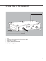
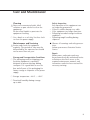
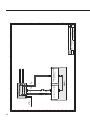
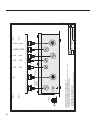
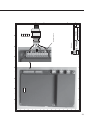
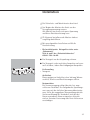
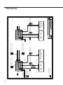
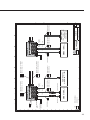
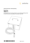
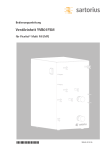
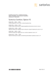
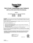
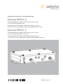
Installation Instructions | Betriebsanleitung
Sartorius YPSC01-X
Configurable power supply and communication system
for use inside hazardous areas
Konfigurierbares Netzgerät und Kommunikationssystem
für den Einsatz innerhalb des explosionsgefährdeten Bereichs
Sartorius YPSC01-Z
Configurable power supply and communication system
for use outside hazardous areas, only
Konfigurierbares Netzgerät und Kommunikationssystem
nur für den Einsatz außerhalb des explosionsgefährdeten Bereichs
98647-004-37
English – page 3
Deutsch – Seite 33
Français – page 33
Italiano – pagina 48
Español – página 63
2
General View of the Equipment
1
6
2
5
4
3
1
2
3
4
5
6
Cover
Connecting cable (intrinsically safe) for power supply
Power cord (110/240 V)
Terminal (equipotential bonding)
Bracket for mounting
Manufacturer’s ID label
3
Contents
Intended Use
General View of the Equipment
3
Intended Use
4
Warnings and Safety Precautions
5
Installation
7
Care and Maintenance
9
Disposal
10
Specifications
11
Accessories
11
Dimensions
12
EC Declaration of Conformity
14
EC Type-Examination Certificate
(KEMA)
15
Documents
18
The following symbols are used in
these instructions:
§ indicates required steps
$ indicates steps required only under
certain conditions
> describes what happens after you have
performed a particular step
– indicates an item in a list
! indicates a hazard
4
The YPSC01 power supply must be
connected to a 100-240 VAC/50/60 Hz
power source.
It supplies intrinsically safe electric
circuits for supply of up to two intrinsically safe Sartorius devices (scales,
indicators). A non-intrinsically safe
4...20 mA or Profibus-DP interface can
also be optionally installed.
Note:
See drawings under “Documents”.
Read the warnings and safety precautions carefully before the power supply
is connected and put into operation.
Warnings and
Safety Precautions
–
–
–
–
The area of application of the power
supplies is defined in the attached
documents (see “Documents”). All limitations mentioned in these documents
must be complied with. Operation that
does not comply with these limitations
is not permitted and is deemed as unintended use. Incorrect installation and
unintended use will result in forfeiture
of all claims under the manufacturer’s
warranty and may also result in the
expiration of the validity of the
authorization.
Work on the device should only be
carried out by technicians trained and
authorized by Sartorius.
Incorrect use can lead to injury to
persons and damage to property.
The power supply must only be installed
and operated by a qualified technician.
The relevant national laws, standards
and regulations (in particular concerning accident prevention and environmental protection) of the respective
country must be followed. Ask your
supplier for information on the legal
regulations applicable in your country.
Installation must be carried out by
a qualified electrician. A qualified electrician is deemed to be a person who is
familiar with the assembly, start-up and
operation of the equipment. The qualified electrician has the appropriate
qualifications and they are familiar with
the relevant conditions and regulations.
If necessary, speak to the supplier or
Sartorius Service Center.
The safety instructions in accordance
with drawing 65801-751-16-A4 (see
“Documents”) must be observed.
These instructions should be understandable to all those concerned and
the documents must always be to hand.
All warnings and safety precautions
in the documents of the connected
electrical equipment (and accessories)
must also be followed. The operator
must add to these warnings and safety
precautions if necessary and brief the
operators accordingly. Always keep the
equipment freely accessible.
– The power supplies comply with the
requirements of Directive 94/9/EC for
use in hazardous areas. The power
supply YPSC01-X may be installed in
hazardous areas (Zones 1 and 2 (gases)
and Zones 20, 21 and 22 (dusts)).
Note:
The power supply YPSC01-Z must only
be installed outside of the hazardous
area.
– When used in a hazardous area in
which compatible dusts are present,
clean the power supply regularly to
prevent excessive build-up of dust.
The maximum permissible dust layer
thickness is 5 mm.
– The IP protection in accordance with
DIN EN 60529 (IP65) must be intact for
use in hazardous areas. For this reason,
it is essential that the installation and
maintenance are performed with
extreme care:
– Make sure all seals are installed
(in particular those under the
6 screws for securing the cover)
– Observe all instructions carefully
when installing the cover
– Tighten the fastening screws
– Tighten the cable glands and make
sure they are installed in accordance
with instructions
5
– There is a connecting bolt on the
housing. The position is marked with a
grounding symbol. Use this to connect
the power supply to the equipotential
bonding conductor (PA). Disconnecting
the equipotential bonding cables is not
permitted. The grounding cable must
have a minimum cross-section of
4 mm2. Connect all equipment and
accessory parts to the equipotential
bonding conductor.
– The power supply may only be operated
within an ambient temperature range
of –20°C to +4°C (–4° to +104°F).
–
–
–
! Always disconnect the power supply
from the mains (in the case of YPSC01-Z,
disconnect the power plug) before
opening the power supply, before
connecting or disconnecting cables or
before connecting electronic attachments to the data interface.
– The power supplies also comply with
the requirements of the EC directives
for electromagnetic compatibility and
electrical safety in conjunction with
the connectable Sartorius equipment
(scales/indicators). For the EC Declaration of Conformity relating to the EMC,
refer to the EC Declaration of Conformity
in the supplied documents of the
connectable Sartorius equipment
concerned.
– Do not expose the power supply to
aggressive chemical vapors or to unnecessarily extreme temperatures, moisture,
shocks, or vibration. The casing on all
connecting cables as well as the casing
on the wires of the internal cabling is
made of PVC or of rubber. The PCBs are
encapsulated using Elastosil RT607
silicone rubber. Chemicals (e.g. gases
or liquids) which can internally or externally attack and damage the equipment,
6
–
–
–
–
encapsulating material or cables must
be kept away from the power supply.
It is essential that the equipment is well
ventilated in order to avoid heat
build-up.
Exposure to excessive electromagnetic
interference can cause the readout value
of the connectable Sartorius equipment
to change. After the end of this interference, the device can be used for its
designated purpose again.
Pay attention to the pin assignments
when using externally procured cable.
Check the connections of the cable
against the corresponding cabling diagram before connecting to the Sartorius
equipment and disconnect any wires
that are assigned differently. The operator shall be solely responsible when
using cables not supplied by Sartorius.
The power connection must be made in
accordance with the regulations applicable in your country. If necessary, speak to
the supplier or Sartorius Service Center.
Any installation work that does not conform to the instructions in this manual
results in forfeiture of all claims under
the manufacturer’s warranty.
Only use original replacement parts.
Always make sure the equipment is
disconnected from AC power before
performing any maintenance, cleaning
or repair work.
If there is any indication that safe
operation of the equipment is no longer
guaranteed, disconnect the equipment
from the power and ensure that it is not
used further (e.g. if there is damage).
Installation
! Observe all warnings and safety precautions.
! Always disconnect the power supply before begin-
ning any work on the equipment.
Never perform any work on the equipment while it is
energized. Read the installation instructions.
! Work that affects the IP protection must be carried
out with extreme care.
! Any installation work that does not conform to the
instructions in this manual results in forfeiture of all
claims under the manufacturer’s warranty.
– See “Documents” for the installation of the
power supply
Pages 6 and 7 of the “Safety Instructions”
65801-751-16-A4.
§ Remove the power supply from the packaging.
§ After unpacking the power supply, inspect the
device immediately for any visible external damage.
Equipment Supplied
– Power supply
Installation Location
Choose a suitable location where the power supply
will not be exposed to drafts, heat radiation, moisture or vibrations.
Connecting to Power Supply
Power is supplied via the permanently connected
power cord. Make sure that the voltage rating printed on this unit is identical to your local line voltage.
If the stated supply voltage or the plug design of the
power cord does not comply with the standard you
use, please inform your nearest Sartorius representative or your supplier.
7
YPSC01-X Installation
In order to connect the equipment to the power
supply, use a correctly installed ATEX-certified
connector with a protective grounding conductor
(PE). The supply line should be protected with
a maximum 16 A fuse.
! Observe all warnings and safety precautions.
See also: “Safety Instructions” documents.
YPSC01-Z Installation
In order to connect the equipment to the power
supply, use a correctly installed wall outlet with
a protective grounding conductor (PE) and a fuse
of a maximum 16 A.
§ The power supply must only be connected outside
of the hazardous area.
§ Plug the power cord into the wall outlet (mains).
! Observe all warnings and safety precautions.
See also: “Safety Instructions” documents.
Note:
When installing the equipment in a hazardous area,
plug connectors may only be connected or disconnected when there is no current and the power
supply has been switched off.
Before connecting attachments (printer, PC) to the
data interface of the equipment, the equipment
must be disconnected from the mains.
8
Care and Maintenance
Cleaning
! Never use concentrated acids, alkali
solutions or pure alcohol to clean the
equipment.
Do not allow liquids to penetrate the
equipment housing.
$ Use a brush or a soft, dry, lint-free cloth
to clean the power supply.
Maintenance and Servicing
! Service and check the equipment
regularly. The periods of time must be
determined by the operator, but should
not be more than one year.
Storage and Transportation Conditions
$ The packaging used for shipping your
Sartorius equipment is optimally
designed to prevent damage during
transport. It is a good idea to save the
box and all parts of the packaging for
future storage or shipment of the power
supply.
–
–
–
–
Safety Inspection
Safe operation of the equipment can
no longer be guaranteed:
If there is visible damage to a cable
If the equipment no longer functions
Following extended storage in adverse
conditions
Following rough handling during
shipment
§ Observe all warnings and safety precautions.
Inform your nearest Sartorius Service
Center.
Repair
Maintenance and repair work may
be performed only by authorized service
technicians who have access to the
required maintenance manuals and
instructions and who have received the
necessary training.
$ Storage temperature: –20°C ... +70°C
$ Permitted humidity during storage:
up to 80%
9
Disposal
In Germany and many other countries
(see www.sartorius.com
Service Download area for details)
Sartorius AG or the organization
contracted by us takes care of the
return and legally compliant disposal of
its electrical and electronic equipment
on its own. In countries that are not
members of the European Economic
Area (EEA) or where no Sartorius
subsidiaries or dealerships are located,
please contact your local authorities or
a commercial disposal operator.
These products may not be placed
with household waste or brought to
collection centers run by local public
disposal operations – not even by small
commercial operators.
For disposal in Germany and in the
other member states of the European
Economic Area (EEA), please contact
our service technicians on location
at our Service Center in Göttingen,
Germany:
Sartorius AG
Service Center
Weender Landstrasse 94–108
37075 Göttingen, Germany
10
Sartorius AG, its affiliates, subsidiaries,
dealers and distributors will not take
back equipment contaminated with
hazardous materials (ABC contamination) – either for repair or disposal.
Please refer to the accompanying
leaflet/manual or visit our internet
website (www.sartorius.com) for comprehensive information that includes
our service addresses to contact if you
plan to send your equipment in for
repairs or proper disposal.
If you no longer need the packaging
after successful installation of the
equipment, you should return it for
recycling. The packaging is made from
environmentally friendly materials and
is a valuable source of secondary raw
material.
The equipment, including
accessories and batteries
does not belong in your
regular household waste.
Specifications
EX- approval
Connection:
Power consumption:
Storage temperature:
Operating temperature range:
Ambient conditions:
Highest relative humidity:
IP protection:
Housing:
Standard cable lengths:
Dimensions:
Weight:
KEMA 08 ATEX 0044
100 – 240 VAC (50/60 Hz, -10% ... +10%)
40 ... 80 VA (depending on the number of PCBs installed)
–20°C to +70°C
–20°C to +40°C
Height of up to 2,000 m
80% for temperatures up to 31°C,
decreasing linearly to 50% relative humidity at 40°C
IP65 in accordance with EN 60529
Stainless steel housing
Power cord: 3 m
(with intrinsically safe DC power cable: 3 m)
see dimension drawing
approx. 4 kg (without cable)
Accessories
Equipment for mounting rail assembly
11
Dimensions
8 mm
(4+)
18
75
125
180
186
12
300
285
270
276
Deckel
Cover
15
25
75
120
150
170
200
230
270.0
Deckel
Cover
0. 55
0.25
90
13
4
3
14
EC Type-Examination Certificate (KEMA)
15
16
17
18
A
B
C
D
E
F
G
H
N1
200m
8
Maximum cable length
Option number
7
6
4
N12 65801-057-00 (x m)
N11 65801-007-00 (3 m)
5
4
65607-339-00 (x m)
N20 65607-353-00 (1 St) (Termination)
N19 65607-351-00 (x m) (Profibus-DP)
Profibus-DP
4...20mA or Profibus-DP
N17 65607-341-00 (x m) (4 ... 20 mA)
N18 65607-351-00 (x m) (Profibus-DP)
5
Digital Weighing
Platform IS......-.X...
65607-510-00 (0,2 m)
65801-007-00 (3 m)
65801-057-00 (x m)
N2
40m
1000m
N1
40m
CIXS3 / CX3..-...
65607-337-00 (0,2 m)
N7
65801-036-00 (USA)
DC
Supply
Data
200m
Mainboard 1
Mainboard 2
4...20mA or
Profibus-DP Module
DC
Supply
7-65607-340-00 (4 ... 20 mA)
1000m
7-65607-350-00 (Profibus-DP)
A4
6
B1
7
YPSC01-X
65801-006-00 (EG)
65607-338-00 (x m)
N10
N9
Power
100 - 240 Vac
7-65801-120-00
L10
8
N4
N3
25m
DC
Supply
08.07.08
3
Klausgrete
YPSC01-X
25m
DC
Supply
2
N13 65801-017-00 (3 m)
1
65801-751-05-A3
Options
(without 4...20mA and
Profibus-DP)
2
1
8
1
Rev.
00
of
Page
N14 65801-067-00 (x m)
CIXS3 / CX3..-...
65801-067-00 (x m)
65801-017-00 (3 m)
CIXS3 / CX3..-...
N8
200m
Data
Mainboard 1
Mainboard 2
4...20mA or
Profibus-DP Module
YPSC01-X
3
A
B
C
D
E
F
G
H
Documents
19
A
B
C
D
E
F
G
H
N1
200m
8
N7
65801-057-00 (x m)
Option number
Maximum cable length
7
CIXS3 / CX3..-...
6
4
N12 65801-057-00 (x m)
N15 65801-027-00 (20 m)
5
4
65607-339-00 (x m)
N20 65607-353-00 (1 St) (Termination)
N19 65607-351-00 (x m) (Profibus-DP)
Profibus-DP
4...20mA or Profibus-DP
N17 65607-341-00 (x m) (4 ... 20 mA)
N18 65607-351-00 (x m) (Profibus-DP)
5
Digital Weighing
Platform IS......-.X...
65607-510-00 (0,2 m)
65801-027-00 (20 m)
N2
40m
1000m
N5
DC
Supply
40m
Data
200m
Mainboard 1
Mainboard 2
4...20mA or
Profibus-DP Module
DC
Supply
7-65607-340-00 (4 ... 20 mA)
1000m
7-65607-350-00 (Profibus-DP)
B1
6
A4
7
YPSC01-Z
65607-337-00 (0,2 m)
65607-338-00 (x m)
Power
100 - 240 Vac
57004-592-01
(Red.)
7-65801-120-00
L10
8
N4
N6
25m
DC
Supply
3
Klausgrete
08.07.08
YPSC01-Z
25m
DC
Supply
2
N16 65801-037-00 (20 m)
1
65801-751-05-A3
Options
(without 4...20mA and
Profibus-DP)
2
1
8
2
Rev.
00
of
Page
N14 65801-067-00 (x m)
CIXS3 / CX3..-...
65801-067-00 (x m)
65801-037-00 (20 m)
CIXS3 / CX3..-...
N8
200m
Data
Mainboard 1
Mainboard 2
4...20mA or
Profibus-DP Module
YPSC01-Z
3
A
B
C
D
E
F
G
H
20
DC
Supply
4
4
08.07.08
3
CHX3..-......-...
2
2
Options
1
Page
3
F
G
H
A
B
C
7
6
5
Digital Weighing Platform
of the CHX3.-...
CHX3.-...
Indicator of the CHX3.-...
3
Klausgrete
1
65801-751-05-A3
8
Rev.
00
of
A
B
C
D
DC
Supply
Profibus-DP
4...20mA or Profibus-DP
5
D
Data
6
E
8
Power
100 - 240 Vac
Mainboard 1
Mainboard 2
4...20mA or
Profibus-DP Module
YPSC01-.
7
E
F
G
H
8
21
65801-057-00 (x m)
N2
N5
FC/FCA/IS......-.X...
65801-057-00 (x m)
65801-027-00 (20 m)
DC Supply
25m / 40m
Mainboard 1
FC/FCA/IS......-.X...
Options
N12 65801-057-00 (x m)
N15 65801-027-00 (20 m)
YPSC01-Z:
N12 65801-057-00 (x m)
N11 65801-007-00 (3 m)
YPSC01-X:
25m / 40m
DC Supply
2
1
Page
4
D
E
F
G
H
A
7
4
3
Klausgrete
08.07.08
FC/FCA/IS......-.X...
2
1
65801-751-05-A3
8
Rev.
00
of
A
B
5
N2
YPSC01-Z:
65801-057-00 (x m)
N1
3
Mainboard 2
YPSC01-.
YPSC01-X:
Power
100 - 240 Vac
L10
65801-007-00 (3 m)
7-65801-120-00
4
B
6
65801-027-00 (20 m)
N5
N2
5
C
8
65801-057-00 (x m)
N2
YPSC01-Z:
65801-007-00 (3 m)
6
N1
YPSC01-X:
25m / 40m
DC Supply
FC/FCA/IS......-.X...
Power
100 - 240 Vac
Mainboard 1
YPSC01-.
7
C
D
E
F
G
H
8
22
1)
2)
3)
4)
5)
***
mains connection
for additional
equipment
100 - 240 Vac
N9
N10
**
mains connection
100 - 240 Vac
5
#
N19
N20
#
N19
N20
5)
**
4
#
N17
N18
#
N17
N18
4
4)
#
N7
N8
#
N7
N8
3)
08.07.08
#
N11
N12
N13
N14
#
N15
N12
N16
N14
3
2)
N5
N2
N6
N4
N1
N2
N3
N4
1)
2
2
(default)
(default)
Options
1
Page
5
F
G
H
A
8
7
6
*: Use ATEX certified Ex e - cable glands type M20 x 1,5, only!
**: Use ATEX certified Ex e - cable glands type M16 x 1,5, only!
***: Mains cable (e.g. H05RN-F3x1,5²) of additional equipment (e.g. base station of a barcode scanner)
5
3
Klausgrete
1
65801-751-05-A3
8
Rev.
00
of
A
B
B
intrinsically safe DC supply to device no. 1 (e. g. CIXS3 or FC/FCA/IS......-.X.)
intrinsically safe DC supply to device no. 2 (e. g. CIXS3 or FC/FCA/IS......-.X.)
intrinsically safe connection cable (from the built-in data output board to the UNICOM board in the CIXS3, CX3..-... or CHX3.-...
non-intrinsically safe data cable for data output 4...20mA or Profibus-DP (input)
non-intrinsically safe data cable for data ou tput Profibus- DP (output or termination)
C
C
External Connections
D
*
6
D
7
E
equipotential
bonding
YPSC01-Z:
YPSC01-X:
E
F
G
H
8
23
6
5
4
4
N11
3
4
6.
8
9.
1
2
Option number
N11
N12
N13
N14
Marking with number
2
1
Page
6
D
E
F
G
H
A
3
Klausgrete
08.07.08
2
Option L10: 2 nd Mainboard
1
65801-751-05-A3
Options
8
Rev.
00
of
A
B
7
5
B
L10
6
C
8
7
C
D
E
F
G
H
8
6
5
16V (red)
4
4
N17
N17
3
Option number
2
2
Options
1
Page
7
D
E
F
G
H
A
08.07.08
3
Klausgrete
Option A4 (4 ... 20mA)
1
65801-751-05-A3
8
Rev.
00
of
A
B
7
GND (black)
brown
white
green + yellow
plug on
connector
N8
N7
5
B
8
Iout
Iin (GND)
Vout
Vin (GND)
Screen
Screen
6
C
A4
(65607-340-00)
4...20 mA
A4
7
C
D
E
F
G
H
8
LV2
LV1
ST1
1 2 3 4 5 6
2
1
24
25
6
4
N18
Option number
Data B_BUS
Data A_BUS
Data A_BUS
GND_BUS
Data B_BUS
+5V_BUS
LV3
GND
+5V
GND
RxD
TxD
N7
Options
green
red
black
brown
RS232
monitor
(for
service
only)
plug on
connector
N8
N18
N20
1
Page
8
D
E
F
G
H
A
7
5
16V (red)
GND (black)
3
Klausgrete
08.07.08
2
Option B1 (Profibus-DP)
1
65801-751-05-A3
8
Rev.
00
of
A
B
8
N18
green: Data A
red: Data B
(65607-350-00)
Profibus-DP
B1
2
B
RS232
monitor
(for
service
only)
plug on
connector
N19
3
C
B1
Data B_BUS
Data A_BUS
Data A_BUS
GND_BUS
Data B_BUS
+5V_BUS
LV3
GND
+5V
GND
RxD
TxD
N7
N8
4
red
C
D
E
F
(65607-350-00)
Profibus-DP
B1
1
G
LV2
LV1
5
red
red
6
1
7
green
green
ST1
1 2 3 4 5 6
2
1
LV2
LV1
ST1
1 2 3 4 5 6
2
1
H
8
green
1
3
2
Power supply
YPSC01-X
8
4
Power supply
YPSC01-Z
(for installation outside of the
hazardous area only)
5
6
9
7
10
FCA......-.X... (EEx i - Terminal)
9
11
13
14
13
FCA......-.X...(EEx i - Weighing platform)
9
12
Hazardous area
Zone 1 and 2
Name
Erstellt
Writt en by
24.04.08
Klausgrete
Geprüft
Reviewed by
24.04.08
Klausgrete
Freigabe
Released by
26
Materials
Datum
Date
24.04.08
Klausgrete
YPSC01-X, YPSC01-Z
Benennung / Title
Safety Instructions
Ausgabe / Revision
00
Änderung / Alteration
---
Zeichnungs-Nr. / Drawing nu mber
65801-751-16-A4
Maßstab /
Scale
---
Blatt
Sheet
1
von
of
7
1
3
2
Power supply
YPSC01-X
8
4
Power supply
YPSC01-Z
(for installation outside of the
hazardous area only)
5
6
13
14
13
7
12
FC......-.X... (EEx i - Weighing platform)
9
11
FC......-.X... (Display unit)
Hazardous area
Zone 1 and 2
Materials
Datum
Date
Name
Erstellt
Writt en by
24.04.08
Klausgrete
Geprüft
Reviewed by
24.04.08
Klausgrete
Freigabe
Released by
24.04.08
Klausgrete
YPSC01-X, YPSC01-Z
Benennung / Title
Safety Instructions
Ausgabe / Revision
00
Änderung / Alteration
---
Zeichnungs-Nr. / Drawing nu mber
65801-751-16-A4
Maßstab /
Scale
---
Blatt
Sheet
2
von
of
7
27
1
3
2
Power supply
YPSC01-X
8
4
Power supply
YPSC01-Z
(for installation outside of the
hazardous area only)
5
6
13
14
7
13
IS......-.X... (EEx i - Weighing platform)
9
12
Hazardous area
Zone 1, 2, 20, 21 and 22
(if the weighing platform is approved for Zone 2.)
Name
Erstellt
Writt en by
24.04.08
Klausgrete
Geprüft
Reviewed by
24.04.08
Klausgrete
Freigabe
Released by
28
Materials
Datum
Date
24.04.08
Klausgrete
YPSC01-X, YPSC01-Z
Benennung / Title
Safety Instructions
Ausgabe / Revision
00
Änderung / Alteration
---
Zeichnungs-Nr. / Drawing nu mber
65801-751-16-A4
Maßstab /
Scale
---
Blatt
Sheet
3
von
of
7
1
3
2
Power supply
YPSC01-X
4
8
Power supply
YPSC01-Z
(for installation outside of the
hazardous area only)
4
22
21
5
6
7
20
9
Complete scales
CX3S.-...
10
EEx i - Indicator CIXS3
9
13
14
13
12
11
EEx i - Analog platform
CAPX..-......-......
9
EEx i - Equipment
(see sheets 1 - 3)
Materials
Datum
Date
Name
Erstellt
Writt en by
24.04.08
Klausgrete
Geprüft
Reviewed by
24.04.08
Klausgrete
Freigabe
Released by
24.04.08
Klausgrete
Hazardous area
Zone 1, 2, 20, 21 and 22
YPSC01-X, YPSC01-Z
Benennung / Title
Safety Instructions
Ausgabe / Revision
00
Änderung / Alteration
---
Zeichnungs-Nr. / Drawing nu mber
65801-751-16-A4
Maßstab /
Scale
---
Blatt
Sheet
4
von
of
7
29
1
3
2
Power supply
YPSC01-X
4
Power supply
YPSC01-Z
(for installation outside of the
hazardous area only)
4
22
21
5
6
7
8
20
9
9
Complete scales
CHX3.-…
10
EEx i - Indicator CIXS3
9
13
14
13
12
EEx i - Digital platform
IS.....-.X...
Hazardous area
Zone 1, 2, 20, 21 and 22
(if the weighing platform is approved for Zone 2)
Name
Erstellt
Writt en by
24.04.08
Klausgrete
Geprüft
Reviewed by
24.04.08
Klausgrete
Freigabe
Released by
30
Materials
Datum
Date
24.04.08
Klausgrete
YPSC01-X, YPSC01-Z
Benennung / Title
Safety Instructions
Ausgabe / Revision
00
Änderung / Alteration
---
Zeichnungs-Nr. / Drawing nu mber
65801-751-16-A4
Maßstab /
Scale
---
Blatt
Sheet
5
von
of
7
These safety instructions apply for the installation, operation, maintenance and repair of the equipment
The numbers in brackets correspond to the item numbers on the previous sheets.
1.
Installation should be performed by an authorized specialist, in accorda nce with applicable laws, rules and
regulations, ordinances and standards. Particular attention should be paid to the European Standards 6007914 (for potentially explosive gas atmospheres) and EN 61241-14 (for use in the presence of combustible
dust).
2.
It is essential that the recommendations on the installation, use, maintenan ce and repair contained in the
manuals supplied are complied with for all equipment.
3.
The power supply (1) type YPSC01-X is suitable for use in potentially explosive atmospheres (Zones 1, 2, 20,
21 and 22). The power supply (1) type YPSC01-Z must be installed outside of the potentially explosive
atmosphere.
4.
Install the power supply (1) so that heat can be sufficiently dissipated on all s ides and so that external heat
sources are located far enough away from the power supply. Protect th e non-intrinsically safe mains
connecting cable (2) from damage and connect it correctly to the mains powe r supply (100 - 240 VAC). The
power supply is approved for circuits up to 1,500 A. Only use the mains connecting cable in the hazardous
area with a suitable and approved explosion-protected plug or attach it directl y. Be sure to provide a suitable
emergency shutoff switch.
5.
The mains connecting cable (2), the intrinsically safe power cable (8) and c onnecting cable (20) are suitable
for flexible installation. The corresponding cable glands (3) and (4) are only suitable for fixed installation when
using the power supply (1) in potentially explosive atmospheres, meaning that the equipment installer has to
fit the cable behind the cable gland (e.g. using a cable clip). These cab le glands can be replaced by those
which are ATEX certified and are suitable for flexibly installed cable.
6.
Intrinsically safe cable (blue stranded) cannot be openly used in hazardous areas in which combustible dusts
are present as dust can penetrate the contacts. Seal unused intrinsically safe cable with a suitable protective
cap. As a general rule, non-intrinsically safe cable may not be used unsealed in potentially explosive
atmospheres.
7.
When installing a data interface (e.g. "Profibus-DB" or "4...20 mA") in the power supply (1), the lines that
are non-intrinsically safe (21) lead the signals out of the power supply. These lines are only suitable for fixed
installation. The corresponding cable glands (22) are only suitable for fixed installation when using the power
supply (1) in potentially explosive atmospheres, meaning that the equipment installer has to fit the cable
behind the cable gland, even if a cable is used f or flexible installation.
8.
Using a copper wire (6) with a gauge of at least 4mm², wire the housing to the equipotential busbar (7) via the
terminal (5) on the power supply.
9.
Intrinsically safe equipment does not have to be connected to the equi potential busbar (7) using the
equipotential bonding terminals (10) and (12) if the shields (screens) in the intrinsically safe power supply
cables (8) and (11) have and maintain a sufficiently low resistance so tha t no dangerous increase in the
potential can occur for the compensating currents to be expected. Otherwi se this equipment must be
connected to the equipotential bonding conductor (PA). This is recommended for cables longer than 10 m.
10. Metal parts must be grounded (earthed) so that electrostatic charges can be conducted away from the
equipment. The weighing pan/load plate (14) can rest on pads (13) with a hig h ohm rating, provided that their
resistance values are much lower than the maximum permissible limit of 1 GOhm. If electrostatic charges
cannot be conducted fast enough away from the equipment in processes such as fast filling, then the
operator must additionally ground (earth) the weighing pan/load cell. Caution: this grounding connection may
alter the metrological or electromagnetic perfor mance of the equipment.
11. The power supply (1) is, amongst other things, designed in compliance with ignition protection class "m"
(encapsulation) and has been encapsulated accordingly. Chemicals that at tack silicon and rubber must
therefore be kept away from t he power supply.
Materials
Datum
Date
Name
Erstellt
Writt en by
24.04.08
Klausgrete
Geprüft
Reviewed by
24.04.08
Klausgrete
Freigabe
Released by
24.04.08
Klausgrete
YPSC01-X, YPSC01-Z
Benennung / Title
Safety Instructions
Ausgabe / Revision
00
Änderung / Alteration
---
Zeichnungs-Nr. / Drawing nu mber
65801-751-16-A4
Maßstab /
Scale
---
Blatt
Sheet
6
von
of
7
31
12.
13.
14.
15.
16.
17.
18.
19.
20.
21.
22.
23.
24.
25.
26.
27.
Materials
Datum
Date
Name
Erstellt
Writt en by
24.04.08
Klausgrete
Geprüft
Reviewed by
24.04.08
Klausgrete
Freigabe
Released by
32
Make sure that there is sufficient cooling of the equipment. Avoid hea t build-up. Keep the equipment away
from exposure to heat sources and direct sunlight. If the equipment is installed in a housing, be sure that it
is positioned at the proper distance from the other components installed and take measures to ensure that
heat is properly dissipated.
If the equipment does not operate properly, unplug it from the line po wer (mains supply) immediately.
Please observe the "Installation and Safety Instructions" given in the documents supplied. These
documents also provide information on the chemical resistances of the products.
The special conditions given in the EC Type Examination Certificates (original copy in the documents
supplied) must be observed. These include the permissible ambient temperature range, gas group and
temperature class. In addition, the certificates provide instructions and information on use of the equipment
in hazardous areas with potentially explosive dust atmospheres.
Only open non-intrinsically safe equipment with the power on outside of hazardous areas with potentially
explosive dust atmospheres. Avoid opening intrinsically safe equipment while the power is on within a
hazardous area, whenever possible.
All metal parts (housing, support arm, load plate, drive-on ramp, bench, etc.) must be electrically connected
to the terminal for the equipotential bonding conductor (PA) so that any electrostatic charges can be
conducted away from the equipment. For this purpose, the equipment operator is obligated to connect a
lead with a gauge of at least 4 mm² (cross section) to the equipotential bonding terminal (PA) located on the
side of the housing. The low resistance of this connection to the PA busbar must be checked when the
system is installed at the intended place of use.
Avoid generating static electricity. Only use a damp cloth to clean the equipment. The equipment operator
shall be responsible for preventing any risks caused by static electricity.
Keep chemicals which can attack the housing seals and cable sheaths away from the equipment. These
include oil, grease, benzene, acetone and ozone. If you are not sure about a certain substance, please
contact the manufacturer. It is not permitted to expose the equipment to UV radiation.
Only use equipment in the temperature ranges indicated. Avoid exposing the equipment to heat.
At reasonable intervals, have your equipment checked for proper functioning and safety by a trained and
certified technician.
If your equipment needs to be repaired, only use original replacement parts supplied by the manufacturer.
Any tampering with the equipment by anyone other than authorized Sartorius service technicians will result
in the loss of Ex conformity for Zone 2 and in the forfeiture of all claims und er the manufacturer's warranty.
Only authorized specialists may open the equipment.
Modifications, including those to be carried out by Sartorius employees, are only permitted with express
written authorization.
Seals and gaskets must be regularly inspected (particularly after the equipment housing has been opened)
for damage (cracking), buildup of dirt, brittleness and any further cha nges that adversely affect IP
protection. The equipment must be closed so that the IP protection is restored to the rating originally
specified. Replace defective seals and gaskets.
Dust layers (deposits on the housing) may not exceed a thickness of 5 mm on equipment approved for use
in Zones 20, 21 or 22. In order to avoid heat build-up, the maximum dust layer should remain below this
level. Note: The equipment operator can determine the temperature themselves in accordance with EN
61241-14 with a layer thickness of up to 50 mm.
These instructions are given in addition to those in the instruction manuals and do not release the operator
from his responsibilities for the installation, operation and inspection of the equipment assembly in
compliance with the valid standards, directives, ordinances and laws.
24.04.08
Klausgrete
YPSC01-X, YPSC01-Z
Benennung / Title
Safety Instructions
Ausgabe / Revision
00
Änderung / Alteration
---
Zeichnungs-Nr. / Drawing nu mber
65801-751-16-A4
Maßstab /
Scale
---
Blatt
Sheet
7
von
of
7
Übersichtsdarstellung
1
6
2
5
4
3
1
2
3
4
5
6
Deckel
Anschlusskabel (eigensicher) zur Spannungsversorgung
Netzanschluss (110/240 V)
Erdung (Potenzialausgleich)
Winkel zur Befestigung
Typenschild
33
Inhalt
Verwendungszweck
Übersichtsdarstellung
33
Verwendungszweck
34
Warn- und Sicherheitshinweise
35
Installation
37
Pflege und Wartung
39
Entsorgung
40
Technische Daten
41
Zubehör
41
Maßzeichnungen
42
EG-Konformitätserklärung
44
EG-Baumeisterprüfbescheinigung
45
Dokumente
48
Folgende Symbole werden in dieser
Anleitung verwendet:
§ steht vor Handlungsanweisungen
$ steht vor Handlungsanweisungen, die
nur unter bestimmten Voraussetzungen
ausgeführt werden sollen
> beschreibt das, was nach einer
ausgeführten Handlung geschieht
– steht vor einem Aufzählungspunkt
! weist auf eine Gefahr hin
34
Das Netzgerät YPSC01-. wird an
eine Versorgungsspannung von
100–240 Vac / 50/60 Hz angeschlossen.
Es liefert eigensichere Stromkreise zur
Versorgung von bis zu zwei eigensicheren Sartorius-Betriebsmitteln (Waagen,
Indikatoren). Optional kann auch eine
nicht eigensichere „4...20 mA“- oder
„Profibus-DP“- Schnittstelle eingebaut
werden.
Hinweis:
Siehe Zeichnungen unter „Dokumente“.
Bevor das Netzgerät angeschlossen und
in Betrieb genommen wird, die Sicherheits- und Warnhinweise aufmerksam
durchlesen!
Sicherheits- und Warnhinweise
–
-
-
-
Der Einsatzbereich der Netzgeräte ist
in den beigefügten Dokumenten (siehe
unter Dokumente) definiert. Alle darin
genannten Beschränkungen sind einzuhalten. Ein Betrieb über diese Beschränkungen hinaus ist nicht zulässig und
gilt als nicht bestimmungsgemäßer
Gebrauch. Bei unsachgemäßer Installation und unsachgemäßem Gebrauch
entfällt die Gewährleistung. Ggf. erlischt
auch die Gültigkeit der Zulassung.
Ein Eingriff in das Gerät sollte nur
durch von Sartorius geschultes und
autorisiertes Personal erfolgen.
Ein unsachgemäßer Gebrauch kann zu
Schäden an Personen und Sachen führen. Das Netzgerät nur von qualifiziertem Personal installieren und betreiben.
Relevante nationale Gesetze, Normen
und Vorschriften (insbesondere zur
Unfallverhütung und zum Umweltschutz) des jeweiligen Landes befolgen.
Den Lieferanten nach den in Ihrem Land
geltenden Bestimmungen befragen.
Die Installation muss von einer Elektrofachkraft erfolgen. Als Elektrofachkraft
gilt eine Person, die mit der Montage,
Inbetriebnahme und Betrieb der Anlage
vertraut ist. Die Elektrofachkraft verfügt
über die entsprechende Qualifikation,
die einschlägigen Bestimmungen und
Vorschriften sind Ihr bekannt.
Bei Bedarf den Händler oder SartoriusKundendienst ansprechen.
Die Sicherheitshinweise gemäß Zeichnung 65801-750-16-A4 (siehe unter
Dokumente) sind unbedingt zu
beachten!
Diese Hinweise sollten alle Beteiligten
verstehen und die Dokumente stets
griffbereit sein. Auch die Sicherheitsund Warnhinweise in den Unterlagen
der angeschlossenen elektrischen
Betriebsmittel (auch Zubehör) befolgen.
Diese Sicherheits- und Warnhinweise
muss der Betreiber ggf. ergänzen. Das
Bedienpersonal entsprechend einweisen.
Die Einrichtungen immer frei zugänglich halten!
– Die Netzgeräte erfüllen die Anforderungen der Richtlinie 94/9/EG für den Einsatz in explosionsgefährdeten Bereichen. Das Netzgerät YPSC01-X darf in
Gasexplosionsgefährdeten Bereichen der
Zone 1 und 2 sowie in Staubexplosionsgefährdeten Bereichen der
Zone 20, 21 und 22 installiert werden.
Hinweis:
Das Netzgerät YPSC01-Z darf nur
außerhalb des explosionsgefährdeten
Bereichs installiert werden.
– Bei Verwendung in Staubexplosionsgefährdeten Bereichen das Netzgerät
regelmäßig von Staub zu befreien.
Es ist nur eine maximale Staubschichtdicke von 5 mm zulässig.
– Für den Einsatz im explosionsgefährdeten
Bereich muss der IP-Schutz gemäß
DIN EN 60529 (IP65) sichergestellt sein.
Die Installation und Wartung erfordert
deshalb besondere Aufmerksamkeit:
– Alle Dichtungen einsetzen (insbesondere die unter den 6 Schrauben zur
Befestigung des Deckels)
– Deckel vorschriftsmäßig montieren
– die Schrauben fest anziehen
– Kabelverschraubungen fest anziehen
und vorschriftsmäßig montieren
35
– An dem Gehäuse befindet sich ein Anschlussbolzen. Die Stelle ist mit einem
Erdungssymbol gekennzeichnet. Über
diesen das Netzgerät an den Potenzialausgleich (PA) anschließen. Eine Unterbrechung der Potenzialausgleichsleitungen ist untersagt. Das Erdungskabel muss
einen Mindestquerschnitt von 4 mm2
haben. Alle Geräte und Zubehörteile mit
dem Potentialausgleich verbinden.
– Das Gerät nur in einer Umgebungstemperatur von -20° C bis +40°C betreiben.
! Vor jedem Öffnen des Netzgeräts, vor
Anschluss oder Trennen von Kabeln oder
vor Anschluss von elektronischen
Zusatzgeräten an die Datenschnittstelle
das Netzgerät vom Netz trennen (bei
YPSC01-Z Netzstecker ziehen).
– Die Netzgeräte erfüllen auch die
Anforderungen der EG-Richtlinien für
elektromagnetische Verträglichkeit und
elektrische Sicherheit in Zusammenhang
mit den anschließbaren SartoriusBetriebsmitteln (Waagen / Indikatoren).
Zur EG-Konformitätserklärung bezüglich
der EMV siehe EG-Konformitätserklärung in den mitgelieferten Dokumenten
des betreffenden anschließbaren
Sartorius-Betriebsmittels.
– Das Netzgerät nicht unnötig extremen
Temperaturen, aggressiven chemischen
Dämpfen, Feuchtigkeit, Stößen und
Vibrationen aussetzen. Die Ummantelung aller Verbindungskabel sowie die
der Litzen der inneren Verdrahtungen
bestehen aus PVC-Material oder aus
Gummi. Die Platinen sind mittels
Silikonkautschuk Elastosil RT607 vergossen. Chemikalien (z B. Gase oder
Flüssigkeiten), die die Geräte, Vergussmaterial oder Kabel innen oder außen
angreifen und beschädigen können,
sind fernzuhalten.
36
– Eine gute Belüftung der Geräte ist
erforderlich, um Wärmestau zu
vermeiden.
– Unter extremen elektromagnetischen
Einflüssen kann eine Beeinflussung
des Anzeigewertes des anschließbaren
Sartorius-Betriebsmittels verursacht
werden. Nach Ende des Störeinflusses
ist das Gerät wieder bestimmungsgemäß
benutzbar.
– Bei Verwendung fremdbezogener
Kabel auf die Pinbelegungen achten.
Die Anschlüsse des Kabels vor Anschluss
an die Sartorius Geräte nach dem entsprechenden Verbindungsplan prüfen
und die abweichend belegten Leitungen
trennen. Nicht von Sartorius gelieferte
Kabel unterliegen der Verantwortung
des Betreibers.
– Der Netzanschluss muss gemäß den
Bestimmungen Ihres Landes erfolgen.
Bei Bedarf den Händler oder SartoriusKundendienst ansprechen. Bei unsachgemäßer Installation entfällt die
Gewährleistung.
– Nur Original-Ersatzteile verwenden!
– Alle Wartungs-, Reinigungs- und
Reparaturarbeiten sind grundsätzlich
im spannungsfreien Zustand der errichteten Anlage durchzuführen.
– Erscheint Ihnen ein gefahrloser Betrieb
nicht mehr gewährleistet, das Netzgerät
von der Betriebsspannung trennen
und gegen weitere Benutzung sichern
(z.B. bei einer Beschädigung).
Installation
! Die Sicherheits- und Warnhinweise beachten!
! Vor Beginn der Arbeiten das Gerät von der
Versorgungsspannung trennen.
Alle Arbeiten am Gerät nicht unter Spannung
ausführen. Betriebsanleitung lesen
! IP-Schutzart beeinflussende Arbeiten äußerst
sorgfältig durchführen.
! Bei unsachgemäßer Installation entfällt die
Gewährleistung.
– Die Installation des Netzgerätes siehe unter
„Dokumente“
Seite 6 und 7 der „Sicherheitshinweise“
65801-750-16-A4.
§ Das Netzgerät aus der Verpackung nehmen.
§ Das Netzgerät sofort nach dem Auspacken auf eventuell sichtbare, äußere Beschädigungen überprüfen.
Lieferumfang
– Netzgerät
Aufstellort
Einen geeigneten Aufstellort ohne Luftzug, Wärmestrahlen, Feuchte und Erschütterungen wählen.
Netzanschluss
Die Stromversorgung erfolgt über das fest angeschlossene Netzkabel. Der aufgedruckte Spannungswert muss mit der örtlichen Spannung übereinstimmen. Sollte die angegebene Netzspannung oder die
Steckerausführung des Netzkabels nicht der bei
Ihnen verwendeten Norm entsprechen, bitte die
nächste Sartorius-Vertretung oder Ihren Lieferanten
verständigen.
37
Installation YPSC01-X
Zum Netzanschluss des Gerätes eine vorschriftsmäßig installierte ATEX-bescheinigten Anschluss
mit Schutzleiter (PE) benutzen. Die Versorgungsleitung muss mit max. 16A abgesichert sein.
! Sicherheits- und Warnhinweise beachten.
Siehe auch unter: Dokumente, „Sicherheitshinweise“.
Installation YPSC01-Z
Zum Netzanschluss des Gerätes eine vorschriftsmäßig installierte Steckdose mit Schutzleiter (PE)
und einer Absicherung von max. (16A) benutzen.
§ Anschluss der Versorgungsspannung nur außerhalb
des explosionsgefährdeten Bereiches!
§ Netzstecker in die Steckdose einstecken.
! Sicherheits- und Warnhinweise beachten.
Siehe auch unter: Dokumente, „Sicherheitshinweise“.
Hinweis:
Bei der Installation des Gerätes im explosionsgefährdeten Bereich dürfen Steckverbindungen nur
im strom- und spannungslosen Zustand eingesteckt
oder getrennt werden!
Vor Anschluss von Zusatzgeräten (Drucker, PC) an
die Datenschnittstelle des Gerätes dieses unbedingt
vorher vom Netz trennen.
38
Pflege und Wartung
Reinigung
! Konzentrierte Säuren und Laugen und
reiner Alkohol dürfen nicht verwendet
werden.
Flüssigkeit darf nicht in das Netzgerät
eindringen.
$ Das Netzgerät mit einem Pinsel oder
einem trockenen, weichen und fusselfreien Tuch reinigen.
Wartung und Instandhaltung
! Das Gerät regelmäßig warten und über-
prüfen. Die Fristen sind vom Betreiber
festzulegen, sollten jedoch nicht größer
als 1 Jahr sein.
Lager- und Transportbedingungen
$ Auf dem Transportweg sind unsere
Geräte soweit wie nötig durch die Verpackung geschützt. Für eine Einlagerung des Netzgeräts oder einen eventuell notwendigen Rückversand alle
Teile der Verpackung aufbewahren.
–
–
–
–
Sicherheitsüberprüfung
Ein gefahrloser Betrieb ist nicht mehr
gewährleistet:
Wenn ein Kabel sichtbare Beschädigungen aufweist
Wenn das Gerät nicht mehr arbeitet
Nach längerer Lagerung unter ungünstigen Verhältnissen
Nach schweren Transportbeanspruchungen
§ Die Sicherheits- und Warnhinweise
beachten!
Den Sartorius Kundendienst benachrichtigen.
Instandsetzung
Instandsetzungsmaßnahmen dürfen
ausschließlich von Fachkräften ausgeführt werden, die Zugang zu den
nötigen Instandsetzungsunterlagen und
Anweisungen haben und entsprechend
geschult sind.
$ Lagertemperatur: –20°C ... +70°C
$ Zulässige Lagerfeuchte: max. 80%
39
Entsorgung
In Deutschland und einigen anderen
Ländern, siehe unter:
www.sartorius.com
Download-Bereich Service
Mit gefährlichen Stoffen kontaminierte
Geräte (ABC-Kontamination) werden
weder zur Reparatur noch zur Entsorgung zurückgenommen.
führt die Sartorius AG oder die von uns
beauftragten Organisationen die ordnungsgemäße Rücknahme und gesetzeskonforme Entsorgung Ihrer von der
Sartorius AG erworbenen elektrischen
und elektronischen Produkte selbst
durch. In Ländern, die keine Mitglieder
des Europäischen Wirtschaftsraumes
sind oder in denen es keine SartoriusFilialen gibt, sprechen Sie bitte die örtlichen Behörden oder Ihr Entsorgungsunternehmen an.
Ausführliche Informationen mit ServiceAdressen zur Reparaturannahme Ihres
Gerätes können Sie auf unserer Internetseite (www.sartorius.com) finden
oder über den Sartorius Service
anfordern.
Diese Produkte dürfen nicht – auch
nicht von Kleingewerbetreibenden– in
den Hausmüll oder an Sammelstellen
der örtlichen öffentlichen Entsorgungsbetriebe abgegeben werden.
Hinsichtlich der Entsorgung wenden Sie
sich daher in Deutschland wie auch in
den Mitgliedsstaaten des Europäischen
Wirtschaftsraumes bitte an unsere Service-Mitarbeiter vor Ort oder an unsere
Service-Zentrale in Göttingen:
Sartorius AG
Servicezentrum
Weender Landstrasse 94–108
37075 Göttingen
40
Wird die Verpackung nicht mehr
benötigt, diese der örtlichen Müllentsorgung zuführen. Die Verpackung
besteht durchweg aus umweltverträglichen Materialien, die als wertvolle
Sekundärrohstoffe dienen.
Das Gerät inklusive Zubehör
und Batterien gehört nicht in
den Hausmüll.
Technische Daten
EX- Zulassung
Anschluss:
Leistungsaufnahmen:
Lagertemperatur:
Einsatztemperatur:
Umgebungsbedingungen:
Höchste relative Luftfeuchte:
IP-Schutz:
Gehäuse:
Standardkabellängen:
Abmessungen:
Gewicht:
KEMA 08 ATEX 0044
100 – 240 Vac (50 / 60 Hz, –10% ... +10%)
40 ... 80 VA (je nach Anzahl der eingebauten Platinen)
–20°C bis +70°C
–20°C bis +40°C
Höhe bis zu 2 000 m
80% für Temperaturen bis zu 31°C,
linear abnehmend bis 50% relativer Luftfeuchte bei 40 °C
IP65 gemäß EN 60529
Edelstahlgehäuse
Netzkabel: 3 m
(bei Eigensicheres DC-Versorgungskabel: 3 m
siehe Maßzeichnung
ca. 4 kg (ohne Kabel)
Zubehör
Vorrichtung zur Hutschienenmontage
41
Maßzeichnung
8 mm
(4+)
18
75
125
180
186
42
300
285
270
276
Deckel
Cover
15
25
75
120
150
170
200
230
270,0
Deckel
Cover
0,55
0,25
90
43
4
3
44
Übersetzung
(Maßgeblich ist die englischsprachige Originalfassung)
(1)
EG-BAUMUSTERPRÜFBESCHEINIGUNG
(2)
Geräte und Schutzsysteme zur bestimmungsgemäßen Verwendung in explosionsgefährdeten
Bereichen - Richtlinie 94/9/EG
(3)
EG-Baumusterprüfbescheinigung Nummer: KEMA 08ATEX0044
(4)
Gerät oder Schutzsystem: Netzversorgungs- und Kommunikationssysteme Typ
YPSC01-X und Typ YPSC01-Z
(5)
Hersteller: Sartorius AG
(6)
Anschrift: Weender Landstraße 94-108, 37075 Göttingen, Deutschland
(7)
Die Bauart dieses Gerätes oder Schutzsystems sowie die verschiedenen zulässigen Ausführungen
sind in der Anlage zu dieser EG-Baumusterprüfbescheinigung und in den zugehörigen
Unterlagen festgelegt.
(8)
KEMA Quality B.V. bescheinigt als benannte Stelle Nr. 0344 nach Artikel 9 der Richtlinie
94/9/EG des Rates der Europäischen Gemeinschaften vom 23. März 1994 die Erfüllung der
grundlegenden Sicherheits- und Gesundheitsanforderungen für die Konzeption und den Bau von
Geräten und Schutzsystemen zur bestimmungsgemäßen Verwendung in explosionsgefährdeten
Bereichen gemäß Anhang II der Richtlinie.
(9)
Die grundlegenden SicherheitsÜbereinstimmung mit:
Ausgabe Nr.: 1
Die Ergebnisse der Prüfung sind im vertraulichen Prüfbericht Nr. 210607300 festgelegt.
und
Gesundheitsanforderungen
EN 60079-0 : 2006 EN 60079-7 : 2003 EN 60079-11 : 2007
EN 61241-0 : 2006 EN 61241-1 : 2004
werden
erfüllt
durch
EN 60079-18 : 2004
(10)
Falls das Zeichen “X” hinter der Bescheinigungsnummer steht, wird auf besondere Bedingungen
für die sichere Anwendung des Gerätes oder Schutzsystems in der Anlage zu dieser
Bescheinigung hingewiesen.
(11)
Diese EG-Baumusterprüfbescheinigung bezieht sich nur auf Konstruktion, Überprüfung und
Tests des spezifizierten Gerätes oder Schutzsystems in Übereinstimmung mit Richtlinie 94/9/EG.
Weitere Anforderungen der Richtlinie gelten für das Herstellungsverfahren und die Lieferung
dieses Gerätes oder Schutzsystems. Diese sind von vorliegender Bescheinigung nicht abgedeckt.
(12)
Die Kennzeichnung des Gerätes oder Schutzsystems muss die folgenden Angaben enthalten:
II 2G
Ex e mb [ib] IIC T4
(für Typ YPSC01-X)
II 1D (2)G Ex tD A20 [ib] IIC IP6X T130°C4 (für Typ YPSC01-X)
II (2)GD [Ex ib] IIC
(für Typ YPSC01-Z)
Diese Bescheinigung wurde am 30. Mai 2008 ausgestellt und muss gegebenenfalls vor dem im
Amtsblatt der Europäischen Gemeinschaften mitgeteilten Auslaufdatum der Vermutungswirkung
im Hinblick auf die angewandte(n) Norm(en) erneuert werden.
KEMA Quality B.V.
C.G. van Es
Certification Manager
Seite 1/3
Beschreibung
45
(13)
ANLAGE
(14)
zur EG-Baumusterprüfbescheinigung KEMA 08ATEX0044
Ausgabe Nr. 1
Die Netzversorgungs- und Kommunikationssysteme Typ YPSC01-X und Typ YPSC01-Z
bestehen aus einer bzw. zwei Einheiten mit jeweils 5 eigensicheren Versorgungsstromkreisen und
können mit einer analogen oder digitalen Kommunikationsschnittstelle ausgestattet werden.
Umgebungstemperaturbereich -20 °C ... +40 °C.
Die angegebene maximale Oberflächentemperatur T 135 °C des Gehäuses basiert auf einer
Umgebungstemperatur von 40 °C und einer Staubschicht in einer maximalen Stärke von 5 mm.
Elektrische Daten
Netzversorgung (Anschlüsse LV1, LV2): 100...-240 VAC; U m = 253 VAC
Schnittstelle 4...20 mA (Anschlüsse LV2): 30 VDC; Um = 253 VAC
Profibus-DP-Schnittstelle (Anschlüsse LV2, LV4): 10 VDC; Um = 253 VAC
Ausgangsversorgungsstromkreise:
in der Zündschutzart Eigensicherheit Ex ib IIC, mit den folgenden Höchstwerten:
Stromkreis
V1
V2
V3
V4
V5
Anschlüsse
LV4 1 and 2
LV4 3 and 4
LV4 5 and 6
LV4 7 and 8
LV4 9 and 10
Uo
12,6 V
12,6 V
8,6 V
12,6 V
8,6 V
Io
115 mA
115 mA
168 mA
134 mA
168 mA
Po
1,45 W
1,45 W
1,45 W
1,68 W
1,45 W
Co
0,50 nF
0,50 nF
0,88 nF
0,50 nF
0,88 nF
Lo
350
350
350
350
350
H
H
H
H
H
4...20- mA- bzw. Profibus-DP-Schnittstellenstromkreise (Steckverbinder ST1):
in der Zündschutzart Eigensicherheit Ex ib IIC, mit den folgenden Höchstwerten:
Uo
6,3 V
Io
103 mA
Po
407 mW
Co
19,9 F
Lo
3 mH
und nur für den Anschluss an bescheinigte eigensichere Stromkreise mit folgenden Höchstwerten:
Ui
8,6 V
Ii
50 mA
Pi
100 mW
Ci
3,85 F
Li
0 mH
Einbauanweisungen
Das Netzversorgungs- und Kommunikationssystem Typ YPSC01-Z muss außerhalb des
explosionsgefährdeten Bereiches installiert werden. Nur die eigensicheren Stromkreise dürfen in
den explosionsgefährdeten Bereich führen.
Seite 2/3
Routineprüfungen
46
(13)
ANLAGE
(14)
zur EG-Baumusterprüfbescheinigung KEMA 08ATEX0044
Ausgabe Nr. 1
Für das Netzversorgungs- und Kommunikationssystem Typ YPSC01-X :
- Sichtkontrolle gemäß Absatz 9.1 der Vorschrift EN 60079-18
- Durchschlagfestigkeitsprüfung mit 1500 VAC bzw. 2100 VDC für die Dauer 1 Minute, oder mit
1800 VAC bzw. 2520 VDC für die Dauer von 100 ms zwischen den Anschlüssen der
Netzspannungsversorgung (LV1 und LV2) und dem Gehäuse.
Prüfbericht
KEMA No. 210607300
Besondere Bestimmungen für den sicheren Gebrauch
Keine
Grundlegende Gesundheits- und Sicherheitsanforderungen
Grundlegende Sicherheits- und Gesundheitsanforderungen sind abgedeckt von den unter (9)
erwähnten Normen.
Prüfungsunterlagen
Siehe Liste im Prüfbericht Nr. 210607300.
Seite 3/3
47
48
A
B
C
D
E
F
G
H
N1
200m
Maximale Kabellänge
Optionsnummer
7
6
4
N12 65801-057-00 (x m)
N11 65801-007-00 (3 m)
5
4
65607-339-00 (x m)
N20 65607-353-00 (1 St) (Abschluss)
N19 65607-351-00 (x m) (Profibus-DP)
Profibus-DP
4...20mA oder Profibus-DP
N17 65607-341-00 (x m) (4 ... 20mA)
N18 65607-351-00 (x m) (Profibus-DP)
5
Digitale Wägeplattform
IS......-.X...
65607-510-00 (0,2 m)
65801-007-00 (3 m)
65801-057-00 (x m)
N2
40m
40m
1000m
N1
DC-Versorgung
DC-Versorgung
Daten
200m
Mainboard 1
Mainboard 2
4...20mA oder
(Profibus-DP) Modul
CIXS3 / CX3..-...
65607-337-00 (0,2 m)
N7
65801-036-00 (USA)
8
7-65607-340-00 (4 ... 20 mA)
1000m
7-65607-350-00 (Profibus-DP)
A4
6
B1
7
YPSC01-X
65801-006-00 (EG)
65607-338-00 (x m)
N10
N9
Netzanschluss
100 - 240 Vac
7-65801-120-00
L10
8
N4
N3
25m
DC-Versorgung
08.07.08
3
Klausgrete
YPSC01-X
25m
DC-Versorgung
2
N13 65801-017-00 (3 m)
1
65801-750-05-A3
Optionen
(ohne "4...20mA"- oder
"Profibus-DP"Datenausgang)
2
1
8
1
Rev.
00
von
Blatt
N14 65801-067-00 (x m)
CIXS3 / CX3..-...
65801-067-00 (x m)
65801-017-00 (3 m)
CIXS3 / CX3..-...
N8
200m
Daten
Mainboard 1
Mainboard 2
4...20mA oder
Profibus-DP Modul
YPSC01-X
3
A
B
C
D
E
F
G
H
Dokumente
49
A
B
C
D
E
F
G
H
N1
200m
8
N7
65801-057-00 (x m)
Optionsnummer
Maximale Kabellänge
7
CIXS3 / CX3..-...
6
4
N12 65801-057-00 (x m)
N15 65801-027-00 (20 m)
5
4
65607-339-00 (x m)
N20 65607-353-00 (1 St) (Abschluss)
N19 65607-351-00 (x m) (Profibus-DP)
Profibus-DP
4...20mA oder Profibus-DP
N17 65607-341-00 (x m) (4 ... 20mA)
N18 65607-351-00 (x m) (Profibus-DP)
5
Digital Weighing
Platform IS......-.X...
65607-510-00 (0,2 m)
65801-027-00 (20 m)
40m
N2
40m
200m
1000m
N5
DC-Versorgung
Daten
Mainboard 1
Mainboard 2
4...20mA oder
Profibus-DP Modul
DC-Versorgung
7-65607-340-00 (4 ... 20 mA)
1000m
7-65607-350-00 (Profibus-DP)
B1
6
A4
7
YPSC01-Z
65607-337-00 (0,2 m)
65607-338-00 (x m)
Netzanschluss
100 - 240 Vac
57004-592-01
(Red.)
7-65801-120-00
L10
8
N4
3
Klausgrete
08.07.08
YPSC01-Z
N16 65801-037-00 (20 m)
1
65801-750-05-A3
Optionen
(ohne "4...20mA"- oder
"Profibus-DP"Datenausgang)
2
1
8
2
Rev.
00
von
Blatt
N14 65801-067-00 (x m)
CIXS3 / CX3..-...
65801-067-00 (x m)
65801-037-00 (20 m)
25m
25m
N6
DC-Versorgung
2
DC-Versorgung
CIXS3 / CX3..-...
N8
200m
Daten
Mainboard 1
Mainboard 2
4...20mA oder
Profibus-DP Modul
YPSC01-Z
3
A
B
C
D
E
F
G
H
50
4
CHX3..-......-...
2
2
Optionen
1
Blatt
3
F
G
H
A
B
8
7
6
5
Digitale Wägeplatftorm der
CHX3.-...
CHX3.-...
Indikator der CHX3.-...
3
Klausgrete
1
65801-750-05-A3
8
Rev.
00
von
A
B
C
08.07.08
3
C
DC-Versorgung
4
D
DC-Versorgung
Profibus-DP
4...20mA oder Profibus-DP
5
D
Daten
6
E
Netzanschluss
100 - 240 Vac
Mainboard 1
Mainboard 2
4...20mA oder
Profibus-DP Modul
YPSC01-.
7
E
F
G
H
8
51
65801-057-00 (x m)
N2
N5
FC/FCA/IS......-.X...
65801-057-00 (x m)
65801-027-00 (20 m)
25m / 40m
DC-Versorgung
Mainboard 1
FC/FCA/IS......-.X...
Optionen
N12 65801-057-00 (x m)
N15 65801-027-00 (20 m)
YPSC01-Z:
N12 65801-057-00 (x m)
N11 65801-007-00 (3 m)
YPSC01-X:
25m / 40m
DC-Versorgung
2
1
Blatt
4
D
E
F
G
H
A
7
4
3
Klausgrete
08.07.08
FC/FCA/IS......-.X...
2
1
65801-750-05-A3
8
Rev.
00
von
A
B
5
N2
YPSC01-Z:
65801-057-00 (x m)
N1
3
Mainboard 2
YPSC01-.
YPSC01-X:
Netzanschluss
100 - 240 Vac
L10
65801-007-00 (3 m)
7-65801-120-00
4
B
6
65801-027-00 (20 m)
N5
N2
5
C
8
65801-057-00 (x m)
N2
YPSC01-Z:
65801-007-00 (3 m)
6
N1
YPSC01-X:
25m / 40m
DC-Versorgung
FC/FCA/IS......-.X...
Netzanschluss
100 - 240 Vac
Mainboard 1
YPSC01-.
7
C
D
E
F
G
H
8
52
1)
2)
3)
4)
5)
***
Netzanschluss
für Zusatzgerät
N9
N10
**
Netzanschluss
100 - 240 Vac
5
#
N19
N20
#
N19
N20
5)
**
4
#
N17
N18
#
N17
N18
4
4)
#
N7
N8
#
N7
N8
3)
08.07.08
#
N11
N12
N13
N14
#
N15
N12
N16
N14
3
2)
N5
N2
N6
N4
N1
N2
N3
N4
1)
2
Optionen
(Voreinstellung)
(Voreinstellung)
1
Blatt
5
F
G
H
A
8
7
6
*: Nur ATEX-bescheinigte Ex e - Kabelverschraubung M20 x 1,5 verwenden!
**: Nur ATEX-bescheinigte Ex e - Kabelverschraubung M16 x 1,5 verwenden!
***: Netzkabel (z.B. H05RN-F3x1,5²) vom Zusatzgerät (z.B. von Basisstation für Ex-Handscanner)
5
3
Klausgrete
2
1
65801-750-05-A3
8
Rev.
00
von
A
B
B
eigensichere DC-Versorgung für 1. Gerät (z. B. CIXS3 oder FC/FCA/IS......-.X.)
eigensichere DC-Versorgung für 2. Gerät (z. B. CIXS3 oder FC/FCA/IS......-.X.)
eigensicheres Anschlusskabel (vom eingebauten Datenausgang zur UNICOM der CIXS3, CX3..-... oder CHX3.-...
nicht eigensicheres Datenkabel für Datenausgang 4...20mA oder PROFIBUS DP (Eingang)
nicht eigensicheres Datenkabel für Datenausgang PROFIBUS DP (Ausgang oder Abschluss)
C
C
Externe Anschlüsse
D
*
6
D
7
E
Anschluss
Potenzialausgleich
YPSC01-Z:
YPSC01-X:
E
F
G
H
8
53
6
5
4
4
N11
3
1
4
6.
8
9.
Optionsnummer
2
N11
N12
N13
N14
Markierung mit Nummer
2
1
Blatt
6
D
E
F
G
H
A
3
Klausgrete
08.07.08
2
Optionen
1
65801-750-05-A3
Option L10: 2. Mainboard
8
Rev.
00
von
A
B
7
5
B
L10
6
C
8
7
C
D
E
F
G
H
8
5
16V (rot)
4
4
N17
N17
3
Optionsnummer
2
2
Optionen
1
Blatt
7
D
E
F
G
H
A
7
08.07.08
3
Klausgrete
Option A4 (4 ... 20mA)
1
65801-750-05-A3
8
Rev.
00
von
A
B
6
GND (schwarz)
braun
weiss
grün + gelb
Stecker
aufstecken
N8
N7
5
B
8
Iout
Iin (GND)
Vout
Vin (GND)
Schirm
Schirm
6
C
A4
(65607-340-00)
4...20 mA
A4
7
C
D
E
F
G
H
8
LV2
LV1
ST1
1 2 3 4 5 6
2
1
54
55
6
4
N18
Optionsnummer
Data B_BUS
Data A_BUS
Data A_BUS
GND_BUS
Data B_BUS
+5V_BUS
LV3
GND
+5V
GND
RxD
TxD
N7
Optionen
grün
rot
schwarz
braun
RS232Monitor
(nur für
Service)
Stecker
aufstecken
N8
N18
N20
1
Blatt
8
D
E
F
G
H
A
7
5
16V (rot)
GND (schwarz)
3
Klausgrete
08.07.08
2
Option B1 (Profibus-DP)
1
65801-750-05-A3
8
Rev.
00
von
A
B
8
N18
grün: Data A
rot:
Data B
(65607-350-00)
Profibus-DP
B1
2
B
RS232Monitor
(nur für
Service)
Stecker
aufstecken
N19
3
C
B1
Data B_BUS
Data A_BUS
Data A_BUS
GND_BUS
Data B_BUS
+5V_BUS
LV3
GND
+5V
GND
RxD
TxD
N7
N8
4
rot
C
D
E
F
(65607-350-00)
Profibus-DP
B1
1
G
LV2
LV1
5
rot
rot
6
1
7
grün/
grün
ST1
1 2 3 4 5 6
2
1
LV2
LV1
ST1
1 2 3 4 5 6
2
1
H
8
grün
1
3
2
Netzgerät
YPSC01-X
8
4
Netzgerät
YPSC01-Z
( Installation nur außerhalb des
Ex-Bereichs )
5
6
9
7
10
FCA......-.X... (EEx i - Terminal)
9
11
13
14
13
FCA......-.X... (EEx i - Wägeplattform)
9
12
Ex-Bereich
Zone 1, 2
56
Material
Datum
Date
Name
Erstellt
Writt en by
24.04.08
Klausgrete
Geprüft
Reviewed by
24.04.08
Klausgrete
Freigabe
Released by
24.04.08
Klausgrete
Maßstab /
Scale
YPSC01-X, YPSC01-Z
Benennung / Title
Sicherheitshinweise
Ausgabe / Revision
Änderung / Alteration
00
---
Zeichnungs-Nr. / Drawing nu mber
65801-750-16-A4
--Blatt
Sheet
1
von
of
7
1
3
2
Netzgerät
YPSC01-X
8
4
Netzgerät
YPSC01-Z
( Installation nur außerhalb des
Ex-Bereichs )
5
6
13
14
13
7
12
FC......-.X... (EEx i - Wägeplattform)
9
11
Anzeige der FC......-.X...
Ex-Bereich
Zone 1, 2
Material
Datum
Date
Name
Erstellt
Writt en by
24.04.08
Klausgrete
Geprüft
Reviewed by
24.04.08
Klausgrete
Freigabe
Released by
24.04.08
Klausgrete
Maßstab /
Scale
YPSC01-X, YPSC01-Z
Benennung / Title
Sicherheitshinweise
Ausgabe / Revision
Änderung / Alteration
00
---
Zeichnungs-Nr. / Drawing nu mber
65801-750-16-A4
--Blatt
Sheet
2
von
of
7
57
1
3
2
Netzgerät
YPSC01-X
8
4
Netzgerät
YPSC01-Z
( Installation nur außerhalb des
Ex-Bereichs )
5
6
13
14
7
13
EEx i - Wägeplattform IS......-.X...
9
12
Ex-Bereich
Zone 1, 2, 20, 21, 22
(sofern die Wägeplattform für
Zone 2. zugelassen ist)
58
Material
Datum
Date
Name
Erstellt
Writt en by
24.04.08
Klausgrete
Geprüft
Reviewed by
24.04.08
Klausgrete
Freigabe
Released by
24.04.08
Klausgrete
Maßstab /
Scale
YPSC01-X, YPSC01-Z
Benennung / Title
Sicherheitshinweise
Ausgabe / Revision
Änderung / Alteration
00
---
Zeichnungs-Nr. / Drawing nu mber
65801-750-16-A4
--Blatt
Sheet
3
von
of
7
1
3
2
Netzgerät
YPSC01-X
4
8
Netzgerät
YPSC01-Z
( Installation nur außerhalb des
Ex-Bereichs )
4
22
21
5
6
7
20
9
Komplettwaage
CX3S.-...
10
EEx i - Indikator CIXS3
9
13
14
13
12
11
EEx i - Analogplattform
CAPX..-......-......
9
Ex-Bereich
Zone 1, 2, 20, 21, 22
EEx i - Gerät
(siehe Blatt 1 - 3)
Material
Datum
Date
Name
Erstellt
Writt en by
24.04.08
Klausgrete
Geprüft
Reviewed by
24.04.08
Klausgrete
Freigabe
Released by
24.04.08
Klausgrete
Maßstab /
Scale
YPSC01-X, YPSC01-Z
Benennung / Title
Sicherheitshinweise
Ausgabe / Revision
Änderung / Alteration
00
---
Zeichnungs-Nr. / Drawing nu mber
65801-750-16-A4
--Blatt
Sheet
4
von
of
7
59
1
3
2
Netzgerät
YPSC01-X
4
Netzgerät
YPSC01-Z
( Installation nur außerhalb des
Ex-Bereichs )
4
22
21
5
6
7
8
20
9
9
Komplettwaage
CHX3.-…
10
EEx i - Indikator CIXS3
9
13
14
13
12
EEx i - Digitalplattform
IS.....-.X...
Ex-Bereich
Zone 1, 2, 20, 21, 22
(sofern die Wägeplattform für Zone 2. zugelassen ist)
60
Material
Datum
Date
Name
Erstellt
Writt en by
24.04.08
Klausgrete
Geprüft
Reviewed by
24.04.08
Klausgrete
Freigabe
Released by
24.04.08
Klausgrete
Maßstab /
Scale
YPSC01-X, YPSC01-Z
Benennung / Title
Sicherheitshinweise
Ausgabe / Revision
Änderung / Alteration
00
---
Zeichnungs-Nr. / Drawing nu mber
65801-750-16-A4
--Blatt
Sheet
5
von
of
7
Diese Sicherheitshinweise gelten für Installation, Betrieb, Wartung und Reparatur des Geräts
Die in Klammern gesetzten Zahlen sind die Positionsnummern auf den vorherigen Blättern.
1.
Installation ist nach geltenden Gesetzen, Vorschriften, Verordnungen und Normen von einer autorisierten
Fachkraft durchzuführen. Insbesondere sind die Normen EN 60079-14 (für gasexplosionsgefährdete
Bereiche) sowie EN 61241-14 (für staubexplosionsgefährdete Bereiche) zu beachten.
2.
Hinweise zur Installation, Betrieb, Wartung und Reparatur in den mitgelieferten Betriebsanleitungen aller
Geräte unbedingt beachten!
3.
Das Netzgerät (1) Typ YPSC01-X ist geeignet zum Einsatz in explosionsgefährdeten Bereichen der Zone 1,
2, 20, 21 und 22. Das Netzgerät (1) Typ YPSC01-Z muss außerhalb des explosionsgefährdeten Bereichs
installiert werden.
4.
Netzgerät (1) so installieren, dass umlaufend genügend Wärmeabfuhr möglich ist und externe Wärmequellen
hinreichend weit entfernt sind. Das nicht eigensichere Netzanschlusskabel (2) gegen Beschädigung schützen
und sachgemäß an die Netz-Versorgungsspannung (100 - 240 Vac) anschließen. Das Netzgerät ist für
Stromkreise bis 1500A zulässig. Das Netz-Anschlusskabel im Ex-Bereich nur mit einem geeigneten
zugelassenen Ex-Stecker betreiben oder direkt anklemmen. Für geeigneten Not-Aus-Schalter sorgen.
5.
Netz-Anschlusskabel (2), eigensichere Versorgungskabel (8) sowie Anschlusskabel (20) sind für flexible
Verlegung geeignet. Die zugehörigen Kabelverschraubungen (3) und (4) sind beim Einsatz des Netzgeräts
(1) im explosionsgefährdeten Bereich nur für feste Verlegung geeignet, so dass die Kabel durch den
Installateur der Anlage hinter der Kabelverschraubung fixiert werden müssen (z. B. mittels Kabelschelle).
Diese Kabelverschraubungen können durch solche ATEX-bescheinigte ersetzt werden, die für flexibel
verlegte Kabel geeignet sind.
6.
Eigensichere Kabel (blaue Mantelfarbe) dürfen in staubexplosionsgefährdeten Bereichen nicht offen
betreiben werden, da Staub an die Kontakte dringen kann. Nichtbenutzte eigensichere Kabel mit geeigneter
Schutzkappe verschließen. Nicht eigensichere Kabel dürfen generell nicht in explosionsgefährdeten
Bereichen offen betrieben werden!
7.
Bei Einbau einer Datenschnittstelle (z.B. "Profibus-DB" oder "4...20 mA") in das Netzgerät (1) führen nicht
eigensichere Leitungen (21) die Signale aus dem Netzgerät heraus. Diese Leitungen sind nur für feste
Verlegung geeignet. Die zugehörigen Kabelverschraubungen (22) sind beim Einsatz des Netzgeräts (1) im
explosionsgefährdeten Bereich nur für feste Verlegung geeignet, so dass die Kabel durch den Installateur der
Anlage hinter der Kabelverschraubung fixiert werden müssen, auch wenn ein Kabel für flexible Verlegung
verwendet wird.
8.
Über die am Netzgerät befindliche Anschlussklemme (5) das Gehäuse an die Potenzialausgleichsschiene (7)
mittels eines mindestens 4mm² dicken Kupfer-Leiters (6) verbinden.
9.
Eigensichere Geräte müssen nicht über die PA-Anschlussklemmen (10) bzw. (12) an die PA-Schiene (7)
angeschlossen werden, wenn die Schirme in den eigensicheren Versorgungskabeln (8) und (11) hinreichend
niederohmig sind und bleiben, so dass bei den zu erwartenden Ausgleichsströmen es zu keiner gefährlichen
Potenzialerhöhung kommen kann. Ansonsten sind diese Geräte mit PA zu verbinden. Bei Kabellängen über
10m wird dieses empfohlen.
10. Metallische Teile müssen geerdet sein, um elektrostatische Ladungen abführen zu können. Die Waagschale/
Lastplatte (14) kann auf hochohmigen Puffern (13) gelagert sein, deren Widerstandswerte weitaus kleiner als
der erlaubte maximale Grenzwert von 1 GOhm sind. Sollte bei Prozessen (wie schnelles Abfüllen) die
erzeugte elektrostatische Aufladung nicht schnell genug abfließen können, so ist vom Betreiber eine
zusätzliche Erdung der Waagschale/Lastplatte anzubringen. Achtung: Dieses kann ggf. zur Veränderung des
wägetechnischen oder des elektromagnetischen Verhaltens der Anlage führen!
11. Das Netzgerät (1) ist unter anderem ausgeführt in der Zündschutzart Vergusskapselung "m" und ist somit
entsprechend vergossen. Chemikalien, die Silikon und Gummi angreifen, müssen ferngehalten werden.
Material
Datum
Date
Name
Erstellt
Writt en by
24.04.08
Klausgrete
Geprüft
Reviewed by
24.04.08
Klausgrete
Freigabe
Released by
24.04.08
Klausgrete
Maßstab /
Scale
YPSC01-X, YPSC01-Z
Benennung / Title
Sicherheitshinweise
Ausgabe / Revision
Änderung / Alteration
00
---
Zeichnungs-Nr. / Drawing nu mber
65801-750-16-A4
--Blatt
Sheet
6
von
of
7
61
12.
13.
14.
15.
16.
17.
18.
19.
20.
21.
22.
23.
24.
25.
26.
27.
62
Für eine hinreichende Kühlung ist zu sorgen. Wärmestau ist zu vermeiden. Von Wärmequellen sowie
direkter Sonneneinstrahlung fernhalten. Bei Einbau in ein Gehäuse entsprechend Abstand zu anderen
Einbauteilen sowie für Wärmeabfuhr sorgen.
Bei Störung Gerät sofort vom Netz trennen!
Die "Installations- und Sicherheitshinweise" in den mitgelieferten Dokumenten sind zu beachten. Auch
geben diese Auskunft über die chemischen Beständigkeiten der Produkte.
Die besonderen Bedingungen in den EG-Baumusterprüfbescheinigungen (Übersetzung in den
mitgelieferten Dokumenten) sind zu beachten. Dazu zählen die erlaubte Umgebungstemperatur,
Gasgruppe und Temperaturklasse. Ferner sind dort Hinweise für den Einsatz in
staubexplosionsgefährdeten Bereiche.
Unter Spannung stehende nicht eigensichere Geräte nur außerhalb des explosionsgefährdeten Bereichs
(Ex-Bereichs) öffnen! Unter Spannung stehende eigensichere Geräte möglichst nicht im Ex-Bereich öffnen.
Alle metallischen Teile (Gehäuse, Stativ, Lastplatte, Auffahrrampe, Aufstellbock, etc.) müssen galvanisch
mit dem Potenzialausgleich (PA) verbunden sein, um eventuelle elektrostatische Aufladung abführen zu
können. Der Betreiber hat dazu einen Leiter von mindestens 4 mm² Querschnitt an den seitlich am
Gehäuse angebrachten PA-Anschluss anzuschließen. Die Niederohmigkeit dieser Verbindung zur PASchiene ist bei der Installation der Anlage vor Ort zu überprüfen.
Elektrostatische Aufladung vermeiden. Reinigung nur mit feuchten Tüchern. Die Vermeidung einer Gefahr
durch elektrostatische Aufladung liegt in der Pflicht de s Betreibers der Anlage.
Chemikalien, die die Gehäusedichtungen und Kabelummantelungen angreifen können, von den Geräten
fernhalten. Dazu gehören Öl, Fett, Benzin, Aceton und Ozon. Bei Unklarheit wenden Sie sich ggf. an den
Hersteller. UV-Bestrahlung ist nicht zulässig.
Geräte nur in den zuvor genannten Temperaturbereichen einsetzen. Wärmeeinstrahlungen vermeiden.
Die Anlage in angemessenen Abständen von einer dafür ausgebildete Fachkraft auf ihre ordnungsgemäße
Funktion und Sicherheit überprüfen lassen.
Im Reparaturfall nur Originalersatzteile des Herstellers verwenden!
Jeder Eingriff in das Gerät (außer durch von Sartorius autorisierte Personen) führt zum Verlust der ExKonformität sowie aller Garantieansprüche. Auch ein Öffnen der Geräte darf nur durch autorisiertes
Fachpersonal erfolgen.
Modifikationen (auch durch Sartorius-Mitarbeiter) sind nur mit ausdrücklich er schriftlicher Genehmigung
erlaubt.
Dichtungen müssen regelmäßig (insbesondere nach Öffnen des Geräts) überprüft werden auf
Beschädigungen (Rissbildung), Verdreckung, Versprödung und weitere Veränderungen, die den IP-Schutz
beeinträchtigen. Die Schließung des Geräts hat so zu erfolgen, dass der Schutzgrad erreicht wird. Defekte
Dichtungen ersetzen.
Staubdicken (Ablagerungen am Gehäuse) über 5 mm bei Geräten, die für Zone 20, 21 oder 22 zugelassen
sind, sind nicht zulässig! Um Wärmestau zu vermeiden sollte die maximale Staubdicke geringer gehalten
werden. Hinweis: Bis zu einer Schichtdicke von 50 mm kann der Anwender gemäß EN 61241-14 selber die
aktuelle Temperatur ermitteln.
Diese Hinweise sind zusätzlich und Entbinden den Betreiber nicht von seiner Verantwortung für Installation,
Betrieb und Prüfung der Anlage nach den geltenden Normen, Richtlinien, Verordnungen und Gesetzen.
Material
Datum
Date
Name
Erstellt
Writt en by
24.04.08
Klausgrete
Geprüft
Reviewed by
24.04.08
Klausgrete
Freigabe
Released by
24.04.08
Klausgrete
Maßstab /
Scale
YPSC01-X, YPSC01-Z
Benennung / Title
Sicherheitshinweise
Ausgabe / Revision
Änderung / Alteration
00
---
Zeichnungs-Nr. / Drawing nu mber
65801-750-16-A4
--Blatt
Sheet
7
von
of
7
Sartorius AG
Weender Landstrasse 94–108
37075 Goettingen, Germany
Phone +49.551.308.0
Fax +49.551.308.3289
www.sartorius.com
Copyright by Sartorius AG,
Goettingen, Germany.
All rights reserved. No part
of this publication may
be reprinted or translated in
any form or by any means
without the prior written
permission of Sartorius AG.
The status of the information,
specifications and illustrations
in this manual is indicated
by the date given below.
Sartorius AG reserves the
right to make changes to the
technology, features,
specifications and design of the
equipment without notice.
Status:
July 2008, Sartorius AG,
Goettingen, Germany
Printed in Germany on paper that has
been bleached without any use of chlorine
W1A000 · KT
Publication No.: WCP6007-a08071