1
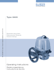
25-45-75-100-150-300
ACTIONNEUR ELECTRIQUE
ELECTRIC ACTUATOR
ELEKTRISCHER STELLANTRIEB
VR / VS
FR
DOCUMENTATION TECHNIQUE
MISE EN SERVICE
GB
TECHNICAL LITERATURE
SET UP PROCEDURE
D
TECHNISCHE UNTERLAGEN
BETRIEBSANLEITUNG
E
MAD
IN
EU
DSBA3400 - Révision : 17/01/2011
P. 1/32
Index
Instructions et consignes de sécurité...........................................................3
Montage mécanique....................................................................................... 4
Branchements électriques............................................................................. 6
Instructions and security................................................................................... 7
Mechanical mounting ...................................................................................... 8
Electric connection ........................................................................................... 10
Betriebsanleitung und Sicherheitshinweise ....................................................... 11
Mechanische Montage ..................................................................................... 12
Elektrische Verbindung ................................................................................... 14
Schéma électrique : Série V standard ........................................................... 15
Electric wiring : standard V range ..................................................................... 15
Schaltplan : standard V Serie ........................................................................... 15
Schéma électrique : Série V 400V.................................................................. 16
Electric wiring : standard V 400V...................................................................... 16
Schaltplan : standard V 400V ........................................................................... 16
Cartes électroniques...................................................................................... 17
Electronic cards ............................................................................................... 17
Elektronische Karten ........................................................................................ 17
Modèles FAILSAFE ............................................................. 18
FAILSAFE models ................................................................ 18
FAILSAFE Modele................................................................. 18
Modèles POSI - Branchements électriques........................ 20
POSI models - Electric connection......................................... 22
POSI Modele - Elektrische Verbindung .................................. 24
Modèles POSI - Carte électronique..................................... 27
POSI models - Electronic card ............................................... 27
POSI Modele - Regelkarte ..................................................... 27
Modèles GF3 - Schéma électrique ..................................... 28
GF3 models - Electric wiring ................................................. 28
GF3 Modele - Schaltplan ...................................................... 28
Données techniques ......................................................................................29
Technical data..................................................................................................29
Technischen daten...........................................................................................29
Liste des pièces détachées ........................................................................... 31
Spare parts list ................................................................................................. 31
Ersatzteilliste.................................................................................................... 31
DSBA3400 - Révision : 17/01/2011
P. 2/32
Instructions
FR
DESCRIPTION
Ces actionneurs électriques ont été conçus pour permettre le pilotage d’une vanne 1/4 tour. Pour tout autre application, nous
consulter préalablement. Nous ne pouvons être tenus responsables en cas d’autre utilisation.
CONSIGNES DE SECURITE
A lire avant toute installation du produit
• L’alimentation électrique doit être coupée avant toute intervention sur l’actionneur électrique (avant de démonter le capot ou de
manipuler la commande manuelle de secours).
• Toute intervention doit être effectuée par un électricien qualifié ou une personne formée aux règles d’ingénierie électrique, de
sécurité et tout autre directive applicable.
• Respecter impérativement l’ordre des consignes de raccordement et de mise en service décrites dans le manuel sans quoi le
bon fonctionnement n’est plus garanti. Vérifier les indications portées sur la plaque d’identification de l’actionneur : elles doivent
correspondre à votre réseau électrique d’alimentation.
• Le produit doit être protégé par un dispositif de sectionnement électrique adapté à sa puissance et facilement accessible.
• Le branchement à une prise de Terre est obligatoire au-delà de 42V suivant la norme en vigueur.
• Symboles utilisés :
Danger : risque de
choc électrique
Terre de protection
Tension continue
~ Tension alternative
TRANSPORT ET STOCKAGE
• Les transporteurs étant responsables des avaries et des retards de livraison, les destinataires doivent émettre des réserves, le
cas échéant, avant de prendre livraison des marchandises. Les envois directs d’usine sont soumis aux mêmes conditions.
• Le transport sur site est effectué dans un emballage rigide.
• Les produits doivent être stockés dans des endroits propres, secs et aérés, de préférence sur des palettes de manutention ou
sur des étagères.
MAINTENANCE
• La maintenance est assurée par notre usine. Si le matériel ne fonctionne pas, vérifier le câblage suivant le schéma électrique
et l’alimentation de l’actionneur électrique concerné.
• Pour toute question, prendre contact avec le service après-vente.
• Pour nettoyer l’extérieur de l’appareil, utiliser un chiffon (et de l'eau savonneuse).
NE PAS UTILISER D'AGENT A BASE DE SOLVANT OU D'ALCOOL
GARANTIE
• 100% des actionneurs ont été testés et réglés en usine.
• Ces produits sont garantis 2 ans ou 50000 manœuvres contre tous vices de fabrication et de matière, à partir de la date de
livraison (facteur de service et classe du modèle suivant la norme CEI34).
• Cette garantie n'est valable que dans le cas où le matériel aura été, entre temps, ni démonté, ni réparé. Cette garantie ne
s'étend pas à l'usure provoquée par suite de chocs ou maladresse, ainsi que par l'utilisation du matériel dans les conditions qui ne
seraient pas conforme à ses caractéristiques. Cette garantie est strictement limitée au remplacement de la ou des pièces d'origines reconnues défectueuses, par nos services, après expertise. Les frais de port aller et retour, ainsi que la main d'œuvre, restent
à la charge du client. Aucune responsabilité ne serait nous incomber au sujet des accidents ou risques directs ou indirects découlant d'une défectuosité de nos matériels. La garantie ne couvre pas les conséquences d'immobilisation et exclut tout versement
d'indemnité. Les accessoires et adaptations ne sont pas couverts par cette garantie. Au cas où le client n'aurait pas réalisé ponctuellement les paiements stipulés aux échéances convenues, notre garantie sera suspendue jusqu'au paiement des échéances
en retard et sans que cette suspension puisse augmenter la durée de la garantie à la mise à disposition.
RETOUR DE MARCHANDISE
• L'acheteur est tenu de vérifier au moment de la livraison la conformité de la marchandise par rapport à sa définition.
• L'acceptation par l'acheteur de la marchandise dégage le fournisseur de toute responsabilité, si l'acheteur découvre une nonconformité postérieurement à la date d'acceptation. Dans un tel cas, les frais de mise en conformité seront à la charge de l'acheteur qui supportera également seul, les conséquences financières du dommage. Les retours des marchandises sont acceptés
que si nous les avons préalablement autorisés : ils doivent nous parvenir franco de tous frais à domicile et ne comporter que des
produits dans leur emballage d’origine. Les marchandises rendues sont portées au crédit de l'acheteur, déduction faite des 20%
de reprise du matériel calculé sur la base du montant initial des marchandises retournées.
- Ne pas monter l’actionneur « tête en bas »..
- Ne pas monter l'actionneur à moins de 30 cm d’une source de perturbations
électromagnétiques
DSBA3400 - Révision : 17/01/2011
P. 3/32
Montage mécanique (Modèles VR)
FR
DIMENSIONS DE L’ACTIONNEUR
•
•
•
•
L’actionneur est par défaut en position fermée.
Fixations possibles : F05 (4xM6 sur Ø50) et F07 (4xM8 sur Ø70), étoile 17, profondeur 19mm.
Ne pas monter l’actionneur « tête en bas ».
Hauteur nécessaire pour monter l’actionneur : H=300mm au-dessus de la vanne.
COMMANDE MANUELLE DE SECOURS
L’actionneur fonctionne en priorité électrique. S’assurer que l’alimentation est coupée avant de le manœuvrer manuellement.
• Tourner le bouton de débrayage (annexe p.31 repère 9) vers la position MAN et le maintenir dans cette position.
• Tourner l’axe sortant de l’actionneur à l’aide d’une clé à molette.
• Pour réenclencher la réduction, relâcher le bouton de débrayage.
MONTAGE / DEMONTAGE DU CAPOT ET DE L’INDICATEUR DE POSITION
Il est nécessaire de démonter le capot pour le câblage et le réglage de l’actionneur.
• Montage du capot (annexe p.31 rep.2) : s’assurer que le joint (annexe p.31 rep.7) est bien dans son logement, monter le
capot et serrer les 4 vis M6 (annexe p.31 rep.3, couple : max. 6Nm).
• Montage de l’indicateur visuel (annexe p.31 rep.1) : emboîter l’indicateur sur l’axe sortant.
DSBA3400 - Révision : 17/01/2011
P. 4/32
Montage mécanique (Modèles VS)
FR
DIMENSIONS DE L’ACTIONNEUR
•
•
•
•
•
L’actionneur est par défaut en position fermée.
Fixations possibles : F07 (4xM8 sur Ø70) et F10 (4xM10 sur Ø102), étoile 22, profondeur 24mm.
Ne pas monter l’actionneur « tête en bas ».
Hauteur nécessaire pour monter l’actionneur : H=360mm au-dessus de la vanne.
Ne pas monter l'actionneur à moins de 30 cm d’une source de perturbations électromagnétiques .
COMMANDE MANUELLE DE SECOURS VS ET REGLAGE DES BUTEES
L’actionneur fonctionne en priorité électrique. S’assurer que l’alimentation est coupée avant de le manœuvrer manuellement..
Aucun débrayage n’est nécessaire, il suffit de tourner le volant (annexe p.32 repère 9).
Les butées mécaniques sont réglées par défaut à 90° et collées (Tubétanche Loctite 577 ou équivalent). Il est possible de les
ajuster en déplaçant les 2 vis M8 (annexe p.32 rep.17) mais il faut les recoller pour assurer une bonne étanchéité.
MONTAGE / DEMONTAGE DU CAPOT ET DE L’INDICATEUR
Il est nécessaire de démonter le capot pour le câblage et le réglage de l’actionneur.
• Montage du capot (annexe p.32 rep.2) : s’assurer que le joint (annexe p.32 rep.7) est bien dans son logement, monter le
capot et serrer les 4 vis M6 (annexe p.32 rep.3, couple : max. 6Nm).
• Montage de l’indicateur visuel (annexe p.32 rep.1) : monter le joint et l’indicateur puis le hublot avec les 4 vis M4.
Orientation du hublot pour un
montage standard
DSBA3400 - Révision : 17/01/2011
P. 5/32
Branchements électriques
FR
RESPECTER LES CONSIGNES DE SECURITE
Nos presse-étoupes (annexe p.31/32 rep.15) acceptent un câble de diamètre compris entre 7mm et 12mm. Les câbles utilisés
doivent supporter l’atmosphère ambiante (température maxi 70°).
• Retirer l’indicateur visuel, dévisser les 4 vis et retirer le capot.
CABLAGE DE L’ALIMENTATION ET DE LA COMMANDE (Sauf POSI - voir p.20)
• Vérifier sur l’actionneur que la tension indiquée sur l’étiquette (annexe p.31/32 rep.11) correspond à la tension du réseau.
• Connecter la terre avec la vis extérieure M5 sous les presse-étoupes (annexe p.31/32 rep.16).
Il est aussi possible de connecter la terre à l’intérieur de l’actionneur avec la vis M3 à coté du bornier (annexe p.17 rep.A).
• Dévisser le presse-étoupe gauche et passer le câble.
• Connecter les fils sur le bornier (annexe p.17 rep.B) suivant le mode de pilotage souhaité.
Mode 3 points modulants
N
-
N
-
Ph
+
Ouvrir
Mode Tout ou rien (fermé par défaut)
Ph
+
Ouvrir
Fermer
TP/PE
1
2
3
15V-30V 50/60Hz (12V-48V DC)
100V-240V 50/60Hz (100V-350V DC)
La température du bornier peut atteindre 90°C
TP/PE
1
2
NOTA BENE : Les câbles utilisés doivent être rigides
(tensions pour la recopie : 4 à 250V AC/DC)
NOTA BENE: L'actionneur étant branché en permanence, il doit être raccordé à un dispositif de sectionnement (interrupteur, disjoncteur), assurant la coupure
d'alimentation de l'appareil.
3
15V-30V 50/60Hz (12V-48V DC)
100V-240V 50/60Hz (100V-350V DC)
• Mettre un collier autour des fils (voir schéma ci-contre) et revisser le presse-étoupe.
Cosse ronde
pour la terre
CABLAGE DE LA RECOPIE
Collier de
serrage
Nos actionneurs sont par défaut équipés de 2 contacts fins de course auxiliaires secs
normalement ouverts (NO). Par défaut, la came blanche est utilisée pour détecter l’ouverture (FC1) et la came noire pour détecter la fermeture (FC2).
Cette recopie accepte une tension comprise entre 24V et 240V AC/DC.
• Dévisser le presse-étoupe droit et passer le câble.
• Enlever 25mm de gaine et dénuder chaque fil de 8mm.
• Connecter les fils sur le bornier (annexe p.31/32 rep.12) suivant le schéma ci-contre.
• Revisser le presse-étoupe.
REGLAGE DES CONTACTS FINS DE COURSE
L’actionneur est pré réglé en usine. Ne pas toucher les 2 cames inférieures sous peine de perturber le fonctionnement de l’actionneur voire d’endommager ce dernier.
• Pour ajuster la position des contacts auxiliaires, faire pivoter les 2 cames supérieures en utilisant la clé appropriée.
CLE DE REGLAGE
SETTING KEY
SCHLÜSSEL
CLE DE REGLAGE
SETTING KEY
SCHLÜSSEL
• Remonter le capot, visser les 4 vis et monter l’indicateur visuel.
DSBA3400 - Révision : 17/01/2011
P. 6/32
Instructions
GB
DESCRIPTION
These electric actuators have been designed to perform the control of a valve with 90° rotation. Please consult us for any different
application. We cannot be held responsible if the mentioned actuators are used in contradiction to this advice.
SAFETY INSTRUCTIONS
To be read prior to the installation of the product
• The electric power supply must be switched-off before any intervention on the electric actuator (i.e. prior demounting its cover
or manipulating the manual override knob).
• Any intervention must only be carried out by a qualified electrician or other person instructed in accordance with the regulations
of electric engineering, safety, and all other applicable directives.
• Strictly observe the wiring and set-up instructions as described in the manual: otherwise, the proper working of the actuator can
not be guaranteed anymore. Verify that the indications given on the identification label of the actuator fully correspond to the characteristics of the electric supply.
• The product must be protected by an easily accessible electric safety device (power isolator) corresponding to its power.
• As stipulated in the applicable regulation, the connection to earth contact is compulsory for devices with working voltages exceeding 42 V.
• Used symbols :
Danger : risk of
electric shock
Earth protection
Direct voltage
~ Alternating voltage
TRANSPORT AND STORAGE
• The forwarding agents being held as responsible for damages and delays of the delivered goods, the consignees are obliged to
express if applicable their reserves, prior to accept the goods. The goods delivered directly ex works are subject to the same conditions.
• The transport to the place of destination is carried out by using rigid packing material.
• The products must be stored in clean, dry, and ventilated places preferably on appropriate palettes or shelves.
MAINTENANCE
• Maintenance is ensured by our factory. If the supplied unit does not work, please check the wiring according to the electric diagram as well as the power supply of the concerned electric actuator.
• For any question, please contact our after-sales service.
• To clean the outside of the actuator, use a lint and soapy water.
DO NOT USE CLEANING PRODUCT WITH SOLVENT OR ALCOHOL
GUARANTEE
• 100% of the actuators are fully tested and set in the factory.
• These products are guaranteed two years from the delivery date or 50,000 operating cycles against all types of manufacturing
and material faults (operating time and model class according to standard CEI34).
• This guarantee will only be valid if the unit has not been disassembled or self-repaired during its service life. It does not cover
any wear and damage caused by shocks or faulty operation neither by the use of the unit under conditions not in accordance with
its nominal characteristics. The guarantee is strictly limited to the replacement of original parts found defective on checking by our
service personnel. The cost of shipping to our premises, the return of devices to the customer as well as the repair cost will be
chargeable. We will not assume the responsibility for any direct or indirect accidents/risks originated by a failure of our products.
The guarantee does not cover the consequences of breakdown and excludes any payments for indemnities. The accessories and
adaptations are excluded from the guarantee. In the case where a customer has not proceeded to payments within the agreed
period, our guarantee will be suspended until the delayed payments have been received and with the consequence that this suspension will not prolong the guarantee period in any case.
RETURN OF GOODS
• The customer is obliged to check the conformity of the goods with regard to their definition at the time of delivery.
• The acceptance of the goods by the purchaser disclaims the supplier of all responsibility if the purchaser discovers any non-
conformity after the date of acceptance. In such case, the repair cost will be borne by the purchaser who will also exclusively bear
all financial consequences of any resulting damage. Returned goods will only be accepted if our prior agreement has been given
to this procedure : the goods must be sent free of all cost and being shipped solely and in their original packing. The returned
goods will be credited to the purchaser with a reduction of 20% on the unit’s price charged in accordance with the original invoice
of the returned goods.
- Do not mount the actuator « upside down ».
- Do not mount the actuator less than 30 cm of a electromagnetic disturbances source.
DSBA3400 - Révision : 17/01/2011
P. 7/32
Mechanical mounting (VR models)
GB
DIMENSIONS OF THE ACTUATOR
•
•
•
•
The actuator is set to its closed position in our factory.
Possible fixations : F05 (4xM6 with Ø50) and F07 (4xM8 with Ø70), star 17, depth 19mm.
Do not mount the actuator « upside down ».
Necessary height above the valve for the mounting of the actuator : H=300mm.
EMERGENCY MANUAL OVERRIDE
In case of an electric supply failure, it is possible to operate the actuator manually :
• Turn the knob (appendix p.31 mark 9) to position MAN and hold it in position.
• Turn the outgoing drive shaft of the actuator with the help of an adjusting spanner.
• In order to re-engage the reduction, release the knob.
MOUNTING / DISASSEMBLY OF THE COVER AND POSITION INDICATOR
For the wiring and setting of the actuator, it is necessary to remove the cover.
• Mounting of the cover (appendix p.31 mark 2) : make sure that the seal ring (appendix p.31 mark 7) is correctly placed in its
position, mount the cover and tighten the 4 screws M6 (appendix p.31 mark 3, torque : max. 6Nm).
• Mounting of the position indicator (appendix p.31 mark 1) : fit the indicator onto the outgoing axle.
DSBA3400 - Révision : 17/01/2011
P. 8/32
Mechanical mounting (VS models)
GB
DIMENSIONS OF THE ACTUATOR
•
•
•
•
•
The actuator is set to its closed position in our factory.
Possible fixations : F07 (4xM8 with Ø70) and F10 (4xM10 with Ø102), star 22, depth 24mm.
Do not mount the actuator « upside down ».
Necessary height above the valve for the mounting of the actuator : H=360mm.
Do not mount the actuator less than 30 cm of a electromagnetic disturbances source.
EMERGENCY MANUAL OVERRIDE AND MECHANICAL STOPS SETTING
The actuator operates in electric priority. Ensure that the power supply is cut off prior to manually operation. No declutching is
required, the hand wheel has simply to be turned (appendix p.32 mark 9).
The end mechanical stops are preset to 90° and stuck (Tubetanche Loctite 577 or equivalent). It is posible to adjust then by
moving the 2 screws M8 (appendix p.32 mark 17) but you need to stick them again in order to ensure a proper sealing.
MOUNTING / DEMOUNTING OF THE COVER AND POSITION INDICATOR
For the wiring and setting of the actuator, it is necessary to remove the cover.
• Mounting of the cover (appendix p.32 mark 2) : make sure that the seal ring (appendix p.32 mark 7) is correctly placed in its
position, mount the cover and tighten the 4 screws M6 (appendix p.32 mark 3, torque : max. 6Nm).
• Mounting of the position indicator (appendix p.326 mark 1) : mount the seal ring and the indicator then the window with the
4 screws M4.
Sense of window for standard
mounting
DSBA3400 - Révision : 17/01/2011
P. 9/32
Electric connection
GB
RESPECT SAFETY INSTRUCTIONS
Our cable glands (appendix p.14 mark 31/32) are designed for cables with a diameter between 7mm and 12mm. The used
cables must be able to withstand the ambient conditions (maximum temperature 70°C).
• Remove the position indicator, unscrew the four screws and take off the cover.
SUPPLY AND CONTROL WIRING (Except POSI - see p.22)
• Ensure that the voltage indicated on the actuator ID label (appendix p.31/32 mark 11) corresponds to the voltage supply.
• Connect to earth through the exterior bolt M5 located under the cable gland (appendix p.31/32 mark 16). It is also possible
to connect the actuator to earth inside the actuator through the bolt M3 next to the terminal strip (appendix p.17 mark A).
• Unscrew the left cable gland and insert the cable.
• Connect the wires to the terminal strip (appendix p.17 mark B) in accordance with the required control mode.
3-points modulating mode
N
-
On-Off mode (pre-set to closed)
N
-
Ph
+
Ph
+
The terminal temperature can reach 90°C
NOTA BENE : The used wires must be rigid
Open
(feedback voltages : 4 to 250V AC/DC)
Open
Close
TP/PE
1
2
TP/PE
3
15V-30V 50/60Hz (12V-48V DC)
100V-240V 50/60Hz (100V-350V DC)
1
2
NOTA BENE: The actuator is always powered, so it
must be connected to a disconnection system (switch,
circuit breaker) to ensure the actuator power cut.
3
15V-30V 50/60Hz (12V-48V DC)
100V-240V 50/60Hz (100V-350V DC)
• Put a lacing cord around the wires (see the picture beside) and re-tighten the cable gland.
Earth round
terminal
WIRING OF THE FEEDBACK SIGNAL
Clamping
ring
Our actuators are equipped with two simple limit switch contacts normally set in their
open position (NO). As per factory setting, the white cam is used to detect the open
position (FC1) and the black cam is used to detect the closed position (FC2).
This feedback system accepts voltages between 24V and 240V AC/DC.
• Unscrew the right cable gland and insert the cable.
• Remove 25mm of the cable sheath and strip each wire by 8mm.
• Connect the wires to the terminal strip (appendix p.31/32 mark 12) in accordance
with the diagram beside.
• Tighten the cable gland.
SETTING OF END LIMIT SWITCHES
The actuator is pre-set in our factory. Do not touch the two lower cams in order to avoid any malfunctioning or even damage to
the actuator.
• To adjust the position of the auxiliary contacts, make rotate the two superior cams by using the appropriate wrench.
CLE DE REGLAGE
SETTING KEY
SCHLÜSSEL
CLE DE REGLAGE
SETTING KEY
SCHLÜSSEL
• Re-mount the cover, fasten the four screws and attach the position indicator.
DSBA3400 - Révision : 17/01/2011
P. 10/32
Instruktionen
D
BESCHREIBUNG
Die elektrischen Stellantriebe wurden entwickelt, um Ventile mit Vierteldrehung zu steuern. Bitte ziehen Sie uns vor jeder anderen
Verwendung zur Rate. Für jeglichen weitergehenden Einsatz können wir keine Verantwortung übernehmen.
SICHERHEITSHINWEISE
Vor jeglicher Installation des Produktes zu lesen
• Die Stromzufuhr muss vor jeglichem Eingriff am elektrischen Stellantrieb unterbrochen werden (bevor die Haube abgenommen
oder die Handnotbetätigung bedient wird).
• Jeglicher Eingriff darf nur von qualifizierten Elektrikern oder von nach den Regeln der Elektrotechnik, der Sicherheit und allen
anderen anwendbaren Normen geschultem Personal vorgenommen werden.
• Beachten Sie unbedingt die Reihenfolge der Anweisungen zum Anschliessen und zur Inbetriebnahme, welche im Handbuch
beschrieben werden, ansonsten wird die einwandfreie Funktion nicht gewährleistet. Überprüfen Sie die Angaben auf dem Typenschild des Stellantriebes : sie müssen Ihrer Stromversorgung entsprechen.
• Das Produkt muß durch eine Vorrichtung zur Unterbrechung des Stromkreislaufes geschützt sein, welche an seine Leistung
angepasst und leicht zugänglich sein muß.
• Die Erdung ist nach der geltenden Norm bei über 42V vorgeschrieben.
• Verwendete Symbole :
Gefahr : Gefahr eines
elektrischen Schlages
Schutzerdung
Gleichspannung
~ Wechselspannung
TRANSPORT UND LAGERUNG
• Da die Spediteure für Schäden und Lieferverspätungen verantwortlich sind, müssen die Empfänger gegebenenfalls vor Annahme der Waren Vorbehalte äußern. Lieferungen direkt ab Werk unterliegen den gleichen Bedingungen.
• Der Transport vor Ort erfolgt in einer festen Verpackung.
• Die Lagerung muss an einem sauberen, gelüfteten und trockenen Ort erfolgen, bevorzugt auf Transportpaletten oder in Regalen.
WARTUNG
• Die Wartung wird in unserem Werk vorgenommen. Falls das Material nicht funktioniert, überprüfen Sie bitte die Kabelanschlüsse nach dem Schaltplan und die Stromzufuhr des betreffenden elektrischen Stellantriebes.
• Bei Fragen wenden Sie sich bitte an den Kundendienst.
• Zur äusseren Reinigung des Gerätes ein Tuch und Seifenwasser verwenden.
BITTE NIE LÖSUNGSMITTEL ODER ALKOHOLHALTIGE MITTEL ZUR REINIGUNG BENUTZEN.
GARANTIE
• 100% der Stellantriebe werden im Werk geprüft und eingestellt.
• Die Produkte unterliegen einer Garantie von zwei Jahren oder 50000 Bedienvorgängen bezüglich allen Herstellungs- und Ma-
terialfehlern, vom Datum der Auslieferung an (Einschaltdauer und Modellklasse nach Norm CEI34).
• Diese Garantie tritt nur in Kraft, wenn die Ware zwischenzeitlich weder repariert noch zerlegt worden ist. Sie bezieht sich weder
auf Verschleiß durch Stöße oder Fehlbedienung noch auf den Einsatz des Materials unter nicht geeigneten Bedingungen. Diese
Garantie ist eingeschränkt auf den Ersatz des oder der Originalteile, die von uns nach Begutachtung als defekt anerkannt wurden.
Die Frachtkosten für Hin- und Rückweg sowie der Arbeitslohn obliegen dem Kunden. Wir übernehmen keinerlei Verantwortung
bezüglich Unfällen oder direkten oder indirekten Risiken, die sich aus einem Defekt unserer Waren ergeben. Die Garantie deckt
die Folgen eines Stillstandes nicht ab und schließt jede Entschädigungs-zahlung aus. Zubehör und Umbauten fallen nicht unter
die Garantie. Für den Fall, daß der Kunde zeitweise nicht den Zahlungen zu den vereinbarten Fälligkeiten nachgekommen ist,
wird die Garantie bis zur Zahlung der verspäteten Fälligkeiten ausgesetzt, ohne daß diese Unterbrechung die Dauer der gewährleisteten Garantie verlängert.
RÜCKSENDUNG VON WAREN
• Der Käufer ist gehalten, bei Erhalt der Ware die Übereinstimmung mit den Vorgaben zu überprüfen.
• Die Annahme der Ware durch den Käufer befreit den Lieferanten von jeglicher Verantwortung, falls der Käufer eine Reklamati-
on nach dem Zeitpunkt der Annahme feststellt. In einem solchen Fall obliegen dem Käufer allein die Kosten für die Beseitigung
sowie die Folgekosten des Schadens. Warenrücksendungen werden nur angenommen, wenn wir sie zuvor genehmigt haben: sie
müssen frei Haus, ohne jegliche Gebühren, an unseren Firmensitz geliefert werden und dürfen ausschliesslich originalverpackte
Ware enthalten. Die zurückgesendeten Waren werden dem Käufer gutgeschrieben, abzüglich 20% Warenrücksendungspauschale, veranschlagt auf Grundlage des ursprünglichen Rechnungsbetrags der zurückgesandten Waren.
- Antrieb nie “Kopf uber” einbauen.
- Immer einen Mindestabstand von 30cm zu einer elektromagnetischens Störquelle einhalten .
DSBA3400 - Révision : 17/01/2011
P. 11/32
Mechanische Montage (VR modele)
D
DIMENSIONEN DES STELLANTRIEBES
•
•
•
•
Der Stellantrieb wird mit Voreinstellung Position geschlossen geliefert.
Mögliche Befestigungen : F05 (4xM6 bei Ø50) und F07 (4xM8 bei Ø70), Stern 17, Tiefe 19mm.
Den Stellantrieb nicht kopfüber anbringen.
Notwendige Höhe zur Anbringung des Stellantriebes : H=300mm über dem Ventil.
HANDNOTBETÄTIGUNG
Die Priorität der Funktion des Antriebs ist Automatikbetrieb. Bitte prüfen, dass die Stromversorgung abgeschaltet ist bevor der
Antrieb von Hand betätigt wird .
• Stellen Sie den Schalter (Anhang Seite 31 Markierung 9) auf MAN um und halten Sie ihn in dieser Position.
• Drehen Sie die Achse des Stellantriebes mit Hilfe eines Rollgabelschlüssels.
• Um die Reduktion wieder einzukuppeln, lassen Sie den Kupplungsschalter los.
ANBRINGUNG UND ABNEHMEN DER HAUBE UND DES STELLANZEIGERS
Es ist notwenig, zur Verkabelung und Einstellung des Stellantriebes die Haube abzunehmen.
• Anbringung der Haube (Anhang Seite 31 Markierung 2) : darauf achten, daß der Dichtring (Anhang Seite 31 Markierung 7)
richtig sitzt, die Haube anbringen und die 4 Schrauben M6 anziehen (Anhang Seite 31 Markierung 3, Drehmoment : max. 6Nm).
• Anbringung des Stellanzeigers (Anhang Seite 31 Markierung 1) : der Stellanzeiger wird auf die ausgehende Achse aufgesteckt.
DSBA3400 - Révision : 17/01/2011
P. 12/32
Mechanische Montage (VS modele)
D
DIMENSIONEN DES STELLANTRIEBES
•
•
•
•
•
Der Stellantrieb wird mit Voreinstellung Position geschlossen geliefert.
Mögliche Befestigungen : F07 (4xM8 bei Ø70) und F10 (4xM10 bei Ø102), Stern 22, Tiefe 24mm.
Den Stellantrieb nicht kopfüber anbringen.
Notwendige Höhe zur Anbringung des Stellantriebes : H=360mm über dem Ventil.
Berücksichtigen bei der Montage des Antriebs einen Mindestabstand von 30cm zu elektromagnetischen Störquellen.
HANDNOTBETÄTIGUNG UND EINSTELLUNG DER ENDHALTERUNGEN
Der Stellantrieb wird vorrangig elektrisch betrieben. Vor manueller Inbetriebnahme sicherstellen, dass die Stromzufuhr unterbrochen ist. Ein Auskuppeln ist nicht erforderlich, es reicht aus, das Steuerrad zu drehen (Anhang Seite 32 Markierung 9).
Die mechanischen Endhalterungen sind ab Werk auf 90° voreingestellt und geklebt (Tubetanche Loctite 577 oder mit entsprechender Spezifikation). Sie lassen sich durch Versetzen der beiden Schrauben M8 verstellen (Anhang Seite 32 Markierung 17),
aber sie müssen danach geklebt sein um die Abdichtung zu beachten.
ANBRINGUNG UND ABNEHMEN DER HAUBE UND DES STELLANZEIGERS
Es ist notwenig, zur Verkabelung und Einstellung des Stellantriebes die Haube abzunehmen.
• Anbringung der Haube (Anhang Seite 32 Markierung 2) : darauf achten, daß der Dichtring (Anhang Seite 32 Markierung 7)
richtig sitzt, die Haube anbringen und die 4 Schrauben M6 anziehen (Anhang Seite 32 Markierung 3, Drehmoment : max. 6Nm).
• Anbringung des Stellanzeigers (Anhang Seite 32 Markierung 1) : den Dichtring und den Stellanzeiger anbringen, schließlich
die Glasabdeckung mit den 4 Schrauben M4 befestigen.
Orientierung des Glasabdeckung
für eine Standardmontage
DSBA3400 - Révision : 17/01/2011
P. 13/32
Elektrische Verbindung
D
BEACHTEN SIE UNBEDINGT DIE SICHERHEIT ANWEISUNGEN
Unsere Kabelverschraubungen (Anhang Seite 31/32 Markierung 15) sind zulässig für Kabel mit einem Durchmesser zwischen
7mm und 12mm. Die verwendeten Kabel müssen der Umgebungsluft standhalten (maximale Temperatur 70°C).
• Den Stellanzeiger abziehen, die vier Schrauben lösen und die Haube abnehmen.
VERKABELUNG DER STROMZUFUHR UND DER STEUERUNG (außer POSI - p.24)
• Überprüfen Sie am Stellantrieb, daß die angegebene Spannung auf dem Typenschild (Anhang Seite 31/32 Markierung 11) der
Spannung des Netzes entspricht.
• Schließen Sie die Erdung mit der Aussenschraube M5 unter den Kabelverschraubungen (Anhang Seite 31/32 Markierung 16)
an.
• Es ist ebenso möglich, die Erdung innen am Stellantrieb neben der Klemmleiste mit der Schraube M3 anzuschliessen (Anhang
Seite 17 Markierung A).
• Lösen Sie die linke Kabelverschraubung und führen Sie das Kabel durch.
• Schließen Sie die Drähte an der Klemmleiste an (Anhang Seite 17 Markierung B), je nach gewünschter Steuerungsart.
3-Punkt-Modus
N
-
Auf-Zu Modus (Voreinstellung geschlossen)
N
-
Ph
+
Auf
Auf
Zu
TP/PE
1
2
TP/PE
3
1
15V-30V 50/60Hz (12V-48V DC)
100V-240V 50/60Hz (100V-350V DC)
Die Terminal-Temperatur kann bis zu 90°C erreichen.
Ph
+
2
NOTA BENE: Die Anschlusskabel müssen biegesteif
sein (Rückmeldespannungen 4 bis 250V AC/DC)
NOTA BENE: Da der Antrieb dauernd eingeschaltet ist,
muss er mit einem Sicherungsdispositiv (Unterbrecher
… ), verbunden sein, um eine Abschaltung durch Unterbrechung der Versorgungsspannung zu ermöglichen.
3
15V-30V 50/60Hz (12V-48V DC)
100V-240V 50/60Hz (100V-350V DC)
• Einen Kabelbinder um die Drähte legen (s. nebenstehende Skizze) und die Kabelverschraubung wieder befestigen.
Erdung rund
Anschluss
Klemmband
VERKABELUNG DER RÜCKMELDUNG
Unsere Stellantriebe sind defaultmässig mit 2 einfachen Endschalterkontakten versehen,
welche normalerweise geöffnet sind (NO). Gemäß Voreinstellung dient die weisse Nocke
dazu, die Öffnung zu erfassen (FC1) und die schwarze Nocke, um das Schliessen zu erfassen (FC2).
Diese Rückmeldung ist geeignet für eine Spannung zwischen 24V und 240V AC/DC.
• Lösen Sie die Kabelverschraubung und führen Sie das Kabel durch.
• Entfernen Sie 25mm der Ummantelung und legen Sie jeden Draht auf 8mm frei.
• Schließen Sie die Drähte nach dem nebenstehenden Schema an der Klemmleiste
(Anhang Seite 31/32 Markierung 12) an.
• Die Kabelverschraubung wieder befestigen.
EINSTELLUNG DER ENDSCHALTERKONTAKTE
Der Stellantrieb wird im Werk voreingestellt. Berühren Sie die beiden unteren Nocken nicht, da sonst die Funktion des Stellantriebes gestört oder letzterer sogar beschädigt werden kann.
• Um die Position der Hilfskontakte einzustellen, drehen Sie die beiden oberen Nocken unter Zuhilfenahme eines geeigneten
Schlüssels.
CLE DE REGLAGE
SETTING KEY
SCHLÜSSEL
CLE DE REGLAGE
SETTING KEY
SCHLÜSSEL
• Die Haube wieder anbringen, die vier Schrauben anziehen und den Stellanzeiger aufstecken.
DSBA3400 - Révision : 17/01/2011
P. 14/32
Schéma électrique : Série V : 100V - 240V AC (50/60Hz) et 100V - 350V DC ou 15V - 30V AC (50/60Hz) et 12V - 48V DC FR GB D
Electric wiring : V range: 100V - 240V AC (50/60Hz) and 100V - 350V DC or 15V - 30V AC (50/60Hz) and 12V - 48V DC
Schaltplan : Serie V : 100V - 240V AC (50/60Hz) und 100V - 350V DC oder 15V - 30V AC (50/60Hz) und 12V - 48V DC
La température du bornier peut atteindre 90°C
The terminal temperature can reach 90°C
Die Terminal-Temperatur kann bis zu 90°C erreichen.
- Les câbles utilisés doivent être rigides (tensions pour la recopie : 4 à 250V AC/DC)
- N.B.: The used wires must be rigid (feedback voltages : 4 to 250V AC/DC)
- N.B.: Die Anschlusskabel müssen biegesteif sein (Rückmeldespannungen 4 bis 250V AC/DC)
REP
FC0
Fin de course ouverture
Open limit switch
Endschalter AUF
FCF
Fin de course fermeture
Close limit switch
Endschalter ZU
FC1
Fin de course auxiliaire 1
Auxiliary limit switch 1
Zusätzlicher Endschalter 1
FC2
Fin de course auxiliaire 2
Auxiliary limit switch 2
Zusätzlicher Endschalter 2
CABLAGE CLIENT SUGGERE / SUGGESTED CUSTOMER WIRING
EMPFOHLENE VERDRAHTUNG
Mode 3 points modulants
3-points modulating mode
3-Punkt-Modus
Ph
+
N
-
Ph
+
D1/D2
Fermer
Close
Zu
TP/PE
TP/PE
1
2
3
4
3
A
TP/PE
2
100V-240V 50/60Hz (100V-350V DC)
15V-30V 50/60Hz (12V-48V DC)
5
6
7
8
9
A
D1
D2
FC1
1
3
FCF
2
FC0
1
COMMUN FC2
COMMON
RECOPIE FC2 GEMEINSAM
FEEDBACK
RÜCKMELDUNG
RECOPIE / FEEDBACK
RÜCKMELDUNG
COMMUN FC1
COMMON
RECOPIE FC1 GEMEINSAM
FEEDBACK
RÜCKMELDUNG
Ouvrir
Open
Auf
Ouvrir
Open
Auf
Bornier report défaut (24V DC / 3A max)
Failure report Terminal strip (24V DC / 3A max)
Fehlermeldung Klemmleiste (24V DC / 3A max)
FC2
N
-
Mode Tout ou rien (ON/OFF)
On-Off mode
Auf-Zu Modus
DESIGNATION / BESCHREIBUNG
~
17
Mode ON/OFF obligatoire
ON/OFF mode compulsory
ON/OFF Modus notwendig
18
—
C
+
~
Version
Failsafe
EBS.24
B
SNAA690000
M
DSBA3400 - Révision : 17/01/2011
P. 15/32
Schéma électrique : Série V 400V
Electric wiring : standard V 400V
Schaltplan : standard V 400V
D
ALIMENTATION COMMANDE
CONTROL POWER SUPPLY
STELLERSPANNUNG
CABLAGE CLIENT SUGGERE
SUGGESTED CUSTOMER WIRING
EMPFOHLENE VERDRAHTUNG
ALIMENTATION MOTEUR
MOTOR POWER SUPPLY
SPANNUNGSVERSORGUNG MOTOR
FR GB
BORNIER MOTEUR
TERMINAL BLOCK MOTOR
ANSCHLUSSBLOCK MOTOR
REP
DESIGNATION
BESCHREIBUNG
REP
DESIGNATION
BESCHREIBUNG
FC0
Fin de course ouverture
Open limit switch
Endschalter AUF
H4
Signalisation alimentation moteur
Motor supply indication
Rückmeldungmotorspannung
FCF
Fin de course fermeture
Close limit switch
Endschalter ZU
H5
Signalisation alimentation commande
Control supply indication
Rückmeldungstellerspannung
FC1
Fin de course auxiliaire 1
Auxiliary limit switch 1
Zusätzlicher Endschalter 1
KM1
Contact ouverture
Opening swith
Öffner
FC2
Fin de course auxiliaire 2
Auxiliary limit switch 2
Zusätzlicher Endschalter 2
KM2
Contact fermeture
Closing swith
Schliesser
S5
Poussoir d’arrêt
Stop button
Stopschalter
F1
Contact thermique
Thermical switch
Thermoschalter
S6
Poussoir d’ouverture
Opening button
Startschalter
F2
Contact thermique
Thermical switch
Thermoschalter
S7
Poussoir de fermeture
Closing button
Ausschalter
H
Résistance de réchauffage
Heating resistor
Heizwiderstand
M
Moteur
Motor
Motor
T
Thermostat
Thermoswitch
Thermoschalter
ERT.B
- L’alimentation du moteur est câblée sur un relais bistable triphasé à inversion de phase (non livré)
- The motor power supply is wired on bistable three-phase relay (not delivered)
- Anschluss des Motors ist auf einem bistabiles Drehstrom-Relais mit Phasenumkehrung verkabelt (nicht geliefert)
- En cas de fonctionnement inverse, inverser 2 des phases du moteur
- If working inverted, invert 2 phases of motor
- Bei umgekehrter Laufrichtung, umkehren sie die beiden Phasen des Motors
DSBA3400 - Révision : 17/01/2011
P. 16/32
Cartes électroniques
FR GB
Electronic cards
Elektronische Karten
Cartes d’alimentation et commande
Pilot and power supply cards
Steuerung und Stromversorgung Karten
SNAA730100
15V-30V 50/60Hz (12V-48V DC)
A
Rep.
A
B
*C*
D
E**
F
G
*
C
B
C
D
G
SNAA730000
100V-240V 50/60Hz (100V-350V DC)
F
F
E
E
D
D
A
C
Désignation
Designation
Vis de terre
Bornier alimentation et commande
Fusibles protection carte
LED 2 : microprocesseur ok
LED 3 : défaut détecté
LED 1 : présence tension
Bornier report défaut (24V DC - 3A max)
Earth screw
Pilot and power supply terminal strip
Card protection fuses
LED 2 : microprocessor ok
LED 3 : detected failure
LED 1 : power presence
Failure reportTerminal strip (24V DC - 3A max)
B
C
G
Bezeichnung
Erde Schraube
Steuerung und Stromversorgung Verbindung
Karte Sicherung
LED 2 : Mikroprozessor ok
LED 3 : Aufgespürter Fehler
LED 1 : Spannungsanwesenheit
Fehlermeldung Klemmleiste (24V DC - 3A max)
Fusibles pour carte multi-tensions / Fuses for multivolt card / Sicherung für Multispannung Karte :
- Carte / Card / Karte SNAA730100 : 5A / T 125V (Littelfuse 39615000000)
- Carte / Card / Karte SNAA730000 : 3,15A / T 250V (Multicomp MST 3,15A 250V)
** Défauts possibles : limitation de courant, limitation thermique ou erreur programme
=> vérifier que le couple de la vanne n’est pas supérieur au couple maximum fourni par l’actionneur
=> vérifier que l’actionneur ne dépasse pas la durée sous tension donnée (surchauffe possible)
Pour redémarrer l’actionneur, inverser le sens de marche ou l’éteindre et le remettre sous tension.
Possible defects : limitation of current, thermic limitation or program error
=> check that the valve torque is not superior to the maximum torque stand by the actuator
=> check that the actuator do not exceed the duty cycle indicated (possible overheat)
To re-start the actuator, reverse the sense of rotation or switch the power off and on.
Mögliche Fehler : Strombegrenzung, thermische Begrenzung oder Programmsfehler
=> Überprüfen sie das Drehmoment von dem Ventil
=> Überprüfen sie das die Einschaltdauer nicht grober als spezifisiert in die technischen Daten von den Antrieb ist
Um die Antrieb neue zu starten, muss man den Drehrichtung auswechseln oder die Spannung Auf/Zu Umschalten.
DSBA3400 - Révision : 17/01/2011
P. 17/32
Modèles FAILSAFE
FR GB
D
FAILSAFE models
FAILSAFE Modele
DESCRIPTION
DESCRIPTION
BESCHREIBUNG
Système de sécurité (mode Tout ou Rien obligatoire) Pour des actionneurs VR / VS
Safety system (ON/OFF mode compulsory) For VR / VS actuators
Sicherheitssystem (ON/OFF Modus notwendig) Für VR / VS Stellantriebe
DONNEES TECHNIQUES
TECHNICAL DATA
TECHNISCHE DATEN
TYPE
Tension
Voltage
Spannung
Courant nominal
Nominal current
Nennstrom
Courant maximal
Maximal current
Max. Strom
Durée initiale de charge
Initial loading time
Ladezeit
Relais de report d’état de la charge
Load state feedback relay
Rückmelderelais für Ladezustand
Température
Temperature
Temperatur
DSBA3400 - Révision : 17/01/2011
EBS.24
24V DC
0,8A
2,4A
14h max
250V AC 50/60Hz - 5A max
30V DC - 5A max
-10°C à/to/bis 40°C
P. 18/32
Modèles FAILSAFE
FR GB
D
FAILSAFE models
FAILSAFE Modele
BLOC BATTERIE 24V DC
24V DC BATTERY BLOCK
24V DC BATTERIE BLOCK
E- : fil noir
black wire
schwarz Faden
F+
SNAA550000
F+ : fil rouge
red wire
rot Faden
Bloc de sécurité
Failsafe security block
Sicherheitsblock
E-
65
66
17
17
18
18
Batterie chargée : contact fermé
Loaded battery : closed contact
Beladene Batterie : geschlossener Kontakt
Configuration
A
OU
B
Configuration
A
OR
B
Konfiguration
A ODER B
Fermé par défaut / Pre-set to closed / Voreinstellung geschlossen
1
2
B
SNAA510000
SNAA560000
REPORT D’ETAT DE
LA CHARGE
LOAD STATE
FEEDBACK
RÜCKMELDUNG VON
LADEZUSTAND
Carte alimentation et commande
Pilot and power supply card
Steuerung und Stromversorgung Karte
3
Mode Tout ou rien
On-Off mode
Auf-Zu Modus
A
Ouvrir
Open
Auf
N
-
Ph
+
Configuration A ou B :
A- Mode standard : en cas de pilotage de l’actionneur avec un automate, le report d’état de la charge peut être connecté à celui-ci
pour plus de sécurité.
B- Mode de sécurité totale (en utilisant le relais de report d’état, bornes 65 et 66) : l’actionneur n’ouvrira la vanne que si le bloc de
sécurité est opérationnel (charge suffisante, carte initialisée).
Configuration A or B :
A- Standard mode : when piloting the actuator with an automat (PLC), the load state feedback can be connected to it for more safety.
B- Total security mode (using the feedback relay, terminals 65 and 66) : the actuator will open only if the
rational (sufficient loading, initialized card).
security block is ope-
Konfiguration A oder B :
A- Standard Modus : Im Fälle der Steuerung des Antrieb mit einer Automat kann der Rückmeldung des
diesen hier für Sicherheit angeschlossen sein.
Batteriesladung an
B- Total Sicherheit Modus (mit benutzung des Rückmeldungsrelais, Klemmen 65 und 66) : der Antrieb wird den Hahn nur öffnen
wenn das Sicherheitsblock geladen ist (gemïgenede Ladung, initializierte Karte).
DSBA3400 - Révision : 17/01/2011
P. 19/32
Modèles POSI - Branchements électriques
RESPECTER LES CONSIGNES DE SECURITE
FR
ACTIONNEUR DEJA PRE-REGLE EN USINE
Nos presse-étoupes (annexe p.31/32 rep.15) acceptent un câble de diamètre compris entre 7mm et 12mm. Les câbles utilisés
doivent supporter l’atmosphère ambiante (température maxi 70°).
• Retirer l’indicateur visuel, dévisser les 4 vis et retirer le capot.
CABLAGE DE L’ALIMENTATION
• Vérifier sur l’actionneur que la tension indiquée sur l’étiquette (annexe p.31/32 rep.11) correspond à la tension du réseau.
• Connecter la terre avec la vis extérieure M5 sous les presse-étoupes (annexe p.31/32 rep.16). Pour la version multitensions, il est aussi possible de connecter la terre à l’intérieur de l’actionneur avec la vis M3 à coté du bornier.
• Dévisser le presse-étoupe gauche et passer le câble.
• Connecter les fils sur le bornier de la carte alimentation (annexe p.31/32 rep.14).
N
-
Ph
+
TP/PE
1
2
3
15V-30V 50/60Hz (12V-48V DC)
100V-240V 50/60Hz (100V-350V DC)
• Mettre un collier autour des fils (voir schéma ci-contre) et revisser le presse-étoupe.
Cosse ronde
pour la terre
Collier de
serrage
CABLAGE CONSIGNE ET RECOPIE DE LA CARTE P5
Afin de limiter les perturbations électromagnétiques, l’utilisation de câbles blindés est obligatoire (câbles supérieurs à 3m).
• Dévisser le presse-étoupe droit et passer le câble.
• Connecter la consigne entre les bornes 15 et 16 (annexe p.27 rep.B).
La borne 15 est la polarité négative (-) et la borne 16 la polarité positive (+).
• Connecter la recopie entre les bornes 13 et 14 (annexe p.27 rep.C).
La borne 13 est la polarité positive (+) et la borne 14 la polarité négative (-).
• Revisser le presse-étoupe.
Montage départ usine : par défaut, consigne et recopie en 4-20mA, sens normal.
Pour reparamétrer la carte : voir page suivante, « Séquence de paramétrage ».
Pour vérifier le bon fonctionnement de la carte : voir page suivante, « Mode de fonctionnement normal ».
Type 0-20 ou 4-20mA : 5V DC max
La température du bornier peut atteindre 90°C
N.B. : L'actionneur étant branché en permanence, il doit être raccordé à un dispositif de sectionnement
(interrupteur, disjoncteur), assurant la coupure d'alimentation de l'appareil.
N.B. : Les câbles utilisés doivent être rigides. (tensions pour la recopie : 4 à 250V AC/DC)
DSBA3400 - Révision : 17/01/2011
P. 20/32
Modèles POSI - Branchements électriques
FR
SEQUENCES DE PARAMETRAGE
1 Positionnement des cavaliers K1, K2 et K3
- Positionner les cavaliers d’après le tableau suivant (avant chaque modification, mettre la carte hors
tension) :
ON
OFF
K3 OFF
K3 ON
Consigne
Recopie
Cavalier K1
A
B
Cavalier K2
A
B
0-10V
0-10V
0-10V
0-20mA
0-20mA
0-20mA
4-20mA
4-20mA
4-20mA
0-10V
0-20mA
4-20mA
0-10V
0-20mA
4-20mA
0-10v
0-20mA
4-20mA
ON
ON
ON
OFF
OFF
OFF
OFF
OFF
OFF
ON
OFF
OFF
ON
OFF
OFF
ON
OFF
OFF
OFF
OFF
OFF
ON
ON
ON
ON
ON
ON
Cavalier K3
OFF
ON
ON
OFF
ON
ON
OFF
ON
ON
OFF
OFF
ON
OFF
OFF
ON
OFF
OFF
ON
2 Choix du sens de la vanne
2.1 Sens normal (par défaut)
- Appuyer sur OPEN et mettre la carte sous tension en maintenant le bouton enfoncé.
- La LED verte s’allume. Relâcher le bouton OPEN.
- Débrancher la carte.
G
2.2 Sens inverse
- Appuyer sur CLOSE et mettre la carte sous tension en maintenant le bouton enfoncé.
- La LED rouge s’allume. Relâcher le bouton CLOSE.
- Débrancher la carte.
R
3 Choix du type de consigne
3.1 Consigne en tension 0-10V
- Appuyer sur MEM et mettre la carte sous tension en maintenant le bouton enfoncé.
- La LED rouge clignote 3 fois. Relâcher le bouton.
- Débrancher la carte.
R
3.2 Consigne en courant 0-20mA
- Appuyer sur MEM et OPEN et mettre la carte sous tension en maintenant les boutons enfoncés.
- La LED rouge clignote 3 fois. Relâcher les boutons.
- Débrancher la carte.
R
3.3 Consigne en courant 4-20mA (par défaut)
- Appuyer sur MEM et CLOSE et mettre la carte sous tension en maintenant les boutons enfoncés.
- La LED rouge clignote 3 fois. Relâcher les boutons.
- Débrancher la carte.
R
4 Mode apprentissage
G
R
- Appuyer sur OPEN et CLOSE et mettre la carte sous tension en maintenant les boutons enfoncés.
- Les 2 LEDs s’allument. Relâcher les boutons, les 2 LEDs s’éteignent. Le mode apprentissage est
sélectionné.
R
R
- Appuyer sur CLOSE pour faire venir la vanne en position fermée. La LED rouge s’allume.
- Mémoriser la position fermée par MEM + CLOSE, la LED rouge clignote 2 fois pour acquitter.
- Appuyer sur OPEN pour faire venir la vanne en position ouverte. La LED verte s’allume.
- Mémoriser la position ouverte par MEM + OPEN, la LED verte clignote 2 fois pour acquitter.
G
G
- Les positions sont mémorisées, débrancher la carte.
MODE DE FONCTIONNEMENT NORMAL
- Mettre la carte sous tension. La LED verte clignote 3 fois.
- Lors du fonctionnement normal, la LED verte s’allume lorsque le moteur ouvre la vanne, et la LED
rouge lorsque le moteur ferme la vanne.
- Lorsque les 2 LEDs sont éteintes, le moteur n’est pas sollicité.
G
G
R
- En cas de couple trop important, les 2 LEDs s’allument pour indiquer la limitation et l’actionneur
s’arrête. Pour le redémarrer, il faut soit inverser le sens de marche, soit éteindre et remettre sous tension la carte.
DSBA3400 - Révision : 17/01/2011
P. 21/32
POSI models - Electric connection
RESPECT SAFETY INSTRUCTIONS
GB
ACTUATOR PRE-SET IN FACTORY
Our cable glands (appendix p.31/32 mark 15) are designed for cables with a diameter between 7mm and 12mm. The used
cables must be able to withstand the ambient conditions (maximum temperature 70°C).
• Remove the position indicator, unscrew the four screws and take off the cover.
POWER SUPPLY WIRING
• Ensure that the voltage indicated on the actuator ID label (appendix p.31/32 mark 11) corresponds to the voltage supply.
• Connect to earth through the exterior bolt M5 located under the cable gland (appendix p.31/32 mark 16). For multivolt version, it is also possible to connect the actuator to earth inside the actuator through the bolt M3 next to the terminal strip.
• Unscrew the left cable gland and insert the cable.
• Connect the wires to the power supply card’s terminal strip (appendix p.31/32 mark 14).
N
-
Ph
+
TP/PE
1
2
3
15V-30V 50/60Hz (12V-48V DC)
100V-240V 50/60Hz (100V-350V DC)
• Put a lacing cord around the wires (see the picture beside) and re-tighten the cable
gland.
Earth round
terminal
Clamping
ring
POSITIONING CARD WIRING (OUTPUT AND INPUT SIGNAL)
In order to avoid electromagnetic perturbations, it is compulsory to use shielded cables (cables longer than 3m).
• Unscrew the right gland and pass the cable.
• Connect the input signal between terminals 15 and 16 (appendix p.27 mark B).
Terminal 15 is the negative polarity (-) and terminal 16 is the positive polarity (+).
• Connect the output signal between terminals 13 and 14 (appendix p.27 mark B).
Terminal 13 is the positive polarity (+) and terminal 14 is the negative polarity (-).
• Tighten the cable gland.
Factory setting : by default, 4-20mA input and output signals with normal rotation sense.
To proceed to a new setting of the card : please see next page, “Parameter selection sequence”.
To check the proper operation of the card : please see next page, “Normal operating mode”.
Type 0-20 or 4-20mA : 5V DC max.
The terminal temperature can reach 90°C
N.B.: The actuator is always powered, so it must be connected to a disconnection system (switch, circuit
breaker) to ensure the actuator power cut.
N.B.: The used wires must be rigid (feedback voltages : 4 to 250V AC/DC)
DSBA3400 - Révision : 17/01/2011
P. 22/32
POSI models - Electric connection
GB
PARAMETER SELECTION SEQUENCE
1 Shunts positioning K1, K2 and K3
ON
- Position the shunts as follows (before modification, switch off the card) :
Input signal
Output signal
Schunt K1
Schunt K2
A
B
A
B
0-10V
0-10V
ON
OFF
ON
OFF
0-10V
0-20mA
ON
OFF
OFF
ON
0-10V
4-20mA
ON
OFF
OFF
ON
0-20mA
0-10V
OFF
ON
ON
OFF
0-20mA
0-20mA
OFF
ON
OFF
ON
0-20mA
4-20mA
OFF
ON
OFF
ON
4-20mA
0-10v
OFF
ON
ON
OFF
4-20mA
0-20mA
OFF
ON
OFF
ON
4-20mA
4-20mA
OFF
ON
OFF
ON
OFF
K3 OFF
Schunt K3
OFF
OFF
ON
OFF
OFF
ON
OFF
OFF
ON
K3 ON
2 Selection of the flow direction of the valve
2.1 Normal flow direction (by default)
- Press the OPEN button and apply the operating voltage to the card while keeping this button depressed.
- The green LED lights up. Release the OPEN button.
- Disconnect the card.
G
2.2 Inverse flow direction
- Press the CLOSE button and apply the operating voltage to the card while keeping this button depressed.
- The red LED lights up. Release the CLOSE button.
- Disconnect the card.
R
3 Selection of the type of set value
3.1 Voltage set value 0-10V
- Press the MEM button and apply the operating voltage to the card while keeping this button depressed.
- The red LED will light up 3 times. Release this button.
- Disconnect the card.
R
3.2 Current set value 0-20mA
- Press the MEM and OPEN buttons and apply the operating voltage to the card while keeping these buttons depressed.
- The red LED will light up 3 times. Release these buttons.
- Disconnect the card.
R
3.3 Current set value 4-20mA (by default)
- Press the MEM and CLOSE buttons and apply the operating voltage to the card while keeping these buttons depressed.
- The red LED will light up 3 times. Release these buttons.
- Disconnect the card.
R
4 Learning mode
G
R
R
G
G
R
- Press the OPEN and CLOSE buttons and apply the operating voltage to the card while keeping these buttons depressed.
- The 2 LEDs will light up. Release these buttons and the 2 LEDs will extinguish. The card is now in the
learning mode.
- Press the CLOSE button to put the valve in its closed position. The red LED will light up.
- Store this selected closed position by pushing MEM + CLOSE, the red LED will light up 3 times as a
confirmation of acknowledgement.
- Press the OPEN button to put the valve in its open position. The green LED will light up.
- Store this selected open position by pushing MEM + OPEN, the green LED will light up 3 times as a
confirmation of acknowledgement.
- Now, the positions selected have been stored. Disconnect the card.
NORMAL OPERATING MODE
- Apply the operating voltage to the card. The green LED will light up 3 times.
- Under normal operating conditions, the green LED will light up when the drive motor opens the valve, and
the red LED will light up when the drive motor closes it.
- If both LEDs remain extinguished, it means that the drive motor has not been triggered.
G
G
R
- In the case of an over torque, the motor stops and the 2 LEDS lights then together to indicate
the action of the torque limiter. To re-start it, you must either reverse the sense of rotation, either
DSBA3400 - Révision : 17/01/2011
P. 23/32
POSI Modele - Elektrische Verbindung
D
BEACHTEN SIE UNBEDINGT DIE SICHERHEIT ANWEISUNGEN
STELLANTRIEB IST SCHON IM WERK VOREINGESTELLT
Unsere Kabelverschraubungen (Anhang Seite 31/32 Markierung 15) sind zulässig für Kabel mit einem Durchmesser zwischen
7mm und 12mm. Die verwendeten Kabel müssen der Umgebungsluft standhalten (maximale Temperatur 70°C).
• Den Stellanzeiger abziehen, die vier Schrauben lösen und die Haube abnehmen.
VERKABELUNG DER STROMZUFUHR
• Überprüfen Sie am Stellantrieb, daß die angegebene Spannung auf dem Typenschild (Anhang Seite 31/32 Markierung 11)
der Spannung des Netzes entspricht.
• Schließen Sie die Erdung mit der Aussenschraube M5 unter den Kabelverschraubungen (Anhang Seite 31/32 Markierung
16) an. Es ist ebenso möglich für Multispannung Version, die Erdung innen am Stellantrieb neben der Klemmleiste mit der
Schraube M3 anzuschliessen.
• Lösen Sie die linke Kabelverschraubung und führen Sie das Kabel durch.
• Schließen Sie die Drähte an der Klemmleiste für Multispannung Version an (Anhang Seite 31/32 Markierung 14).
N
-
Ph
+
TP/PE
1
2
3
15V-30V 50/60Hz (12V-48V DC)
100V-240V 50/60Hz (100V-350V DC)
Erdung rund
Anschluss
Klemmband
• Einen Kabelbinder um die Drähte legen (s. nebenstehende Skizze) und die Kabelverschraubung wieder befestigen.
REGELUNGKARTE VERKABELUNG (SIGNALMELDUNG UND RUCKMELDUNG)
Um elektromagnetische Störungen zu vermeiden, müssen abgeschirmte Kabel benutzt werden (Kabel länger als 3m).
• Lösen Sie die Kabelverschraubung und führen Sie das Kabel durch.
• Verkabeln Sie den Signalgeber zwischen den Klemmen 15 und 16 (Anhang Seite 27 Markierung B).
Die Klemme 15 ist negativ gepolt (-) und die Klemme 16 positiv (+).
• Verkabeln Sie den Positionrückmelder zwischen den Klemmen 13 und 14 (Anhang Seite 27 Markierung B).
Die Klemme 13 ist positiv gepolt (+) und die Klemme 14 negativ (-).
• Die Kabelverschraubung wieder befestigen.
Aufbau ab Werk : Voreingestellt, Signalgeber und Rückmeldung 4-20mA, im normal Drehrichtung.
Um die Karte wieder zu programmieren : siehe folgende Seite, « Parametrisierungsschritte ».
Um die richtige Arbeitsweise zu prüfen : siehe folgende Seite, « Normalbetrieb ».
0-20 oder 4-20mA : 5V DC maxi.
Die Terminal-Temperatur kann bis zu 90°C erreichen.
NOTA BENE : Da der Antrieb dauernd eingeschaltet ist, muss er mit einem Sicherungsdispositiv
(Unterbrecher … ), verbunden sein, um eine Abschaltung durch Unterbrechung der Versorgungsspannung zu ermöglichen
NOTA BENE: Die Anschlusskabel müssen biegesteif sein (Rückmeldespannungen 4 bis 250V AC/DC)
DSBA3400 - Révision : 17/01/2011
P. 24/32
POSI Modele - Elektrische Verbindung
D
PARAMETRISIERUNGSSCHRITTE
1 Position der Steckbrücke K1, K2 und K3
- Steckbrücken Positionierung (Vor jeder Änderung, die Karte spannungsfrei machen) :
Signalgeber
ON
0-10V
0-10V
0-10V
0-20mA
0-20mA
0-20mA
4-20mA
4-20mA
4-20mA
OFF
K3 OFF
Rückmeldung Steckbrücke K1 Steckbrücke K2 Steckbrücke
K3
A
B
A
B
0-10V
ON
OFF
ON
OFF
OFF
0-20mA
ON
OFF
OFF
ON
OFF
4-20mA
ON
OFF
OFF
ON
ON
0-10V
OFF
ON
ON
OFF
OFF
0-20mA
OFF
ON
OFF
ON
OFF
4-20mA
OFF
ON
OFF
ON
ON
0-10v
OFF
ON
ON
OFF
OFF
0-20mA
OFF
ON
OFF
ON
OFF
4-20mA
OFF
ON
OFF
ON
ON
K3 ON
2 Festlegung der Drehrichtung des Absperrventils
G
2.1 Normale Drehrichtung (Voreingestellt)
- Auf OPEN drücken und die Karte einschalten, dabei den Knopf gedrückt halten.
- Die GRÜNE LED leuchtet auf. Den Knopf OPEN loslassen.
- Die Karte spannungsfrei machen.
R
2.2 Umgekehrte Drehrichtung
- Auf CLOSE drücken und die Karte einschalten, dabei den Knopf gedrückt halten.
- Die ROTE LED leuchtet auf. Den Knopf CLOSE loslassen.
- Die Karte spannungsfrei machen.
3 Einstellung des Eingang Signal
3.1 Eingang Signal bei Spannung 0-10V
- auf MEM drücken und die Karte einschalten, dabei den Knopf gedrückt halten.
- die rote LED leuchtet dreimal auf. Den Knopf loslassen.
- Die Karte spannungsfrei schalten.
R
3.2 Eingang Signal bei Strom 0-20mA
- auf MEM und OPEN drücken und die Karte einschalten, dabei die Knöpfe gedrückt halten.
- die rote LED leuchtet dreimal auf. Die Knöpfe loslassen.
- Die spannungsfrei schalten.
R
3.3 Eingang Signal bei Strom 4-20mA (Ab Werk voreingestellt)
- auf MEM und CLOSE drücken und die Karte einschalten, dabei die Knöpfe gedrückt halten.
- die rote LED leuchtet dreimal auf. Die Knöpfe loslassen.
- Die spannungsfrei schalten.
R
4 Lernmodus
G
R
R
R
- auf OPEN und CLOSE drücken und die Karte einschalten, dabei die Knöpfe gedrückt halten.
- Die beiden LEDs leuchten auf. Die Knöpfe loslassen, die beiden LEDs erlöschen. Der Lernmodus ist
gewählt.
- auf CLOSE drücken, um das Absperrventil in die geschlossene Position zu bringen. Die rote LED leuchtet auf.
- Die geschlossene Position durch MEM + CLOSE speichern, die rote LED leuchtet dreimal zur Bestätigung auf.
- auf OPEN drücken, um das Absperrventil in die geöffnete Position zu bringen. Die grüne LED leuchtet auf.
- Die geöffnete Position durch MEM + OPEN speichern, die grüne LED leuchtet dreimal zur Bestätigung auf.
G
G
- Die Positionen sind gespeichert, die Karte spannungsfrei machen.
NORMALBETRIEB
- Die Karte einschalten. Die grüne LED leuchtet dreimal auf, um anzuzeigen, dass der Startvorgang korrekt ausgeführt wird.
- Im Normalbetrieb leuchtet die grüne LED auf, wenn der Antrieb das Absperrventil öffnet, und die rote LED,
wenn der Antrieb das Absperrventil schliesst.
- Wenn keine der beiden LEDs aufleuchtet, wird der Antrieb nicht angesteuert.
G
G
R
- Im zu hoch Drehmoment Fall, leuchten die beiden LEDs an und stoppt der Antrieb. Um der Antrieb wieder zu starten, muss man den Drehrichtung auswechseln oder die Spannung Auf/Zu Umschalten.
DSBA3400 - Révision : 17/01/2011
P. 25/32
Schéma électrique : Série VR/VS .GP5
Electric wiring : VR/VS .GP5 range
Schaltplan : VR/VS .GP5 Serie
D1
D2
D1/D2 Bornier report défaut (24V DC / 3A max)
Failure report Terminal strip (24V DC / 3A max)
Fehlermeldung Klemmleiste (24V DC / 3A max)
17
RECOPIE
CONSIGNE
FEEDBACK
CONSIGN
RÜCKMELDUNG ANWEISUNG
0-20mA / 4-20mA / 0-10V
17
+
16
-
15
-
14
+
13
RECOPIE FC2
FEEDBACK
RÜCKMELDUNG
Fin de course auxiliaire 2
Auxiliary limit switch 2
Zusätzlicher Endschalter 2
100V-240V 50/60Hz (100V-350V DC)
15V-30V 50/60Hz (12V-48V DC)
COMMUN FC2
COMMON
GEMEINSAM
FC2
TP/PE
18
4
18
5
6
7
8
9
A
A
FC2
Fin de course auxiliaire 1
Auxiliary limit switch 1
Zusätzlicher Endschalter 1
RECOPIE FC1
FEEDBACK
RÜCKMELDUNG
FC1
RECOPIE / FEEDBACK
RÜCKMELDUNG
3
FC1
Fin de course fermeture
Close limit switch
Endschalter ZU
2
FCF
FCF
1
COMMUN FC1
COMMON
GEMEINSAM
Fin de course ouverture
Open limit switch
Endschalter AUF
Ph
+
FC0
FC0
D
La température du bornier peut atteindre 90°C
The terminal temperature can reach 90°C
Die Terminal-Temperatur kann bis zu 90°C erreichen
N
-
DESIGNATION / BESCHREIBUNG
DESIGNACIÓN
SNAA480000
REP
FR GB
~
—
C
+
~
B
SNAA690000
Motor
=
- La résolution de la carte est de 1°
Impédance d’entrée de 10 Kohm si pilotage en tension (0-10V) / Impédance d’entrée de 100 Ohm si pilotage en courant (0-20mA ou 4-20mA)
- The card resolution is 1°
10 KOhm input impedance if control with voltage (0-10V) / 100 Ohm input impedance if control with current (0-20mA ou 4-20mA)
- Die Auflösung des Regelantriebs beträgt 1°
Der Eingangswiderstand bei Ansteuerung 0-10V beträgt 10 kOhm / Der Eingangswiderstand bei Ansteuerung 0-20mA / 4-20mA beträgt 100 Ohm
La tension de pilotage doit être de type T.B.T.S. (Très Basse Tension de Sécurité)
The control voltage must be L.V.D. (Low Voltage Directive)
Berücksichtigen Sie für die Spannungsversorgung eine Schutzkleinspannung!
Pour une utilisation avec de grandes longueurs de câbles, le courant induit généré par les câbles ne doit pas dépasser 1mA
For a use with a long wiring, the induction current generated by the wires mustn't be higher than 1mA
Bei Verwendung einer langen Zuleitung für die Spannungsversorgung darf die Induktionsspannung der Leitung nicht 1mA überschreiten.
Les câbles utilisés doivent être rigides (tensions pour la recopie : 4 à 250V AC/DC)
The used wires must be rigid (feedback voltages : 4 to 250V AC/DC)
Die Anschlusskabel müssen biegesteif sein (Rückmeldespannungen 4 bis 250V AC/DC)
DSBA3400 - Révision : 17/01/2011
P. 26/32
Modèles POSI - Carte électronique
FR GB
D
POSI models - Electronic card
POSI Modele - Regelkarte
Carte de positionnement P5 (0-20mA / 4-20mA / 0-10V)
P5 positioning card (0-20mA / 4-20mA / 0-10V)
P5 Regelkarte (0-20mA / 4-20mA / 0-10V)
D
E
A
F
I
B
H
G
K
C
L
M
J
N
Rep.
A
B
C
D
E
F
G
H
I
J
K
L
M
N
Désignation
Designation
Bezeichnung
Bornier d’alimentation 24V AC/DC
Bornier de consigne
Bornier de recopie
Bouton de réglage MEM
Bouton de réglage CLOSE
Bouton de réglage OPEN
Cavalier K1
Cavalier K2
Cavalier K3
LEDs verte et rouge
LED jaune : présence tension
Potentiomètre
Connexion moteur
Connecteur résistance de réchauffage
24V AC/DC power supply terminal trip
Instruction terminal trip
Feed back terminal trip
Adjustment button MEM
Adjustment button CLOSE
Adjustment button OPEN
K1 shunt
K2 shunt
K3 shunt
Green and red LEDs
Yellow LED : power supply indication
Potentiometer
Motor connexion
Heating resistor connector
24V AC/DC Spannungsversorgung
Anschlussklemmen des Signalgebers
Anschlussklemmen der Rückmeldung
Einstellknopf MEM
Einstellknopf CLOSE
Einstellknopf OPEN
K1 Steckbrücke
K2 Steckbrücke
K3 Steckbrücke
Grüne und rote LEDs
Gelb LED : Stromversorgung Anzeige
Potentiometer
Motor Zusammenhang
Heizwiderstandsverbindung
DSBA3400 - Révision : 17/01/2011
P. 27/32
Modèles GF3 - Carte électronique
FR GB
D
GF3 models - Electronic card
GF3 Modele - Regelkarte
ALIMENTATION
POWER SUPPLY
SPANNUNGSVERSORGUNG
Ph / +
4
D1
TP/PE
M
D2
RECOPIE FC1
FEEDBACK
RÜCKMELDUNG
RECOPIA
15V-30V 50/60Hz (12V-48V DC)
100V-240V 50/60Hz (100V-350V DC)
C
A
F6
R
F7
B
F6
F7
RECOPIE FC3
FEEDBACK
RÜCKMELDUNG
RECOPIA
3
COMMUN FC3
COMMON
GEMEINSAM
COMÚN
2
RECOPIE / FEEDBACK
RÜCKMELDUNG / RECOPIA
I
RECOPIE FC2
FEEDBACK
RÜCKMELDUNG
RECOPIA
1
F
COMMUN FC2
COMMON
GEMEINSAM
COMÚN
O
COMMUN FC1
COMMON
GEMEINSAM
COMÚN
N/-
F8
N
4
F8
8
6
9
F4 F9
FC3
FC2
FC1
FCIF
FCIO
FC0
FCF
A
~
—
+
~
B
SNAA710000
REP
DESIGNATION / BESCHREIBUNG
REP
DESIGNATION / BESCHREIBUNG
FCO
Fin de course ouverture
Open limit switch
Endschalter AUF
FC1 Fin de course auxiliaire 1
Auxiliary limit switch 1
Zusätzlicher Endschalter 1
FCF
Fin de course fermeture
Close limit switch
Endschalter ZU
FC2 Fin de course auxiliaire 2
Auxiliary limit switch 2
Zusätzlicher Endschalter 2
FCIO Fin de course intermédiaire ouverture
Intermediate open limit switch
Zwischenendschalter AUF
FC3 Fin de course auxiliaire 3
Auxiliary limit switch 3
Zusätzlicher Endschalter 3
FCIF Fin de course intermédiaire fermeture
Intermediate close limit switch
Zwischenendschalter ZU
D1/D2
DSBA3400 - Révision : 17/01/2011
Bornier report défaut (24V DC / 3A max)
Failure report Terminal strip (24V DC / 3A max)
Fehlermeldung Klemmleiste (24V DC / 3A max)
P. 28/32
Données techniques
FR GB
Technical data
Besondere Bedingungen
DONNEES TECHNIQUES / TECHNICAL DATA
Type (actionneur électrique 1/4 tour)
Type (1/4 turn electric actuator)
VR25
VR45
Protection IP / IP protection (EN60529)
VR75
IP67
Résistance à la corrosion
(utilisation en intérieur et extérieur)
Corrosion resistance (outdoor and indoor use)
Carter : Aluminium + peinture EPOXY / Housing : Aluminium + EPOXY paint
Capot : PA 6.6 V0 / Cover PA 6.6 V0
Entraîneur : acier + traitement Zn / Drive : Steel + Zn treatment
Axes et vis : inox / Axles and screws : Stainless steel
Température / Temperature
-10°C à/to +55°C (FAILSAFE : -10°C à/to +40°C )
< 81% à 31°C (88°F) avec décroissance linéaire jusqu'à 50% à 40°C(selon EN61010-1)
< 81% to 31°C (88°F) with lineary decrease down to 50% at 40°C (according EN61010-1)
Hydrométrie / Hydrometry
Degré de pollution / Pollution degree
Classe 2 / Class 2
Altitude / Altitude
0 à/to 2000m
Poids / Weight
3,1kg max (4kg avec le capot alu / 4 kg with metal cover)
DONNEES MECANIQUES / MECHANICAL DATA
Couple nominal / Nominal torque
20Nm
35Nm
60Nm
Couple maximal / Maximal torque
25Nm
45Nm
75Nm
Temps de manœuvre / 1/4 turn travel time
Embase de fixation / Mounting actuator base
(ISO5211)
Angle de rotation / Swing angle
7s à/to 20s
Etoile/Star 17 F05-F07
(Etoile/Star 14 F03
sur demande/on request)
Etoile/Star 17 F05-F07
Etoile/Star 17 F05-F07
90° (autres sur demande / others on request)
Butées mécaniques / Mechanical end stops
Commande manuelle / Manual override
90° ou/or 180°
Axe sortant / Out axle
Sens de rotation / Direction of rotation
Sens antihoraire pour ouvrir / Anticlockwise to open
DONNEES ELECTRIQUES / ELECTRICAL DATA
Tension / Voltage
Fréquence / Frequency
15V à/to 30V AC (12V à/to 48V DC) ou/or 100V à/to 240V AC (100V à/to 350V DC)
(400V triphase sur demande / 400V three-phase on request)
50/60Hz
Puissance consommée / Power consumption
20W à/to 52W*
Catégorie surtension / Overvoltage category
Catégorie II / Category II
Classe d’isolement des moteurs
Insulation motor class
Limiteur de couple / Torque limiter
Durée sous tension / Duty cycle
(CEI34)
Classe F pour les moteurs 80% et 400V, classe B pour les autres
Class F for 80% duty cycle and 400V motors, class B for others
Limiteur électronique / Electronic limiter
50%
Tension maximale contacts fins de course
Limit switches maximal voltage
250V AC/DC
(Surtension catégorie II / Overvoltage category II)
Courant maximal contacts fins de course
Limit switches maximal current
5A
(16A sur demande / 16A on request)
Puissance résistance de réchauffage régulée
Regulated heating resistor power
10W
Courrant de démarrage
Inrush current
Einschaltstromspitze
35A
DSBA3400 - Révision : 17/01/2011
P. 29/32
Données techniques
FR GB
Technical data
Besondere Bedingungen
DONNEES TECHNIQUES / TECHNICAL DATA
Type (actionneur électrique 1/4 tour)
Type (1/4 turn electric actuator)
VS100
VS150
Protection IP / IP protection (EN60529)
VS300
IP67
Résistance à la corrosion (utilisation en
intérieur et extérieur)
Corrosion resistance (outdoor and indoor use)
Enveloppe : Aluminium + peinture EPOXY / Housing : Aluminium + EPOXY paint
Entraîneur : acier + traitement Zn / Drive : Steel + Zn treatment
Axes et vis : inox / Axles and screws : Stainless steel
Température / Temperature
-10°C à/to +55°C (FAILSAFE : -10°C à/to +40°C )
< 81% à 31°C (88°F) avec décroissance linéaire jusqu'à 50% à 40°C(selon EN61010-1)
< 81% to 31°C (88°F) with lineary decrease down to 50% at 40°C (according EN61010-1)
Hydrométrie / Hydrometry
Degré de pollution / Pollution degree
Classe 2 / Class 2
Altitude / Altitude
0 à/to 2000m
Poids / Weight
5,6kg max (6,5kg avec le capot alu / 6,5 kg with metal cover)
DONNEES MECANIQUES / MECHANICAL DATA
Couple nominal / Nominal torque
75Nm
125Nm
250Nm
Couple maximal / Maximal torque
100Nm
150Nm
300Nm
Temps de manœuvre / 1/4 turn travel time
10s à/to 60s
Embase de fixation / Mounting actuator base
(ISO5211)
Angle de rotation / Swing angle
Etoile/Star 22 F07-F10
(Etoile/Star 17 F05
sur demande/on request)
Etoile/Star 22 F07-F10
Etoile/Star 22 F07-F10
90° (autres sur demande / others on request)
Butées mécaniques / Mechanical end stops
Commande manuelle / Manual override
90°
Volant / Hand wheel
Sens de rotation / Direction of rotation
Sens antihoraire pour ouvrir / Anticlockwise to open
DONNEES ELECTRIQUES / ELECTRICAL DATA
Tension (tolérance ±10%)
Voltage (tolerance ±10%)
Fréquence / Frequency
15V à/to 30V AC (12V à/to 48V DC) ou/or 100V à/to 240V AC (100V à/to 350V DC)
(400V triphase sur demande / 400V three-phase on request)
50/60Hz
Puissance consommée / Power consumption
45W à/to 135W*
Catégorie surtension / Overvoltage category
Catégorie II / Category II
Classe d’isolement des moteurs
Insulation motor class
Limiteur de couple / Torque limiter
Durée sous tension / Duty cycle
(CEI34)
Tension maximale contacts fins de course
Limit switches maximal voltage
Courant maximal contacts fins de course
Limit switches maximal current
Puissance résistance de réchauffage régulée
Regulated heating resistor power
Courrant de démarrage
Inrush current
Einschaltstromspitze
DSBA3400 - Révision : 17/01/2011
Classe F pour les moteurs 80% et 400V, classe B pour les autres
Class F for 80% duty cycle and 400V motors, class B for others
Limiteur électronique / Electronic limiter
50%
250V AC/DC
(Surtension catégorie II / Overvoltage category II)
5A
(16A sur demande / 16A on request)
10W
35A
P. 30/32
Liste des pièces détachées
FR GB
D
Spare parts list
Ersatzteilliste
VR25-45-75
1
2
3
4
12
5
13
6
14
7
8
9
10
11
15
16
Rep.
1
2
3
4
5
6
7
8
9
10
11
12
13
14
15
16
Désignation
Indicateur visuel de position
Capot
Vis inox
Moteur
Carte alimentation et commande
Plaque réducteur
Joint torique
Réducteur
Bouton de débrayage
Carter
Étiquette d’identification
Bornier fin de course auxiliaire
Cames
Bornier alimentation et commande
Presse-étoupe ISO M20
Vis de terre
DSBA3400 - Révision : 17/01/2011
Designation
Visual position indicator
Cover
Stainless steel screws
Motor
Pilot and power supply card
Gear box plate
O ring
Reductor
Clutch knob
Housing
Identification label
Auxiliary limit switch terminal trip
Cams
Pilot and power supply terminal strip
ISO M20 gland
Earth screw
Bezeichnung
Stellungsanzeige
Haube
Edelstahl Schrauben
Motor
Steuerung und Stromversorgung Karte
Getriebeplatte
O Ringdichtung
Getriebe
Schaltknopf
Gehäuse
Identifizierungsetikett
Zusätzlicher Endschalter
Nocken
Steuerung und Stromversorgung Verbindung
PG Schrauben ISO M20
Erde Schraube
P. 31/32
Liste des pièces détachées
FR GB
D
Spare parts list
Ersatzteilliste
VS100-150-300
1
2
3
12
4
13
5
14
6
7
8
10
15
16
9
17
11
Rep.
1
2
3
4
5
6
7
8
9
10
11
12
13
14
15
16
17
Désignation
Indicateur visuel de position
Capot
Vis inox
Moteur
Carte alimentation et commande
Plaque réducteur
Joint torique
Réducteur
Volant
Carter
Étiquette d’identification
Bornier fin de course auxiliaire
Cames
Bornier alimentation et commande
Presse-étoupe ISO M20
Vis de terre
Butées mécaniques
DSBA3400 - Révision : 17/01/2011
Designation
Visual position indicator
Cover
Stainless steel screws
Motor
Pilot and power supply card
Gear box plate
O ring
Gear box
Hand wheel
Housing
Identification label
Auxiliary limit switch terminal
Cams
Pilot and power supply terminal
ISO M20 gland
Earth screw
Mechanical end stops
Bezeichnung
Stellungsanzeige
Haube
Edelstahl Schrauben
Motor
Steuerung und Stromversorgung Karte
Getriebeplatte
O Ringdichtung
Getriebe
Handrad
Gehäuse
Identifizierungsetikett
Zusätzlicher Endschalter Verbindung
Nocken
Steuerung und Stromversorgung Verbindung
PG Schrauben ISO M20
Erde Schraube
Mechanische Endhalterung
P. 32/32