1
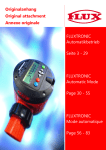
FLUXTRONIC
Normalbetrieb
Seite 3 - 23
FLUXTRONIC
Normal Mode
Page 24 - 44
FLUXTRONIC
Mode normal
Page 45 - 65
DEUTSCH
Originalanhang
Original attachment
Annexe originale
Achtung
Lesen Sie die Betriebsanleitung für Flüssigkeits-Mengenmesser und die
produkt-spezifischen Anhänge, bevor Sie das Gerät in Betrieb nehmen!
Attention
Read the main operating instructions for flow meters and the included
product-specific attachments before operating the device!
Attention
Lisez la notice d‘instructions générale pour les compteurs volumétriques
ainsi que les annexes spécifiques aux produits avant de mettre l’équipement
en service !
2 / 68
Anhang FLUXTRONIC Normalbetrieb
1
Sicherheit
1.1
Bestimmungsgemäße Verwendung
DEUTSCH
Flüssigkeits-Mengenmesser dienen dem komfortablen Messen von Flüssigkeiten.
Mengenmesser nicht der Witterung aussetzen.
Minimale und maximale Temperaturen beachten.
Maximalen Betriebsdruck beachten.
Nur saubere Flüssigkeiten verwenden.
1.2
Vorhersehbarer Missbrauch
Vorsicht!
• Das Gerät darf nur für die vom Hersteller angegebenen Zwecke
verwendet werden. Unzulässige Änderungen und die Verwendung von Ersatzteilen und Zubehör, die nicht vom Hersteller des
Geräts vertrieben oder empfohlen werden, können unter Umständen Sachschäden und Verletzungen verursachen.
• Kinder und andere unbefugte Personen dürfen keinen Zugang
oder Zugriff zu dem Gerät haben.
1.3
Sicherheitshinweise
Alle Sicherheitshinweise müssen beachtet und befolgt werden.
Das Nichtbeachten der Sicherheitshinweise kann das Leben und die Gesundheit von
Personen gefährden, zu Umweltschäden und/oder zu umfangreichen Sachschäden
führen.
Die Beachtung der Sicherheitshinweise in der Betriebsanleitung hilft, Gefahren zu vermeiden und den vollen Produktnutzen zu sichern.
Sicherheitshinweise zu den Tätigkeiten sind am Anfang des jeweiligen Kapitels aufgeführt.
Spezielle Sicherheitshinweise zu einzelnen Handlungsschritten stehen bei dem entsprechenden Handlungsschritt.
Achtung!
• Stellen Sie sicher, dass der Bediener die Bedienungsanleitung
gelesen und verstanden hat.
Gefahr!
Vergiftungsgefahr durch gesundheitsschädliche Stoffe / Dämpfe
> Nehmen Sie verschüttete gesundheitsschädliche Stoffe sofort
auf.
> Essen oder trinken Sie nie beim Abfüllen gesundheitsschädlicher
Flüssigkeiten
Anhang FLUXTRONIC Normalbetrieb
3 / 68
Achtung!
Gefahr durch Verspritzen der Flüssigkeit!
DEUTSCH
•
•
•
Maximalen Betriebsdruck und die Betriebstemperatur beachten.
Bei hohem Betriebsdruck können Behälter und Schläuche platzen oder sich lösen. Sorgen Sie dafür, dass es beim Einfüllen in
einen Behälter nicht zu einem Überdruck kommt.
Vorsichtig und mit angemessener Geschwindigkeit abfüllen, um
ein Herausspritzen der Flüssigkeiten zu verhindern.
Vorsicht!
• Melden Sie Fehler am Gerät sofort dem zuständigen Vorgesetzten.
Vorsicht!
Verletzungsgefahr!
• Betriebsinterne Anweisungen beachten.
• Schutzkleidung tragen.
(Gesichts- und Atemschutz, Schutzhandschuhe usw.)
Achtung Materialschäden!
Sind die Werkstoffe des Mengenmessers gegenüber der zu fördernden Flüssigkeit nicht beständig, dürfen diese nicht verwendet werden.
• Beständigkeit und betriebsinterne Anweisungen beachten.
Information
Defekte Teile sind grundsätzlich zu ersetzen.
Verwenden Sie Originalersatzteile.
Beim Einschicken von Komponenten zur Reparatur muss die
Dekontaminationsbescheinigung beigelegt werden (Download
unter www.flux-pumpen.de).
4 / 68
Anhang FLUXTRONIC Normalbetrieb
Sicherheitshinweise bei Verwendung der FLUXTRONIC im
explosionsgefährdeten Bereich
DEUTSCH
1.4
Die Zulassungsbescheinigungen und Bedienungsanleitungen aller
im Ex-Bereich eingesetzten Geräte beachten.
Elektrostatische Aufladung bei der Installation und beim Betrieb
vermeiden.
Nur mit einem wasserfeuchten Tuch reinigen.
Nur außerhalb des explosionsgefährdeten Bereiches reinigen.
Batterie nur außerhalb des explosionsgefährdeten Bereiches
wechseln.
Im Ex-Bereich nur mit Batterie betreiben.
Zum Batteriewechsel muss die Anzeigeelektronik abmontiert
werden.
Hinweise für den Transport im Ex-geschützten Bereich:
Elektrostatische Aufladung beim Transport vermeiden.
Interne Betriebsanweisungen beachten.
Beachten Sie bei der Installation und beim Betrieb die TRbF
(Technische-Richtlinien „brennbare Flüssigkeiten“) und die
Explosionsschutz-Richtlinien der BG Chemie.
1.5
Sicherheitshinweise bei Verwendung der Impulsweiterleitung im
Ex-Bereich
Der Einsatz der FLUXTRONIC im Ex-Bereich macht es notwendig, eine Signalschnittstelle zu wählen, die im Ex-Bereich zugelassen ist. Dies ist nicht bei allen
erhältlichen Schaltverstärkern der Fall. Die NAMUR*-Schnittstelle ist bewährt und
vereint alle oben genannten Forderungen.
Um dieses Signal nutzen zu können, ist ein Trennschaltverstärker mit NAMUR
Eingang notwendig, der bis mindestens 200 Hz schalten kann.
Wenn Sie eigene Schaltverstärker benutzen, beachten Sie unbedingt die Zulassungsbescheinigungen der Anzeigeelektronik und
der von Ihnen verwendeten Schaltverstärker.
(* NAMUR = Normen Ausschuss Mess- und Regeltechnik)
Anhang FLUXTRONIC Normalbetrieb
5 / 68
Der Schaltverstärker und die damit verbundenen externen Geräte
dürfen nur von sachkundigen Personen eingebaut, betrieben und
gewartet werden.
DEUTSCH
Die Stromversorgung darf nur eingeschaltet werden, wenn die Geräte eingebaut sind und spannungsführende Teile nicht berührt
werden können.
Gefahr!
Lebensgefahr durch Berühren spannungsführender Teile.
> Halten Sie Schaltschränke stets verschlossen.
> Führen Sie keine Arbeiten an spannungsführenden Teilen aus.
> Wechseln Sie lose Verbindungen, beschädigte, angeschmorte
oder durchgeschmorte Kabel sofort aus. Führen Sie Arbeiten nur
bei ausgeschaltetem und abgeschlossenem Hauptschalter durch.
> Vergewissern Sie sich, dass keine Kabel eingeklemmt bzw. gequetscht werden. Vergewissern Sie sich, dass die Kabel so verlegt sind, dass sie keine Stolperfallen bilden oder beschädigt
werden können.
> Alle Arbeiten dürfen nur von dafür ausgebildeten und an der Anlage unterwiesenen Fachkräften ausgeführt werden.
> Der Zugang zu den Schaltschränken ist nur dem autorisierten
Personal mit Schlüssel oder Werkzeug erlaubt.
> Wir empfehlen die Spannungsversorgung in Feuchträumen mit
FI-Schutzschalter auszustatten.
> Die Stromversorgung darf nur eingeschaltet werden, wenn die
Geräte eingebaut sind und spannungsführende Teile nicht berührt werden können.
Wenn sich der Schaltverstärker und die FLUXTRONIC im ExBereich (Zone 1) befinden, dürfen nur zugelassene Schaltverstärker (Kategorie 2) verwendet werden.
Wenn sich der Schaltverstärker außerhalb des Ex-Bereiches
und die FLUXTRONIC im Ex-Bereich (Zone 1) befinden, dürfen
nur zugelassene Schaltverstärker mit einem Steuerkreis (Kategorie
2) verwendet werden.
6 / 68
Anhang FLUXTRONIC Normalbetrieb
FLUXTRONIC
Die FLUXTRONIC zeigt die Flüssigkeitsmenge an, die durch einen FlüssigkeitsMengenmesser geflossen ist.
Der Taumelscheibenzähler erzeugt volumenabhängige Impulse (z.B. 0,05 L/Impuls).
Die Impulse werden von der FLUXTRONIC registriert und über eine Kalibrierkonstante
in das eigentliche Volumen umgerechnet.
Anzahl Impulse x Kalibrierkonstante = Volumen.
Die Elektronik kann in zwei verschiedenen Betriebsarten verwendet werden.
Betriebsart 1: Der Normalbetrieb
Im Normalbetrieb wird das Volumen, das durch einen Flüssigkeitsmengenmesser
geflossen ist, angezeigt.
Anzeige
Einheitenblock
Infozeile
Abbruch
Bearbeiten
OK
Links / Rechts
Auf / Ab
Organische Lösemittel von der Tastatur und der LCD Anzeige
fernhalten.
Anhang FLUXTRONIC Normalbetrieb
7 / 68
DEUTSCH
2
2.1
Die Bedienung der FLUXTRONIC
DEUTSCH
Die FLUXTRONIC beinhaltet fünf Menübereiche.
Zwischen den Menübereichen kann jederzeit durch die Auf- und Ab-Taste umgeschaltet werden. Angezeigt wird der für das jeweilige Menü entscheidende Wert.
Die einzelnen Menüpunkte sind:
1. BC RUN:
2. TOT:
3. FLO:
4. CAL 0:
5. SET:
Die Abfüllmenge wird angezeigt
Die Totalmenge wird angezeigt
Der Durchfluss wird angezeigt
Die aktuelle Kalibrierkonstante wird angezeigt
Allgemeine Einstellungen
1 Standardanzeige
5
RUN
TOT
SET
4
2.2
CAL
FLO
2
3
bearbeiten
abbrechen
Das Bedienkonzept
Alle Einstellungen werden durch folgendes Bedienkonzept durchgeführt.
RUN
Bearbeiten
Auswählen
(links/rechts
auf/ab)
Bearbeiten
Ausführen
Standardanzeige
Durch die Rückmeldung in der Infozeile und durch blinkende Symbole werden die
aktuellen und möglichen Einstellungen schnell erkannt.
8 / 68
Anhang FLUXTRONIC Normalbetrieb
Allgemeines
Die Abbruch-Taste kann jederzeit gedrückt werden und wird deshalb
auch nicht dargestellt.
Bei jedem Tastendruck wird ein Schritt zurück gesprungen.
Wird dieses Symbol im Display dargestellt, muss zur Bearbeitung zuerst die
PIN eingegeben werden.
Einstellung in der [SET]-Gruppe Kapitel 5 -> PIN-Nr. (5.1) und Sicherheitsstufe (5.2)
Wird dieses Symbol im Display dargestellt, ist die Bearbeitung zugelassen.
Werden Impulse am Eingang festgestellt, blinkt dieses Symbol auf.
Werden 5 Minuten lang weder Impulse gemessen noch irgendwelche Tasten bedient, wird das Display abgeschaltet. Sobald ein
Impuls festgestellt oder eine Taste bedient wird, schaltet sich das
Display wieder ein.
Solange Impulse gemessen werden, kann nicht bearbeitet werden und der SET
Bereich wird nicht dargestellt. Eine Sekunde, nachdem der letzte Impuls gemessen
wurde, kann wieder bearbeitet werden, und der SET-Bereich ist wieder erreichbar.
Werden während der Bearbeitung in einer Gruppe eine Minute lang keine Eingaben
gemacht, wird automatisch auf RUN umgeschaltet.
PIN vergessen?
Zurücksetzen des Sicherheitslevel [LOC] auf 0 und
Zurücksetzen der PIN-Nummer auf “000“
Alle sonstigen Einstellungen bleiben erhalten.
1. Batterie aus dem Batteriefach entfernen.
2. Vor dem Einsetzen der Batterie die Abbruch Taste drücken und gedrückt halten,
während die Batterie wieder eingesetzt wird.
Wenn die Kapazität der Batterie fast verbraucht ist, wird in der Infozeile
„LOW BATT“ abwechselnd mit der aktuellen Zeile dargestellt. Ist dies der Fall, kann die
Elektronik noch bis zu 2 Wochen normal weiterarbeiten.
Ist die Batteriekapazität soweit erschöpft, dass kein sicherer Ablauf mehr gewährleistet
werden kann, ist in der Anzeige nur noch „LOW BATT“ zu sehen und die Funktionen
werden nicht mehr ausgeführt.
Softwareversion
Die aktuell verwendete Version wird bei [SET]->[INFO]->[01] angezeigt.
Anhang FLUXTRONIC Normalbetrieb
9 / 68
DEUTSCH
3
3.1
Menü im Normalbetrieb
DEUTSCH
Menü
Kapitel
1 [RUN]
Standardanzeige im Normalbetrieb
2 [TOT]
3 [FLO]
4 [CAL]
5 [SET]
Aktion
Werte
7-stellig
1.1
Mengenanzeige
sofort löschen
1.2 [DEL]
Mengenanzeige
löschen
1.3 [DEC]
Dezimalstelle der Anzeige
ändern
Anzeige und Einstellungen der Totalmenge
0, 1, 2, 3
7-stellig
2.1 [DEL]
Totalmengenanzeige
löschen
2.2 [DEC]
Dezimalstelle der Anzeige
ändern
Anzeige und Einstellungen Durchfluss
0, 1, 2, 3
7-stellig
3.1 [UNIT]
Zeiteinheit der Durchflussanzeige
ändern
s, min, h
3.2 [DEC]
Dezimalstelle der Anzeige
ändern
0, 1, 2, 3
3.3 [GATE]
Torzeit zur Durchflussermittlung
ändern
0,0 s [OFF] bis
25,0 s
Anzeige und Einstellungen der Kalibrierung
4.1 [CAL]
Speicherplatz der Kalibrierkonstanten
auswählen
0 ... 9
4.2 [SET]
Kalibrierkonstante
ändern
7-stellig
4.3 [UNIT]
Mengeneinheit
ändern
[-], kg, g, m³, ml, L,
Imp GAL, US GAL
4.4 [DEC]
Dezimalstelle
ändern
0, 1, 2
Anzeige und Einstellungen verschiedener Betriebsparameter
5.1 [LOC]
Sicherheitsstufe
ändern
0, 1, 2, 3, 4
5.2 [PIN]
PIN-Nr.
ändern
000 ... 999
Impulsweiterleitung
ändern
ON <-> OFF
5.4 [DEF]
Defaultwerte
zurück-setzen
YES <-> NO
5.5 [INFO]
Informationen
anzeigen
01, 02, ...
5.3 [
10 / 68
Bezeichnung
]
Anhang FLUXTRONIC Normalbetrieb
Das Bedienkonzept
RUN
Bearbeiten
Auswählen
(links/rechts
auf/ab)
Bearbeiten
Ausführen
Standardanzeige
1. RUN
Standardanzeige
DEUTSCH
Alle Einstellungen werden durch folgendes Bedienkonzept durchgeführt.
Anzeigebereich: 9999.999 bis 9999999
Wird der jeweilige Anzeigebereich überschritten, wird das Komma verschoben, bis die
Maximalanzeige erreicht ist. Danach fängt der Zähler wieder bei 0 an zu zählen.
1.1 Mengenanzeige sofort löschen
Bei LOC 4 (Einstellung in der [SET]-Gruppe]) ist das sofortige Löschen der
Mengenanzeige nicht möglich. Zur Bearbeitung muss zuerst die PIN eingegeben werden
1.2 Mengenanzeige löschen [DEL]
1.3 Dezimalstelle ändern [DEC] 0 bis 3
Taste ~1 Sekunde drücken
1. RUN
Bearbeiten
1.1 Mengenanzeige
sofort löschen
Bearbeiten
1.2 Mengenanzeige
löschen [DEL]
Auswählen
3.2
Ausführen und
zurück zu [RUN]
Bearbeiten
Auswählen
1.3 Dezimalstelle
ändern [DEC]
0…3
Anhang FLUXTRONIC Normalbetrieb
11 / 68
2. TOT
Totalmengenanzeige
DEUTSCH
Anzeigebereich: 9999.999 bis 9999999
Wird der jeweilige Anzeigebereich überschritten, wird das Komma verschoben, bis die
Maximalanzeige erreicht ist. Danach fängt der Zähler wieder bei 0 an zu zählen.
2.1 Totalmenge löschen [DEL]
2.2 Dezimalstelle ändern [DEC] 0 bis 3
Bearbeiten
Auswählen
2. TOT
2.1 Totalmengenanzeige löschen
[DEL]
Bearbeiten
Ausführen
und zurück
zu [RUN]
Auswählen
Bearbeiten
2.2 Dezimalstelle
ändern [DEC]
0…3
12 / 68
Anhang FLUXTRONIC Normalbetrieb
3. FLO
Durchflussanzeige
Wird der jeweilige Anzeigebereich überschritten, wird das Komma verschoben, bis die
Maximalanzeige erreicht ist.
3.1
Die Zeiteinheit für die Durchflussanzeige ändern [UNIT] m (Minute), h (Stunde),
s (Sekunde).
3.2
Die Dezimalstelle ändern [DEC] 0 bis 3.
3.3
Die Torzeit ändern [GATE] 0,0 bis 25,0 Sekunden.
Die Elektronik misst die Anzahl von Impulsen, die in einem festgelegten Zeitabschnitt
ankommen. Dieser Zeitabschnitt ist die Torzeit [GATE].
Wird auf 0,0 s eingestellt, wird im Display OFF angezeigt.
Zusammen mit der Kalibrierkonstanten [CAL] und der festgelegten Zeiteinheit für die
Anzeige [UNIT] wird der Durchfluss berechnet.
Je länger die Torzeit gewählt wird, umso genauer wird die Anzeige, aber die
Aktualisierung der Anzeige verlangsamt sich entsprechend.
Bearbeiten
Auswählen
3.1 Zeiteinheit ändern [UNIT]
Auswählen
s, min, h
Bearbeiten
Auswählen
Ausführen
und zurück
zu [RUN]
3.2 Dezimalstelle
ändern [DEC]
0…3
Auswählen
3. FLO
Bearbeiten
Bearbeiten
Auswählen /
Einstellen
3.3 Torzeit ändern
[GATE]
0,0 [OFF] … 25,0 s
Anhang FLUXTRONIC Normalbetrieb
13 / 68
DEUTSCH
Anzeigebereich: 9999.999 bis 9999999.
4. CAL
Anzeige der Kalibrierkonstanten
Einstellbereich: 0.9999999 bis 99.99999
DEUTSCH
4.1
Den Speicherplatz der Kalibrierkonstanten auswählen [CAL] 0 bis 9.
Es gibt 10 Speicherplätze.
Auf jedem Speicherplatz können die Einstellungen von SET, UNIT und DEC unterschiedlich sein. Die angezeigte Einheit der Mengenanzeige der Totalmengenanzeige
und der Durchflussanzeige ist von der Einstellung bei [UNIT] der Kalibrierkonstanten
abhängig. Somit kann durch die Auswahl des Speicherplatzes nicht nur die Kalibrierung
geändert werden, sondern auch die Mengeneinheit.
4.2
Einstellen der Kalibrierkonstanten auf dem gewählten Speicherplatz [SET]
4.3
Einstellen der Mengeneinheit der Kalibrierkonstanten auf dem gewählten
Speicherplatz [UNIT]
4.4
Die Dezimalstelle der Kalibrierkonstanten auf dem gewählten Speicherplatz
einstellen [DEC]
Ausführen und
zurück zu [RUN]
Auswählen
Bearbeiten
4. CAL
4.1 Speicherplatz
ändern [CAL]
Auswählen/Einstellen
4.2 Kalibrierkonstante ändern
[SET]
Bearbeiten
7-stellig
Auswählen
Bearbeiten
Auswählen
4.3 Mengeneinheit ändern
[UNIT]
Ausführen und
zurück zu [RUN]
Bearbeiten
Auswählen
[-], kg, g, m³, mL, L,
lmp Gal, US Gal
Auswählen
Bearbeiten
4.4 Dezimalstelle
ändern [DEC]
0…3
Durch eine Änderung der Kalibrierkonstanten werden die Mengenanzeige und die
Totalmenge gelöscht.
14 / 68
Anhang FLUXTRONIC Normalbetrieb
5. SET
5.1
Sicherheitsstufe ändern [LOC]
Durch die Einstellung des LOC können die Bereiche vor unbeabsichtigten Änderungen
geschützt werden. Es gibt 5 Sicherheitsstufen, wobei „0“ keine Sicherheit und „4“ maximale Sicherheit bedeutet.
Bereich
LOC
RUN
TOT
FLO
CAL
SET
4
PIN
PIN
PIN
PIN
PIN
3
OK
PIN
PIN
PIN
PIN
2
OK
OK
PIN
PIN
PIN
1
OK
OK
OK
PIN
PIN
0
OK
OK
OK
OK
OK
5.2
PIN-Nummer ändern [PIN].
Ist die Sicherheitsstufe gewählt, kann noch eine 3-stellige PIN-Nummer vergeben werden. Diese PIN-Nummer muss dann jedes Mal eingegeben werden, wenn ein geschützter Bereich bearbeitet werden soll. Die PIN-Nummer kann auch „000“ sein.
PIN vergessen?
Nicht im Ex-Bereich!
Zurücksetzen des Sicherheitslevel [LOC] auf 0 und
Zurücksetzen der PIN-Nummer auf “000“
Alle sonstigen Einstellungen bleiben erhalten.
1.
Batterie aus dem Batteriefach entfernen.
2.
Vor dem Einsetzen der Batterie die Abbruch Taste drücken und gedrückt halten,
während die Batterie wieder eingesetzt wird.
Anhang FLUXTRONIC Normalbetrieb
15 / 68
DEUTSCH
Allgemeine Einstellungen.
5.3
Impulsweiterleitung ändern [
]
DEUTSCH
Die Impulsweiterleitung ist für andere Anwendungen oder Geräte vorgesehen, die den
Eingangsimpuls der Auswerteelektronik ebenfalls verarbeiten können. Der Eingangsimpuls wird von der Auswertelektronik bearbeitet und in ein Rechteckimpuls ohne Kontaktprellen umgewandelt und ausgegeben. Um dieses Signal nutzen zu können, ist ein
Trennschaltverstärker mit NAMUR Eingang notwendig, der bis zu 150 Hz schalten
kann.
5.4
Zurücksetzen aller Einstellungen auf Standardwerte [DEF]
Beim Zurücksetzen aller Einstellungen auf die Defaultwerte werden folgende
Einstellungen vorgenommen.
Bereich Bezeichnung
Aktion
RUN
Abfüllmenge
Wird gelöscht
RUN
Dezimalstelle [DEC]
1
TOT
Totalmenge
Wird gelöscht
TOT
Dezimalstelle [DEC]
0
FLO
Zeiteinheit [UNIT]
min
FLO
Dezimalstelle [DEC]
0
FLO
Torzeit [GATE]
3,0 s
CAL
Speicher [CAL]
0
CAL
Einstellwert [SET]
Alle Speicher auf 0,0500000
CAL
Einheit [UNIT]
Alle Speicher auf „L“
CAL
Dezimalstelle [DEC]
0
SET
Sicherheitslevel [LOC]
0
SET
PIN-Nummer [PIN]
000
SET
Impulsweiterleitung [
5.5
16 / 68
]
„OFF“
Information zur Softwareversion und sonstige Informationen
Nr.
Bezeichnung
01
aktuell verwendete Softwareversion
02
Anzahl, wie oft die Spannung ab- und wieder angeschaltet wurde
(z.B. Batteriewechsel)
Anhang FLUXTRONIC Normalbetrieb
Auswählen
5.1 Sicherheitsstufe ändern
[LOC]
Auswählen
0 …4
Bearbeiten
Ändern/Einstellen
5.2 PIN ändern
[PIN]
Auswählen
000 … 999
Bearbeiten Auswählen
Ausführen und
zurück zu [RUN]
5.3 Impulsweiterleitung
Auswählen
On / Off
5.4 Auf Standardwerte
zurücksetzen [DEF]
Bearbeiten
Auswählen
Yes / No
Auswählen
5. SET
Bearbeiten
DEUTSCH
Bearbeiten
Auswählen
5.5 Informationen ansehen [INFO]
Bearbeiten
01 Softwareversion
02 Batteriewechsel
Anhang FLUXTRONIC Normalbetrieb
17 / 68
4
Technische Daten
DEUTSCH
Ex-Kennzeichnung:
II 2 G Ex i a IIB T6 Gb
PTB 11 ATEX 2005
Elektrische Daten siehe
Zulassungsbescheinigung
Lagertemperatur -25°C bis max. +70°C
Umgebungstemperatur -20°C* bis max. +40°C
* Bei Temperaturen unter 0°C wird die LCD-Anzeige verlangsamt.
Werkstoff: Elektronikgehäuse PP; Display PSU; Blende PP
Batterie: Lithium CR 2032
Lebensdauer: je nach Verwendung 1 bis 2 Jahre
Sensoreingang: Mechanischer Kontakt
Frequenz max. 150 Hz bei Tastverhältnis 50/50
Impulsausgang: NAMUR Ausgang.
Zur Verwendung des Ausgangs ist ein NAMUR Trennschaltverstärker mit Transistor
Ein- und Ausgang notwendig
Frequenz max. 150 Hz bei Tastverhältnis 50/50
Belegung der 9-poligen Steckerleiste
PIN-Nr.
Farbe
Kurzbez.
Beschreibung
1
grün
IMP OUT
NAMUR Ausgang Impulsweiterleitung
6*1
grau
IMP IN
Eingang externe Impulse (Reedschalter).
Es wird mit + 3V (9) geschaltet.
8
weiß
GND
Minus-Anschluss für NAMUR-Ausgänge
(im Ex-Bereich nicht zugelassen)
9
braun + 3V
Plus-Anschluss für Eingänge 6 und 7
(im Ex-Bereich nicht zugelassen)
*1
Bei Verwendung des Eingangs für einen externen Sensor muss der Stecker des
eingebauten Sensors abgezogen werden.
Steckerbelegung bei 5-poliger Ausführung:
grün (1)
braun (9)
weiß (8)
grau (6)
Beim Kabel ist die Abschirmung auf „schwarz“ herausgeführt.
18 / 68
Anhang FLUXTRONIC Normalbetrieb
Beispiele:
Der Mengenmesser ist nur für die Verwendung im Normalbetrieb.
DEUTSCH
Wenn der Mengenmesser angeliefert wird, ist das Display abgeschaltet.
Durch einen Tastendruck wird das Display wieder eingeschaltet.
Durch mehrmaliges Drücken der Abbrechen-Taste stellt man sicher, dass auf
„RUN: Die Abfüllmenge wird angezeigt“ umgeschaltet ist.
1. Die Totalmenge soll mit einer Nachkommastelle angezeigt werden.
Wechseln mit der Ab-Taste auf „TOT: Die Totalmenge wird angezeigt“
Bearbeiten-Taste drücken.
Mit der Ab-Taste [DEC] auswählen.
Die Bearbeiten-Taste wieder drücken.
Mit der links-Taste den blinkenden Dezimalpunkt auf eine Nachkommastelle einstellen.
Die Ausführen-Taste drücken.
Jetzt befindet man sich wieder in „RUN: Die Abfüllmenge wird angezeigt“.
2. Die Mengeneinheit soll einmal in Liter und ein anderes Mal in Kilogramm dargestellt werden.
Die Mengeneinheit ist der Kalibrierkonstanten zugeordnet und wird deshalb in „CAL0: Die
aktuelle Kalibrierkonstante wird angezeigt“ eingestellt.
Im Auslieferungszustand ist hier auf Speicherplatz 0 eine Kalibrierkonstante eingestellt, die
im Werk durch Messung mit Wasser ermittelt wurde (z.B. .0498765 L/Imp).
Möchte man die Anzeige in kg haben, muss man entweder die Dichte der Flüssigkeit kennen und damit die Kalibrierkonstante von Liter/Impuls auf kg/Impuls umrechnen, oder man
benutzt eine Waage, um die Masse der abgefüllten Menge zu ermitteln.
Z.B. Die Dichte der Flüssigkeit ist 1,2 kg/L, also ist die neue Kalibrierkonstante
0.0498765L/Imp x 1,2 kg/L =0.0598518 kg/Imp.
Oder
Man füllt mit dem Mengenmesser z.B. in einen Eimer eine möglichst große Menge ab (z.B.
Anzeige auf dem Mengenmesser 25,4 Liter).
Auf der Waage kann man das Gewicht von 30,48 kg ablesen. Jetzt kennt man die Dichte
der Flüssigkeit = 30,48 kg / 25,4 Liter =1,2 kg/Liter.
Also wieder 0,0498765 L/Imp x 1,2 kg/L =0.0598518 kg/Imp
Die neue Kalibrierkonstante soll auf Speicherplatz 1 gespeichert werden.
Bei der Änderung der Kalibrierkonstanten werden die Anzeige der abgefüllten Menge und
die Totalmenge zurückgesetzt.
Wechseln mit der Ab-Taste auf die „CAL0: Die aktuelle Kalibrierkonstante wird angezeigt“.
Bearbeiten-Taste drücken.
Mit der Auf- oder Ab-Taste den Speicherplatz auf 1 einstellen.
Bearbeiten-Taste drücken.
Da man sich jetzt schon im [SET] Menüpunkt befindet, nochmals die Bearbeiten-Taste
drücken.
Anhang FLUXTRONIC Normalbetrieb
19 / 68
Mit den links/rechts Tasten die jeweilige Ziffer auswählen und mit den Auf/Ab-Tasten
den Wert der Ziffer einstellen.
.0598518
Die Ausführen-Taste drücken.
DEUTSCH
Jetzt befindet man sich wieder in „RUN: Die Abfüllmenge wird angezeigt“.
Um die Einheit einzustellen, wieder mit der Ab-Taste auf „CAL0: Die aktuelle Kalibrierkonstante wird angezeigt“ wechseln.
(CAL 1 / .0598518)
Die Bearbeiten-Taste drücken.
Der Speicherplatz bleibt auf 1.
Die Bearbeiten-Taste drücken.
Mit der Ab-Taste den Menüpunkt [UNIT] auswählen.
Die Bearbeiten-Taste drücken.
Mit der Auf- oder Ab-Taste auf Kilogramm einstellen.
Die Ausführen-Taste drücken.
Jetzt befindet man sich wieder in „RUN: Die Abfüllmenge wird angezeigt“.
Um jetzt wieder auf die Kalibrierkonstante auf Speicherplatz 0 (.0498765) mit der Einheit Liter umzuschalten, muss nur der Speicherplatz von 1 wieder auf 0 geändert werden.
Wechseln mit der Ab-Taste auf „CAL0: Die aktuelle Kalibrierkonstante wird angezeigt“.
Bearbeiten-Taste drücken.
Mit der Auf- oder Ab-Taste den Speicherplatz auf 0 einstellen.
Die Ausführen-Taste drücken.
Jetzt befindet man sich wieder in „RUN: Die Abfüllmenge wird angezeigt“.
Und zurück auf kg mit der Kalibrierkonstanten (.0598518)-->
Wieder Speicherplatz 1 wählen.
3. Der Benutzer darf die jeweils abgefüllte Menge löschen und auch die Dezimalstelle der Anzeige ändern, aber sonstige Einstellungen nicht verändern.
Dafür sind Einstellungen in „SET: Allgemeine Einstellungen“ vorzunehmen.
Im Kapitel 5.1 „Sicherheitsstufe ändern“ sieht man in der Tabelle, dass [LOC] Ebene 3
eingestellt werden soll. Alle Menübereiche außer RUN sind nur über die Eingabe der
PIN bearbeitbar.
Wechseln mit der Auf-Taste in „SET: Allgemeine Einstellungen“.
Bearbeiten-Taste drücken.
Da man sich jetzt schon im [LOC] Menüpunkt befindet, nochmals die Bearbeiten-Taste
drücken.
Mit der Auf- oder Ab-Taste die [LOC]-Ebene auf 3 einstellen.
Jetzt befindet man sich wieder in „RUN: Die Abfüllmenge wird angezeigt“.
20 / 68
Anhang FLUXTRONIC Normalbetrieb
Jetzt kann noch eine PIN festgelegt werden (Standard=“000“).
Wechseln mit der Auf-Taste in „SET: Allgemeine Einstellungen“
DEUTSCH
Bearbeiten-Taste drücken.
Die PIN ist noch „000“, also die Ausführen-Taste drücken.
Mit der Ab-Taste den Menüpunkt [PIN] auswählen.
Die Bearbeiten-Taste drücken.
Mit den links/rechts Tasten die jeweilige Ziffer auswählen und mit den Auf-Ab-Tasten
den Wert der Ziffer einstellen.
Die Ausführen-Taste drücken.
Jetzt befindet man sich wieder in „RUN: Die Abfüllmenge wird angezeigt“.
Ab jetzt sind die Menübereiche 2 bis 5 nur über die PIN bearbeitbar.
Anhang FLUXTRONIC Normalbetrieb
21 / 68
5
Austausch der FLUXTRONIC oder der Batterie
DEUTSCH
Batterie nur außerhalb des explosionsgefährdeten Bereichs
wechseln!
Die 4 Torx-Schrauben herausdrehen (Anzugsmoment max. 1,3 Nm).
Den Stecker vom Reed-Sensor aus der Elektronik ziehen.
Das Batteriefach mit einem geeigneten Werkzeug öffnen.
Beim Batteriewechsel gehen keine Daten verloren.
Batterie Lithium Knopfzelle CR 2032
22 / 68
Anhang FLUXTRONIC Normalbetrieb
6
Inbetriebnahme
DEUTSCH
Achtung Materialschäden!
Sind die Werkstoffe des Mengenmessers gegenüber der zu
fördernden Flüssigkeit nicht beständig, dürfen diese nicht verwendet
werden.
• Beständigkeit und betriebsinterne Anweisungen beachten.
Hinweis!
Beachten Sie die entsprechenden Sicherheitsdatenblätter der
abzufüllenden Stoffe.
Hinweis!
Defektes Signalkabel grundsätzlich ersetzen.
7
Betrieb
Der äußere Zustand des Mengenmessers muss durch regelmäßige Sichtkontrolle
überwacht werden.
8
Reparatur
Warnung!
Durch Verwendung nicht zugelassener Ersatzteile können Menschen
verletzt und die Maschine/Anlage beschädigt werden.
Verwenden Sie ausschließlich die vom Hersteller freigegebenen
Ersatz- und Verschleißteile.
>
System drucklos machen.
>
Pumpe vom Netz trennen
>
Rohrleitung, Schlauch, Mengenmesser und eventuell angeschlossene Armaturen
leer laufen lassen.
>
Defekte Teile grundsätzlich ersetzen.
>
Verwenden Sie Originalersatzteile.
Anhang FLUXTRONIC Normalbetrieb
23 / 68
1
Safety
1.1
Intended Use
Flow meters allow for convenient measuring of liquids.
Do not expose the flow meters to the weather.
Observe the minimum and maximum operating temperatures.
Observe the maximum operating pressure.
Only use clean liquids.
1.2
Foreseeable misuse
Caution!
• The device may only be used for the purposes given by the
manufacturer. Unauthorized changing and the use of spare parts
and accessories that are not sold or recommended by the manufacturer may cause damages or physical injuries.
• Children and other uninstructed persons should be supervised to
ensure that they do not play with the device.
ENGLISH
1.3
Safety instructions
All safety instructions must be observed and followed.
Failure to follow the safety instructions may lead to serious injury or death or cause environmental and/or property damage. Adherence to the safety instructions contained in
these operating instructions will help you to avoid risks, to operate the quick action tap
efficiently and to ensure that the product is used to its full potential.
Safety instructions on the activities are listed at the start of the respective chapter. Special safety instructions on individual action steps are given under the respective action
step.
Attention!
• Make sure that the operator has read and understood the
operating instructions.
Danger!
Danger of poisoning from harmful substances / vapours
> Take off spilled harmful substances.
> Never eat or drink when filling harmful liquids.
24 / 68
Attachment FLUXTRONIC normal mode
Attention!
Danger from splashing liquids!
•
•
•
The maximum operating pressure and operating temperature
must not be exceeded.
High operating pressure may result in the containers or the hoses bursting or becoming loose. Make sure that excessive pressure does not result when filling a container.
Fill carefully and at an appropriate speed to avoid leakage of the
liquid.
Caution!
•
Immediately inform the responsible supervisor about defects on
the device.
ENGLISH
Caution!
Risk of injury!
• Follow internal instructions.
• Wear protective clothing (face and breathing protection,
protective gloves, etc.).
Attention!
If the material of the flow meter is not resistant to the liquid to be
transferred, it must not be used.
• Observe the chemical resistance and internal instructions.
Note
Always replace defective parts.
Only use genuine spare parts.
When returning the pump for repair, it must be accompanied by the
decontamination certificate (download at www.flux-pumpen.de).
Attachment FLUXTRONIC normal mode
25 / 68
1.4
Safety information when using the FLUXTRONIC in explosion-risk areas
Please refer to the Certificates of acceptance and Operating
Manuals of all units used in explosion-risk areas.
Avoid electrostatic charges when installing and operating this
equipment.
Only clean with a damp cloth.
Only clean outside of the explosion-risk area.
Only change the battery outside of the explosion-risk area.
Only operate with a battery in explosion-risk areas.
Remove the electronic display unit when changing the battery.
Information when transporting in explosion-protected areas
ENGLISH
Avoid electrostatic charges when transporting.
• Note internal operating instructions.
Observe the Technical Guidelines for "Combustible Liquids"
and the German Institution for Statutory Accident Insurance
and Prevention in the Chemical Industry (BG Chemie) Explosion Protection Guidelines during installation and operation.
1.5
Using pulse redirection in explosion-risk areas:
The use of the FLUXTRONIC in areas at risk of explosion means that it is necessary to
select a signal interface permitted in areas at risk from explosion. The NAMUR* interface has proved itself in this respect. An isolating amplifier with a NAMUR input, capable of switching up to a minimum of 200 Hz, is needed to use this signal.
If you are using your own switching amplifier, it is imperative that
you note the certificates of conformity of the electronic analysis unit
and the switching amplifier you are using.
(* NAMUR = Normen Ausschuss Mess- und Regeltechnik)
The switching amplifier and the external units connected to it should
only be installed, operated and serviced by trained and qualified
personnel.
26 / 68
Attachment FLUXTRONIC normal mode
Danger!
Danger to life from touching live parts.
>
Always keep switching cabinets locked.
>
Do not undertake any work on live parts.
>
Change loose connections and any damaged, scorched or
burnt through cables immediately. Only undertake any work
when the main switch has been disconnected and shut off.
>
Ensure that no cables are trapped or squashed. Ensure that the
cables are laid in such a way that they do not lead to any trip
hazards or can be damaged.
>
All work may only be undertaken by skilled personnel who have
been instructed and trained on the system.
>
Only authorised personnel with a key or tool are allowed to
access the switching cabinets.
>
We recommend that the power supply is fitted with an FI safety
switch in damp areas.
>
Power should only be switched on once the equipment has
been installed and live parts cannot be touched.
If the switching amplifier and FLUXTRONIC are located in an
explosion-risk area (zone 1) only approved switching amplifiers
(category 2) should be used.
If the switching amplifier is located outside of the explosionrisk area and the FLUXTRONIC in the explosion-risk area (zone
1) only approved switching amplifiers with a control circuit (category
2) should be used.
Attachment FLUXTRONIC normal mode
27 / 68
ENGLISH
Power should only be switched on once the units have been installed and live parts cannot be touched.
2
FLUXTRONIC
The electronic analysis unit FLUXTRONIC displays the volume of liquid that has flown
through a flow meter.
The nutating disc meter generates pulses by volume (e.g. 0.05 L/pulse). The pulses are
registered by the electronic analysis unit and converted into the actual volume via a calibration constant.
Number of pulses x Calibration constant = Volume.
The electronic unit can be used in two different operating modes:
Operating mode 1: Normal mode
In Normal mode the volume that flows through a flow meter is displayed.
Display
Unit block
ENGLISH
Information line
Stop
Process
OK
left/right
up/down
Keep organic solvents away from the keyboard and LCD display.
28 / 68
Attachment FLUXTRONIC normal mode
2.1
Operating the FLUXTRONIC
The FLUXTRONIC contains five menu items.
The user can switch between the items at any time using the Up and Down keys.
The key figure for each respective item is displayed.
1. BC RUN: The volume to be filled is displayed
2. TOT: The total volume is displayed
3. FLO: The flow rate is displayed
4. CAL 0: The current calibration constant is displayed
5. SET: General settings
1 Default display
TOT
SET
4
2.2
CAL
FLO
2
3
Process
ENGLISH
RUN
5
Stop
The Operating Concept
All of the settings are inputted using the following operating concept.
RUN
Process
Select
(left/right
up/down)
Process
Operate
Default display
The current and possible settings can be quickly seen by feedback in the Info line and
by the flashing symbols.
Attachment FLUXTRONIC normal mode
29 / 68
3
General Information
The Stop key can be pressed at any time and is not shown for this reason.
Pressing the key once moves you back one step.
If this symbol appears on the display, the PIN must firstly be entered
before processing.
For setting, refer to the [SET] group in chapter 5 -> Security Level (5.1) and
PIN No. (5.2)
Operation of the unit is permitted when this symbol is shown on the
display.
This symbol flashes if pulses are detected at the input.
The display is switched off if no pulse is measured or if no key is
pressed for 5 minutes. The display switches on again as soon as a pulse
is detected or a key pressed.
ENGLISH
The unit cannot be operated when pulses can still be measured and the SET range
is not displayed. The unit can be operated one second after the last pulse was measured and the SET range can be accessed again.
If no entries are made during operating in a group for one minute, the unit automatically
switches over to [RUN].
Forgotten your PIN?
Reset security level [LOC] to 0 and
Reset PIN number to "000"
All other entries are retained.
1. Remove battery from the battery compartment.
2. Press the Stop key before inserting the battery and hold it down while it is being inserted.
When the battery capacity is almost empty, the information line shows
"LOW BATT" alternatively with the current line. When this is the case, the electronic unit
can run normally for up to 2 weeks.
When the battery capacity is so low that processing can no longer be reliably guaranteed, the display only shows "LOW BATT" and the functions are no longer executed.
Software version
The version currently used is shown at [SET]->[INFO]->[01].
30 / 68
Attachment FLUXTRONIC normal mode
Menu in normal mode
Menu
Chapter
1 [RUN]
Default display in normal mode
2 [TOT]
3 [FLO]
4 [CAL]
5 [SET]
Designation
Action
Figures
7-digit
1.1
Volume display
delete immediately
1.2 [DEL]
Volume display
delete
1.3 [DEC]
Decimal place of display
change
Total volume display and settings
0, 1, 2, 3
7-digit
2.1 [DEL]
Display of total volume
delete
2.2 [DEC]
Decimal place of display
change
Flowrate display and settings
0, 1, 2, 3
7-digit
3.1 [UNIT]
Time unit of flow rate display
change
s, min, h
3.2 [DEC]
Decimal place of display
change
0, 1, 2, 3
3.3 [GATE]
Gate time for determining
flow rate
change
0.0 s [OFF] to 25.0 s
4.1 [CAL]
Memory location for calibration constants
select
0 ... 9
4.2 [SET]
Calibration constant
change
7-digit
4.3 [UNIT]
Unit of volume
change
[-], kg, g, m³, ml, L,
Imp GAL, US GAL
4.4 [DEC]
Decimal place
change
0, 1, 2
Calibration display and settings
Display and settings of different operating parameters
5.1 [LOC]
Security level
change
0, 1, 2, 3, 4
5.2 [PIN]
PIN no.
change
000 ... 999
Pulse redirection
change
On <-> Off
5.4 [DEF]
Default values
reset
YES <-> NO
5.5 [INFO]
Information
display
01, 02, ...
5.3 [
]
Attachment FLUXTRONIC normal mode
31 / 68
ENGLISH
3.1
3.2
The Operating Concept
All of the settings are inputted using the following operating concept.
RUN
Process
Select
(left/right
up/down)
Process
Operate
Default display
1. RUN
Default display
Display range: 9999.999 to 9999999
The point is moved when the respective display range is exceeded until the maximum
display is reached. The counter then starts counting again at 0.
ENGLISH
1.1 Immediately delete volume display
With LOC 4 (setting in [SET]) it is not possible to delete the volume display
immediately. For processing, first enter the PIN.
1.2 Delete volume display [DEL]
1.3 Change decimal place [DEC] 0 to 3.
Press key for ~ 1 second
1. RUN
Process
1.1 Immediately delete
volume display
Process
Operate
and back
to [RUN]
Select
1.2 Delete volume
display [DEL]
1.3 Change decimal
place [DEC]
Process
Select
0…3
32 / 68
Attachment FLUXTRONIC normal mode
2. TOT
Display of total volume
Display range: 9999.999 to 9999999
The point is moved when the respective display range is exceeded until the maximum
display is reached. The counter then starts counting again at 0.
2.1 Delete total volume [DEL]
2.2 Change decimal place [DEC] 0 to 3
Process
Process
Operate and
back to [RUN]
Select
Process
Select
ENGLISH
2. TOT
2.1 Delete display of
total volume [DEL]
2.2 Change decimal
place [DEC]
0…3
Attachment FLUXTRONIC normal mode
33 / 68
3. FLO
Display of flow rate
Display range: 9999.999 to 9999999.
The point is moved when the respective display range is exceeded until the maximum
display is reached.
3.1 Change the time unit for the flow rate display [UNIT] m (minute), h (hour),
s (second).
3.2 Change the decimal place [DEC] 0 to 3.
3.3 Change the gate time [GATE] 0.0 to 25.0 seconds.
The electronic unit measures the number of pulses that occur during a defined period of
time. This period of time is known as the gate time [GATE].
The display shows OFF if it is set to 0.0 s.
The flow rate is calculated together with the calibration constant [CAL] and the defined
time unit for the display [UNIT].
ENGLISH
The longer the gate time selected, the more precise will be the display although the updating of the display will slow down accordingly.
Process
3. FLO
Process
Select
3.1 Change time unit
[UNIT]
Select
s, min, h
3.2 Change decimal
place [DEC]
Operate and
back to [RUN]
Process
Select
Select
0…3
Process
Select
3.3 Change gate time
[GATE]
0,0 [OFF] … 25,0 s
34 / 68
Attachment FLUXTRONIC normal mode
4. CAL
Display of calibration constants
Setting range: 0.9999999 to 99.99999
4.1 Select the memory location of the calibration constants [CAL] 0 to 9
There are 10 memory locations.
The settings of SET, UNIT and DEC can vary at each memory location. The displayed
unit of volume of the total volume display and the flow rate display depends on the setting of the calibration constants at [UNIT]. This means that not only can the calibration
be changed by the selection of the memory location but also the volume unit.
4.2 Set the calibration constants at the selected memory location [SET]
4.3 Set the volume unit of the calibration constants at the selected memory location
[UNIT]
4.4 Set the decimal place of the calibration constants at the selected memory location
[DEC].
ENGLISH
Operate and back to [RUN]
Select
Process
4.1 Change
memory location
4. CAL
Select/Enter
Process
4.2 Change calibration constant [SET]
Process
Select
7-digit
Select
4.3 Change volume
unit [UNIT]
Operate and back
to [RUN]
Process
Select
[-], kg, g, m³, mL, L,
lmp Gal, US Gal
Select
4.4 Change decimal
place [DEC]
Process
0…3
The volume display and the total volume are deleted by changing the calibration
constants.
Attachment FLUXTRONIC normal mode
35 / 68
5. SET
General settings
5.1 Change security level [LOC]
The LOC setting can be used to protect the ranges from inadvertent changes. There
are 5 security levels, "0" meaning no security and "4" meaning maximum security.
Bereich
LOC
RUN
TOT
FLO
CAL
SET
4
PIN
PIN
PIN
PIN
PIN
3
OK
PIN
PIN
PIN
PIN
2
OK
OK
PIN
PIN
PIN
1
OK
OK
OK
PIN
PIN
0
OK
OK
OK
OK
OK
ENGLISH
5.2 Change PIN number [PIN].
A 3-digit PIN number can be issued once the security level has been selected. This PIN
number must then be entered each time that a protected range is processed. The PIN
number can also be "000".
Forgotten your PIN?
Not in explosion-risk areas!
Reset security level [LOC] to 0 and
Reset PIN number to "000"
All other entries are retained.
1. Remove battery from the battery compartment.
2. Press the Stop key before inserting the battery and hold it down while it is being
inserted.
36 / 68
Attachment FLUXTRONIC normal mode
5.3 Change pulse redirection [
]
Pulse redirection is intended for other applications or units that can also process the
input pulse from the electronic analysis unit. The input pulse is processed by the electronic analysis unit and converted into a rectangular pulse without contact bounce and
then emitted. An isolating amplifier with a NAMUR input, capable of switching up to
150 Hz, is needed to use this signal.
5.4 Reset all settings to default values [DEF]
Area
Designation
Action
RUN
Volume to be filled
Deleted
RUN
Decimal place [DEC]
1
TOT
Total volume
Deleted
TOT
Decimal place [DEC]
0
FLO
Time unit [UNIT]
min
FLO
Decimal place [DEC]
0
FLO
Gate time [GATE]
3.0 s
CAL
Memory [CAL]
0
CAL
Setting value [SET]
All memories to 0.0500000
CAL
Unit [UNIT]
All memories to "L"
CAL
Decimal place [DEC]
0
SET
Security level [LOC]
0
SET
PIN number [PIN]
000
SET
Pulse redirection [
]
ENGLISH
The following settings are entered when all settings are reset to default values:
"OFF“
5.5 Information on software version and other information.
No.
Designation
01
Software version currently used
02
Number of times the voltage has been switched off and on (e.g.
battery change)
Attachment FLUXTRONIC normal mode
37 / 68
Process
5. SET
5.1 Change
security level
[LOC]
Process
Select
Select
0 …4
Process
Select/Enter
5.2 Change Pin
[PIN]
Select
000 … 999
Process
Select
5.3 Pulse redirection
ENGLISH
Select
On / Off
5.4 Reset to
default values
[DEF]
Process
Select
Select
Yes / No
Select
5.5 View information [INFO]
Process
01 Software version
02 Battery change
38 / 68
Attachment FLUXTRONIC normal mode
Operate and
back to [RUN]
Technical data
Explosion protection marking:
II 2 G Ex i a IIB T6 Gb
PTB 11 ATEX 2005
Electrical Data see
Certificate of Acceptance
Storage temperature -25°C up to max. +70°C
Surrounding temperature -20°C* up to max. +40°C
*At temperatures below 0°C the LCD display is slowed down.
Material: Electronic unit housing PP; Display PSU; Panel PP
Battery: Lithium CR 2032
Service life: 1 to 2 years, depending on use
Sensor input: Mechanical contact
Frequency max. 150 Hz with key ratio of 50/50
Pulse output: NAMUR output.
A NAMUR isolating amplifier with an input and output transistor is needed to use the
output.
Frequency max. 150 Hz with key ratio of 50/50
Assignment of the 9-pin contact strip
PIN No. Colour Short description
Description
1
NAMUR Exit pulse redirection
Green IMP OUT
6*1
Grey IMP IN
Input external pulses (Reed switch)
It is switched with +3V (9).
8
White GND
Minus connection (for NAMUR exits)
[Not permitted in explosion-proof areas]
9
Brown + 3 V
Plus connection (for entries 6 and 7)
[Not permitted in explosion-proof areas]
*1
When using the input for an external sensor the plug of the integrated sensor has to
be unplugged.
Assignment of the 5-pin version
green (4)
brown (9)
white (8)
grey (6)
The shielding is lead through on „black“ at the cable.
Attachment FLUXTRONIC normal mode
39 / 68
ENGLISH
4
Examples:
The flow meter is only suitable for use in normal mode.
The display is switched off when the flow meter is delivered.
The display can be switched on again by pressing a key.
By pressing the Stop key several times, the user can ensure that the unit has changed
over to "RUN: Filling volume is displayed".
1. The total volume should be displayed with a decimal place.
Use the Down key to switch to "TOT: The total volume is displayed"
Press Process key.
Select using the Down key [DEC].
Press Process key again.
Use the left key to set the flashing decimal point to one decimal place.
Press the Operate key.
The display is now in "RUN: The filling volume is displayed".
ENGLISH
2. The volume unit is to be shown once in litres and another time in kilograms.
The volume unit is assigned to the calibration constant and is therefore set in
"CAL0: The current calibration constant is displayed".
When delivered, a calibration constant is set at memory location 0, that was determined
in the factory using water (e.g. .0498765 L/pulse).
If the display is to show kg, either the density of the liquid must be known so that the
calibration constant can be converted from litre/pulse to kg/pulse, or weighing scales
are used to determine the mass of the volume filled.
For example the density of the liquid is 1.2 kg/L, therefore the new calibration constant
is 0.0498765 L/pulse x 1.2 kg/L =0.0598518 kg/pulse.
Or
Use the flow meter to fill a sufficiently large volume into a bucket, for instance (display
on the flow meter shows 25.4 litres). The weight of 30.48 kg can be read on the scales.
The density of the liquid is now known to be = 30.48 kg/ 25.4 litre =1.2 kg/litre.
Therefore again 0.0498765 L/pulse x 1.2 kg/L =0.0598518 kg/pulse
The new calibration constant is to be saved at memory location 1.
When the calibration constants are changed, the display of the volume filled and the
total volume is reset.
Use the Down key to switch to "CAL0: The current calibration constant is displayed".
Press Process key.
Use the Up or Down key to set the memory location to 1.
40 / 68
Attachment FLUXTRONIC normal mode
Press Process key.
As you are now in the [SET] menu item, press the Process key again.
Using the left/right keys, select the relevant digit and enter the value of the digit using
the Up/Down keys.
.0598518
Press the Operate key.
The display is now in "RUN: The filling volume is displayed".
To adjust the unit, use the Down key to change to "CAL0: The current calibration constant is displayed".
(CAL 1 / .0598518)
Press the Process key.
The memory location remains at 1.
Press the Process key.
Select using the [UNIT] menu item using the Down key.
Press the Process key.
Use the Up or Down key to set to "Kilogram".
The display is now in "RUN: The filling volume is displayed".
To now switch to the calibration constant at memory location 0 (.0498765) with the Litre
unit, change the memory location now from 1 to 0.
Use the Down key to switch to "CAL0: The current calibration constant is displayed".
Press Process key.
Use the Up or Down key to set the memory location to 0.
Press the Operate key.
The display is now in "RUN: The volume to be filled is displayed".
And back to kg with the calibration constant (.0598518) -->
Select memory location 1 again.
3. The user can delete the volume filled and also change the decimal place in the
display but cannot change the other settings.
To do so, enter settings in " SET: General Settings".
In chapter 5.1 "Change security level", the table shows that [LOC] Level 3 should be
set. All groups with the exception of RUN can only be processed by entering the PIN.
Use the Up key to switch to "SET: General Settings".
Press Process key.
As you are now in the [LOC] menu item, press the Process key again.
Use the Up or Down key to set the [LOC] level to 3.
Attachment FLUXTRONIC normal mode
41 / 68
ENGLISH
Press the Operate key.
The display is now again in "RUN: The volume to be filled is displayed".
A PIN can now be defined (default = "000").
Use the Up key to switch to "SET: General Settings"
Press Process key.
The PIN is still "000", therefore press Operate.
Select the [PIN] menu item using the Down key.
Press the Process key.
Using the left/right keys, select the relevant digit and enter the value of the digit using
the Up/Down keys.
Press the Operate key.
The display is now in "RUN: The volume to be filled is displayed".
From now on, items 2 to 5 can only be processed via the PIN
ENGLISH
42 / 68
Attachment FLUXTRONIC normal mode
Change of FLUXTRONIC or battery
Change battery only outside the explosion risk area!
Unscrew the four Torx screws (torque max. 1.3 Nm)
ENGLISH
5
Pull the plug of the reed sensor out of the electronic unit
Open the battery compartment using an appropriate tool.
No data is lost when the battery is changed.
Lithium round cell battery CR 2032
Attachment FLUXTRONIC normal mode
43 / 68
6
Commissioning
Attention!
If the material of the flow meter is not resistant to the liquid
to be transferred, it must not be used.
• Observe the chemical resistance and internal operating
instructions.
Note!
Check if the materials of the flow meter are appropriate for the
applications.
Note!
Generally replace a defect signalling cable.
ENGLISH
7
In operation
Regularly check the flow meter for function.
8
Repair
Warning!
When non-approved spare-parts are used persons can be hurt and
the machine/equipment can be damaged.
Only use spare and wear parts that are approved by the manufacturer.
44 / 68
>
Depressurise the system.
>
Separate pump from current.
>
Empty hose, flow meter and valves.
>
Always replace defective parts.
>
Only use genuine spare parts
Attachment FLUXTRONIC normal mode
1
Sécurité
1.1
Usage normal de l’équipement de travail
Les compteurs volumétriques sont conçus pour permettre un conditionnement aisé
de liquides.
Les compteurs volumétriques ne doivent pas être exposés aux intempéries.
Respecter les températures de service minimales et maximales.
Respecter la pression de service maximale.
Utiliser les compteurs uniquement avec des liquides propres.
1.2
Contre-indications d’utilisation
Attention!
• L’appareil ne doit être utilisé que pour l’usage indiqué par le
fabricant. Toute modification non autorisée ainsi que l’utilisation
de pièces de rechange et d’accessoires non commercialisés ou
non recommandés par le fabricant peuvent occasionner le cas
échéant des dommages matériels et des blessures.
• Les enfants doivent être surveillés pour être sûr qu'ils ne jouent
pas avec l'équipement.
Consignes de sécurité
Toutes les consignes de sécurité doivent être respectées.
Le non-respect des consignes de sécurité peut mettre la vie des personnes en danger,
causer des dommages à l'environnement et/ou causer de graves dégâts matériels.
En respectant les consignes de sécurité figurant dans les instructions de service, vous
pourrez éviter les dangers, exploiter la pompe efficacement et en tirer le meilleur profit.
Les consignes de sécurité concernant les opérations sont indiquées au début de
chaque chapitre.
Les consignes de sécurité spécifiques aux différentes étapes de l'utilisation
accompagnent leur description.
FRANÇAIS
1.3
Attention!
•
Assurez-vous que l'opérateur a bien lu et compris la notice
d'instructions.
Annexe FLUXTRONIC mode normal
45 / 68
Danger !
Risque d’empoisonnement par des matières ou vapeurs nuisibles
à la santé
> Eliminer immédiatement les matières nuisibles à la santé qui se
seraient éventuellement répandues.
> Ne jamais manger ni boire lors du transfert de liquides nuisibles
à la santé.
Danger provoqué par les éclaboussures !
• Respecter la pression et la température de service maximum.
• En cas de haute pression, les contenants et flexibles peuvent
éclater ou se détacher. Veillez lors du remplissage d'un conteneur
à ce qu'aucune sur-pression ne se forme.
• Transvaser avec précaution et à un rythme approprié pour
empêcher toute éclaboussure.
Attention !
• Signaler sans tarder tout défaut détecté sur l’appareil au supérieur hiérarchique compétent.
Attention !
Risque de blessures légères!
• Respecter les consignes en vigueur sur le site d'exploitation.
• Porter des vêtements de protection (protection du visage, protection des voies respiratoires, gants de protection etc).
FRANÇAIS
Attention dommages matériels!
Il est interdit d'utiliser le compteur si les matériaux dont ils sont faits
ne sont pas compatibles avec le liquide à pomper.
• Respecter les consignes de sécurité internes à l’exploitation et
les caractéristiques de résistance chimique des matériaux.
Remarques
Toujours remplacer les pièces défectueuses.
Utiliser des pièces d'origine.
Si la pompe doit être expédiée pour être réparée, elle devra toujours
être accompagnée d'un certificat de décontamination (à télécharger
à l'adresse : www.flux-pompes.com).
46 / 68
Annexe FLUXTRONIC mode normal
1.4
Consignes de sécurité lors de l’utilisation du FLUXTRONIC en zone
explosive
Suivre les consignes figurant sur le Certificat de conformité
(l’attestation CE d’examen de type) ainsi que dans les manuels
d’utilisation de tous les appareils utilisés en zone explosive.
Eviter les charges électrostatiques, aussi bien lors de l'installation
que pendant l'utilisation.
Toujours utiliser un chiffon humide pour le nettoyage.
Nettoyer uniquement en dehors de la zone explosive.
Remplacer la pile uniquement en dehors de la zone explosive.
En zone explosive, utiliser l’appareil uniquement sur pile.
Pour remplacer la pile, démonter le cadran afficheur électronique.
Consignes de sécurité au transport dans la zone explosive :
Eviter les charges électrostatiques lors du transport.
Respecter les instructions de service.
Lors de l’installation et l’utilisation, respecter les directives
techniques relatives aux fluides inflammables ainsi que les
directives anti-explosion applicables en chimie.
Utilisation de l’alimentation par impulsion en zone explosive :
L’utilisation du FLUXTRONIC en zone explosive implique de choisir une interface de
signal autorisée dans ce type de zone. Dans ce domaine, l'interface NAMUR* a fait
ses preuves.
Pour pouvoir utiliser ce signal, il est nécessaire d’utiliser un relais amplificateur avec
entrée NAMUR pouvant assurer une fréquence de commutation jusqu’à au moins
200 Hz.
Si vous utilisez votre propre relais amplificateur, vérifiez impérativement les certificats de conformité du cadran afficheur électronique et
du relais amplificateur.
(* NAMUR = Normen Ausschuss Mess- und Regeltechnik / Comité
de normalisation en matière de techniques de mesure et de régulation)
Annexe FLUXTRONIC mode normal
47 / 68
FRANÇAIS
1.5
Le relais amplificateur ainsi les appareils externes qui lui sont reliés
doivent être montés, utilisés et entretenus exclusivement par du personnel spécialisé.
L'alimentation électronique doit être branchée uniquement lorsque
les appareils sont montés et que les pièces conductrices ne peuvent
être touchées.
Danger !
Danger de mort en cas de contact avec les pièces conductrices.
>
>
>
>
>
>
>
>
Les armoires électriques doivent être fermées à clé en permanence.
Toute intervention sur les pièces conductrices est à proscrire.
Remplacez immédiatement les connecteurs défectueux,
abîmés, partiellement ou complètement brûles. L'interrupteur
principal doit être coupé avant de procéder à toute intervention.
Veillez à ce qu'aucun câble ne soit coincé ou écrasé. N'oubliez
pas que les câbles doivent être acheminés en évitant de les coincer ou de les abîmer.
Toutes les interventions doivent être assurées par des technicians qualifiés et connaissant l'installation.
L'accès aux armoires électriques est réservé exclusivement au
personnel possédant la clé ou les outils nécessaires.
Nous recommandons d'équiper les locaux humides d'un disjoncteur différentiel.
L'alimentation électrique doit être branchée uniquement lorsque
les appareils sont montés et qu'aucun contact physique avec
les pièces conductrices n'est possible.
Si le relais amplificateur et le FLUXTRONIC se trouvent tous
deux en zone explosive (zone 1), n'utiliser qu'un relais amplificateur agréé (catégorie 2).
FRANÇAIS
Si le relais amplificateur se trouve hors de la zone explosive et
le FLUXTRONIC en zone explosive (zone 1), n'utiliser qu'un relais
amplificateur équipé d'un circuit de commande (catégorie 2).
48 / 68
Annexe FLUXTRONIC mode normal
Le cadran afficheur FLUXTRONIC
Le FLUXTRONIC affiche la quantité de liquide qui passe par un compteur volumétrique.
Le compteur volumétrique à disque oscillant produit des impulsions en fonction du
volume (par exemple. 0,05 l par impulsion).
Les impulsions sont enregistrées par le FLUXTRONIC et converties en volume à
l’aide d’une constante de calibrage.
Nombre d'impulsions x constante de calibrage = volume.
Mode de fonctionnement 1: Mode normal
En mode normal le volume qui passe par un compteur volumétrique est affiché.
Affichage
Unité de mesure
Ligne d’informations
Validation
Sortie ( Exit )
gauche/droite
haut/bas
Modification
Maintenir les solvants organiques éloignés des touche de
commande et de l'affichage LCD.
FRANÇAIS
2
Annexe FLUXTRONIC mode normal
49 / 68
2.1
La commande du FLUXTRONIC
Le cadran afficheur FLUXTRONIC comprend cinq menus.
Les touches haut et bas permettent à tout moment de commuter d’un menu à l’autre.
L’affichage indique la valeur relative au menu en cours.
1 BC RUN: affichage de la quantité (volume) transvasée
2 TOT: affichage de la quantité (volume) totale
3 FLO : affichage du débit instantané
4 CAL 0 : affichage de la constante de calibrage en cours
5 SET : réglages généraux
1 Affichage par défaut (= menu opérationnel)
RUN
5
SET
4
2.2
2
TOT
CAL
FLO
3
modifier
sortir
Configuration des touches
Tous les réglages sont effectués selon la configuration des touches suivante :
RUN
FRANÇAIS
Modifier
Sélection
(gauche/droite
haut/bas)
Modifier
Valider
Affichage par
défaut
Grâce aux informations d’exécution et aux symboles clignotants sur la ligne
d’informations, les réglages actuels et les actions possibles sont facilement
perceptibles.
50 / 68
Annexe FLUXTRONIC mode normal
Généralités
La touche Sortie ( Exit ) peut être actionnée à tout moment et n'est
donc pas affichée sur la ligne d’informations.
Chaque action de la touche permet de revenir à l'étape précédente.
Si ce symbole est affiché, il faut d’abord saisir le code PIN.
Réglage dans le groupe [SET], chapitre 5 -> Niveau de sécurité (5.1) et
Code PIN (5.2)
Si ce symbole est affiché, toute modification est autorisée.
Ce symbole clignote lorsque des impulsions à l'entrée sont détectées.
L’afficheur s’éteint si pendant 5 minutes aucune impulsion n'est
mesurée ni aucune touche actionnée. Il se rallume dès qu'une impulsion est détectée ou une touche est actionnée.
Tant que des impulsions sont mesurées, la modification est impossible et la zone
SET n'est pas représentée. Une seconde après la mesure de la dernière impulsion, il
est possible de rééditer et la zone SET est de nouveau accessible.
Si, pendant la modification dans un groupe, aucune saisie n'est effectuée pendant une
minute, l'afficheur revient automatiquement au RUN.
Code PIN oublié ?
Réinitialisation du niveau de sécurité [LOC] à 0 et
Réinitialisation du code PIN à “000“
Tous les autres réglages sont conservés.
1. Retirer la pile de son compartiment. Procéder au retrait de la pile hors de la zone
explosive !
2. Avant d'insérer la pile, appuyer sur la touche Sortie (Exit) et la maintenir enfoncée
pendant la remise en place de la pile.
Si la charge de la pile est faible, la ligne d'informations affiche
"LOW BATT" en alternance avec la ligne courante. Si c'est le cas, le FLUXTRONIC
peut encore fonctionner normalement pendant au maximum 2 semaines.
Si la faible charge de la batterie ne permet plus un fonctionnement fiable de l’afficheur,
l'indication "LOW BATT“ est affichée en permanence et les fonctions ne sont plus
exécutées.
Version du logiciel
La version courante est affichée sous [SET] -> [INFO] -> [01].
Annexe FLUXTRONIC mode normal
51 / 68
FRANÇAIS
3
3.1
Menu en mode normal
Menu
Chapitre
Désignation
Action
1 [RUN] Affichage par défaut en mode normal
2 [TOT]
3 [FLO
Valeurs
à 7 chiffres
1.1
Affichage de la quantité
effacer immédiatement
1.2 [DEL]
Affichage de la quantité
effacer
1.3 [DEC]
Nombre de décimales de l'affichage
modifier
Affichage et réglages de la quantité totale
0, 1, 2, 3
à 7 chiffres
2.1 [DEL]
Affichage de la quantité totale
effacer
2.2 [DEC]
Nombre de décimales de l'affichage
modifier
Affichage et réglage du débit
0, 1, 2, 3
à 7 chiffres
3.1 [UNIT]
Unité de temps de l'affichage du débit
modifier
s, min, h
3.2 [DEC]
Nombre de décimales de l'affichage
modifier
0, 1, 2, 3
3.3 [GATE]
Intervalle pour la détermination du débit
modifier
0,0 s [OFF] à 25,0 s
4 [CAL] Affichage et réglages du calibrage
5 [SET]
4.1 [CAL]
Emplacement mémoire des constantes de
calibrage
sélectionner
0 ... 9
4.2 [SET]
Constante de calibrage
modifier
à 7 chiffres
4.3 [UNIT]
Unité
modifier
[-], kg, g, m³, ml, L, Imp
GAL, US GAL
4.4 [DEC]
Nombre de décimales
modifier
0, 1, 2
Affichage et réglages des différents paramètres de
fonctionnement
FRANÇAIS
5.1 [LOC]
Niveau de sécurité
modifier
0, 1, 2, 3, 4
5.2 [PIN]
Code PIN
modifier
000 ... 999
Alimentation par impulsion
modifier
On <-> Off
5.4 [DEF]
Valeurs par défaut
réinitialiser
YES <-> NO
5.5 [INFO]
Informations
afficher
01, 02, ...
5.3 [
52 / 68
]
Annexe FLUXTRONIC mode normal
Configuration des touches
RUN
Modifier
Sélection
(gauche/droite
haut/bas)
Modifier
Valider
Affichage par
défaut
1. RUN
Affichage par défaut (= menu opérationnel)
Plage d'affichage : 9999.999 à 9999999
Si la plage d'affichage est dépassée, la virgule est déplacée jusqu'à que l'affichage
maximal soit atteint. Ensuite, le compteur recommence à compter à partir de 0.
1.1 Effacer immédiatement l'affichage de la quantité.
Pour LOC 4 (réglage dans le groupe [SET]), il est impossible d'effacer immédiatement l'affichage de la quantité. Pour la modification, il faut d'abord indiquer le
code PIN
1.2 Effacer l'affichage de la quantité [DEL]
1.3 Modifier le nombre de décimales [DEC] 0 à 3.
1. RUN
Modifier
1.2 Effacer l'affichage
de la quantité [DEL]
1.1Effacer immédiatement
l'affichage de la quantité
Modifier
Valider et
revenir
à [RUN]
FRANÇAIS
Appuyer sur la touche ~
pendant 1 seconde
Sélection
3.2
Sélection
Modifier
1.3 Modifier le nombre
de décimales [DEC]
0…3
Annexe FLUXTRONIC mode normal
53 / 68
2. TOT
Affichage de la quantité totale.
Plage d'affichage : 9999.999 à 9999999
Si la plage d'affichage est dépassée, la virgule est déplacée jusqu'à que l'affichage
maximal soit atteint. Ensuite, le compteur recommence à compter à partir de 0.
2.1 Effacer la quantité totale [DEL]
2.2 Modifier le nombre de décimales [DEC] 0 à 3.
Modifier
Sélectrion
2. TOT
2.1 Effacer l'affichage
de la quantité totale
[DEL]
Modifier
Valider et
revenir
à [RUN]
Sélection
Modifier
2.2 Modifier le nombre
de décimales [DEC]
0…3
FRANÇAIS
54 / 68
Annexe FLUXTRONIC mode normal
3. FLO
Affichage du débit instantané
Plage d'affichage : 9999.999 à 9999999.
Si la plage d'affichage est dépassée, la virgule est déplacée jusqu'à que l'affichage
maximal soit atteint.
3.1 Modifier l'unité de temps pour l'affichage du débit [UNIT] m (minute), h (heure),
s (seconde).
3.2 Modifier le nombre de décimales [DEC] 0 à 3.
3.3 Modifier l'intervalle [GATE] 0,0 à 25,0 secondes.
Le FLUXTRONIC mesure le nombre d'impulsions qui se produisent pendant une durée
de temps définie. Cette fraction de temps est l'intervalle [GATE].
S'il est réglé sur 0,0 s, OFF est affiché.
Le débit est calculé avec la constante de calibrage [CAL] et l'unité de temps déterminée
pour l'affichage [UNIT].
Plus l'intervalle sélectionné est long, plus l'affichage est précis, mais l'actualisation de
l'affichage est ralentie en conséquence.
Sélection
Modifier
Modifier
3.1 Modifier l'unité de
temps [UNIT]
Sélection
s, min, h
Sélection
Modifier
Valider et
revenir à
[RUN]
3.2 Modifier le nombre
de décimales [DEC]
0…3
Sélection
Sélection
Modifier
FRANÇAIS
3. FLO
3.3 Modifier l'intervalle
[GATE]
0,0 [OFF] … 25,0 s
Annexe FLUXTRONIC mode normal
55 / 68
4. CAL
Affichage des constantes de calibrage
Plage de réglage : 0.9999999 à 99.99999
4.1 Sélectionner l'emplacement mémoire des constantes de calibrage [CAL] 0 à 9.
Il existe 10 emplacements mémoire.
Sur chaque emplacement mémoire, les réglages de SET, UNIT et DEC peuvent être
différents. L'unité de l'affichage de la quantité, de l'affichage de la quantité totale et de
l'affichage du débit dépend du réglage du paramètre [UNIT] des constantes de calibrage.
Ainsi, en sélectionnant l'emplacement mémoire, on peut modifier non seulement le calibrage mais aussi l'unité de quantité.
4.2 Réglage des constantes de calibrage sur l'emplacement mémoire sélectionné [SET].
4.3 Réglage de l'unité de quantité des constantes de calibrage sur l'emplacement mémoire
sélectionné [UNIT].
4.4 Réglage du nombre de décimales des constantes de calibrage sur l'emplacement
mémoire sélectionné [SET].
Valider et revenir à [RUN]
Sélection
Modifier
4.1 Modifier l'emplacement mémoire [CAL]
4. CAL
4.2 Modifier la constante de calibrage
[SET]
Modifier
Sélection / Réglage
à 7 chiffres
Sélection
Modifier
Sélection
Modifier
[-], kg, g, m³, mL, L,
lmp Gal, US Gal
Sélection
FRANÇAIS
4.3 Modifier l'unité
de quantité [UNIT]
Valider et revenir à
[RUN]
4.4 Modifier le nombre de décimales
[DEC]
Modifier
Sélection
0…3
La modification des constantes de calibrage efface l'affichage de la quantité et de la
quantité totale.
56 / 68
Annexe FLUXTRONIC mode normal
5. SET
Réglages généraux
5.1 Modifier le niveau de sécurité [LOC]
Le réglage du LOC permet de protéger les plages contre toute modification intempestive. Il existe 5 niveaux de sécurité (verrouillage) : "0“ correspondant à l'absence de verrouillage et "4" au niveau de verrouillage maximal
Plage
LOC
RUN
TOT
FLO
CAL
SET
4
PIN
PIN
PIN
PIN
PIN
3
OK
PIN
PIN
PIN
PIN
2
OK
OK
PIN
PIN
PIN
1
OK
OK
OK
PIN
PIN
0
OK
OK
OK
OK
OK
5.2 Modifier le code PIN [PIN]
Si le niveau de sécurité est sélectionné, il est encore possible d'indiquer un code PIN à
3 chiffres. Ce code PIN doit alors être saisi chaque fois qu'une plage protégée doit être
éditée. Le code PIN peut aussi être égal à "000“.
Code PIN oublié ?
Réinitialisation du niveau de sécurité [LOC] à 0 et
Réinitialisation du code PIN à “000“
Tous les autres réglages sont conservés.
1. Retirer la pile de son compartiment ! Procéder au retrait de la pile hors de la zone
explosive.
2. Avant d'insérer la pile, appuyer sur la touche Sortie (Exit) et la maintenir enfoncée
pendant la remise en place de la pile.
Annexe FLUXTRONIC mode normal
57 / 68
FRANÇAIS
Pas en zone explosive !
5.3 Modification de l'alimentation par impulsion [
]
L'alimentation par impulsion est conçue pour d'autres applications ou appareils qui
peuvent également traiter l'impulsion d'entrée du cadran afficheur électronique. L'impulsion d'entrée est éditée par le cadran afficheur électronique et convertie en une impulsion rectangulaire sans rebonds. Pour pouvoir utiliser ce signal, il est nécessaire de
prévoir un relais amplificateur avec entrée NAMUR permettant une fréquence de commutation jusqu’à au minimum 150 Hz.
5.4 Réinitialisation de tous les réglages aux valeurs par défaut [DEF]
Lors de la réinitialisation de tous les réglages aux valeurs par défaut, les réglages
suivants sont effectués.
FRANÇAIS
Plage
Désignation
Action
RUN
Quantité de conditionnement
Est effacée
RUN
Nombre de décimales [DEC]
1
TOT
Quantité totale
Est effacée
TOT
Nombre de décimales [DEC]
0
FLO
Unité de temps [UNIT]
min
FLO
Nombre de décimales [DEC]
0
FLO
Intervalle [GATE]
3,0 s
CAL
Mémoire [CAL]
0
CAL
Valeur de réglage [SET]
Toutes les mémoires sur 0,0500000
CAL
Unité [UNIT]
Toutes les mémoires sur "L“
CAL
Nombre de décimales [DEC]
0
SET
Niveau de sécurité [LOC]
0
SET
Code PIN [PIN]
000
SET
Alimentation par impulsion [
]
„OFF“
5.5 Informations sur la version du logiciel et autres informations
58 / 68
N°
Désignation
01
Version du logiciel actuellement utilisée
02
Nombre de fois où la tension a été coupée et restaurée (par exemple, lors du
remplacement de la pile)
Annexe FLUXTRONIC mode normal
Modifier
Sélection
Sélection
0 …4
5.2 Modifier le
code PIN
[PIN]
Modifier
Modifier/Régler
Sélection
000 … 999
Valider et revenir
à [RUN]
Sélection
Modifier
5.3 Alimentation
par impulsion
On / Off
Sélection
Sélection
5.4 Rétablissement des valeurs par défaut
[DEF]
Modifier
Yes / No
Modifier
Sélection
FRANÇAIS
5. SET
5.1 Modifier le
niveau de sécurité [LOC]
Sélection
Modifier
5.5 Affichage
des informations
[INFO]
01 Version du logiciel
02 Remplacement de la pile
Annexe FLUXTRONIC mode normal
59 / 68
4
Caractéristiques techniques
Désignation ADF :
II 2 G Ex i a IIB T6 Gb
PTB 11 ATEX 2005
Données électriques voir
Attestation d’examen CE
Température de stockage -25°C jusqu‘à +70°C maxi.
Température ambiante -20°C* jusqu‘à +40°C maxi.
Aux températures en dessous de 0°C l’afficheur à cristaux liquides ralentit.
Matériau : Boîtier électronique PP ; Afficheur PSU ; Cadre PP
Pile : Lithium CR 2032
Durée de vie : selon l'utilisation, 1 à 2 ans
Entrée de palpeur : Contact mécanique
Fréquence max. 150 Hz pour un rapport de détection de 50/50
Sortie d'impulsion : Sortie NAMUR.
Pour l'utilisation de la sortie, un relais amplificateur NAMUR avec entrée et sortie de
transistor est nécessaire
Fréquence max. 150 Hz pour un rapport de détection de 50/50
Affectation des 9 bornes du bornier
Borne No.
1
*1
6
8
9
FRANÇAIS
*1
Couleur Signal
Descriptif
Vert
IMP OUT
Sortie NAMUR pour transmission des impulsions
Gris
IMP IN
Entrée d’impulsion contact mécanique ( relais Reed )
La commutation est effectuée avec + 3V (9).
GND
Pôle MOINS alimentation externe
( non autorisée en zone ATEX ! )
Blanc
Marron + 3V CC
Pôle PLUS alimentation externe
( non autorisée en zone ATEX ! )
En utilisant une commande à distance il faut enlever la prise du palpeur interne.
Affectation de la prise à 5 pôles :
vert (1)
marron (9)
blanc (8)
gris (6)
L’antiparasitage du câble est effectué par le fil „noir.
60 / 68
Annexe FLUXTRONIC mode normal
Exemples :
Le compteur volumétrique est conçu exclusivement pour une utilisation en mode
normal.
Lorsque le compteur volumétrique est livré, l'afficheur est éteint.
L'actionnement d'une touche permet de rallumer l'afficheur.
En appuyant plusieurs fois sur la touche Annuler, on s'assure que l'afficheur a bien
commuté sur « RUN : affichage de la quantité de conditionnement ».
1. La quantité totale doit être affichée avec un chiffre après la virgule.
Avec la touche bas, on passe au TOT : affichage de la quantité totale.
Appuyer sur la touche Modification.
Sélectionner [DEC] avec la touche bas.
Appuyer de nouveau sur la touche Modification.
Avec la touche gauche, régler la virgule décimale clignotante sur un chiffre après la
virgule.
Appuyer sur la touche Validation.
On se trouve maintenant de nouveau dans RUN « affichage de la quantité de conditionnement».
2. L'unité de quantité doit être représentée une fois en litres et une autre fois
en kilogrammes.
L'unité de quantité est affectée aux constantes de calibrage et est donc réglée dans
« CAL : affichage de la constante de calibrage courante ».
A la livraison, une constante de calibrage est réglée sur l'emplacement de mémoire 0 ;
la valeur de cette constante a été déterminée en usine en réalisant une mesure avec de
l'eau (par exemple .0498765 l par impulsion).
Exemple : Si la densité du liquide est 1,2 kg / l, la nouvelle constante de calibrage est
égale à 0,0498765 l / imp x 1,2 kg / l = 0,0598518 kg / impulsion.
On peut aussi remplir un seau au maximum en utilisant un compteur volumétrique (par
exemple, 25,4 litres affichés). Sur la balance, on peut lire le poids de 30,48 kg. On connaît maintenant la densité du liquide = 30,48 kg / 25,4 litres = 1,2 kg / litre.
On retrouve 0,0498765 l / imp x 1,2 kg / l = 0,0598518 kg / impulsion
La nouvelle constante de calibrage doit être enregistrée sur l'emplacement mémoire 1.
En cas de modification de la constante de calibrage, l'affichage de la quantité remplie et
la quantité totale est réinitialisé.
Annexe FLUXTRONIC mode normal
61 / 68
FRANÇAIS
Pour un affichage en kg, il faut soit connaître la densité du liquide et ainsi convertir la
constante de calibrage exprimée en litres par impulsion en kg par impulsion, soit utiliser
une balance pour déterminer la masse de la quantité transférée.
Avec la touche bas, on passe « CAL0 : affichage de la constante de calibrage courante ».
Appuyer sur la touche Modification.
A l'aide des touches haut et bas, régler l'emplacement mémoire sur 1.
Appuyer sur la touche Modification.
Comme on se trouve déjà dans l'option de menu [SET], appuyer de nouveau sur la
touche Modification.
A l'aide des touches gauche/droite, sélectionner le chiffre souhaité et à l'aide des
touches haut/bas, régler la valeur de la constante, soit .0598518.
Appuyer sur la touche Validation.
On revient dans « RUN : affichage de la quantité de conditionnement ».
Pour régler l'unité, accéder de nouveau avec la touche bas « CAL0 : affichage de la
constante de calibrage ».
(CAL 1 / .0598518)
Appuyer sur la touche Modification.
L'emplacement mémoire reste sur 1.
Appuyer sur la touche Modification.
Sélectionner l'option de menu [UNIT] avec la touche bas.
Appuyer sur la touche Modification.
A l'aide des touches haut et bas, régler sur kilogramme.
Appuyer sur la touche Validation.
On revient dans « RUN : affichage de la quantité de conditionnement ».
Pour revenir maintenant à la constante de calibrage sur l'emplacement mémoire 0
(.0498765) avec l'unité litre, il faut remplacer l'emplacement mémoire 1 par 0.
Avec la touche bas, on passe « CAL : affichage de la constante de calibrage courante».
Appuyer sur la touche Modification.
A l'aide des touches haut et bas, régler l'emplacement mémoire sur 0.
Appuyer sur la touche Validation.
On revient dans « RUN : affichage de la quantité de conditionnement ».
FRANÇAIS
Puis sélectionner de nouveau l'unité kg avec la constante de calibrage ( .0598518)-->
sur l'emplacement mémoire 1.
3. L'utilisateur a le droit d'effacer la quantité remplie et de modifier le nombre de
décimales de l'affichage mais n'a pas le droit de modifier les autres réglages.
Pour cela, des réglages doivent être effectués dans « SET : Réglages généraux ».
Dans le chapitre 5.1 "Modifier le niveau de sécurité“, on voit dans le tableau que le
niveau 3 [LOC] doit être réglé. Tous les menus en dehors du RUN ne peuvent être
édités que via la saisie du code PIN.
62 / 68
Annexe FLUXTRONIC mode normal
Avec la touche haut, passer au « SET : Réglages généraux ».
Appuyer sur la touche Modification.
Comme on se trouve déjà dans l'option de menu [LOC], appuyer de nouveau
sur la touche Modification.
A l'aide des touches haut et bas, régler le niveau [LOC] sur 3.
On se trouve maintenant de nouveau dans « RUN : affichage de la quantité de
conditionnement ».
Un code PIN peut encore être défini (par défaut = “000“).
Avec la touche haut, passer « SET : Réglages généraux ».
Appuyer sur la touche Modification.
Le code est encore égal à "000“, appuyer donc sur la touche Validation.
Sélectionner l'option de menu [PIN] avec la touche bas.
Appuyer sur la touche Modification.
A l'aide des touches gauche/droite, sélectionner le chiffre souhaité et à l'aide des
touches haut/bas, régler la valeur du chiffre.
Appuyer sur la touche Validation.
FRANÇAIS
On se trouve maintenant de nouveau dans « RUN : affichage de la quantité de
conditionnement ».
A partir de maintenant, les options de menu 2 à 5 ne peuvent être édités qu'à l'aide
du code PIN.
Annexe FLUXTRONIC mode normal
63 / 68
5
Remplacement du cadran FLUXTRONIC ou de la pile
Remplacer la pile uniquement en dehors de la zone explosive.
Desserrer les 4 vis Torx (couple de serrage max. 1,3 Nm)
Débrancher le connecteur du relais Reed du FLUXTRONIC
FRANÇAIS
Ouvrir le compartiment de la pile à l'aide d'un outil approprié.
Lors du remplacement de la pile, aucune donnée n'est perdue.
Pile Lithium ronde CR 2032
64 / 68
Annexe FLUXTRONIC mode normal
6
Mise en service
Attention !
Ne pas utiliser le compteur volumétrique si les matériaux qui le
composent ne sont pas compatibles avec le liquide.
• Respecter les consignes de sécurité et de compatibilité des
matériaux.
Remarque !
Respecter les fiches techniques de sécurité correspondant aux
matières devant être transférées.
Remarque !
Un câble défectueux doit par principe être remplacé.
7
Utilisation
Contrôler régulièrement le bon état du compteur volumétrique.
Réparation
Attention !
L’utilisation de pièces de rechange non homologuées peut occasionner des blessures aux personnes et endommager la machine ou
l’installation.
Utiliser exclusivement les pièces de rechange et d’usure homologuées par le fabricant.
>
Débrancher la pompe.
>
Vidanger le tuyau, le compteur et armatures.
>
Les pièces défectueuses doivent par principe être remplacées.
>
Utiliser seulement des pièces d‘origine.
Annexe FLUXTRONIC mode normal
FRANÇAIS
8
65 / 68
66 / 68
67 / 68
FB 00186195_03 0412/0,5 DEF