1
SENSORS & SYSTEMS
MICRO-EPSILON
Betriebsanleitung
Instruction Manual
DD214NE
MICRO-EPSILON
MESSTECHNIK
GmbH & Co. KG
Königbacher Strasse 15
D-94496 Ortenburg
Tel. +49/85 42/1 68-0
Fax +49/85 42/1 68-90
e-mail [email protected]
www.micro-epsilon.de
Zertifiziert nach
Certified in compliance with
DIN EN ISO 9001: 2000
MICRO-EPSILON
1.
Sicherheit ...................................................................................................... 5
1.1
1.2
1.3
1.4
1.5
Verwendete Zeichen .......................................................................................................... 5
Warnhinweise .................................................................................................................... 5
Hinweise zur CE-Kennzeichnung ....................................................................................... 6
Bestimmungsgemäße Verwendung ................................................................................... 7
Bestimmungsgemäßes Umfeld ......................................................................................... 7
2.1
2.2
2.3
2.4
Komponenten Bedienfeld LED-Symbolanzeige ................................................................ 8
Blockdiagramm ................................................................................................................ 9
Technische Daten ............................................................................................................ 10
Technische Daten Analogausgang .................................................................................. 11
3.1
3.2
Lieferumfang .................................................................................................................... 12
Lagerung ......................................................................................................................... 12
2.
3.
Funktionen, Bedienelemente und LED‘s .................................................... 8
Lieferung ..................................................................................................... 12
4.
Montage ....................................................................................................... 13
4.1
4.2
Maßzeichnung Anzeige ................................................................................................... 13
Anzeigeeinheit anschließen ............................................................................................. 14
4.2.1
4.2.2
4.2.3
4.2.4
4.2.5
4.2.6
4.2.7
Versorgungsspannung anschließen --------------------------------------------------------------------------------Optokoppler-Ausgänge --------------------------------------------------------------------------------------------------Relaiskontakte ---------------------------------------------------------------------------------------------------------------Signaleingänge belegen ------------------------------------------------------------------------------------------------Sensorversorgung anschließen --------------------------------------------------------------------------------------RS232-Schnittstelle anschließen (Option) ------------------------------------------------------------------------Testroutine durchführen --------------------------------------------------------------------------------------------------
X9750174-A020097MSC
15
16
16
17
17
18
19
Deutsch
Inhalt
MICRO-EPSILON
5.
6.
Bedienung ................................................................................................... 20
Programmierebene ..................................................................................... 23
6.1
6.2
6.3
6.4
6.5
6.6
6.7
6.8
Programmierung einschalten .......................................................................................... 25
Programmierfeld 1 ........................................................................................................... 26
Programmierfeld 2 ........................................................................................................... 26
Programmierfeld 3 ........................................................................................................... 28
Betriebsarten (Zeile 22) ................................................................................................... 33
Programmierzeilen .......................................................................................................... 34
Zählweisen für Haupt- und Gesamtsummenzähler (Input Modes) ................................... 37
Ausgangsverhalten (Output Modes) ................................................................................ 38
7.1
7.2
7.3
7.4
Übertragungsprotokoll .................................................................................................... 41
Lesen von Speicherplätzen ............................................................................................. 43
Programmieren von Speicherplätzen .............................................................................. 44
Sonderbefehle ................................................................................................................. 46
7.4.1
7.4.2
7.4.3
7.4.4
7.4.5
Zählerstand löschen ------------------------------------------------------------------------------------------------------DD214NE in PGM-Modus oder RUN-Modus schalten --------------------------------------------------------Identifizierung auslesen -------------------------------------------------------------------------------------------------Fehler-Meldung auslesen ----------------------------------------------------------------------------------------------Error-Meldung löschen ---------------------------------------------------------------------------------------------------
8.
9.
10.
11.
12.
Haftung für Sachmängel ............................................................................. 50
Außerbetriebnahme, Entsorgung .............................................................. 50
Wartung, Instandsetzung ........................................................................... 50
Werkseinstellung ........................................................................................ 51
Fehlermeldungen ....................................................................................... 51
7.
7.5
7.6
RS232 (Option) ........................................................................................... 41
46
46
47
47
48
Fehlermeldungen ............................................................................................................ 48
Verwendete Steuerzeichen .............................................................................................. 49
X9750174-A020097MSC
Sicherheit
MICRO-EPSILON
1.
Sicherheit
1.1
Verwendete Zeichen
Die Systemhandhabung setzt die Kenntnis der Betriebsanleitung voraus. In dieser Betriebsanleitung werden
folgende Bezeichnungen verwendet:
WICHTIG!
- unmittelbare Gefahr
Deutsch
GEFAHR!
- Anwendungstipps und Informationen
Dieses Zeichen bedeutet ausführende Tätigkeiten
1.2
Warnhinweise
• Stöße und Schläge auf die Anzeigeeinheit vermeiden
> Beschädigung oder Zerstörung der Anzeige
• Versorgungsspannung darf angegebene Grenzen nicht überschreiten
> Beschädigung oder Zerstörung der Anzeige
• Spannungsversorgung und Ein/Ausgänge müssen nach den Sicherheitsvorschriften für elektrische
Betriebsmittel angeschlossen werden.
> Verletzungsgefahr
> Beschädigung oder Zerstörung der Anzeige
• Anschlusskabel vor Beschädigung schützen
> Ausfall der Anzeige
X9750174-A020097MSC
Seite 5
Sicherheit
1.3
MICRO-EPSILON
Hinweise zur CE-Kennzeichnung
Für das DD214NE gilt: EU Richtlinie 89/336/EWG
Produkte, die das CE-Kennzeichen tragen, erfüllen die Anforderungen der EU-Richtlinie EU 89/336/EWG
„Elektromagnetische Verträglichkeit“ und die dort aufgeführten harmonisierten europäischen Normen (EN).
Die EU-Konformitätserklärung wird gemäß der EU-Richtlinie, Artikel 10, für die zuständige Behörde zur
Verfügung gehalten bei
MICRO-EPSILON MESSTECHNIK GmbH & Co. KG
Königbacher Str. 15
D-94496 Ortenburg
Die Anzeige ist ausgelegt für den Einsatz im Industriebereich und erfüllt die Anforderungen gemäß den
Normen
•
EN 50081-1
Störaussendung
•
EN 50082-2
Störfestigkeit
Die Anzeige erfüllt die Anforderungen, wenn bei Installation und Betrieb die in der Betriebsanleitung beschriebenen Richtlinien eingehalten werden.
X9750174-A020097MSC
Seite 6
Sicherheit
1.4
MICRO-EPSILON
Bestimmungsgemäße Verwendung
1.5
•
•
•
•
•
Deutsch
• Die Anzeige ist für den Einsatz im Industrie- und Laborbereich konzipiert.
• Sie wird eingesetzt zur Steuerung und Überwachung von industriellen Prozessen.
• Das System darf nur innerhalb der in den technischen Daten angegebenen Werte betrieben werden (siehe
Kap. 2.3 und 2.4).
• Es ist so einzusetzen, dass bei Fehlfunktionen oder Totalausfall des Systems keine Personen gefährdet oder Maschinen beschädigt werden.
• Bei sicherheitsbezogenener Anwendung sind zusätzlich Vorkehrungen für die Sicherheit und zur
Schadensverhütung zu treffen.
• Die Überspannungen, denen das Gerät an den Anschlussklemmen ausgesetzt wird, müssen auf den Wert
der Überspannungskategorie II (siehe Technische Daten) begrenzt sein!
• Das Gerät darf nicht
– in explosionsgefährdeten Bereichen,
– als Medizingeräte,
– in Einsatzbereichen, die nach EN 61010 ausdrücklich genannt sind, betrieben werden!
Bestimmungsgemäßes Umfeld
Schutzart:
Betriebstemperatur:
Lagertemperatur:
Luftfeuchtigkeit:
EMV:
Gemäß
X9750174-A020097MSC
Frontseite IP65
-10 ... 50 °C
-20 ... 70 °C
Max. relative Feuchte 80 %, bei 25 °C nicht betauend
EN 50081-2 Störaussendung
EN 50082-2 Störfestigkeit
Seite 7
Funktionen, Bedienelemente und LED‘s
2.
MICRO-EPSILON
Funktionen, Bedienelemente und LED‘s
Das DD214NE ist eine Anzeigeeinheit für Digitalsensoren. Es besteht aus:
- Vorwahlzähler mit zwei Vorwahlen
- 6-stellige Anzeige
- Nebenzähler, Totalisator, Betriebsstundenzähler
- Betriebsart, Setzwert, Skalierungsfaktor, Wischsignalzeit, programmierbar
- Anschluss: Inkremental-Geber oder digitale Sensoren
- Nebenzähler mit Multiplikator
- Vorwahlmode programmierbar
- 2 Grenzwerte über Optokoppler
Zusatz-Ausstattung Modell DD214NE(01)
- Schnittstelle RS232
- Analogausgang
- Zwei Grenzwerte über Relaisausgang
2.1
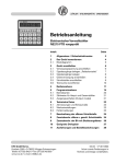
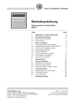
Komponenten Bedienfeld LED-Symbolanzeige
Bedientasten
Umschalttaste für
Funktionsanzeige
Einstelltaste der
Dekadenanwahl
Einstelltaste der
Dekadenwerte
X9750174-A020097MSC
LED-Symbolanzeige
Umschalttaste Programmier-/
Bedienerebene
Funktionstaste
Rückstelltaste
XP
P1
P2
SC
6
Aktueller Zählerstand
Vorwahlwert 1
Vorwahlwert 2
Setzwert
Gesamtsummenzähler
Betriebsstundenzähler
Seite 8
Funktionen, Bedienelemente und LED‘s
MICRO-EPSILON
Funktionsanzeige
LED-Symbolanzeige
Einstelltaste der Dekadenanwahl
Umschalttaste“Programmier-/Bedienerebene“
Einstelltaste der Dekadenwerte
2.2
Deutsch
Umschalttaste für Funktionsanzeige
Funktionstaste
Rückstelltaste
Blockdiagramm
Das Blockdiagramm zeigt die Bestandteile des Gerätes. Außerdem sind die Anschlüsse und Verbindungen
dargestellt.
Versorgungsspannung
Signaleingänge
A
B
A 90° B
Summenzähler
P1
Hauptzähler mit
2 Vorwahlen
Setzwert
Skalierungsfaktor
P2
Reset
Betriebsstundenzähler
Stop / Hold
optional
P1
P2
Sensorversorgung
Serielle Schnittstelle
T, RT, R+
Schnittstelle
RS232
Analogausgang
X9750174-A020097MSC
optional
Analogausgang
0(2) - 10 V
0(4) - 20 mA
Seite 9
Funktionen, Bedienelemente und LED‘s
2.3
MICRO-EPSILON
Technische Daten
Versorgungsspannung
Leistungsaufnahme
Sensorversorgung
Anzeige
Stellenzahl
Ziffernhöhe
Funktion
Skalierungsfaktor
Multiplikator / Nebenzähler
Zählweisen
Zählfrequenz
Betriebsarten
Datenspeicherung
Rückstellung
Ausgänge elektronisch
Ausgänge Relais
Haltezeit für Ausgänge
Analogausgang
Schnittstellen
Auslegung DIN EN 61010-1
Störaussendung
Störfestigkeit
Programmierbare Parameter
Zulassungen
X9750174-A020097MSC
Technische Daten - elektrisch
24 VDC ±10 %
7 VA, 5 W
12...26 VDC / max. 100 mA
LED, 7-Segment Anzeige
6-stellig
14 mm
Vorwahlzähler; Hauptzähler mit 2 Vorwahlen; Nebenzähler mit 1 Vorwahl;
0.0001 ... 9999.99
1...999
Addierend oder subtrahierend; A-B Differenz (Differenzzählung); A+B Summe (Parallelzählung);
3 Hz, 25 Hz, 10 kHz programmierbar
Stufenvorwahl, Hauptvorwahl, Parallelvergleich, Schleppvorwahl
>10 Jahre im EEPROM
Taste, elektrisch oder automatisch
Optokoppler
Wechsler potentialfrei (optional)
0,01 ... 99,99 s
0(2)...10 V, 0(4)...20 mA (optional)
RS232 (optional)
Schutzklasse II; Überspannungskategorie II; Verschmutzungsgrad 2
EN 50081-2
EN 50082-2
Zuordnung F1, F2 oder F3; Berechungsfunktionen; 2 Grenzwerte; Analogausgang;
UL/cUL, CE-konform
Seite 10
Funktionen, Bedienelemente und LED‘s
Deutsch
Technische Daten - mechanisch
Betrieb: -10...+50 °C; Lager -20...+70 °C
80 %, nicht kondensierend
Schraubklemme steckbar
1,5 mm²
IP 65 frontseitig mit Dichtring
Folie mit Kurzhubtasten
Einbaugehäuse
B x H x L 96 x 48 x 124 mm
96 x 45 mm (+0,6)
123,75 mm
Spannrahmen
ca. 250 g
Makrolon 6485 (PC)
Temperaturbereich
Relative Luftfeuchte
Anschluss
Aderquerschnitt
Schutzart DIN EN 60529
Bedienung / Tastatur
Gehäuseart
Abmessungen
Einbauausschnitt
Einbautiefe
Montageart
Masse
Werkstoff Gehäuse
2.4
MICRO-EPSILON
Technische Daten Analogausgang
Auflösung
Ausgangsbereiche
bei Stromausgang
1 Bit Wert
Max. Last (Bürde)
bei Spannungsausgang
1 Bit Wert
Min. Last (Bürde)
Genauigkeit
Nichtlinearität
Ausgangs Temperaturkoeff.
X9750174-A020097MSC
12 Bit (4096 Schritte)
0...20 mA / 4...20 mA (programmierbar)
4.884 μA
500 Ohm
0...10 V / 2...10 V (programmierbar)
2.442 mV
1000 Ohm
±0,1% auf Endwert
± 1LSB
typ. ± 50 ppm/ °C
Seite 11
Funktionen, Bedienelemente und LED‘s
MICRO-EPSILON
Fortsetzung Technische Daten Analogausgang
Auflösung
Ausgangsbereiche
bei Stromausgang
1 Bit Wert
Max. Last (Bürde)
bei Spannungsausgang
1 Bit Wert
Min. Last (Bürde)
Genauigkeit
Nichtlinearität
Ausgangs Temperaturkoeff.
3.
Lieferung
3.1
Lieferumfang
12 Bit (4096 Schritte)
0...20 mA / 4...20 mA (programmierbar)
4.884 μA
500 Ohm
0...10 V / 2...10 V (programmierbar)
2.442 mV
1000 Ohm
±0,1% auf Endwert
± 1LSB
typ. ± 50 ppm/ °C
Nach dem Auspacken sofort auf Vollständigkeit und Transportschäden überprüfen. Bei Schäden oder Unvollständigkeit wenden Sie sich bitte sofort an den Hersteller oder Lieferanten.
1 DD214NE
1 Betriebsanleitung
3.2
Lagerung
Lagertemperatur:
Luftfeuchtigkeit:
-20 bis +70 °C
Max. relative Feuchte 80 %, bei 25 °C nicht betauend
X9750174-A020097MSC
Seite 12
Montage
4.
MICRO-EPSILON
Montage
Achten Sie bei Montage und Betrieb auf sorgsame Behandlung.
4.1
Deutsch
Bei Veränderungen (einschließlich des Betriebsverhaltens), die die Sicherheit beeinträchtigen, ist das Gerät
sofort außer Betrieb zu setzen. Bei Installationsarbeiten an den Geräten ist die Stromversorgung unbedingt
abzuschalten. Installationsarbeiten dürfen nur von entsprechend ausgebildeten Fachkräften ausgeführt
werden. Nach korrekter Montage und Installation ist das Gerät betriebsbereit.
Maßzeichnung Anzeige
123,8
19,8
Dichtung
Einbauöffnung
92 +0,8 x 45 +0,6
48
96
109
1 - 10
Zusatzstecker bei Ausführung
Relaisausgänge, Analogausgang und Schnittstelle RS232
X9750174-A020097MSC
7
Seite 13
Montage
4.2
MICRO-EPSILON
Anzeigeeinheit anschließen
In diesem Kapitel wird zuerst die Anschlussbelegung sowie einige Anschlussbeispiele vorgestellt. In den
Kapiteln 4.2.1 bis 4.2.5 finden Sie konkrete Hinweise und technische Daten für die einzelnen Anschlüsse. Die
beiden Ein- und Ausgänge liegen auf zwei steckbaren Schraubklemmen. Die beiden 15-poligen Schraubklemmen sind pol-verlustfrei codiert.
29
RI
28
13
RU
14
27
12
(+)
11
26
Ausgang
30
(–)
15
Br.
Ausgang
22
7
- Klemme
max. 250 V
24
8
20
5
19
4
18
3
Klemme - Klemme
6
21
SensorZählung
versorgung
25
9
Rückstellung
23
10
Stop
2
17
1
16
+24 VDC
X9750174-A020097MSC
Pin
Funktion
1
2
3
4
5
6
7
8
9
10
11
12
13
unbelegt
Versorgungsspannung
Versorgungsspannung
Sensorversorgung 0 V
Sensorversorgung + 24
Signaleingang Spur A
Signaleingang Spur B
Reset
Signal Stopp
Vorwahl 1 (Kollektor)
Vorwahl 1 (Emitter)
Vorwahl 2 (Kollektor)
Vorwahl 2 (Emitter)
16–19
20–22
23–25
27
28
29
30
reserviert
reserviert
reserviert
reserviert
reserviert
reserviert
reserviert
für Option RS232
für Option Relaisausgang Grenzwert 1 (P1)
für Option Relaisausgang Grenzwert 2 (P2)
für Option Analogausgang
für Option Analogausgang (Brücke bei U)
für Option Analogausgang (I)
für Option Analogausgang (U)
Litzenanschluss aus
Gründen des Berührungsschutzes nach
VDE 0411 Teil 100 nur
mittels Aderendhülsen
mit Isolierstoffkappen.
MICRO-EPSILON
empfiehlt, alle SensorAnschlussleitungen
abzuschirmen und die
Abschirmung einseitig
zu erden.
Die Sensor-Anschlussleitungen sollen nicht
im gleichen Kabelstrang mit der Netzversorgung und den
Ausgangs-Kontaktleitungen geführt
werden.
Seite 14
Montage
MICRO-EPSILON
4.2.1 Versorgungsspannung anschließen
Störungsfreie Versorgungsspannung anschließen. Die Versorgungsspannung also nicht zur Parallelversorgung von Antrieben, Schützen, Magnetventilen usw. verwenden.
Gleichspannungsanschluss
Gleichspannung
Absicherung
24 V ±10 % max. 5 % RW
T 400 mA
X9750174-A020097MSC
Brandschutz: Gerät
netzseitig über die
am Anschlussschaltbild empfohlene externe Sicherung betreiben. Nach VDE
0411 darf im Störungsfall 8 A / 150 VA
(W) niemals überschritten werden.
Seite 15
Deutsch
Gleichspannung gemäß Anschlussplan anschließen. Pin 3 (+24 VDC) und Pin 2 (0 V).
Montage
MICRO-EPSILON
4.2.2 Optokoppler-Ausgänge
Die elektronischen Ausgänge (Anschlüsse 10, 11 und 12, 13) sind Optokoppler-Ausgänge. Kollektor- und
Emitteranschluss sind jeweils getrennt belegt. Die Zuordnung der Vorwahl erfolgt in der Programmierzeile 33
Max. Schaltspannung
+40 V
Max. Schaltstrom
15 mA
Max. Restspannung
1V
Anschlüsse 10, 11 und 12, 13 entsprechend belegen.
13
12
Vorwahl 2
11
10
Vorwahl 1
Die elektronischen
Ausgänge sind nicht
kurzschlussfest.
4.2.3 Relaiskontakte
Die Anschlüsse 20, 21 und 22 sowie 23, 24 und 25 sind potentialfreie Umschaltkontakte. Die Signalausgänge
können nach nebenstehendem Anschlussschema belegt werden. Die Zuordnung der Relais als Schließer
oder Öffner erfolgt in der Programmierzeile 33.
Max. Schaltleistung
150 VA/30 W
Max. Schaltspannung
250 V
Max. Schaltstrom
1A
Anschlüsse 20, 21 und 22 sowie 23, 24 und 25 entsprechend belegen.
25 24 23
Vorwahl 2
22 21 20
Vorwahl 1
Der Anwender muss dafür sorgen, dass bei einem Störfall eine Schaltlast von 8 A / 150 VA (W) nicht überschritten wird. Funkenlöschung intern mit 2 Zink-Oxyd-Varistoren (275 V). Die Ausgangsrelais des Gerätes (1
Relais oder mehrere) dürfen in der Summe max. 5 x pro Minute schalten. Zulässige Knackstörungen nach
Funkentstörnorm EN 55011, EN 50081-2 für den Industriebereich. Bei höherer Schalthäufigkeit muss der
Betreiber, eigenverantwortlich unter Berücksichtigung der zu schaltenden Last, für die Funkentstörung vor Ort
sorgen.
X9750174-A020097MSC
Seite 16
Montage
MICRO-EPSILON
Eingangswiderstand
Schaltschwelle
Max. Eingangspegel
Max. Frequenz
Min. Bedämpfung
Deutsch
4.2.4 Signaleingänge belegen
Die Anschlüsse 6 bis 9 sind AC-Signaleingänge. Die Anschlüsse 6 (Spur A) und 7 (Spur B) sind Zähleingänge
für den Zähler. Die Signalart und Signallogik werden in den Zeilen 25 und 28 programmiert. Der Anschluss 8
(Reset) dient als Rückstelleingang. Durch Anlegen eines externen Signals (Signalbreite > 30 ms) wird der
Zähler zurückgesetzt. Der Anschluss 9 (Stopp) dient als Stopp- / Hold- / Printeingang (Zeile 31).
3 kOhm
x2,5 V / x5 V oder x11 V
± 40 V
10 kHz
3 Hz
Eingangslogik PNP
Eingangslogik NPN
Anschlüsse 6 bis 9 entsprechend belegen.
4.2.5 Sensorversorgung anschließen
Sensorversorgung an die Anschlüsse 4 und 5 anschließen. Sensorversorgung jedoch nicht zur Versorgung
ungelöschter Induktivitäten oder kapazitiver Lasten benutzen.
Pin
Spannung
4
0V
5
+24 VDC
+10 % / -50 %
X9750174-A020097MSC
Max. zulässiger Strom
/
100 mA
Die Sensorversorgung ist nicht kurzschlussfest.
Seite 17
Montage
18
17 16
TxD
19
GND
RxD
4.2.6 RS232-Schnittstelle anschließen (Option)
Folgende Funktionen kann die serielle Schnittstelle ausführen:
– Daten abrufen
– Parameter programmieren
Schnittstellenparameter sind:
– die Übertragungsgeschwindigkeit (Baudrate),
– das Paritybit,
– Anzahl der Stoppbits,
– die Adresse, mit der die Anzeigeeinheit von einem Master angesprochen wird.
MICRO-EPSILON
RS232
Diese Schnittstellenparameter können in der Programmierebene (Zeilen 51, 52, 53 und 54) eingestellt werden.
Eigenschaften der Schnittstelle
Vollduplex-Übertragung mit den Eigenschaften:
– asymmetrisch
– 3 Leitungen
– Punkt-zu-Punkt-Verbindung – 1 Sender und 1 Empfänger
– Datenübertragungslänge: max. 30 m
Anschlüsse 16, 18 und 19 entsprechend belegen.
X9750174-A020097MSC
Seite 18
Montage
MICRO-EPSILON
Tasten
und
im spannungslosen Zustand gleichzeitig drücken.
Gerät einschalten (obige Tasten solange gedrückt halten). Alle Anzeigensegmente
werden automatisch nacheinander angezeigt und damit auf ihre Funktionstüchtigkeit
geprüft.
Mit der Taste
nacheinander die Tastatur, die Eingänge, Ausgänge und Schnittstelle
prüfen.
Test-Erweiterung
Beim Test der Ausgänge darf keine
Maschinenfunktion
angeschlossen sein.
Test der Tastatur
Test der Eingänge
Die Eingänge können gleichzeitig oder einzeln angesteuert werden. Im Ruhezustand ist die
Anzeige aktiv.
Test der Ausgänge
Tasten
und
drücken.
Ausgänge sind aktiviert. Die Ausgänge werden mit der Taste
zurückgestellt.
Test des Analogausganges (nur bei der Option mit Analogausgang)
Anzeigen-Beispiele
Anzeige: Programmnummer und Versionsnummer.
Anzeige: Programmdatum.
Test verschiedener Eingangspegel (Schaltschwellen), Signalformen und des Phasendiskriminators (Test von Nummer 1 bis 8)
X9750174-A020097MSC
Seite 19
Deutsch
4.2.7 Testroutine durchführen
Hier finden Sie eine Beschreibung der Testroutine.
Montage
Test-Ende
MICRO-EPSILON
Die Testroutine kann nur durch Ausschalten des Geräts beendet werden. Nach erneutem
Einschalten der Netzversorgung befindet sich der Zähler in der Bedienerebene.
Test
Taste
Programmversion
drücken, Gerät einschalten (Taste gedrückt halten).
Anzeige: Programmnummer und Versionsnummer.
Anzeige: Programmdatum.
5.
Bedienung
In diesem Kapitel lesen Sie die Bedienung und Anwendung des Zählers. Das Gerät befindet sich nach dem
Einschalten der Versorgungsspannung automatisch in der Bedienerebene.
In der Bedienerebene kann/können
– der aktuelle Zählerstand abgelesen und gelöscht werden;
– die eingestellten Vorwahlwerte abgelesen und ggf. verändert werden;
– die Gesamtsummenzahl abgelesen und gelöscht werden;
– der eingestellte Setzwert abgelesen und ggf. verändert werden;
– der Betriebsstundenzähler abgelesen und gelöscht werden.
In der Programmierebene können alle Parameter gesperrt werden.
X9750174-A020097MSC
Seite 20
Bedienung
Aktueller Hauptzähler
Zählerstand ablesen.
Taste drücken.
Ablesen
Vorwahlwert P1
Taste
drücken.
Vorwahlwert P1 ablesen.
Ändern
Vorwahl P1 über
und
Deutsch
Ablesen
Rückstellen
MICRO-EPSILON
eingeben, Vorzeichen nur möglich nach Freigabe in Zeile 38.
Taste
drücken.
Änderung ist beendet.
Ablesen
Vorwahlwert P2
Taste
drücken.
Vorwahlwert P2 ablesen.
Ändern
Vorwahl P2 über
und
eingeben, Vorzeichen nur möglich nach Freigabe in Zeile 38.
Taste
drücken.
Änderung ist beendet.
X9750174-A020097MSC
Seite 21
Bedienung
MICRO-EPSILON
Ablesen
Setzwert SC
Taste
drücken.
Laufenden Wert des Grenzwertes SC ablesen.
Ändern
Setzwert SC über
und
eingeben, Vorzeichen nur möglich nach Freigabe in Zeile 38.
Taste
drücken.
Änderung ist beendet.
Ablesen
Rückstellen
Ablesen
Rückstellen
Gesamtsumme
Taste
drücken.
Gesamtsumme ablesen.
Taste
drücken.
Betriebsstunden
Taste
drücken.
Betriebsstunden ablesen.
Taste
drücken.
.
X9750174-A020097MSC
Nach 15 Sekunden
ohne Tastenbestätigung wird der vorherige Grenzwert automatisch wieder angezeigt.
Seite 22
Programmierebene
6.
MICRO-EPSILON
Programmierebene
In diesem Kapitel finden Sie die Beschreibung, wie Sie das Gerät programmieren. In der Programmierebene
werden Betriebsparameter eingestellt. Die Programmierebene ist in 3 Programmierfelder gegliedert.
Deutsch
1. Programmierfeld
Im ersten Programmierfeld können alle Betriebsparameter angewählt und geändert werden. Hier werden
auch die Betriebsparameter angezeigt, die in der Bedienerebene gesperrt sind. Das erste Programmierfeld
besteht aus 6 Zeilen.
2. Programmierfeld
Im zweiten Programmierfeld können die einzelnen Betriebsparameter für den Zugriff in der Bedienerebene
gesperrt und freigegeben werden (Status). Im ersten Programmierfeld ist ein Zugriff auf diese gesperrten
Betriebsparameter möglich.
3. Programmierfeld
Im dritten Programmierfeld können alle maschinenbedingten Funktionen und Werte sowie der Analogausgang programmiert werden.
Tastenbedienung
Für die einzelnen Programmierfelder ist die Tastenbedienung einheitlich. Die Tastenbedienung kann in
Bediener- und Programmierebene unterschiedlich sein. Daher sind alle Funktionen vollständig beschrieben.
Taste
Auf den nächsten Betriebsparameter in der Bediener- und Programmierebene umschalten, für Schnelldurchlauf die Taste gedrückt halten.
Bediener- und
Programmierebene
Taste
Programmierebene/Bedienerebene umschalten.
Bediener- und
Programmierebene
X9750174-A020097MSC
Seite 23
Programmierebene
MICRO-EPSILON
Taste
Erste oder nächste gewünschte Dekade anwählen. Die jeweils angewählte Dekadenstelle blinkt.
Taste
Anzeige wird gelöscht.
Bedienerebene
Anzeige wird gelöscht. Rückstellung auf die Zahl Null. Rückstellung der möglichen programmierten Betriebsparameter.
Taste
Umschaltung von beliebiger Anzeige zu einem Parameter entsprechend der Auswahl in Zeile 39.
In Verbindung mit der Taste
Bediener- und
Programmierebene
umschalten in die Programmierebene.
Taste
Beim Drücken der Taste schaltet die betreffende Dekadenstelle um einen Wert weiter.
Beim Drücken der Taste schaltet die betreffende Dekadenstelle um einen Wert weiter bis zum maximalen
Einstellwert.
Programmierebene
Bedienerebene
Programmierebene
Bedienerebene
Programmierebene
Das Einrichten der Programmierung und die 3 Programmierfelder werden nun in der Reihenfolge ihrer
Anwendung beschrieben.
X9750174-A020097MSC
Seite 24
Programmierebene
6.1
MICRO-EPSILON
Programmierung einschalten
wird angezeigt. Der Code besteht für die Programmierfelder 1 - 3.
Code eingeben
Taste
und
.
Bei Auslieferung ist
kein Code eingeben.
drücken.
Falscher Code eingegeben:
erscheint in der Anzeige, solange die Taste
gedrückt wird.
Nach 15s wird automatisch in die Bedienerebene zurückgeschaltet.
Taste
drücken.
Taste
drücken.
Korrekten Code eingeben.
Korrekter Code unbekannt
Ist der korrekte Code nicht bekannt:
Zähler bitte an das Werk zurückschicken
Korrekter Code
Bei korrektem Code Taste
drücken.
Nun werden die Bedienfelder nacheinander aufgerufen.
X9750174-A020097MSC
Seite 25
Deutsch
Taste
drücken.
Von der Bedienerebene wird in die Programmierebene umgeschaltet.
Taste
drücken.
Programmierebene
6.2
MICRO-EPSILON
Programmierfeld 1
Informationen über die Anzeigen und über die Änderung der einzelnen Werte finden Sie auch im Kapitel 5.
Wiederholt Taste
drücken.
Die Betriebsparameter werden nacheinander angewählt. Die jeweilige LED blinkt.
Betriebsparameter ändern
Geänderten Wert über die Tasten
und
eingeben.
XP - Aktueller Zählerstand
1. Zeile
P1 - Vorwahlwert 1
2. Zeile
P2 - Vorwahlwert 2
3. Zeile
SC - Setzwert
4. Zeile
6 - Gesamtsummenzähler
5. Zeile
- Betriebsstundenzähler
6. Zeile
Nach Ablauf des ersten Programmierfeldes erscheint eine Strichlinie in der Anzeige.
6.3
Programmierfeld 2
Im zweiten Programmierfeld erscheint in der Anzeige das Zeichen STAT für die Status-Anwahl.
erscheint in der Anzeige. Die entsprechende LED des Betriebsparameters blinkt.
Bedeutung der Status-Zahlen
0
Betriebsparameter kann in der Bedienerebene angewählt, abgelesen und geändert werden.
1
Betriebsparameter kann in der Bedienerebene angewählt und abgelesen werden.
2
Betriebsparameter wird für die Bedienerebene völlig gesperrt. Bei der Anwahl dieses Betriebsparameters wird dieser in der Bedienerebene nicht angezeigt, sondern übersprungen. Die entsprechende
Funktion bleibt erhalten.
X9750174-A020097MSC
Seite 26
Programmierebene
MICRO-EPSILON
XP - Aktueller Zählerstand
11. Zeile
P1 - Vorwahlwert 1
12. Zeile
P2 - Vorwahlwert 2
13. Zeile
SC - Setzwert
14. Zeile
6 - Gesamtsummenzähler
15. Zeile
- Betriebsstundenzähler
16. Zeile
Nach Ablauf dieser Programmierzeilen erscheint eine Strichlinie auf der Anzeige. Die Strichlinie stellt das Ende des zweiten Programmierfeldes dar.
X9750174-A020097MSC
Deutsch
Status ändern
Entsprechende Status-Zahl eingeben.
Wiederholt Taste
drücken.
Der Status jedes einzelnen Betriebsparameters wird in Folge angewählt.
Bei Werksauslieferung
ist der Status für alle
Betriebsparameter auf
Null eingestellt.
Seite 27
Programmierebene
6.4
MICRO-EPSILON
Programmierfeld 3
Das Programmierfeld 3 beginnt mit der Programmierzeile 22. In diesen Programmierfeldern werden die
Programmierzeilen nacheinander angezeigt. Die Programmierzeilen werden nacheinander angewählt. Die
Eingabe wird abgespeichert, wenn die nächste Programmierzeile abgerufen wird.
Betriebsarten
0
1
* Stufenvorwahl
Hauptvorwahlen
2
3
Die Werkseinstellung
ist jeweils durch einen * gekennzeichnet.
22. Zeile
Parallelvergleich
P1-Schleppvorwahl
Skalierungsfaktor Hauptzähler
Skalierungsbereich 0.0001 bis 9999.99
23. Zeile
* 1.0000
0.0001 – 9999.99
Dezimalpunkt (gültig für XP, P1, P2, SC, S)
0
1
* Kein Dezimalpunkt
00000.0
2
3
0000.00
000.000
4
00.0000
0
1
2
3
4
5
* Spur A und UP/DOWN-Signal auf Spur B
Differenzzählung Spur A addierend und Spur B subtrahierend (A-B)
Summenzählung Spur A addierend und Spur B addierend (A+B)
Spur A 90° Spur B Einfachauswertung
Spur A 90° Spur B Zweifachauswertung
Spur A 90° Spur B Vierfachauswertung
24. Zeile
Zählweise
25. Zeile
Bei Einstellung Spur A 90° Spur B müssen die Eingangsfrequenzen für Spur A und Spur B auf 10 kHz (Zeilen
26 und 27) eingestellt sein.
X9750174-A020097MSC
Seite 28
Programmierebene
MICRO-EPSILON
Frequenz Hauptzähler Spur A
0
1
10 kHz
25 Hz
2
3 Hz
26. Zeile
0
1
* 10 kHz
25 Hz
2
3 Hz
27. Zeile
0
1
2
* PNP Schaltschwelle 11 V
NPN Schaltschwelle 11 V
PNP Schaltschwelle 5 V
3
4
5
NPN Schaltschwelle 5 V
PNP Schaltschwelle 2,5 V
NPN Schaltschwelle 2,5 V
28. Zeile
Deutsch
Frequenz Hauptzähler Spur B
Eingangslogik
Rückstellung Hauptzähler
0
1
2
* Automatische Rückstellung und extern statisch
Automatische Rückstellung und extern differenziert
Extern statisch
3 Extern differenziert
29. Zeile
Funktion Signaleingang 9 (Stopp/Hold)
0
1
2
*Stopp
Hold
Keylock
3
4
Betriebsstundenzähler Ein/Aus
Print (Nur mit Schnittstellenoption möglich)
31. Zeile
2
3
P1 Schließer, P2 Öffner
beide Ausgänge als Öffner
33. Zeile
Ausgangslogik für Digitalausgänge
0
1
* Beide Ausgänge als Schließer
P1 Öffner, P2 Schließer
X9750174-A020097MSC
Seite 29
Programmierebene
MICRO-EPSILON
Ausgangszeit P1
* Angaben in Sekunden (Tol. -0,01s, Bereich 00,02-99,99 s)
00,25 0,25 s
99.99 maximale Wischzeit
LAtch LAtch = Dauersignal (Löschen durch -Taste oder extern)
35. Zeile
Ausgangszeit P2
* Angaben in Sekunden (Tol. -0,01s, Bereich 00,02-99,99 s)
00,25 0,25 s
99,99 maximale Wischzeit
LAtch LAtch = Dauersignal (Löschen durch -Taste oder extern)
36. Zeile
Übernahme der Vorwahlen P1, P2, SC
0
* Sofort wirksam
1
Bei Rückstellung
37. Zeile
P1, P2 und SC aktiv
0
1
38. Zeile
* nur im pos. Zählbereich
im pos. und neg. Zählbereich
Zuweisung Funktionstaste
0
1
2
* Ohne Funktion
XP
P1
3
4
5
P26
SC
S
39. Zeile
Code-Einstellung
0
* Kein Code
1 - 9999
X9750174-A020097MSC
40. Zeile
Seite 30
Programmierebene
MICRO-EPSILON
Funktion des Nebenzählers
0
1
* Als Gesamtsummenzähler Teiler 1
Als Gesamtsummenzähler Teiler 10
2
3
Als Gesamtsummenzähler Teiler 100
Zählung beim Erreichen von P2
41. Zeile
0
0
* Default
Min.
999 Max.
42. Zeile
0
1
* 4800 Baud
2400 Baud
2
3
1200 Baud
600 Baud
51. Zeile *
0
1
* Even Parity
Odd Parity
2
No Parity
52. Zeile *
0
* 1 Stoppbit
1
2 Stoppbits
53. Zeile *
0
0
* Default
Min.
99 Max.
54. Zeile *
1 Nebenzähler
61. Zeile *
Deutsch
Multiplikator Nebenzähler (nur wenn Zeile 41=3)
Baudrate
Parity
Stoppbits
Adresse
Zuordnung Analogausgang
0 * Hauptzähler
X9750174-A020097MSC
Seite 31
Programmierebene
MICRO-EPSILON
Offset Analogausgang
0
* kein Offset
1
Offset 2 V/4mA
62. Zeile *
2
3
P1
P2
63. Zeile *
Zuordnung unterer Analoggrenzwert
0
1
* Variabler Wert aus Zeile 64
SC
Unterer Analoggrenzwert
0
-999999
999999
64. Zeile *
* Default
Min.
Max.
Zuordnung oberer Analoggrenzwert
0 * Variabler Wert aus Zeile 66
1 SC
2
3
P1
P2
65. Zeile *
Oberer Analoggrenzwert
4095
-999999
999999
* Default
Min.
Max.
Nach Ablauf dieser Programmierzeilen erscheint eine Strichlinie auf der Anzeige. Die Strich-
66. Zeile *
* Funktionen von
DD214NE(01)
linie stellt das Ende des Programmierfeldes dar.
X9750174-A020097MSC
Seite 32
Programmierebene
gedrückt halten und wiederholt Taste
drücken.
Zurückschalten der
Programmierzeilen
Taste
drücken.
Zähler befindert sich in der Bedienerebene.
Programmierung
ausschalten
Taste
und
gleichzeitig drücken, dann Gerät einschalten.
Alle bereits programmieren Werte werden auf die Werkseinstellung zurückprogrammiert. In der Anzeige erscheint kurz „Clr Pro.“
Zähler auf Werkseinstellung zurückprogrammieren
6.5
Betriebsarten (Zeile 22)
Nachfolgend werden die Betriebsarten beschrieben.
Stufenvorwahl
Das Gerät zählt bei Erreichen eines Vorwahlwertes zum nächsten Vorwahlwert weiter. Die Vor-wahlwerte
werden immer in der Reihenfolge 1. Vorwahlwert und 2. Vorwahlwert abgearbeitet. Die Vorwahlwerte können
beliebig gewählt werden. Eine automatische Rückstellung auf den Setzwert ist bei dem zweiten Vorwahlwert
möglich. Eine externe oder manuelle Rückstellung ist jederzeit möglich.
Hauptvorwahl
Der Zähler wird bei Erreichen der einzelnen Vorwahlwerte auf den Setzwert zurückgesetzt. Die Vorwahlwerte
werden immer in der Reihenfolge 1. Vorwahlwert und 2. Vorwahlwert abgearbeitet. Eine auto-matische
Rückstellung auf den Setzwert ist bei P2 möglich. Eine externe oder manuelle Rückstellung ist jeder-zeit
möglich.
Parallelvergleich
Bei Erreichen der Vorwahlwerte schalten die Ausgänge als Dauersignale bei Überschreitung des jeweiligen
Vorwahlwertes in beide Zählrichtungen. Die Vorwahlwerte können beliebig gewählt werden und arbeiten
unabhängig voneinander. Wischsignale sind bei Parallelvergleich nicht möglich.
X9750174-A020097MSC
Seite 33
Deutsch
Taste
MICRO-EPSILON
Programmierebene
MICRO-EPSILON
P1- Schleppvorwahl
Der Vorwahlwert P1 dient als Vorsignal und arbeitet als Schleppvorwahl. Das Vorsignal schaltet immer um den
eingegebenen Wert vor dem Endsignal. Der 2. Vorwahlwert kann beliebig gewählt werden.
6.6
Zeile
Programmierzeilen
Werkseinstellung
Kundenprogramm
Kurzbeschreibung
01
XP - Zählerstand Hauptzähler
02
P1 - Vorwahl 1
03
P2 - Vorwahl 2
04
SC - Setzwert
05
6 - Summenzähler
06
- Betriebsstundenzähler
10
Trennzeile
11
XP - Zählerstand Hauptzähler
12
P1 - Vorwahl 1
13
P2 - Vorwahl 2
14
SC - Setzwert
15
6 - Summenzähler
16
20
X9750174-A020097MSC
- Betriebsstundenzähler
Trennzeile
Seite 34
Programmierebene
Werkseinstellung
Kundenprogramm
Kurzbeschreibung
22
Betriebsarten
23
Skalierungsfaktor
24
Dezimalpunkt
25
Zählweise
26
Frequenz Hauptzähler Spur A
27
Frequenz Hauptzähler Spur B
28
Eingangslogik
29
Rückstellung Hauptzähler
31
Funktion Signaleingang 9 (Stopp/Hold/Print)
33
Ausgangslogik für Digitalausgang
35
Wischsignalzeit P1
36
Wischsignalzeit P2
37
Übernahme der Vorwahlen P1, P2, SC
38
Vorwahlerkennung
39
Adresse für Funktionstaste
X9750174-A020097MSC
Deutsch
Zeile
MICRO-EPSILON
Seite 35
Programmierebene
Werkseinstellung
Kundenprogramm
Kurzbeschreibung
40
Code
41
Funktion des Nebenzählers
42
Multiplikator des Nebenzählers
51
Baudrate
52
Parity
53
Stopp Bit
54
Adresse
61
Zuordnung Analogausgang
62
Offset für Analogausgang
63
Zuordnung unterer Analoggrenzwert
64
Unterer Analoggrenzwert
65
Zuordnung oberer Analoggrenzwert
66
Oberer Analoggrenzwert
67
Trennzeile
X9750174-A020097MSC
Nur zugänglich für DD214NE(01).
Zeile
MICRO-EPSILON
Seite 36
Programmierebene
6.7
MICRO-EPSILON
Zählweisen für Haupt- und Gesamtsummenzähler (Input Modes)
Dieser Zähler kann vor- und rückwärts zählen. Die Zählrichtung ist unabhängig von der addierenden oder
subtrahierenden Betriebsart. Ausnahme ist die Summenzählung (A+B).
Vor-/ Rückwärtszählung mit einer Zählspur A
und externes Up/Down-Signal auf Spur B
Deutsch
Spur A
Up/Down
Zählung
Differenzzählung Spur A addierend
und Spur B subtrahierend (A-B)
Signaldauer und Zeitpunkt beliebig.
Summenzählung Spur A addierend
und Spur B addierend (A+B)
Die Betriebsart und damit die Zählrichtung wird in
der Programmierebene gewählt.
Vor-/Rückwärtszählung mit zwei um 90 °
phasenversetzten Zählsignalen
Die Zählrichtung wird automatisch erkannt aus
dem 90 ° vor- und nacheilenden Phasenversatz.
Der interne Phasendiskriminator wertet aus.
Zwei- oder Vierfachauswertung ist möglich.
X9750174-A020097MSC
Seite 37
Programmierebene
6.8
MICRO-EPSILON
Ausgangsverhalten (Output Modes)
Das Verhalten der Signalausgänge wird bestimmt durch
– Programmierung des Vorwahlwertes, des Setzwertes, der Ausgangszeit, der Ausgangslogik, der Aus
gangsfunktion,
– externe Rückstellung,
– externe Zählsteuerung.
Die nachstehenden Diagramme zeigen das Ausgangsverhalten der Signalausgänge.
Addierende Betriebsart
Subtrahierende Betriebsart
Stufenvorwahl mit Dauersignal, ohne automatische Rückstellung
RESET
RESET
VW (P2)
SC
VW (P1)
VW (P1)
VW (P2)
O
O
OUT 1
OUT 1
OUT 2
OUT 2
Stufenvorwahl mit Wischsignal, ohne automatische Rückstellung
RESET
RESET
VW (P2)
SC
VW (P1)
VW (P1)
VW (P2)
O
O
OUT 1
OUT 1
OUT 2
OUT 2
Tw
X9750174-A020097MSC
Seite 38
Programmierebene
MICRO-EPSILON
RESET
RESET
VW (P2)
VW (P1)
SC
VW (P1)
O
VW (P2)
SC
O
OUT 1
OUT 1
OUT 2
OUT 2
Deutsch
Addierende Betriebsart
Subtrahierende Betriebsart
Stufenvorwahl mit Wischsignal, aber Vorkontakt als Dauersignal, mit automatischer Rückstellung
Tw
Tw
Hauptvorwahl mit Wischsignal, mit automatischer Rückstellung
RESET
RESET
VW (P2)
VW (P1)
SC
VW (P1)
O
VW (P2)
SC
O
OUT 1
OUT 1
Tw
Tw
OUT 2
OUT 2
Tw
Tw
Hauptvorwahl mit Wischsignal, aber Ausgangssignal P1 als Dauersignal, mit automatischer Rückstellung
RESET
RESET
VW (P2)
SC
VW (P1)
VW (P1)
VW (P2)
O (B1)
O
OUT 1
OUT 1
OUT 2
O
Tw
X9750174-A020097MSC
Tw
Seite 39
Programmierebene
MICRO-EPSILON
Addierende Betriebsart
Subtrahierende Betriebsart
Hauptvorwahl mit Wischsignal, ohne automatische Rückstellung
Setzwert bei Null
RESET
RESET
VW (P2)
SC
VW (P1)
VW (P1)
VW (P2)
O
O
OUT 1
OUT 1
Tw
Tw
OUT 2
OUT 2
Tw
Tw
Parallelvergleich
Bei subtrahierender Betriebsart ist kein sinnvoller
Betrieb möglich.
RESET
VW (P2)
VW (P1)
O (B1)
OUT 1
OUT 2
Schleppvorwahl mit Wischsignal, ohne automatische Rückstellung
RESET
VW (P2)
VW (P1)
O (B1)
SC
OUT 1
Tw
OUT 2
Tw
X9750174-A020097MSC
Die Eingabe des Vorwahlwertes
P1 entspricht dem Abstand des
Vorsignals vor dem Endsignal. Das
heißt, bei Veränderung des Endsignals, also des Vorwahlwertes
P2, wird das Vorsignal automatisch nachgezogen.
Addierende Betriebsart
ist dann gegeben, wenn
der Setzwert SC kleiner
als die beiden Vorwahlen
P1 und P2 gewählt
wurde.
Subtrahierende Betriebsart ist dann gegeben,
wenn der Setzwert SC
größer als die beiden
Vorwahlen P1 und P2 gewählt wurde.
Seite 40
RS232 (Option)
7.
MICRO-EPSILON
RS232 (Option)
7.1
Deutsch
Die serielle Schnittstelle kann die gleichen Funktionen erfüllen, wie das Display und die Tastatur am
DD214NE. Über die Schnittstelle können Sie Daten abrufen und Parameter umprogrammieren. Im Allgemeinen wird das DD214NE beim Betrieb mit der seriellen Schnittstelle von einer SPS oder einem PC bedient. Es
kann jedoch auch ein anderes Gerät mit ähnlichen Eigenschaften verwendet werden.
Übertragungsprotokoll
Die Übertragung erfolgt zeichenweise im ASCII-Code. Jedes Zeichen besteht aus 8 Bit. Das 8. Bit ist das Parity
Bit, bei "no Parity" wird als 8. Bit immer eine Null gesendet.
Das DD214NE sendet auf jede Anforderung vom PC über die serielle Schnittstelle eine Antwort, sofern die
Datenübertragung korrekt erfolgt ist. Eine Übertragung von Zeichen wird mit einem Startzeichen <STX> (=
2Hex) eingeleitet und mit einem Endezeichen <ETX> (= 3Hex) abgeschlossen. Zusätzlich wird vom
DD214NE nach dem <ETX> noch ein <CR> (Wagenrücklauf = 0DHex) gesendet. Dies ermöglicht das
Einlesen (bei Hochsprachen) eines kompletten Datenblocks mit einem Befehl.
Nach dem <STX> folgt eine dem DD214NE zugeordnete Geräte-Adresse. Somit kann das DD214NE in einem
seriellen Netzwerk gezielt angesprochen werden. Nach der Adresse folgen die Zeilennummer (Position), die
Sie auslesen oder programmieren können, sowie bei einem Programmierbefehl das Zeichen "P" für Programmieren und die entsprechenden Daten bzw. Parameter.
Das Protokoll wird, wie nachfolgend dargestellt, in 3 Gruppen unterteilt:
a) Lesen von Speicherplätzen (READ-Anweisung):
<STX> Adresse Zeile <ETX> [<CR>]
b) Programmieren von Speicherplätzen (WRITE-Anweisung):
<STX> Adresse Zeile P Daten <ETX> [<CR>]
X9750174-A020097MSC
Seite 41
RS232 (Option)
MICRO-EPSILON
c) Sonderbefehle:
<STX> Adresse Parameter <ETX> [<CR>]
<STX>
Adresse
Zeile
P
Daten
Parameter
<ETX>
<CR>
Start of Text (02Hex)
00 ... 99 (Geräteadresse)
01 ... XX (siehe Bedienungsplan)
Programmierbefehl
Programmierdaten
Sonderbefehle
End of Text (03Hex)
0DHex (Steuerzeichen "carriage return")
"CR" muss nicht angegeben werden (optional), wird aber vom DD214NE immer zurückgesendet.
Allgemeines
Allgemein
ASCII
Hex
Beispiel:
<STX> Adresse Zeile <ETX>
<STX>3502<ETX>
02H,33H,35H,30H,32H,03H
(Adresse = 35; Zeile = 02)
WICHTIG!
Die Leerstellen zwischen den einzelnen Zeichen in den Befehlen dienen nur zur besseren Darstellung. Die
Eingabe am PC muss ohne Leerstellen erfolgen. Steuerzeichen (kleiner 20Hex) sind in der Beschreibung in
spitze Klammern eingefasst.
Wird ein falsches Protokoll vom PC gesendet, gibt das DD214NE eine Fehlermeldung zurück. Dies setzt
voraus, dass das DD214NE noch ansprechbar bleibt. Lesen Sie dazu auch das Kap. 7.5 “Fehlermeldungen
beim Datentransfer“.
X9750174-A020097MSC
Seite 42
RS232 (Option)
7.2
MICRO-EPSILON
Lesen von Speicherplätzen
Deutsch
Sämtliche Speicherplätze, die im Programmierschema mit einer Zeilennummer versehen sind, können ausgelesen werden (außer den Trennzeilen, die durch Striche gekennzeichnet sind). Das Protokoll: <STX> Adresse
Zeile <ETX> [<CR>] kann auf jede Zeile angewendet werden. Die Rückantwort vom DD214NE kann jedoch
von Zeile zu Zeile unterschiedlich in der Protokolllänge ausfallen. Dies hängt von der Datenlänge des jeweiligen Speicherplatzes ab. Das DD214NE kann, wenn es sich im RUN-Modus wie auch im PGM-Modus befindet,
gleichermaßen ausgelesen werden. Der Unterschied liegt lediglich darin, dass bei der Rückmeldung für den
Mode-Parameter ein "R" oder "P" zurückgeliefert wird, wie nachfolgend beschrieben.
Antwort auf einen Read-Befehl (allgemein):
<STX> Adresse Zeile Mode [VZ] Daten <ETX> <CR>
Mode
P = DD214NE befindet sich im Programmiermodus
R = DD214NE befindet sich im RUN-Modus
VZ
Vorzeichen. Wird nur bei einem Minuszeichen übertragen
Daten max. Stellenzahl, mit führenden Nullen ohne Dezimalpunkt
(Ausnahme: Zeile 23 - dort mit Dezimalpunkt)
Beispiele zum Lesen von Speicherplätzen
Für die nachfolgenden Beispiele gilt folgende Festlegung:
Geräteadresse = 35; Modus des DD214NE = R (RUN-Modus)
Auslesen des Hauptzählers XP (Zeile = 01), Anzeigewert = 1500)
Anfrage: <STX>3501<ETX>
Antwort: <STX>3501R001500<ETX><CR>
Auslesen der Zählweise (Zeile = 25), Einstellung = 3)
Anfrage: <STX>3525<ETX>
Antwort: <STX>3525R3<ETX><CR> (3 entspricht Spur A90 °, B Einfachauswertung)
X9750174-A020097MSC
Seite 43
RS232 (Option)
MICRO-EPSILON
Auslesen des Skalierungsfaktors SF (Zeile = 23), Einstellung = 01,0000)
Anfrage: <STX>3523<ETX>
Antwort: <STX>3523R01.0000<ETX><CR>
Auslesen der Geräte-Adresse (Zeile = 54, Wert = 35)
Anfrage: <STX>3554<ETX>
Antwort: <STX>3554R35<ETX><CR>
7.3
Programmieren von Speicherplätzen
Sämtliche Speicherplätze, die im Programmierschema mit einer Zeilennummer versehen sind, mit Ausnahme
der Trennzeilen (durch Striche gekennzeichnet) sowie den Zeilen 1, 5 und 6, können programmiert werden.
Das Protokoll: <STX> Adresse Zeile P [VZ] Daten <ETX> [<CR>] kann auf jede Zeile angewendet werden.
Die Rückantwort vom DD214NE, die nach jedem Programmieren zurückgesendet wird, ist dieselbe, wie beim
Auslesen der Zeile.
Das Programmieren aller Speicherplätze kann im RUN- sowie im Programmier-Modus erfolgen.
Programmieren im RUN-Modus
Die Daten in den Zeilen 22, 23, 25 - 29, 31, 41/3, 51 - 54, und 62 - 66 werden erst nach einem Wechsel vom
PGM-Modus in den RUN-Modus intern übernommen. Umschalten in den PGM-Modus siehe Kapitel 7.4.2. Die
übrigen Zeilen sind sofort nach der Programmierung aktiv.
Alle im RUN-Modus programmierten Daten werden erst nach einem Wechsel vom PGM-Modus in den RUNModus in den nichtflüchtigen Speicher übernommen. Erfolgt kein PGM/RUN-Wechsel, werden nach einem
Netzausfall die alten Daten wieder gültig.
Write-Befehl (allgemein):
<STX> Adresse Zeile P [VZ] Daten <ETX> [<CR>]
X9750174-A020097MSC
WICHTIG!
Die max. Anzahl der
Speicherzyklen des
nichtflüchtigen Speichers beträgt
1.000.000.
Seite 44
RS232 (Option)
MICRO-EPSILON
Beispiele
Folgende Festlegung gilt für die nachfolgenden Beispiele:
Geräteadresse = 35; Modus des DD214NE = R (RUN-Modus)
Deutsch
Programmieren des Setzwertes SC (Zeile = 04, Einstellung = 360)
Befehl: <STX>3504P000360<ETX>
Antwort: <STX>3504R000360<ETX><CR>
Programmieren des Skalierungsfaktors SF (Zeile = 23, Einstellung = 01,0000)
Befehl: <STX>3523P01.0000<ETX>
Antwort: <STX>3523R01.0000<ETX><CR>
Programmieren der Zählweise (Zeile = 25, Zählweise = 1)
Befehl: <STX>3525P1<ETX>
Antwort: <STX>3525R1<ETX><CR>
Programmieren der Geräteadresse (Zeile = 54, Geräteadresse = 27)
Befehl: <STX>3554P27<ETX>
Antwort: <STX>3554R27<ETX><CR>
Setzwert SC löschen (Zeile = 04)
Befehl: <STX>3504P000000<ETX>
Antwort: <STX>3504R000000<ETX><CR>
X9750174-A020097MSC
Seite 45
RS232 (Option)
7.4
MICRO-EPSILON
Sonderbefehle
Bei den Sonderbefehlen handelt es sich mit Ausnahme des Befehls "Zählerstand löschen" um Anweisungen,
die sich auf keine Zeilennummer (Speicherplatz im Bedienplan) beziehen.
7.4.1 Zählerstand löschen
Der Zählerstand XP (Zeile 1) kann über den folgenden Sonderbefehl gelöscht werden. Es handelt sich hier um
eine Zeile, die nicht programmiert werden kann. Alle übrigen Zeilen im Programmierplan (außer Trennzeilen),
werden gelöscht indem man den Wert 0 programmiert (siehe Kap. 7.3).
-Taste. Die Rückmeldung (Antwort) des DD214NE beim
Der Löschbefehl entspricht einem Reset über die
Löschen ist dieselbe wie beim Lesebefehl der entsprechenden Zeile.
Allgemein: <STX> Adresse Zeile <DEL> <ETX>
Beispiel: Löschen des Zählerstandes XP
Adresse = 35, Zeile = 01, Status = RUN-Modus
Befehl: <STX>3501<DEL><ETX>
<DEL> = 7FHex
Antwort: <STX>3501R000000<ETX><CR>
7.4.2 DD214NE in PGM-Modus oder RUN-Modus schalten
Mit diesem Befehl kann das DD214NE mit jedem Aufruf zwischen dem PGM-Modus und dem RUN-Modus hin
und her geschaltet werden. Als Antwort wird die aktuelle Zeilen, wie beim Lesebefehl auf diese Zeile, zurückgeliefert.
Allgemein: <STX> Adresse <DC1> <ETX>
Beispiel:
Adresse = 35, Status = RUN-Modus, aktuelle Zeile = 1, Anzeigewert = 15
Befehl: <STX>35<DC1><ETX>
<DC1> = 11Hex
Antwort: <STX>35P<ETX><CR>
X9750174-A020097MSC
Seite 46
RS232 (Option)
MICRO-EPSILON
Eine Wiederholung des Befehls schaltet wieder in den RUN-Modus
Befehl: <STX>35<DC1><ETX>
Antwort: <STX>35R<ETX><CR>
Deutsch
7.4.3 Identifizierung auslesen
Die Identifizierungsdaten können nur gelesen werden. Nach der Adresse folgen zwei Parameter. Der BefehlsParameter "I" (für Identifizierung) und der Auswahlparameter "T" (Geräte-Typ und Programmnummer) oder "D"
(Datum und Hardwareversion) für die verschiedenen Identifizierungsdaten.
Geräte-Typ und Programmnummer auslesen:
Adresse = 35, Typ = DD214NE, Programmnummer = 01
Befehl: <STX>35IT<ETX>
Antwort: <STX>35DD214NE 01<ETX><CR>
Datum und Versionsnummer auslesen:
Adresse = 35, Datum = 09.09.06, Version = 01
Befehl: <STX>35ID<ETX>
Antwort: <STX>35090906 1<ETX><CR>
7.4.4 Fehler-Meldung auslesen
Tritt während des Betriebs am DD214NE eine Error-Meldung auf (auf der Anzeige ist „Error“ und eine Ziffer zu
lesen), so führt bei jedem Datentransfer das Mode-Byte (normalerweise „R“ oder „P“) das ASCII-Zeichen „E“
und signalisiert somit dem PC, dass ein Fehler am Zähler aufgetreten ist. Funktion nur bei Fehlermeldung
„Err 07“. Bei den übrigen Fehlern handelt es sich um einen fatalen Fehler, bei dem keine Schnittstellenfunktion mehr möglich ist. Die Fehlernummer kann wie folgt über den Sonderbefehl „E“ ausgelesen werden.
Allgemein: <STX> Adresse E <ETX>
Beispiel: Adresse = 35, Status = Error-Modus, Error = 7
Befehl: <STX>35E<ETX>
Antwort: <STX>35E7<ETX><CR>
X9750174-A020097MSC
Seite 47
RS232 (Option)
MICRO-EPSILON
7.4.5 Error-Meldung löschen
Mit diesem Befehl können Error-Meldungen, die in der Anzeige des DD214NE auftreten, gelöscht werden. Es
-Taste am Gerät selbst gelöscht werden
können nur die Error-Meldungen gelöscht werden, die über die
können. (z.B.: nicht Error 1 oder 2). Als Antwort wird der Inhalt der aktuellen Zeile zurückgeliefert.
Beispiel: Adresse = 35, Status = Error-Modus, Error = 7, Zeile = 01, Zählerstand = 2500
Befehl: <STX>35<ACK><ETX> <ACK> = 06H
Antwort: <STX>3501R002500<ETX><CR>
Hinweis: Zeigt der Zähler auf eine Zeile, die keine Daten beinhaltet (z.B. Zeile 10), wird eine
Fehlermeldung „<CAN><NUL>“ zurückgesendet.
7.5
Fehlermeldungen
Wird vom PC ein falsches Datenprotokoll an das DD214NE gesendet, (z.B.: Zeile, die nicht existiert oder
Buchstaben anstatt Ziffern) so wird vom DD214NE , soweit es noch ansprechbar ist, eine entsprechende
Fehlermeldung zurückgeliefert. Um bei einem Fehlerfall noch eine Fehlermeldung zu erhalten, muss mindestens das Steuerzeichen <STX> sowie die Adresse stimmen. Andernfalls ist das DD214NE nicht
ansprechbar und kann folglich keine Rückmeldung an den PC senden.
Wird bei einer Anfrage vom PC keine Rückmeldung gesendet, also auch keine Fehlermeldung, so liegt ein
fataler Fehler vor. Dies kann der Fall sein, wenn das Steuerzeichen <STX> oder die Adresse fehlt, sowie die
Schnittstellenparameter von PC und DD214NE nicht übereinstimmen.
Allgemeiner Aufbau einer Fehlermeldung
<STX> Adresse Zeile Status <CAN> Fehlernummer <ETX> <CR>
Beispiel: Adresse = 35, Zeile = 09 (ungültige Zeile), Fehlernummer = 2
<STX>3509R<CAN>2<ETX><CR>
Bei der Fehlerrückmeldung entfallen die beiden Positionen "Zeile" und "Status".
X9750174-A020097MSC
Seite 48
RS232 (Option)
MICRO-EPSILON
Fehlerbeschreibungen
Fehler 1: Formatfehler (<ETX> nicht an der richtigen Stelle). Dieser Fehler tritt z.B. auf, wenn das Datenformat
bei der Programmierung nicht eingehalten wird. (z.B.: Beim Programmieren des Setzwertes werden nur 5
Datenstellen anstatt 6 übertragen).
Deutsch
Fehler 2: Zeile (Position) nicht vorhanden oder Trennzeile
Fehler 3: Parameterfehler (unzulässige Werte im Protokoll). Das heißt zum Beispiel, dass der
Skalierungsfaktor nicht nur aus Ziffern sondern auch aus anderen unzulässigen Zeichen besteht oder, dass
ein angegebener Wert außerhalb eines zulässigen Bereichs liegt.
7.6
Verwendete Steuerzeichen
Steuerzeichen
<STX>
<ETX>
<ACK>
<LF>
<CR>
<DC1>
<CAN>
<DEL>
Hex
02
03
06
0A
0D
11
18
7F
X9750174-A020097MSC
Dezimal
02
03
06
10
13
17
24
127
Seite 49
Haftung für Sachmängel
8.
MICRO-EPSILON
Haftung für Sachmängel
Alle Komponenten des Gerätes wurden im Werk auf die Funktionsfähigkeit hin überprüft und getestet. Sollten
jedoch trotz sorgfältiger Qualitätskontrolle Fehler auftreten, so sind diese umgehend an MICRO-EPSILON oder
den Händler zu melden.
Die Haftung für Sachmängel beträgt 12 Monate ab Lieferung. Innerhalb dieser Zeit werden fehlerhafte Teile,
ausgenommen Verschleißteile, kostenlos instandgesetzt oder ausgetauscht, wenn das Gerät kostenfrei an
MICRO-EPSILON eingeschickt wird. Nicht unter die Haftung für Sachmängel fallen solche Schäden, die durch
unsachgemäße Behandlung oder Gewalteinwirkung entstanden oder auf Reparaturen oder Veränderungen
durch Dritte zurückzuführen sind. Für Reparaturen ist ausschließlich MICRO-EPSILON zuständig.
Weitergehende Ansprüche können nicht geltend gemacht werden. Die Ansprüche aus dem Kaufvertrag
bleiben hierdurch unberührt. MICRO-EPSILON haftet insbesondere nicht für etwaige Folgeschäden.
Im Interesse der Weiterentwicklung behalten wir uns das Recht auf Konstruktionsänderungen vor.
9.
Außerbetriebnahme, Entsorgung
- Entfernen Sie die elektrischen Anschlussleitungen zwischen der Anzeige und nachfolgenden Steuer- bzw.
Auswerteeinheiten.
- Das DD214NE ist entsprechend der Richtlinie 2002/95/EG, „RoHS“, gefertigt. Die Entsorgung ist entsprechend den gesetzlichen Bestimmungen durchzuführen (siehe Richtlinie 2002/96/EG).
10.
Wartung, Instandsetzung
Stromversorgung aller beteiligten Geräte unbedingt abschalten. Wartungs- und Instandsetzungsarbeiten
dürfen nur von entsprechend ausgebildeten Fachkräften ausgeführt werden.
Bei erfolgloser Störungssuche darf das Gerät nicht weiter eingesetzt werden. Setzen Sie sich bitte mit dem
Hersteller in Verbindung.
X9750174-A020097MSC
Seite 50
Werkseinstellung
11.
MICRO-EPSILON
Werkseinstellung
12.
Deutsch
Bei Lieferung des Zählers sind folgende Parameter ab Werk programmiert:
Vorwahlwert Hauptzähler P1 auf
100
Vorwahlwert Hauptzähler P2 auf
1000
Setzwert SC
0
Skalierungsfaktor Hauptzähler XP
1,0000
Anzeige
ohne Dezimalpunkt
Wischsignalzeit Hauptzähler auf
0,25s
Zählweise
Betriebsart 0 (Stufenvorwahl)
Eingänge Haupt- und
Gesamtsummenzähler
Spur A und UP/DOWN auf Spur B
Vorwahländerung
sofort wirksam
Zählfrequenz
10 kHz
Fehlermeldungen
und
Fehler muss im Werk behoben werden
Abläufe zu schnell, z. B. sehr kleine Abstände zwischen den Vorwahlen bei
hoher Zählfrequenz. Zählfrequenz für Spur A oder B zu hoch.
Fehlermeldung
X9750174-A020097MSC
kann mit der Taste
gelöscht werden.
Seite 51
MICRO-EPSILON
X9750174-A020097MSC
Seite 52
MICRO-EPSILON
Contents
1.
Safety ............................................................................................................. 5
1.1
1.2
1.3
1.4
1.5
Symbols Used ................................................................................................................... 5
Warnings ........................................................................................................................... 5
Notes on CE Identification ................................................................................................ 6
Proper Use ........................................................................................................................ 7
Proper Environment .......................................................................................................... 7
2.1
2.2
2.3
2.4
Components Control Panel, LED Symbol Display ........................................................... 8
Block Diagram .................................................................................................................. 9
Technical Data ................................................................................................................. 10
Technical Data Analog Output ......................................................................................... 11
Functions, Control Panel and LED‘s ............................................................ 8
3.
Delivery ....................................................................................................... 12
3.1
3.2
Unpacking ....................................................................................................................... 12
Storage ........................................................................................................................... 12
4.1
4.2
Dimensional Drawing ...................................................................................................... 13
Connecting DD214NE ..................................................................................................... 14
4.2.1
4.2.2
4.2.3
4.2.4
4.2.5
4.2.6
4.2.7
Connecting Supply Voltage --------------------------------------------------------------------------------------------Optokoupler Outputs ------------------------------------------------------------------------------------------------------Relay Outputs (Option) ---------------------------------------------------------------------------------------------------Signal Inputs -----------------------------------------------------------------------------------------------------------------Sensor Supply ---------------------------------------------------------------------------------------------------------------RS232 Interface (Option) ------------------------------------------------------------------------------------------------Executing the Test Routine ----------------------------------------------------------------------------------------------
4.
Installation ................................................................................................... 13
X9751174-A010057MSC
15
16
16
17
17
18
19
English
2.
MICRO-EPSILON
5.
6.
Operation ..................................................................................................... 20
Programming ............................................................................................... 23
6.1
6.2
6.3
6.4
6.5
6.6
6.7
6.8
Access Programming ...................................................................................................... 25
Programming segment 1 ................................................................................................ 26
Programming segment 2 ................................................................................................ 26
Programming segment 3 ................................................................................................ 28
Operating Modes (line 22) .............................................................................................. 33
Programming Lines ......................................................................................................... 34
Counting modes for the main and totalizing counter (input modes) .............................. 37
Output response (Output Modes) ................................................................................... 38
7.1
7.2
7.3
7.4
Transmission Protocol ..................................................................................................... 41
Memory Reading ............................................................................................................ 43
Memory Programming .................................................................................................... 44
Special Commands ......................................................................................................... 45
7.4.1
7.4.2
7.4.3
7.4.4
7.4.5
Clear Counter ---------------------------------------------------------------------------------------------------------------Switching DD214NE to PGM or RUN Mode ----------------------------------------------------------------------Identification Reading ----------------------------------------------------------------------------------------------------Readout of Error Message ----------------------------------------------------------------------------------------------Clearing the Error Message ---------------------------------------------------------------------------------------------
7.
7.5
7.6
8.
9.
10.
11.
12.
RS232 (Option) ........................................................................................... 41
46
46
47
47
48
Error Messages During Data Transfer .............................................................................. 48
Used Control Signs ......................................................................................................... 49
Warranty ...................................................................................................... 50
Decommissioning, Disposal ....................................................................... 50
Maintance, Servicing .................................................................................. 50
Default Settings .......................................................................................... 51
Error Messages ........................................................................................... 51
X9751174-A010057MSC
Safety
MICRO-EPSILON
1.
Safety
1.1
Symbols Used
Knowledge of the operating instructions is a prerequisite for system operation. The following symbols are used
in this instruction manual:
DANGER!
- imminent danger
IMPORTANT!
- useful tips and information
Dieses Zeichen bedeutet ausführende Tätigkeiten
1.2
Warnings
X9751174-A010057MSC
English
• Avoid banging and knocking the display
> Damage to or destruction of the display
• The power supply may not exceed the specified limits
> Damage to or destruction of the display
• Power supply and the display/output device must be connected in accordance with the
safety regulations for electrical equipment
> Danger of injury
> Damage to or destruction of the display
• Protect the cable against damage
> Failure of the display
Page 5
Safety
1.3
MICRO-EPSILON
Notes on CE Identification
The following applies to the DD214NE:
EC regulation 89/336/EEC
Products which carry the CE mark satisfy the requirements of the EC regulation EC 89/336/EEC
‘Electromagnetic Compatibility’ and the European standards (EN) listed therein.
The EC declaration of conformity is kept available according to EC regulation, article 10 by the authorities
responsible at
MICRO-EPSILON MESSTECHNIK GmbH & Co. KG
Königbacher Str. 15
D-94496 Ortenburg
The display is designed for use in industry and to satisfy the requirements of the standards
•
•
EN 50081-2
EN 50082-2
Spurious emission
Resistance to disturbance
The display satisfies the requirements if they comply with the regulations described in the operating manual for
installation and operation.
X9751174-A010057MSC
Page 6
Safety
1.4
MICRO-EPSILON
Proper Use
1.5
•
•
•
•
•
English
• The display is designed for use in industrial areas.
• It is used for controlling and monitoring industrial processes
• The system may only be operated within the limits specified in the technical data (Chap. 2.3 and 2.4).
• The system should only be used in such a way that in case of malfunctions or failure personnel or
machinery are not endanged.
• Additional precautions for safety and damage prevention must be taken for safety-related applications.
• The overvoltages to which the units are subjected at the connection terminals must be limited to the value
of the overvoltage category II (see Technical Data)!
• The units may not be operated
– in hazardous areas,
– as medical units,
– in applications expressly named in EN 61010!
Proper Environment
Protection class:
Operating temperature:
Storage temperature:
Humidity:
EMC:
X9751174-A010057MSC
IP 65 (front side)
-10 ... 50 °C (+14 to +122 °F)
-20 ... 70 °C (-4 to +158 °F)
Max. relative humidity 80%, at 25 °C no condensation
acc. EN 50081-2
Spurious emission
EN 50082-2
Resistance to disturbance
Page 7
Functions, Control Panel and LED‘s
2.
MICRO-EPSILON
Functions, Control Panel and LED‘s
The DD214NE ia a display for digital sensors. It consists of:
- Presetting counter with two preset values
- 6-segment LED display
- Totalizing counter or batch counter
- Operation mode, start count value, scaling, programmable
- Connections: Incremental encoder or digital sensors
- Two limits through optocoupler
Peripheral equipment model DD214NE(01)
- RS232 interface
- Analog output
- Two limit switches (relay output)
2.1
Components Control Panel, LED Symbol Display
Control Panel
Switchover key for
function display
Adjustment key of
decade selection
Adjustment key of
decade values
X9751174-A010057MSC
LED Symbol Display
Switchover key for
Programming/Operator level
Function key
Reset key
XP
P1
P2
SC
6
Current counter status
Preset value 1
Preset value 2
Start count value
Totalizing counter
Operating hours counter
Page 8
Functions, Control Panel and LED‘s
MICRO-EPSILON
Function display
LED symbol display
Switchover key for function display
Function key
Reset key
Setting key for decade selection
Switchover key for Programming/Operator mode
Setting key for decade values
2.2
Block Diagram
Power supply
Signal input
A
B
A 90° B
Totalizer
P1
Counter with two
preset values,
start count value,
Scaling
P2
Reset
Operating hours
counter
Stop / Hold
English
The block diagram indicates the components of the DD214NE, as well as terminals and connection points.
optional
P1
P2
Sensor power
supply
RS232 interface
T, RT, R+
RS232
Analog output
X9751174-A010057MSC
optional
Analog output
0(2) - 10 V
0(4) - 20 mA
Page 9
Functions, Control Panel and LED‘s
2.3
MICRO-EPSILON
Technical Data
Electrical Data
Power supply
Power consumption
Sensor supply
Display
Digit height
Function
Scaling factor
Multitplier / batch counter
Count modes
Counting frequency
Operating modes
Data memory
Reset
Electronic outputs
Relay outputs
Output holding time
Analogue output
Interfaces
Standard DIN EN 61010-1
Spurious emission
Resistance to disturbance
Programmable parameters
Approval
X9751174-A010057MSC
24 VDC ±10 %
7 VA, 5 W
12...26 VDC / max. 100 mA
LED, 7-segment display, 6 digits
14 mm
Preset counter; Main counter with 2 presets; Batch counter with preset;
Totalizer; Hour counter
0.0001 ... 9999.99
1...999
Adding or subtracting; A-B (difference counting); A+B total (parallel counting);
Up/Down, A 90° B phase evaluation
3 Hz, 25 Hz, 10 kHz programmable
Step preset, main preset, parallel alignment, trailing preset
>10 years in EEPROM
Button, electric or automatic
Optocoupler
Potential-free change-over contact (option)
0,01 ... 99,99 s
0(2)...10 V, 0(4)...20 mA (option)
RS232 (option)
Protection class II; Overvoltage category II; Pollution degree 2
EN 50081-2
EN 50082-2
Assignment F1, F2 or F3; calculating functions; 2 limits; analogue output; slave pointer
UL/cUL, CE conform
Page 10
Functions, Control Panel and LED‘s
English
Mechanical Data
Operating: -10...+50 °C (+14…+122 °F); Storing: -20...+70 °C (-4…+158 °F)
80 %, non-condensing
Plug-in screw terminals
1.5 mm²
IP 65 face with seal
Membrane with softkeys
Built-in housing
B x H x L 96 x 48 x 124 mm
96 x 45 mm (+0.6)
123.75 mm
Clip frame
approx. 250 g
Makrolon 6485 (PC)
Temperature
Relative humidity
Terminal
Core cross-section
Protection DIN EN 60529
Operation / keypad
Housing type
Dimensions
Cutout dimensions
Installation depth
Mounting
Weight
Material housing
2.4
MICRO-EPSILON
Technical Data Analog Output
Resolution
Output ranges
with current output
1 bit value
Max. load (burden)
with voltage output
1 bit value
Min. load (burden)
Accuracy
Linearity
Output temp. coefficient
X9751174-A010057MSC
12 bit (4096 steps)
0 ... 20 mA / 4 ... 20 mA (programmable)
4.884 μA
500 Ohms
0 ... 10 V / 2 ... 10 V (programmable)
2.442 mV
1000 Ohms
±0.1% FSO
±1 LSB
Typically ±50 ppm/°C
Page 11
Functions, Control Panel and LED‘s
MICRO-EPSILON
Continuation Technical Data Analog Output
Offset tolerance
Max. ±0.50 μA / max. ±0.25 mV
Offset temp. coefficient
Max. ±20 ppm/°C
Reference voltage
– 2.5 V
Insulation
250 VRMS min. output to tacho logic
Operating temperature
0 – 50 °C
All outputs are short-circuit proof. All other functions electrically isolated. Output range 4 – 20 mA / 2 – 10 V,
programmable via keyboard.
3.
Delivery
3.1
Unpacking
Check for completeness and shipping damage immediately after unpacking. In case of damage or missing
parts, please contact the manufacturer or supplier.
1 DD214NE
1 Instruction manual
3.2
Storage
Storage temperature:
Humidity:
X9751174-A010057MSC
-20 to +70 °C (-4 to +158 °F)
Max. relative humidity 80%, at 25 ° no condensation
Page 12
Installation
4.
MICRO-EPSILON
Installation
Make sure it is handled carefully when installing and operating.
In case of changes (including in the operating behavior) that impair safety, shut-down the units immediately.
During installation work on the units, the power supply must always be disconnected. Installation work may
only be carried out by appropriately trained experts. Following proper assembly and installation, the units are
ready for operation.
4.1
Dimensional Drawing
19.8 (.78)
Gasket
Cutout
92 +0.8 x 45 +0.6
48 (1.89)
96 (3.78)
109 (4.29)
1 - 10 (.04 - .39)
Supplementary plug for
configuration with relay
outputs, analog output and
RS232.
X9751174-A010057MSC
mm
(inches)
7
(.28)
Page 13
English
123.8 (4.87)
Installation
4.2
MICRO-EPSILON
Connecting DD214NE
This chapter first describes terminal assignment of the DD214NE, followed by some connection examples.
Chapters 4.2.1 to 4.2.5 provide concrete remarks and specifications regarding the individual terminals. The
electrical inputs and outputs are configured on two plug-in screw terminals. The two 15-pole screw-type
terminals are coded without pole loss.
29
RI
28
13
RU
14
27
12
Signals
7
5
21
6
20
19
4
18
3
Terminal to terminal
22
Output
24
8
- terminal
max. 250 V
25
9
Reset
23
10
Stop
Encoder
supply
26
(+)
11
Output
30
(–)
15
Jr.
2
17
1
16
+24 VDC
X9751174-A010057MSC
Pin
Function
1
2
3
4
5
6
7
8
9
10
11
12
13
N.C.
Power supply
Power supply
Encoder power supply 0 V
Encoder power supply + 24
Signal input, track A
Signal input, track B
Reset
Signal Stop
Preset 1 (collector)
Preset 1 (emitter)
Preset 2 (collector)
Preset 2 (emitter)
16–19
20–22
23–25
27
28
29
30
Reserved for RS232 interface
Reserved for relay output, preset 1 (P1)
Reserved for relay output, preset 2 (P2)
Reserved for analog output
Reserved for analog output (jumper at U)
Reserved for analog output (I)
Reserved for analog output (U)
Flexible lead connection for reasons of
shock-hazard protection as per VDE 0411
Part 100 only by
means of wire end
ferrules.
MICRO-EPSILON
recommends to
shield all sensor connection lines and to
ground the shielding
on one end.
The sensor connection cables should not
be routed in the
same wiring harness
as the mains supply
and the output contact cables.
Page 14
Installation
MICRO-EPSILON
4.2.1 Connecting Supply Voltage
DC voltage
connection
Direct voltage
Only connect interference-free supply voltage. Do not use the supply voltage for the parallel supply of drives,
contactors, solenoid valves etc.
Supply voltage external fusing
Power supply
External fusing
24 V ±10 % max. 5 % RW
T 400 mA
X9751174-A010057MSC
Fire protection:
Operate the device
using the recommended external
fusing indicated in
the terminal diagram.
According to VDE
0411, in case of a
fault 8 A / 150 VA (W)
must never be exceeded.
Page 15
English
Connect the supply voltage to connections 3 (+24 V) and Pin 2 (0 V).
Installation
MICRO-EPSILON
4.2.2 Optokoupler Outputs
The electronic outputs (terminals 10, 11 and 12, 13) are optocoupler outputs with separately assigned
collector and emitter terminals. Preset values are assigned in lines 33 of the program.
Max. switching voltage
+40 V
Max. switching current
15 mA
Max. residual voltage
<1V
Assign terminals 10, 11 and 12, 13 accordingly.
13
12
Preset 2
11
10
Preset 1
The electronic outputs are not shortcircuit proof.
4.2.3 Relay Outputs (Option)
Terminals 20, 21, 22 and 23, 24, 25 are no-potential changeover contacts. The signal outputs can be assigned
in accordance with the adjoining wiring diagram. Assignment of the relays as NO or NC contacts is effected in
line 33 of the program.
Max. switching output
150 VA/30 W
Max. switching voltage
250 V
Max. switching current
1A
Assign terminals 20, 21, 22 and 23, 24, 25 accordingly.
25 24 23
Preset 2
22 21 20
Preset 1
The user is responsible for ensuring that a switching load of 8A/150 VA (W) is not exceeded in the event of a
fault. Internal spark suppression by means of two zinc oxide varistors (275 V). The output relays of the
instrument (1 relay or several) may only be disengaged in total 5 x per minute at the most. Admissible clicks
according to Interference Suppression Standard EN 55011 EN 50081-2 for the industrial sector. In case of a
higher switching rate, the operator must take care of interference suppression on the spot and under his own
responsibility by observing the load to be switched.
X9751174-A010057MSC
Page 16
Installation
MICRO-EPSILON
4.2.4 Signal Inputs
Terminals 6 to 9 are signal inputs. Terminals 6 (track A) and 7 (track B) are signal inputs for the counter. The
type of signal and signal logic are programmed in lines 25 and 28. Terminal 8 is the external reset input for the
main counter XP. Terminal 9 (stop) is programmed for stop/hold/operating hours (line 31).
Input resistance
Schaltschwelle
Max. input level
Max. frequency
Min. attenuation
3 kOhms
x2.5 V / x5 V or x11 V
±40 V
10 kHz
3 Hz
Input logic PNP
English
Input logic NPN
Assign terminals 6 to 9 accordingly.
4.2.5 Sensor Supply
Connect the sensor or encoder supply at terminals 4 and 5. Do not use the encoder supply to supply nonearthed inductive or capacitive loads.
Pin
Voltage
4
0V
5
+24 VDC
+10 % / -50 %
X9751174-A010057MSC
Max. permissible current
/
100 mA
The sensor supply is
not short-circuit
proof.
Page 17
Installation
18
17 16
TxD
Interface parameters include:
– Data transmission rate (baud rate)
– Parity bit
– Number of stop bits
– Address used to access the DD214NE from a master computer
19
GND
RxD
4.2.6 RS232 Interface (Option)
The serial interface is capable of executing the following functions:
– Accessing data
– Programming parameters
MICRO-EPSILON
RS232
These interface parameters can be set on the programming level (lines 51, 52, 53 and 54).
Interface characteristics
Full duplex transmission with the characteristics:
– Asymmetrical
– 3 leads
– Point to point connection – 1 transmitter and 1 receiver
– Max. data transmission lenght max. 30 metres
Assign terminals 16, 18 and 19 to the interface.
X9751174-A010057MSC
Page 18
Installation
MICRO-EPSILON
4.2.7 Executing the Test Routine
The test routine is described below.
Press keys
and
at the same time.
Switch on the DD214NE (hold down the above keys for this period). All display
segments are displayed automatically in sequence and so performance tested.
Using the key
, test the keyboard and the inputs in turn.
Keyboard test
Input test
The inputs can be triggered simultaneously or individually. The display is active in the idle
status.
When testing the
appliance outputs,
ensure that no
machine functions
are connected
English
Test extension
Output test
Press the keys
and
.
The outputs are now activated. Reset the outputs using the key
.
Analogue output test (only when using the option with analogue output)
Display: Program number and version number
Display: Program date
Test of various input levels (operating points), signal forms and of the phase discriminator
(test of numbers 1 to 8)
X9751174-A010057MSC
Page 19
Installation
MICRO-EPSILON
Test end
The test routine can only be interrupted by switching off the device. After switching the mains
supply back on, the DD214NE is automatically ready for operation.
Test
Press the key
, switch on the DD214NE (hold the key down for this period).
Program version
Display: Program number and version number
Display: Program date
5.
Operation
The operation and use of the DD214NE is described in this section. As soon as the power supply has been
switched on, the DD214NE is automatically set to the operating mode.
In the operating mode:
– the current counter status can be read and reset;
– the input preset values can be read and changed if required;
– the overall total can be read and reset;
– the start count value can be read and changed if required;
– the operating hours counter can be read and reset.
All the parameters can be disabled in the programming mode.
X9751174-A010057MSC
Page 20
Operation
Current counter status
Read the display.
Press the key
.
To read
Preset value P1
Press the key
.
Read off preset value P1.
To change
Input preset P1 with
Press the key
Change completed.
and
Preset value P2
Press the key
.
Read off preset value P2.
To change
Input preset P2 with
X9751174-A010057MSC
, prefix sign only possible when enabled in line 38.
.
To read
Press the key
Change completed.
English
To read
To reset
MICRO-EPSILON
and
, prefix sign only possible when enabled in line 38.
.
Page 21
Operation
To read
To change
To read
To reset
To read
To reset
MICRO-EPSILON
Start count value SC
Press the key
.
Read off the current limit value SC.
Input required start count value SC using
enabled in line 38.
Press the key
.
Change completed.
and
, prefix sign only possible when
Overall totoal
Press the key
.
Read off overall total.
Press the key
.
Operating hours
Press the key
.
Read off the operating hours.
Press the key
.
.
X9751174-A010057MSC
If a key is not operated within 15 seconds, the previous
value will automatically be re-displayed.
Page 22
Programming
6.
MICRO-EPSILON
Programming
This section describes the procedure for programming the DD214NE. Programming mode Operating
parameters are set in the programming mode, which is structured in three programming segments.
Programming segment 1
In the first programming segment, all the operating parameters can be accessed and changed. The operating
parameters which are disabled in the operating mode are also displayed here. The first programming
segment consists of 6 lines.
English
Programming segment 2
In the second programming segment, the individual operating parameters for access to the operating mode
can be disabled and enabled (status). In the first programming segment, access is possible to these
disabled operating parameters.
Programming segment 3
In the third programming segment, all the machine-related functions and values can be programmed, together
with the analog output.
Key assignments
The same key assignments apply to the individual programming segments. Since key functions may vary in
the operating and programming modes, however, all the functions are described in full below.
Key
Transfer to the next operating parameter in the operating and programming modes. For a fast run-through,
hold the key down.
Operating and
programming mode
Key
Transfer from programming to operating mode and vice versa.
Operating and
programming mode
X9751174-A010057MSC
Page 23
Programming
Key
Select the first or next required decade. The selected decade position flashes.
MICRO-EPSILON
Operating and
programming mode
Key
Deletes the display
Operating mode
Deletes the display. Value reset to zero. Reset of possible programmed operating parameters.
Programming mode
Key
Transfer from any display to a parameter corresponding the selection in line 39
Operating mode
In conjunction with the key, transfer to programming mode.
Programming mode
Key
When this key is pressed, the respective decade position advances by one value.
Operating mode
When the key is pressed, the respective decade position advances by one value until the maximum set value
is reached.
Operating and
programming mode
The method of accessing the programming mode is described below, together with the three programming
segments in the order in which they are used.
X9751174-A010057MSC
Page 24
Programming
6.1
MICRO-EPSILON
Access Programming
Press the key
.
The system transfers from the operating to the programming mode.
Press the key
.
is displayed. The code applies to programming segments 1 - 3.
Input Code
and
Press the key
.
No code is entered
before delivery.
.
Incorrect code:
is pressed.
English
appears in the display when the key
After 15 seconds, the system will automatically revert to the operating mode.
Press the key
.
Press the key
.
Input the correct code.
Correct code unknown
If the correct code is not known:
Return the DD214NE to the manufacturer or supplier.
Correct code
When the correct code has been input, press the key
.
The programming segments are now called up in succession.
X9751174-A010057MSC
Page 25
Programming
6.2
MICRO-EPSILON
Programming segment 1
Information on the displays and changing individual values is also given in Chap. 5.
Press the key
again.
The operating parameters are now called up. The respective LED flashes.
Changing operating parameters
Input the new value with the keys
and
.
XP – Current counter status
Line 1
P1 – Preset value 1
Line 2
P2 – Preset value 2
Line 3
SC – Start count value
Line 4
6 - Totalizing counter
Line 5
- Operating hours counter
Line 6
At the conclusion of the first programming segment, a broken line appears in the display.
6.3
Programming segment 2
In the second programming segment, the letters STAT appear in the display, signifying status selection.
appears in the display. The LED for the corresponding operating parameter flashes.
Meaning of the status numbers
0
The operating parameter can be selected, read and changed in the operating mode.
1
The operating parameter can be selected and read in the operating mode.
2
The operating parameter is completely disabled in the operating mode. If it is selected, it will not be
displayed in the operating mode, but bypassed. The corresponding function remains unaffected.
X9751174-A010057MSC
Page 26
Programming
MICRO-EPSILON
XP - Current counter status
Line 11
P1 - Preset value 1
Line 12
P2 - Preset value 2
Line 13
SC - Start count value
Line 14
6 - otalizing counter
Line 15
- Operating hours counter
At the conclusion of these programming lines, a broken line will appear in the display,
signifying the completion of the second programming segment.
X9751174-A010057MSC
English
Change the status
Input the appropriate status number.
Press the key
again.
The status of each individual operating parameter is called up in sequence.
Line 16
The default operating
parameter status is
zero.
Page 27
Programming
6.4
MICRO-EPSILON
Programming segment 3
Programming segment 3 begins with programming line 22. Programming lines are displayed in sequence in
all these segments. Programming lines are displayed in succession. The input is stored when the next line is
called up.
The default setting is
signed with a *.
Operating modes
0
1
* Step preset
Main preset
2
3
Line 22
Parallel comparison
P1 Self-adjusting preset
Scaling main counter
Range 0.0001 up to 9999.99
Line 23
* 1.0000
0.0001 – 9999.99
Decimal point (applies to XP, P1, P2, SC, S)
0
1
* No decimal point
00000.0
2
3
0000.00
000.000
4
0
1
2
3
4
5
* Track A and UP/DOWN signal on track B
Differential counting, track A adding, track B subtracting (A-B)
Totalizing, tracks A and B adding (A+B)
Track A 90° track B, single evaluation
Track A 90° track B, twofold evaluation
Track A 90° track B, fourfold evaluation
00.0000
Line 24
Counting mode
Line 25
To set track A at 90° to track B, the input frequencies for both tracks must be adjusted to 10 kHz (lines 26 and
27).
X9751174-A010057MSC
Page 28
Programming
MICRO-EPSILON
Main counter frequency, track A
0
1
10 kHz
25 Hz
2
3 Hz
Line 26
Main counter frequency, track B
0
1
* 10 kHz
25 Hz
2
3 Hz
Line 27
0
1
2
* PNP operating point 11 V
NPN operating point 11 V
PNP operating point 5 V
3
4
5
NPN operating point 5 V
PNP operating point 2,5 V
NPN operating point 2,5 V
Line 28
English
Input logic
Reset main counter
0
1
2
* Automatic reset, externally static
Automatic reset, externally differentiated
Externally static
3
Line 29
Externally differentiated
Function, signal input 9 (stop/hold)
0
1
2
*Stop
Hold
Keylock
3
4
Operating hours counter on/off
Print (for version with interface only)
Line 31
2
3
P1 NO, P2 NC
Both outputs as NC
Line 33
Output logic for digital outputs
0
1
* Both outputs as NO contacts
P1 NC, P2 NO
X9751174-A010057MSC
Page 29
Programming
MICRO-EPSILON
Output time P1
* Data in seconds (tol. -0.01s, range 00.02 to 99.99 s)
00.25 0.25 s
99.99 maximum pulse time
LAtch LAtch = continuous signal ( key or external reset to delete)
Line 35
* Data in seconds (tol. -0.01s, range 00.02 to 99.99 s)
00.25 0.25 s
99,99 maximum pulse time
LAtch LAtch = continuous signal ( key or external reset to delete)
Line 36
Output time P2
Acceptance of presets P1, P2, SC
0
* Effective immediately
1
On reset
Line 37
P1, P2 and SC active
0
1
Line 38
* Only in plus counting range
In plus and minus counting range
Function key assignment
0
1
2
* No function
XP
P1
3
4
5
P26
SC
S
Line 39
Code setting
0
* No code
1 - 9999
X9751174-A010057MSC
Line 40
Page 30
Programming
MICRO-EPSILON
Secondary counter functions
0
1
* As totalizing counter, divider 1
As totalizing counter, divider 10
2
3
As totalizing counter, divider 100
Counting on reaching P2
Line 41
Secondary counter as multiplier (only when line 41 = 3)
0
0
* Default
Min.
999 Max.
Line 42
0
1
* 4800 Baud
2400 Baud
2
3
1200 Baud
600 Baud
Line 51 *
0
1
* Even parity
Odd parity
2
No parity
Line 52 *
0
* 1 Stop bit
1
2 Stop bits
Line 53 *
0
0
* Default
Min.
99 Max.
Line 54 *
1 Secondary counter
Line 61 *
English
Baud rate
Parity
Stop bits
Address
Analog output assignment
0 * Main counter
X9751174-A010057MSC
Page 31
Programming
MICRO-EPSILON
Offset analog output
0
* No offset
1
Offset 2 V/4mA
Line 62 *
2
3
P1
P2
Line 63 *
Assignment of lower analog limit
0
1
* Variable value from line 64
SC
Lower analog limit
0
-999999
999999
Line 64 *
* Default
Min.
Max.
Assignment of upper analog limit
0 * Variable value from line 66
1 SC
2
3
P1
P2
Line 65 *
Upper analog limit
4095
-999999
999999
* Default
Min.
Max.
At the conclusion of these programming lines, a broken line will appear in the display,
Line 66 *
* Function of
DD214NE(01)
signifying the completion of this programming segment.
X9751174-A010057MSC
Page 32
Programming
Hold down the key
MICRO-EPSILON
and press the key
again.
Switching through
the program lines
Press the key
The DD214NE is now on the operating level again.
Switching off the
programming mode
Press the keys
and
at the same time then switch on the device.
All values which have already been programmed are returned to the default settings. Display shows for a short
time „Clr Pro“.
Reprogramming the
DD214NE with the
default setting
6.5
Operating Modes (line 22)
English
The operating modes are described below.
Step reset
On reaching a preset value, the DD214NE continues to count to the next preset value. Preset values are
always processed in the sequence: preset value 1, preset value 2. Any values can be chosen. Automatic
resetting to the start count value can be obtained with the second preset value. External or manual resetting
can be carried out at any time.
Main preset
On reaching the individual preset values, the DD214NE is reset to the start count value. Preset values are
always processed in the sequence: preset value 1, preset value 2. Automatic resetting to the start count value
can be obtained with P2. External or manual resetting can be carried out at any time.
Parallel comparison
On reaching the preset values, the outputs switch to continuous signals if the respective preset value in either
counting direction is exceeded. Any preset values can be chosen; they are processed independently of
each other. Pulse signals cannot be given in the parallel comparison mode.
X9751174-A010057MSC
Page 33
Programming
MICRO-EPSILON
P1 Self-adjusting preset
Preset value P1 serves as a preliminary signal and functions as a self-adjusting preset. The preliminary signal
always switches to the input value before the final signal is given. Any second preset value can be chosen.
6.6
Line
Programming Lines
Default setting
Customer’s program
Short description
01
XP - Current counter status
02
P1 - Preset value 1
03
P2 - Preset value 2
04
SC - Start count value
05
6 - Totalizing counter
06
- Operating hours counter
10
Separating line
11
XP - Current counter status
12
P1 - Preset value 1
13
P2 - Preset value 2
14
SC - Start count value
15
6 - Totalizing counter
16
20
X9751174-A010057MSC
- Operating hours counter
Separating line
Page 34
Programming
Default setting
Customer’s program
Short description
22
Operating modes
23
Scaling factor main counter
24
Decimal point
25
Counting mode
26
Frequency main counter track A
27
Frequency main counter track B
28
Input logic
29
Reset main counter
31
Function signal input 9 (stop/hold/print)
33
Output logic for digital outputs
35
Output time P1
36
Output time P2
37
Acceptance of presets P1, P2, SC
38
P1, P2 and SC active
39
Function key assignment
X9751174-A010057MSC
English
Line
MICRO-EPSILON
Page 35
Programming
Default setting
Customer’s program
Short description
40
Code setting
41
Secondary counter functions
42
Secondary counter as multiplier
51
Baud rate
52
Parity
53
Stop bit
54
Address
61
Analog output assignment
62
Analog output offset
63
Assignment of lower analog limit
64
Lower analog limit
65
Assignment of upper analog limit
66
Upper analog limit
67
Separating line
X9751174-A010057MSC
For DD214NE(01) only
Line
MICRO-EPSILON
Page 36
Programming
6.7
MICRO-EPSILON
Counting modes for the main and totalizing counter (input modes)
This counter is able to count in either direction. The counting direction is independent of the adding or
subtracting operating mode. The exception to this is totalizing (A+B).
Spur A
Up/down counting with one counting track A and an
external up/down signal on track B
Up/Down
Zählung
English
Differential counting, track A adding, track B
subtracting (A-B)
Any signal duration and time.
Totalizing, tracks A and B adding (A+B)
The operating mode and consequent counting direction
are selected in
the programming mode.
Up/down counting with two counting signals, phaseoffset by 90 degrees
The counting direction is automatically identified from
the leading/lagging 90° phase offset. The internal
phase discriminator performs the necessary evaluation.
Twofold or fourfold evaluation is possible.
X9751174-A010057MSC
Page 37
Programming
6.8
MICRO-EPSILON
Output response (Output Modes)
Signal output response is determined by the following:
– Programming of the preset value, start count value, output time, output logic and output function;
– External resetting;
– External counting direction control.
The diagrams below show the output signal response.
Adding operating mode
Subtracting operating mode
Stage preset with continuous signal, without automatic reset
RESET
RESET
VW (P2)
SC
VW (P1)
VW (P1)
VW (P2)
O
O
OUT 1
OUT 1
OUT 2
OUT 2
Stage preset with pulse signal, without automatic reset
RESET
RESET
VW (P2)
SC
VW (P1)
VW (P1)
VW (P2)
O
O
OUT 1
OUT 1
OUT 2
OUT 2
Tw
X9751174-A010057MSC
Page 38
Programming
MICRO-EPSILON
Adding operating mode
Subtracting operating mode
Stage preset with pulse signal, but preliminary contacts as continuous signal, with automatic reset
RESET
RESET
VW (P2)
VW (P1)
SC
VW (P1)
O
VW (P2)
SC
O
OUT 1
OUT 1
OUT 2
OUT 2
Tw
Tw
RESET
RESET
VW (P2)
VW (P1)
SC
VW (P1)
O
VW (P2)
SC
O
OUT 1
English
Main preset with pulse signal, with automatic reset
OUT 1
Tw
Tw
OUT 2
OUT 2
Tw
Tw
Main preset with pulse signal, but output signal P1 as continuous signal, with automatic reset
RESET
RESET
VW (P2)
SC
VW (P1)
VW (P1)
VW (P2)
O (B1)
O
OUT 1
OUT 1
OUT 2
O
Tw
X9751174-A010057MSC
Tw
Page 39
Programming
MICRO-EPSILON
Adding operating mode
Subtracting operating mode
Main preset with pulse signal, without automatic reset
Start count value at zero
RESET
RESET
VW (P2)
SC
VW (P1)
VW (P1)
VW (P2)
O
O
OUT 1
OUT 1
Tw
Tw
OUT 2
OUT 2
Tw
Tw
Parallel comparison
Operation in the subtracting
mode is impractical.
RESET
VW (P2)
VW (P1)
O (B1)
OUT 1
OUT 2
Self-adjusting preset with pulse signal, without automatic reset
RESET
VW (P2)
VW (P1)
O (B1)
SC
OUT 1
Tw
OUT 2
Tw
X9751174-A010057MSC
Input of the preset value P1 corresponds to the interval between the
preliminary signal and the final signal.
This means that, if the final signal (i.e.
preset value P2) is changed, the
preliminary signal is automatically
readjusted.
The adding mode is set if
the chosen start count
value SC is lower than
preset values P1 and P2.
The subtracting mode is
set if the chosen start
count value SC is
greater than preset
values P1 and P2.
Page 40
RS232 (Option)
7.
MICRO-EPSILON
RS232 (Option)
The serial interface can do the same job as DD214NE display and keyboard. The interface is for polling data
and alteration of programmed parameters. In general the DD214NE is operated by PC or PLC when applying
the serial interface, however another device with similar characteristics will do as well.
7.1
Transmission Protocol
Transmission is effected sign by sign in ASCII code. Every sign consists of 8 bits. Bit number 8 is the parity bit,
i.e. in case of „no parity“ bit number 8 is always broadcasted as zero.
English
Upon each PC query the DD214NE is replying by serial interface, provided the data transfer was finalized
correctly. The transmission is initiated by a start sign <STX> (= 2Hex) and finalized by a stop sign <ETX> (=
3Hex). In addition, the DD214NE transmitts a <CR> (carriage return = 0DHex) after <ETX>. This enables the
reading of complete data blocks by one command (with standard languages). <STX> is followed by the
designated DD214NE device address. Thus, the DD214NE can be addressed directly in a serial network. The
address is followed by the line number (position) for optional readout or programming respectively by the sign
“P” for a programming command and the corresponding data or parameters.
The protocol is split into 3 groups as under:
a) Read memory (READ instruction):
<STX>
address line <ETX> [<CR>]
b) Write memory (WRITE instruction):
<STX>
address line P data <ETX> [<CR>]
X9751174-A010057MSC
Page 41
RS232 (Option)
MICRO-EPSILON
c) Special commands:
<STX> address parameter <ETX> [<CR>]
<STX>
address
line
P
data
parameter
<ETX>
<CR>
start of text (02Hex)
00 ... 99 (device address)
01 ... XX (see operating plan)
programming command
programming data
special commands
end of text (03Hex)
0DHex (control signs "carriage return")
"CR" is optional but will always be returned by DD214NE.
General example:
General
<STX> address line <ETX> (address = 35; line = 02)
ASCII
<STX>3502<ETX>
Hex
02H,33H,35H,30H,32H,03H
The blanks between the individual signs of a command are only for better understanding. The PC input has to
be without blanks. Control signs (inferior to 20Hex) are in brackets. In case the PC is transmitting a wrong
protocol the DD214NE will reply an error message, provided the device is still able to communicate. For further
details please refer to Chap. 7.5 “Error messages during data transfer”.
X9751174-A010057MSC
Page 42
RS232 (Option)
7.2
MICRO-EPSILON
Memory Reading
All memory cells provided with a line number in the programming plan can be read (except for the separating
lines marked by dashes). The protocol: <STX> address line <ETX> [<CR>] can be applied to each line. The
DD214NE reply however may vary in length of the protocol from line to line. This depends on the data length of
the respective memory. The DD214NE enables readout both in RUN and in PGM mode. The only difference in
reply affects the mode parameter: a “R“ or “P“ as described below is transmitted.
English
Reply to a read command (general):
<STX> address line mode [VZ] data <ETX> <CR>
Mode P = DD214NE is in programming mode
R = DD214NE is in RUN mode
VZ
pre-sign. Only transferred if negative value
Data
max. digit number, with leading zeros without decimal point
(exception: line 23 with decimal point)
Exmples for memory reading
The following protocol applies to the examples:
Device address = 35; DD214NE mode = R (RUN)
Read out of principal counter XP (line = 01, value = 1500)
Query: <STX>3501<ETX>
Reply: <STX>3501R001500<ETX><CR>
Read out of counting type (line = 25, setting = 3)
Query: <STX>3525<ETX>
Reply: <STX>3525R3<ETX><CR>
(3 corresponds to track A90 °, B single evaluation)
X9751174-A010057MSC
Page 43
RS232 (Option)
MICRO-EPSILON
Read out of scaling factor SF (line = 23, setting = 01.0000)
query: <STX>3523<01.0000<ETX><CR>
Reply: <STX>3523R01.0000<ETX><CR>
Read out of device address (line = 54, setting = 35)
Query: <STX>3554<ETX>
Reply: <STX>3554R35<ETX><CR>
7.3
Memory Programming
All memory cells provided with a line number in the programming plan enable programming, except for the
separating lines (marked by dashes) and the lines 1, 5 and 6. The protocol: <STX> address line P [VZ] data
<ETX> [<CR>] is applicable to each line. The DD214NE reply after each individual programming procedure
is the same as for line reading.
All memory cells enable programming both in RUN and programming mode.
Programming in RUN mode
The data in the lines 22, 23, 25 - 29, 31, 41/3, 51 - 54 and 62 -66 are only internally memorized after switching
from PGM mode into RUN mode. Switching to PGM mode see chapter 7.4.2. The remaining lines are active
immediately after programming.
All data programmed in RUN mode are only taken into the non-volatile memory after switching from PGM
mode to RU mode. If there is no PGM/RUN switchover the former data are active again after mains failure.
IMPORTANT
The max. number of
memory cycles of the
non volatile memory
amounts to
1,000,000.
Write command (general):
<STX> address line P [VZ] data <ETX> [<CR>]
X9751174-A010057MSC
Page 44
RS232 (Option)
MICRO-EPSILON
Examples
The following protocol applies to the examples:
device address = 35; DD214NE mode = R (RUN)
Programming of the start count SC (line = 04, setting = 360)
Command: <STX>3504P000360<ETX>
Reply : <STX>3504R000360<ETX><CR>
Programming of the scaling factor SF (line = 23, setting = 01.0000)
Command: <STX>3523P01.0000<ETX>
Reply: <STX>3523R01.0000<ETX><CR>
English
Programming the counting type (line = 25, setting = 1)
Command: <STX>3525P1<ETX>
Reply: <STX>3525R1<ETX><CR>
Programming the device address (line = 54, new device address = 27)
Command: <STX>3554P27<ETX>
Reply: <STX>3554R27<ETX><CR>
Clearing the start count SC (line = 21)
Command: <STX>3504P000000<ETX>
Reply: <STX>3504P000000<ETX><CR>
7.4
Special Commands
Special commands (except for the command „clear count“) are instructions that do not relate to a certain line
number (memory cell in the operating plan).
X9751174-A010057MSC
Page 45
RS232 (Option)
MICRO-EPSILON
7.4.1 Clear Counter
The count XP (Line 1) can be cleared by following special command. These lines do not allow programming.
All remaining lines in the programming plan (except the separating lines) are deleted by entering 0 (see Chap.
. The DD214NE reply to deletion is the same as
7.3). The delete command is equal with a reset by the key
the read command for the respective line.
General: <STX> address line <DEL> <ETX>
Example: Clearing the counter XP
Address = 35, line = 01, status = RUN mode
Command: <STX>3501<DEL><ETX>
<DEL> = 7FHex
Reply : <STX>3501R000000<ETX><CR>
7.4.2 Switching DD214NE to PGM or RUN Mode
This command is for switching between PGM and RUN mode by each query. Replied are the current line
number and the active status after command accomplishment.
General: <STX> address <DC1> <ETX>
Example:
Adress = 35, status = RUN mode, current line = 1, count = 15
Query: <STX>35<DC1><ETX>
<DC1> = 11Hex
Reply: <STX>35P<ETX><CR>
Repeating the command means switching to RUN mode again
Query: <STX>35<DC1><ETX>
Reply: <STX>35R<ETX><CR>
X9751174-A010057MSC
Page 46
RS232 (Option)
MICRO-EPSILON
7.4.3 Identification Reading
Identification data are read only. The address is followed by two parameters: command parameter “I” (for
identification) and selection parameter “T” (device type and software version) or “D” (date and hardware
version) for the several identification data.
Read device type and program number:
Address = 35, type = DD214NE, program number = 01
Query: <STX>35IT<ETX>
Reply: <STX>35DD214NE 01<ETX><CR>
English
Read date and version number:
Address = 35, date = 09.09.06, version = 1
Query: <STX>35ID<ETX>
Reply: <STX>35090906 1<ETX><CR>
7.4.4 Readout of Error Message
If an error message occurs during operation of the DD214NE („Error“ and a digit are displayed), the mode byte
(usually „R“ or „P“) will be indexed by the ASCII character „E“, thus signalizing to the PC that an error has
occurred at the device. Functions only in case of error message „Err 07“. All other errors are fatal errors,
impeding any interface function. The error number itself can be read via the special command „E“.
General: <STX> Address E <ETX>
Example: Address = 35, status = error mode, error = 7
Command: <STX>35E<ETX>
Answer: <STX>35E7<ETX><CR>
X9751174-A010057MSC
Page 47
RS232 (Option)
MICRO-EPSILON
7.4.5 Clearing the Error Message
This command allows to clear error messages appearing on the DD214NE display. It is only possible to clear
on the device itself (e.g.: not Error 1 or 2). The contents
the error messages that can be cleared via the key
of the current line will be returned as an answer.
Example: Address = 35, status = error mode, error = 7, line = 01, counter = 2500
Command: <STX>35<ACK><ETX>
<ACK> = 06H
Answer: <STX>3501R002500<ETX><CR>
Note: If the counter points to a line containing no data, (e.g. line 10), an error message “<CAN><NUL>“ will
be returned.
7.5
Error Messages During Data Transfer
If the DD214NE is receiving a wrong data protocol by the PC (for example not existing line or characters
instead of numerics) the DD214NE will reply a corresponding error message, provided the device is still able
to communicate. To enable an error message at least the control sign <STX> as well as the address have to
be correct. Otherwise the DD214NE is not addressed and therfore unable to return an error message to the
PC.
If there is no reply upon a PC query, neither an error message, this means a fatal error. The reason may be
missing of a control sign <STX> or address or the interface parameters of PC and DD214NE do
not coincide.
General structure
<STX> address line status <CAN> error number <ETX> <CR>
Example: Address = 35, line = 09 (void line), error number = 2
<STX>3509R<CAN>2<ETX><CR>
Both positions „line“ and „status“ are being omitted in the case of an error reply.
X9751174-A010057MSC
Page 48
RS232 (Option)
MICRO-EPSILON
Error description
Error 1: format error (<ETX> at incorrect place), for example if the data format is not kept during
programmation (i.e. during programmation of the limit value only 5 data digits instead of 6 are being transferred).
Error 2: line (position) not existing or separating line
7.6
English
Error 3: parameter error (void values in the protocol). For example, the limit value contains characters or other
void signs or the stated value is beyond the permitted range.
Used Control Signs
Control sign
<STX>
<ETX>
<ACK>
<LF>
<CR>
<DC1>
<CAN>
<DEL>
Hex
02
03
06
0A
0D
11
18
7F
X9751174-A010057MSC
Decimal
02
03
06
10
13
17
24
127
Page 49
Warranty
8.
MICRO-EPSILON
Warranty
All components of the device have been checked and tested for perfect function in the factory. In the unlikely
event that errors should occur despite our thorough quality control, this should be reported immediately to
MICRO-EPSILON.
The warranty period lasts 12 months following the day of shipment. Defective parts, except wear parts, will be
repaired or replaced free of charge within this period if you return the device free of cost to MICRO-EPSILON.
This warranty does not apply to damage resulting from abuse of the equipment and devices, from forceful
handling or installation of the devices or from repair or modifications performed by third parties.
No other claims, except as warranteed, are accepted. The terms of the purchasing contract apply in full.
MICRO-EPSILON will specifically not be responsible for eventual consequential damages. MICRO-EPSILON
always strives to supply the customers with the finest and most advanced equipment.
Development and refinement is therefore performed continuously and the right to design changes without prior
notice is accordingly reserved. For translations in other languages, the data and statements in the German
language operation manual are to be taken as authoritative.
9.
Decommissioning, Disposal
Disconnect all cables between DD214NE and consecutively controll and processing units. The DD214NE is
produced according to the directive 2002/95/EC („RoHS“). The disposal is done according to the legal
regulations (see directive 2002/96/EC).
10.
Maintance, Servicing
Cut off power supply of all connected instruments. This kind of work may only be effected by a skilled expert.
In case of unsuccessful trouble shooting, interrupt use of instrument and contact the manufacturer or the
supplier
X9751174-A010057MSC
Page 50
Werkseinstellung
11.
MICRO-EPSILON
Default Settings
12.
English
The following parameters are programmed into the DD214NE by the factory, prior to delivery:
Preset value, main counter P1
100
Preset value, main counter P2
1000
Start count value
0
Scaling factor, main counter XP
1.0000
Display
No decimal point
Pulse signal time, main counter
0.25 s
Counting mode
Operating mode 0 (stage preset)
Inputs, main and totalizing counter
Track A and UP/DOWN on track B
Change of preset
Effective immediately
Counting frequency
10 kHz
Error Messages
and
Fault must be rectified by the factory
Excessively fast sequences, e.g. inadequate intervals between presets
at high counting frequency; counting frequency for track A or B too high.
Error message
X9751174-A010057MSC
can be cleared with the key
.
Page 51
MICRO
-EPSIL
ON
MICRO-EPSIL
-EPSILON
www
.micro-epsilon.com
www.micro-epsilon.com
MICRO-EPSILON
MESSTECHNIK
Koenigbacher Strasse 15
D-94496 Ortenburg
Tel: +49/85 42/1 68-0
Fax: +49/85 42/1 68-90
e-mail: [email protected]
*X975X174-A02*
X975X174-A020097MSC