1
Inhaltsverzeichnis
1
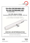
Kettenantrieb / Chain Drive
ELTRAL KS 30/40 Remote
Montage- und Bedienungsanleitung
Assembly and operating instructions
12.12.2008
2
Deutsch ........................................................................ 3
1.1
Allgemeine Angaben ..................................................... 3
1.2
Montagevorbereitungen ................................................ 7
1.3
Berechnung der Kraft zum Öffnen bzw. Schließen...... 7
1.4
Montage (mechanisch).................................................. 8
1.5
Installation (elektrisch) .................................................. 9
1.6
Betrieb / Bedienung..................................................... 10
1.7
Funkhandsender ......................................................... 11
1.8
Komponenten und Zubehör ........................................ 12
1.9
Wartung und Pflege..................................................... 12
1.10
Hilfe bei Störungen...................................................... 13
1.11
Demontage und Entsorgung ....................................... 14
1.12
Gewährleistung und Kundendienst............................. 14
1.13
Anschlussplan ............................................................. 15
English ....................................................................... 16
2.1
General information..................................................... 16
2.2
Preparing to install....................................................... 20
2.3
Calculation of force to open and close ....................... 20
2.4
Installation (mechanical) ............................................. 21
2.5
Installation (electrical) ................................................. 22
2.6
Operation / Control ...................................................... 23
2.7
Hand-held radio transmitter ........................................ 24
2.8
Components and accessories .................................... 25
2.9
Maintenance and care................................................. 25
2.10
Help in case of malfunctions ....................................... 26
2.11
Dismantling and disposal ............................................ 27
2.12
Warranty and customer service .................................. 27
2.13
Connection diagram .................................................... 28
3
Anwendungsdiagramm / Applikation chart............. 29
4
Anwendungsbeispiele / examples of use................ 30
5
Herstellererklärung / Manufacturer's declaration ... 31
2
9 Verwenden Sie nur Original-Ersatzteile, Original-Zubehör und Original-Befestigungsmaterial der
Fa. Gretsch-Unitas GmbH Baubeschläge.
1 Deutsch
9 Benötigtes Befestigungsmaterial ist mit dem Baukörper abzustimmen und wenn nötig zu ergänzen
1.1
Allgemeine Angaben
9 Prüfen Sie immer, ob Ihre Anlage den gültigen Bestimmungen entspricht. Besonders zu beachten
sind Öffnungsweite des Fensters, zulässige Einbaumaße, Öffnungsgeschwindigkeit, Druckkraft,
Querschnitt der Anschlussleitung in Abhängigkeit von Leitungslänge und Stromaufnahme.
Verwendete Symbole
Symbol
⇐
9
Signalwort
Gefahr !
Bedeutung
Warnung vor Personenschäden
Achtung !
Warnung vor Sachschäden
Hinweis !
Besondere Funktionen oder Anwendungstipps
Bestimmungsgemäße Verwendung
Handlungsaufforderung
Der Kettenmotor ELTRAL KS 30/40 Remote ist ausschließlich für das Öffnen und Schließen von Kipp, Klapp-, Dreh-, Dach-, Schwing-, und Wendefenstern vorgesehen. Eine andere oder darüber hinaus
gehende Verwendung gilt als nicht bestimmungsgemäß.
9 Der Antrieb ist ausschließlich zur Installation in trockenen Räumen bestimmt. Schützen Sie den
Antrieb dauerhaft vor Schmutz und vor Feuchtigkeit.
Grundlegende Hinweise
Die Montage- und Betriebsanleitung ist wichtiger Bestandteil der Lieferung und ist an die Personen
gerichtet, die den Motor montieren, betreiben oder warten. Die Anleitung enthält Informationen über
das Produkt und seine sichere Verwendung.
9 Bitte lesen Sie die Anleitung sorgfältig durch und beachten Sie insbesondere alle Hinweise, die die
Sicherheit betreffen.
9 Bewahren Sie die Anleitung auf.
9 Ein zuverlässiger Betrieb und ein Vermeiden von Schäden und Gefahren sind nur bei sorgfältiger
Montage und Einstellung nach der Montageanleitung gegeben.
Für Schäden, die durch andere Verwendung entstehen, haftet die Fa. Gretsch-Unitas GmbH Baubeschläge nicht.
Die Gewährleistung erlischt dadurch.
Beschreibung von ELTRAL KS 30/40 Remote
Der Kettenmotor ELTRAL KS 30/40 Remote ist zum Einsatz in trockenen Räumen bestimmt mit einer
maximal zulässigen Umgebungstemperatur von +65°C. Der Einbau kann sowohl in horizontaler als
auch in vertikaler Lage erfolgen.
9 Bei unsachgemäß durchgeführter Montage und Installation übernimmt die Fa. Gretsch-Unitas
GmbH Baubeschläge keine Haftung.
Eine Garnitur ELTRAL KS 30/40 Remote besteht aus:
9 Nach dem Entfernen der Verpackung ist zu prüfen, ob das Gerät vollständig und intakt ist. Plastikbeutel sowie Kleinteile wie Klammern etc. dürfen nicht in Reichweite von Kindern gelassen werden.
Sie stellen potentielle Gefahrenquellen dar.
• Standard-Schwenklager mit Abstandshalter
• Kettenantrieb mit Anschlusskabel, Länge 2m
• Schwenklager für Klappflügel mit Antriebsmontage am Rahmen
• Kippflügelbock für Rahmenmontage
• Klappflügelbock für Flügelmontage
Allgemeine Sicherheitshinweise
• Beutel mit Verschlussbügel und Verbindungsstift
9 Beachten Sie unbedingt die folgenden Sicherheitshinweise.
• Selbstklebende Bohrschablone
Zusätzliche Hinweise in den weiteren Kapiteln sind durch die oben beschriebenen Symbole auffällig
gekennzeichnet.
• Montage und Bedienungsanleitung
9 Lassen Sie die Montage, Installation und Erstinbetriebnahme nur von geschulten, sachkundigen
Personen durchführen.
⇐
Hinweis!
9 Beachten Sie alle für den Einsatzort geltenden Regeln und Bestimmungen, wie z.B.
Der Abstandhalter dient nur zur korrekten Positionierung. Er kann anschließend wieder entfernt werden.
- Arbeitsschutzvorschriften
- Unfallverhütungsvorschriften
Folgende Varianten der Montage sind möglich:
- VDE-Bestimmungen und DIN-Normen
• aufgesetzt auf dem Rahmen,
- „Richtlinie für kraftbetätigte Fenster, Türen und Tore“, BGR 232 der Berufgenossenschaft
(bei Bedarf bitte bei Fa. Gretsch-Unitas GmbH Baubeschläge anfordern)
• aufgesetzt auf dem Flügel,
- „Merkblatt KB.01: Kraftbetätigte Fenster“ des Verbandes der Fenster- und Fassadenhersteller
(VFF) (bei Bedarf bitte bei Fa. Gretsch-Unitas GmbH Baubeschläge anfordern)
9 Verwenden Sie den Motor nur in technisch einwandfreiem Zustand, bestimmungsgemäß, sicherheits- und gefahrenbewusst, unter Beachtung der Montage- und Betriebsanleitung.
⇐
Hinweis!
9 Bringen Sie Sicherheitseinrichtungen, wie z.B. Fangvorrichtungen oder Sicherheitsscheren sachgerecht an und stellen Sie sicher, dass diese funktionsfähig sind. Stellen Sie sicher, dass die Öffnungsweite der Fangvorrichtung für den Hub des Kettenantriebs ausreichend ist.
3
4
Typenschild
Das Typenschild ist auf dem Motor angebracht. Es ist in eingebautem
Zustand nicht mehr zu erkennen.
Kippflügel Flügelmontage / Klappflügel Rahmenmontage
Technische Daten für 1 Motor
Modell
110V / 230V
Schub / Zugkraft
* / max. 300N
Hub (einstellbar)
100, 200, 300, 400 mm
Nennspannung
110V / 230V~ 50Hz
Stromaufnahme bei Nennlast
Leistungsaufnahme bei Nennlast
Schubgeschwindigkeit (Volllast / 2/3-Last)
Doppelte elektrische Isolierung
0,12A
~28W
10 mm/s
ja
Betriebsart Einschaltdauer
30% (10min)
Umgebungstemperatur
-5 bis +65°C
Schutzart
Parallelschaltung mehrerer Antriebe
Endabschaltung bei Öffnung
IP30
Ja
Endabschaltung bei Schließung
Elektronisch mit Leistungsaufnahme
Überlastungsschutz bei Öffnung und Schließung
Elektronisch mit Leistungsaufnahme
Anschlusskabel
ca. 2m
Anschlusskabel
2 x 0,75 mm² - ca. 2m lang
Abmessungen (H x T x B)
Gewicht
Kippflügel Rahmenmontage
elektronisch
37 x 59 x 386,5 mm
Ca. 1,0 kg
Die Angaben in dieser Tabelle sind unverbindlich und können auch ohne Vorankündigung geändert
werden.
* Kraft-Weg-Diagramm
Entnehmen Sie die geeigneten Flügelhöhen für die unterschiedlichen Montagevarianten der folgenden
Tabelle oder den Diagrammen im Abschnitt 3
Min. Flügelhöhe
Hub
Hub
Hub
Hub
100 mm
200 mm
300 mm
400 mm
Kippflügel Rahmenmontage
250 mm
600 mm
1100 mm
1500 mm
Kippflügel Flügelmontage
200 mm
400 mm
650 mm
900 mm
Klappflügel Rahmenmontage
150 mm
250 mm
350 mm
450 mm
Montageart
⇐
Hinweis!
5
6
Kleinere Flügelhöhen
Bitte kontaktieren Sie uns, falls Sie die Montage an kleineren Flügelhöhen
vornehmen wollen.
1.2
Montagevorbereitungen
Personen- und Sachschäden durch unsachgemäßen Einsatz
Gefahr!
Stellen Sie mit Hilfe des Typenschildes am Motor und den in Abschnitt „1.1“
aufgeführten Technischen Daten sicher, dass Sie den für ihre Einbausituation
richtigen Motor vorliegen haben.
Achtung!
9 Untersuchen Sie die Lieferung sofort nach Erhalt auf etwaige Transportschäden. Bei Beschädigungen dürfen Sie den Motor nicht montieren.
⇐
Hinweis!
Bei Kippflügeln muss der Abstand der Innenseiten von Blendrahmen und Flügel mindestens 1 mm betragen damit ein sicheres Schließen gewährleistet ist. Bei flächenbündigen Fenstern
oder wenn die Innenseite des Flügels gegenüber dem Blendrahmen zurücksteht, muss bauseits um den entsprechenden Betrag
zwischen Kippflügelkonsole und Flügelprofil unterlegt werden.
F, Fg, Fk = Kraft zum Öffnen bzw. Schließen (N)
P = Flügelgewicht (kg)
2
A = Fensterfläche (m )
H = Flügelhöhe (mm)
C = Ausstellweite (mm)
Fw = Windlast
Für Dachfenster
Berechnung der Motorkraft in Abhängigkeit des Flügelgewichts P
F = 5,4 x P
Für senkrecht stehende Kipp- oder Klappfenster
Berechnung der Motorkraft in Abhängigkeit des Flügelgewichts P
Fg= 5,4 x P x C / H
Berechnung der Motorkraft in Abhängigkeit der Windkraft Fw
Fk = Fw x A / 2
Berechnung der Motorkraft in Abhängigkeit des Flügelgewichts und
Windkraft
1.3
⇐
Hinweis!
F= Fg + Fk
Berechnung der Kraft zum Öffnen bzw. Schließen
Mit den im Folgenden aufgeführten Formeln kann überschlägig ermittelt werden,
welche Kraft benötigt wird, um ein Fenster zu Öffnen bzw. zu Schließen.
Es wird von leichtgängigen Fenstern ausgegangen. Gegebenenfalls vorhandene
Schneelasten sind zusätzlich zu beachten.
1.4
Hinweis!
Höhe
Fw
0-8m
500N/m
2
8-20m
800N/m
2
20-100m
1100N/m
2
100<
1300N/m
2
m
Montage (mechanisch)
Gefahr
Gefahr!
⇐
Windlasten in Abhängigkeit der Gebäudehöhe
Die Anwendungsformel berücksichtigt nur Kipp-, Klapp- und Dachfenster. Die zulässige Motorkraft ist entsprechend den technischen Angaben im Abschnitt „1.1“ zu
entnehmen. Sollten Ihre errechneten Werte außerhalb der technischen max. Kraft
liegen, ist dies mit Gretsch-Unitas abzustimmen.
Nur geschulte, sachkundige Personen dürfen die Montage vornehmen.
Quetschgefahr
Beim automatischen Öffnen oder Schließen des Fensters entstehen Zug- und Druckkräfte bis
zu 300 N. Diese Kräfte können beim Hineingreifen zwischen Flügel und Rahmen Gliedmaßen
abquetschen. Insbesondere, da der Motor wiederholt versucht den Hub zu beenden.
9 Halten Sie Kinder, behinderte Personen oder Tiere von dem Fenster fern.
Gefahr!
9 Greifen Sie nicht zwischen Flügel und Rahmen, wenn der Motor läuft.
9 Sichern Sie bei einer Einbaulage des Fensterflügels unter 2,50 m alle Quetsch- und Scherstellen gegen unbeabsichtigtes Hineingreifen. Verfahren Sie dabei gemäß „Merkblatt des
VFF KB.01: Kraftbetätigte Fenster“.
7
8
Für den Anschluss des Motors ist ein zweiadriges (230V) Anschlusskabel erforderlich (siehe „Technische Daten“).
Verletzungsgefahr
Motorisch betätigte Kippfenster müssen Sie immer mit einer Fangsicherung ausrüsten sein, um
Verletzungen durch herunterschlagende Fenster zu verhindern.
Gefahr!
9 Beachten Sie den elektrischen Anschlussplan in Abschnitt „1.13“.
Auch bei der Montage am bereits eingebauten Fenster können Sie sich durch plötzlich aufklappende Fensterflügel verletzen.
9 Verwenden Sie Kabellängen, Kabelarten und Kabelquerschnitte entsprechend den Angaben des
Anschlussplans und den „Technischen Daten“.
9 Verwenden Sie geeignete Sicherheitseinrichtungen, wie z.B. Sicherungsscheren als Fangsicherung.
9 Stellen Sie sicher, dass die Kabel im Betrieb nicht abscheren, abknicken oder sich verdrehen. Ggf.
ist der Einsatz eines Kabelübergangs nötig.
9 Die Sicherheitsschere muss mit der Öffnungsweite des Antriebes abgestimmt sein. Die
Öffnungsweite der Sicherheitsschere muss um eine Blockade zu vermeiden, größer als der
Antriebshub sein.
9 Beachten Sie die Anschlussbelegung, die zulässige Antriebsspannung (vgl. Typenschild), die
minimale und maximale Leistungsangaben (vgl. technische Daten) und die Montage und Installationshinweise und halten Sie diese genau ein.
Gefahr von Montagefehlern
Achtung!
1.6
9 Achten Sie bei der Montage der Beschlagteile darauf, dass eine einwandfreie Funktion
gegeben ist.
Betrieb / Bedienung
LED-Anzeigen
9 Beachten Sie genau die beigefügten Einbauzeichnungen.
Die LED-Anzeige zeigt die verschiedenen Betriebszustände des Antriebes an. Sie sitzen vertieft auf
der Seite gegenüber dem Ausgang des Anschlusskabels.
9 Montieren Sie den Motor so, dass er jederzeit zugänglich ist.
9 Beachten Sie die Einbauzeichnung. Diese ist der Befestigungsgarnitur beigepackt bzw. kann über
die für Sie zuständige Niederlassung angefordert werden und enthält die entsprechenden Maßangaben in Abhängigkeit von der Montageart und vom Profilsystem.
9 Alle Maßangaben sind am Bau eigenverantwortlich zu prüfen und ggf. anzupassen.
Status der LED
ständig leuchtend
kurzes Aufblitzen
gleichmäßiges Blinken
leuchtend mit Dunkelblitz
Bedeutung
Antrieb in Betrieb
Antrieb hat den Endschalter in Offenstellung erreicht
Antrieb durch elektronische Lastabschaltung gestoppt
Antrieb in einer anormalen Position.
Er hat die Programmierung verloren.
Abschaltung in Schließstellung
9 Beachten Sie vor der Profilbearbeitung die folgenden Punkte:
- Mindestflügelbreite
In der Schließstellung schaltet der Antrieb über die integrierte Lastabschaltung ab. Es müssen daher
keine Endschalter eingestellt werden. Nach Erreichen der Endlage führt der Antrieb einen Rückhub
von ca. 1mm aus. Dadurch werden sowohl die Dichtungen als auch die Befestigungskonsolen entlastet.
- Mindestflügelhöhe
- maximales Flügelgewicht
- vorhandene Wind- und Schneelasten
- Platzbedarf am Profil unter Berücksichtigung der Montageart
Einstellung des Hubes
9 Kontrollieren Sie die erforderlichen Mindestabstände.
Werkseitig ist der Hub des Kettenantriebes auf 400mm eingestellt. Mit DIP-Schalter kann der Hub
jederzeit umgestellt werden. Sie liegen vertieft auf der dem Kabelaustritt gegenüberliegenden Seite.
Es müssen lediglich die DIP-Schalter 1 und 2 entsprechend der folgenden Tabelle umgelegt werden.
Damit die Änderung wirksam wird, muss die Kette ein kleines Stück ausgefahren und anschließen
wieder eingefahren werden.
9 Führen Sie eine Funktionsprüfung durch. Verwenden Sie dazu das passende GU Prüf - und Einstellgerät. (siehe Abschnitt „1.8 Komponenten und Zubehör“).
1.5
Abschließend sollte ein Probelauf durchgeführt werden.
Installation (elektrisch)
DIP-Schalter
Gefahr eines elektrischen Schlages
Die bauseitige Elektroinstallation darf nur eine zugelassene Elektrofachkraft vornehmen.
Gefahr!
9 Beachten Sie für die bauseitige Elektroinstallation die VDE-Vorschriften und die Vorschriften des örtlichen Netzbetreibers.
9 Schalten Sie alle stromführenden Teile frei, bevor Sie Arbeiten an der Installation oder der
Steuerung ausführen.
Gefahr von Zerstörung des Motors
Der Motor benötigt einen 230 V DC-Anschluss. Andere Spannungen zerstören den Motor.
Gefahr!
9 Schließen Sie den Motor entsprechend an.
9 Verlegen Sie das Motor-Anschlusskabel nicht zusammen mit einer Netzleitung.
Achtung!
9 24V DC-Antriebe niemals an 230V anschließen. Lebensgefahr!
9 Niederspannungsleitungen getrennt von Starkstromleitungen verlegen
9
10
Hub (mm
1
2
100
OFF
OFF
200
ON
OFF
300
OFF
ON
400
ON
ON
1.7
Funkhandsender
Der Kettenantrieb ELTRAL KS 30/40 REMOTE wird ausschließlich mit dem Funkhandsender KS
30/40 (Bestell-Nr. K-17439-00-0-0) bedient. Dieser Handsender besitzt 4 Tasten mit denen 4 Antriebe
unabhängig voneinander gesteuert werden können. Andererseits können jedem Antrieb bis zu 8
Handsender zugeordnet werden. Ein neunter Sender wird nicht mehr übernommen.
Die Funkübertragung arbeitet mit einer Übertragungsfrequenz von 433,92 MHz und mit einem variablen Code (“Rollcode“) mit 16 Milliarden Kombinationsmöglichkeiten. Der Code ändert sich bei jedem
Übertragungsvorgang nach einem Algorithmus, der den verwendeten Code verdeckt, so dass ein
optimales Maß an Sicherheit gewährleistet ist.
1.8
Komponenten und Zubehör
Kettenmotor ELTRAL KS 30/40 Remote
ELTRAL KS 30/40 - Remote
GU-Nr. K-17437-00-0-*
*= Farbtyp: 1 = grau (RAL7047); 6 = schwarz (RAL9005); 7 = weiß (RAL9016)
Zubehör für Kettenmotor ELTRAL KS 30/40 Remote
(Anwendungsbeispiele siehe Abschnitt 1.14)
Der Handsender ist bereits werkseitig mit einer Batterie ausgestattet und daher sofort funktionsfähig.
Funkhandsender
Zum Batteriewechsel den Handsender durch Herausdrehen der beiden Schrauben auf seiner Rückseite öffnen. Batterie entnehmen und durch eine neue Batterie gleichen Typs (Typ 23A, 12 V) ersetzen.
Die Programmierung des Senders bleibt dabei erhalten. Die entnommene Batterie ist gemäß den
gesetzlichen Bestimmungen der Wiederverwertung zuzuführen.
Klappflügelbock Befestigung horizontal GU-Nr. 9-44272-00-0-*
Speichern eines Funkhandsenders
ACHTUNG: Dieselbe Taste eines Handsenders kann nicht mehreren Antrieben zugeordnet werden.
1. DIP-Schalter 1 in Stellung ON umlegen, sodass die rote LED aufleuchtet. Anschließend den DIPSchalter sofort wieder auf OFF zurück stellen.
2. Die Taste auf dem Handsender, die dem Antrieb zugewiesen werden soll, solange
Btl. Klappflügelbock schmal
3. Sobald die LED am Antrieb zu blinken aufhört, ist die Programmierung abgeschlossen.
Speichern eines weiteren Handsenders wenn
die DIP-Schalter NICHT zugänglich sind
1. Gleichzeitig etwa eine Sekunde lang die Tasten 1, 2, 4
auf dem bereits eingespeicherten Handsender drücken,
dann die Taste betätigen, mit dem der Antrieb bedient
wird.
GU-Nr. K-17441-00-0-*
Btl. Schwenklager
GU-Nr. K-17440-00-0-*
Konsolensatz Flügelmontage
GU-Nr. K-17720-00-0-8
Prüf- und Einstellgerät
GU-Nr. K-17736-00-0-0
*= Farbtyp: 1 = grau (RAL7047); 6 = schwarz (RAL9005); 7 = weiß (RAL9016)
Fangsicherung Euro-Solid
Flügelhöhe
270 - 350 mm
351 - 500 mm
501 - 800 mm
801-1500 mm
betätigen, bis die LED am Antrieb aufblinkt.
GU-Nr. K-17437-00-0-0
GU-Nr.
6-27995-01-0-1
6-27995-03-0-1
6-27995-04-0-1
6-27995-05-0-1
9 Ggf. sind für den Einbau der Fangsicherungen profilbedingte Unterlagen notwendig
siehe Bestellkatalog.
9 Befestigungsgarnituren, abhängig von Montageart, Profilsystem und Profilmaterial
2. Die rote LED des Antriebes leuchtet auf.
3. Die Taste des neuen Handsenders drücken, die dem
Antrieb zugewiesen werden soll. Die LED des Antriebes
beginnt zu blinken, sobald die Taste des Handsenders
losgelassen wird.
1.9
Wartung und Pflege
Um einen störungsfreien Betrieb zu gewährleisten, müssen Sie die folgenden Arbeiten alle 1000
Öffnungszyklen durchführen jedoch mindesten einmal im Jahr:
4. Sobald die LED am Antrieb zu blinken aufhört, ist die
Programmierung abgeschlossen.
9 Prüfen Sie alle Schrauben auf festen Sitz und ziehen Sie diese nach, falls notwendig.
9 Kontrollieren Sie den optimalen Sitz des Fensterflügels im Fensterrahmen. Justieren Sie die Befestigungsgarnitur entsprechend.
9 Kontrollieren Sie alle Teile auf Beschädigungen und Verschleiß. Tauschen Sie, falls erforderlich,
die Teile aus.
9 Verwenden Sie keinesfalls Laugen oder Säuren zum Reinigen. Tauchen Sie das Gerät nicht in
Wasser ein.
9 Reparieren Sie bei einem Defekt den Antrieb nicht selbst. Entfernen Sie weder das Gehäuse noch
andere Teile. Wenden Sie sich bei Schäden am Gerät an den Hersteller. Es dürfen nur Ersatzteile
des Herstellers verwendet werden.
11
12
1.10 Hilfe bei Störungen
Die Reparatur eines defekten Motors ist beim Weiterverarbeiter oder beim Endanwender nicht sachgerecht möglich und daher nicht zulässig. Eine Reparatur kann nur im Herstellerwerk durchgeführt
werden. Falls Sie den Motor öffnen oder ihn manipulieren erlischt der Garantieanspruch.
1.11 Demontage und Entsorgung
Demontage
9 Tauschen Sie daher einen defekten Motor aus und lassen Sie ihn reparieren.
9 Falls der Motor stehen bleibt, prüfen Sie bitte, ob die Lastabschaltung aktiviert wurde.
Gefahr!
Treten bei der Installation oder im normalen Betrieb des Antriebes Probleme auf, kann mit Hilfe der
folgenden Tabelle Abhilfe geschaffen werden.
Beachten Sie die Sicherheitshinweise!
Achtung!
Problem
Möglich Ursache
Der Antrieb funktioniert
nicht
• Das Netzteil wird nicht mit
elektrischer Energie gespeist
• Anschlusskabel nicht angeschlossen oder ein loser
Draht
• Das Schaltnetzteil im Antrieb
ist defekt und stellt keine
Niederspannung bereit
• Zustand des FehlerstromSchutzschalter oder des
Sicherheitsschalters prüfen
Der Arbeitsablauf ist der gleiche, wie für die Montage beschrieben, jedoch in umgekehrter Reihenfolge. Die Einstellarbeiten entfallen.
• Alle Stromanschlüsse des
Antriebes kontrollieren
Entsorgung
• Antrieb austauschen
Motorbestandteile
⇐
•
Aluminium
•
Eisen
Die LED leuchtet auf, aber
der Antrieb funktioniert
nicht
• Der Antrieb wurde durch
Überspannung beschädigt
oder hat einen anderen Defekt
• Antrieb austauschen
Trotz der korrekten Einstellung findet der Antrieb
keinen Endschalter
• Die Programmierung wurde
nicht korrekt durchgeführt
• DIP-Schalter neu programmieren
• Störung oder Unterbrechung
des elektrischen DIPSchalterkontaktes
• Antrieb austauschen
9 Entsorgen Sie die Teile entsprechend den vor Ort gültigen gesetzlichen Vorschriften.
Der Antrieb läuft nicht an
• Der Funkhandsender ist vom
Empfänger nicht übernommen worden
• Die Abspeicherung des
Funkhandsenders wiederholen
1.12 Gewährleistung und Kundendienst
Hinweis!
•
Kunststoff
•
Kupfer
•
Zink
Grundsätzlich gelten unsere „Allgemeinen Geschäftsbedingungen“.
Reagiert der Motor nicht auf die Bedienung des Schalters/Tasters, lassen Sie bitte die elektrische
Versorgung durch eine Fachkraft überprüfen.
Die Gewährleistung entspricht den gesetzlichen Bestimmungen und gilt für das Land, in dem der
Motor erworben wurde.
Die Gewährleistung erstreckt sich auf Material- und Fertigungsfehler, die bei einer normalen Beanspruchung auftreten.
Gewährleistungs- und Haftungsansprüche bei Personen- und Sachschäden sind ausgeschlossen,
wenn sie auf eine oder mehrere der folgenden Ursachen zurückzuführen sind:
• Nicht bestimmungsgemäße Verwendung des Motors.
• Unsachgemäßes Montieren, Inbetriebnehmen, Bedienen, Warten und Reparieren des Motors.
• Betreiben des Motors bei defekten, nicht ordnungsgemäß abgebrachten oder nicht funktionsfähigen Sicherheits- und Schutzvorrichtungen.
• Nichtbeachten der Hinweise in der Montage- und Betriebsanleitung.
• Eigenmächtige bauliche Veränderungen am Motor.
• Katastrophenfälle durch Fremdkörpereinwirkung und höhere Gewalt.
• Verschleiß.
Ansprechpartner für eventuelle Gewährleistungen, oder wenn Sie Ersatzteile oder Zubehör benötigen,
ist die für Sie zuständige Niederlassung.
13
14
2 English
1.13 Anschlussplan
Anschluss für KS30/40 Remote
Der Kettenantrieb ELTRAL KS 30/40 - Remote besitzt ein ca. 2m langes zweiadriges Anschlusskabel.
Es muss an eine Netzspannung von 110V oder 230V~ 50Hz angeschlossen werden.
Die Steuerbefehle Öffnen und Schließen werden mit dem Funkhandsender KS 30/40 (Bestell-Nr. K17439-00-0-0) erteilt. Die Steuerung über einen fest verdrahteten Schalter oder Taster ist nicht möglich.
2.1
General information
Symbols used
Symbol
Der Anschluss des Antriebes ist nach dem folgenden Schaltbild vorzunehmen.
⇐
Signal word
Danger !
meaning
Warning of personal injury
Caution !
Warning of damage to property
Note !
Special functions or user tips
9
Instruction to do something
Basic advice
The Installation and Operating Guide is an important part of the supplied equipment, and is addressed
to the people who will install, operate or maintain the motor. The Guide tells you what you need to
know about the product and how to use it safely.
9
Please read the Guide carefully and pay particular attention to instructions concerning safety
9
Keep the Guide in a safe place.
9
Reliable functioning and prevention of risk and damage are only achieved with accurate assembly and setting according to the instructions.
9
In the event of incorrect mounting and installation, Gretsch-Unitas GmbH Baubeschläge accepts
no liability.
9
After removing all packaging, please verify that all parts of the appliance are present and intact.
Plastic bags and small parts such as clips etc. must be kept out of the reach of children as they
are potential sources of danger.
General safety instructions
9
It is absolutely essential to observe the following safety instructions.
9
Additional instructions in the further sections of the Guide are clearly identified by the symbols
referred to above.
9
Ensure that the mounting, installation and initial commissioning of the equipment is carried out by
trained and qualified persons only.
9
9
15
16
Observe all rules and regulations applicable at the place of installation, such as:
-
Health and safety regulations
-
Accident prevention regulations
-
VDE (German Electrical Engineers Association) regulations and DIN standards
-
The "Guidelines for Power-Operated Windows, Doors and Gates", BGR 232 of the Trade
Association (ask Gretsch-Unitas GmbH Baubeschläge for a copy if necessary)
-
"Leaflet KB.01: Power-Operated Windows" of the German Association of Window and Curtain Wall Manufacturers (VFF) (ask Gretsch-Unitas GmbH Baubeschläge for a copy
if necessary)
Use the motor only if it is in full technical working order, for the purpose for which it is designed,
in a safety-conscious way and with due regard to the dangers, and in accordance with the Installation and Operating Guide.
9
9
Attach safety devices such as safety catches or security stays correctly and ensure that they
work properly. Ensure that the opening distance of the catching device is sufficiently large to
match the stroke of the drive.
Use only original spare parts, original accessories and original fastening materials from GretschUnitas GmbH Baubeschläge.
Technical data for 1 motor
Modell
Pressing- / tensile force
Opening width (adjustable)
110V / 230V
* / max. 300N
100, 200, 300, 400 mm
9
Fixing material must be compatible with the structure and supplemented if required.
Rated voltage
9
Always verify if your appliance complies with the prevailing regulations. Special attention must be
paid to: opening distance of window, allowed installation dimensions, opening speed, pressure
force, cross section of connecting cable depending on cable length and current consumption.
Rated current consumption
0,12A
Power consumption
~28W
9
The drive is designed for the use in dry rooms only. Ensure that it is permanently protected
against moisture and dirt.
Run time (full load / 2/3-load)
110V / 230V~ 50Hz
10 mm/s
Double electrical insulation
yes
Duty ratio (power-on time)
30% (10min)
Approbiate Use
Ambient temperature
-5 to +65°C
The ELTRAL KS 30/40 Remote chain motor is designed for the automatic opening and closing of tilt,
top hung, side hung, horizontal and vertical pivot windows, roof-lights and small domes exclusively.
Any other use is considered unintended use.
Protection class
IP30
Connection of several drives in parallel
yes
Gretsch-Unitas GmbH Baubeschläge is not liable for damage caused by unintended use.
The warranty shall be null and void in consequence.
Limit switch stop at opening
electronic
Limit switch stop at closing
electronic with power input
Overload protection at opening and closing
electronic with power input
Connecting cable
2 x 0,75 mm² approx. 2 m
Description of ELTRAL KS 30/40 Remote
dimensions Height x Depth x Width
The chain motor ELTRAL KS 30/40 Remote is designed for use in dry rooms with a maximum ambient
temperature of +65°C. It can be installed either horizontally or vertically.
Weight
One ELTRAL KS 30/40 Remote kit consists of:
The specifications stated in this table are not binding and may be changed without notice.
•
Chain drive with connecting cable, length 2 m
•
Standard bracket with distancer
•
Bracket for soffit mounting of top hung sash
•
Chain holder for tilt sash
•
Chain holder for top hung sash
•
Package with locking piece and connecting pin Ø4x32
•
Self-adhesive drilling template
•
Assembly and operating instructions
⇐
* Load-displacement diagram
Serving as positioning aid only, the distancer may be removed afterwards.
Note!
The following installation variants are possible:
•
mounted on the frame,
•
mounted on the sash.
⇐
9 Note!
Rating plate
The rating plate is attached to the motor. With the motor installed, the
rating plate is not visible.
17
18
37 x 59 x 386,5 mm
approx. 1,0 kg
Tilt window sash mounting / top hung window frame mounting
2.2
Preparing to install
Danger!
Incorrect use may cause injury to people and damage to property
Refer to the type label of the motor and the technical data in section "2.1" to
ensure that you have the correct motor for your installation situation.
Caution!
9
Examine the delivered equipment immediately upon receipt and check it for transport damage.
Do not install the motor if it is damaged.
⇐
tilt window frame mounting
Note!
To determine the installation variant depending on the sash height, refer to the following table or the
charts in section 3:
2.3
⇐
Note!
Min. sash high
Installation method
stroke
100 mm
stroke
200 mm
stroke
300 mm
stroke
400 mm
tilt window frame mounting
250 mm
600 mm
1100 mm
1500 mm
Tilt window sash mounting
200 mm
400 mm
650 mm
900 mm
top hung window frame mounting
150 mm
250 mm
350 mm
450 mm
⇐
Note!
⇐
Note!
Smaller sash heights
Please contact us if smaller sash heights are required.
19
20
With tilt sashes, the clearance between frame and sash profile
must be at least 1 mm in order to provide for safe closing of the
window. If frame and sash profiles are flush, or if the sash profile
stands back from the frame profile on the interior side, it is necessary to underlay the tilt sash bracket accordingly.
Calculation of force to open and close
With the formulae indicated below it is possible to determine the approximate force required to
open or close a (smooth-running) window;
Possible snow loads are to be considered.
The application formula considers tilt and top hung windows only. The maximum rated drive
force is to be taken from the technical data you will find in section „2“. If the values you calculated exceed the max. allowed force, please contact Gretsch-Unitas GmbH Baubeschläge.
Risk of injury
Motorised tilting windows must always be equipped with a safety catch to prevent injury due to
falling sashes.
Danger!
Also with the motor being mounted on a window already installed, you may be injured by the
sash opening suddenly.
9
Use appropriate safety devices such as security stays to catch the window.
9
The safety device must be adapted to the stroke of the drive. To avoid a blockade, the
opening width of the safety device must be larger than the drive stroke.
Risk of installation errors
Caution!
F, Fg, Fk = opening / closing force (N)
P = sash weight (kg)
2
A = window area (m )
H = sash high (mm)
C = opening distance of sash (mm)
Fw = wind load
For light domes or horizontally installed windows
Calculating the drive force of depending on the sash weight P
Install the motor in such a way that it is always accessible.
Follow the installation drawing which is enclosed in the fastening kit or can be ordered by your
responsible distribution company. The drawing contains all dimensions depending on the installation method and the profile system.
9
All dimensions of the particular location are the responsibility of the installer.
For vertically installed tilt or top hung windows
Calculating the drive force depending on the sash weight P
Calculating the drive force depending on the wind load Fw
Fk = Fw x A / 2
Calculating the drive force depending on the sash weight Fg and the
wind load Fw
F= Fg + Fk
height
Fw
0-8m
500N/m
2
8-20m
800N/m
2
20-100m
1100N/m
2
100<
1300N/m
2
m
Follow the enclosed installation drawings exactly.
9
F = 5,4 x P
Wind load in dependence
on the building height
When installing fittings, verify their faultless functioning.
9
9
9
Fg= 5,4 x P x C / H
9
Before working on the profiles, take note of the following:
-
Minimum sash width
-
Minimum sash height
-
Maximum sash weight
-
Possible wind- and snow loads
-
Space required on the profile according to the installation method
9 Check the required minimum distances.
9 Carry out a function test. Use the appropriate Gretsch-Unitas testing and setting apparatus for this
purpose (see section "2.7 Components and accessories").
2.5
Installation (electrical)
Risk of electric shock
2.4
Electrical installation on site must be carried out by a qualified electrician only.
Installation (mechanical)
Danger!
Danger!
Danger!
Installation must only be carried out by trained and qualified personnel.
Keep children, disabled people and animals away from the window.
9
Do not reach between sash and frame when the motor is running.
9
In the case of a window sash installed below 2.50 m, secure all crushing and shearing
points to ensure that people do not accidentally reach into them. Observe VFF leaflet
KB.01: "Power-Operated Windows"..
9
Disconnect mains supply before carrying out any work on the installation or the control unit.
The motor requires a 230 V connection. Other voltages will destroy the motor.
During the automatic opening or closing of the window, push and pull forces of up to 300 N
occur. These forces can crush limbs when reaching between sash and frame, especially since
the motor repeatedly tries to complete the lift.
9
For electrical installation on site observe VDE (German Electrical Engineers Association)
regulations and the requirements of the local mains supplier.
Risk of destroying the motor
Crushing hazard
Danger!
9
Danger!
Caution!
21
22
9
9
9
9
Connect the motor accordingly.
Do not lay the motor connecting cable together with a mains wire
Never connect 24 V DC drives to 230 V ! Danger of life !
Low-voltage lines and power lines must be wired separately.
A three-core (230V) connecting cable is required to connect the motor (see "Technical Data").
2.7
9
Follow the electrical connection diagram in section "2.12 Connection diagram “.
9
For cable lengths, cable types and cable cross-sections observe the details in the connection
diagram and the "Technical Data".
The chain drive ELTRAL KS 30/40 REMOTE is controlled exclusively with the hand-held radio transmitter KS 30/40 (order no. K-17439-00-0-0). This transmitter is provided with 4 buttons controlling 4
drives independently from each other. Vice versa, up to 8 transmitters may be allocated to each drive.
A ninth sender is not accepted.
9
Make sure that the cables are prevented from being cut, kinked or twisted. If necessary use cable
ducts.
The radio transmitter operates at a frequency of 433,92 MHz and with a variable code (“rollcode”)
allowing for 16 billion combinations. At each transmission, the code changes according to an algorithm
hiding the code used, thus guaranteeing utmost security.
9
Verify the correct terminal assignment, the supply voltage (see type label) and the minimum and
maximum ratings (see technical data). Carefully adhere to all assembly details given.
Delivered with a battery, the hand-held transmitter is serviceable from the start. For a battery change
open the transmitter by removing the two screws on the back. Replace the old battery by a new one of
the same type (23 A, 12 V). During battery change, the transmitter’s programming is stored. Dispose
the used battery according to the prevailing legal recycling regulations.
2.6
Operation / Control
Storing a hand-held radio transmitter
LED indication
ATTENTION: One and the same button of a hand-held transmitter cannot be allocated to several
drives.
1. Set DIP switch 1 to position ON, the red LED will light up. Immediately hereafter set the DIP switch
to position OFF again.
2. Press the button on the transmitter which you want to allocate to the drive until the LED on the drive
flashes.
3. As soon as the LED on the drive stops flashing, the programming is terminated.
The LED indicates the drive’s different modes of operation. It is located on the opposite side of the
connecting cable outlet.
Status of LED
Constantly lit
Off and flashing
Regular blinking
On and flashing
Hand-held radio transmitter
Meaning
Drive in operation
Drive has reached the linit Stopp in open position
Drive is stopped by the electronic load interruption.
Drive is in abnormal position; programming lost
Storing a further hand-held transmitter with
the DIP switches NOT being accessible
Switch-off in closed position
Thanks to the integral load interruption, the drive switches off in closed position. Setting the limit switch
is the refore not required. When the end position is reached, the drive carries out a reverse stroke of
approx. 1 mm. Thus relieving both gaskets and holding brackets.
Setting the stroke
The factory setting of the stroke is 400 mm; it can be changed via DIP switches at any time. The DIP
switches 1 and 2, positioned on the opposite side of the cable outlet, have to be set according to the
following table.
1. Press buttons 1, 2, 4 of the hand-held transmitter already
stored for about one second, then press the button with
which the drive is operated.
2. The LED of the drive will light up.
3. Press the button on the new hand-held transmitter to be
allocated to the drive. The LED on the drive will start
flashing as soon as the button on the transmitter is released.
5. As soon as the LED on the drive stops flashing,
4. the programming is terminated.
In order to make a change effective, it is necessary to extend the chain a little bit and retract it again.
After changing the stroke, a test run should be carried out.
DIP-switch
stroke (mm
1
2
100
OFF
OFF
200
ON
OFF
300
OFF
ON
400
ON
ON
23
24
2.8
Components and accessories
2.10 Help in case of malfunctions
Installers or end-users must not repair a faulty motor themselves. Professional repair can only be
carried out by the manufacturer. If you open the motor or manipulate it in any way, the warranty shall
be null and void.
Chain drive ELTRAL KS 30/40 Remote
ELTRAL KS 30/40 Remote
GU- No. K-17437-00-0-*
*= color: 1 = grey (RAL7047); 6 = black (RAL9005); 7 = white (RAL9016)
Accessories for chain drive ELTRAL KS 30/40 Remote
Therefore you should replace a faulty motor and have it repaired.
9
If the motor stops, check whether the limit position switch is activated.
In case any problems arise during installation or operation of the drive, please consult the following
table for possible help:
(examples of use see section 2.14)
Hand-held radio transmitter
9
GU- No. K-17439-00-0-0
Chain holder for top hung sash
GU- No. 9-44272-00-0-*
Problem
Possible cause
Solution
package chain holder for top hung sash - small
GU- No. K-17441-00-0-*
Drive not functioning
• Mains adapter without current
supply
• Check state of fault current
protection switch or safety
switch
• Connecting cable unplugged
or wire(s) loose
• Check all electrical connection of drive
• Switching mains adapter in
the drive damaged, not providing low voltage.
• Exchange drive
LED lit but the drive not
working
• Drive damaged as a result of
overvoltage or other destruction
• Exchange drive
Limit stop not functioning
• Programming not carried out
correctly
• Repeat programming of DIP
switch
• Failure of the electrical DIP
switch contact.
• Exchange drive
• Hand-held radio transmitter
not accepted by the receiver
• Repeat storage of handheld transmitter.
Package bracket
GU- No. K-17440-00-0-*
Bracket set sash mounting
GU- No. K-17720-00-0-8
Testing and setting apparatus
GU- No. K-17736-00-0-0
*= color: 1 = grey (RAL7047); 6 = black (RAL9005); 7 = white (RAL9016)
Security stay Euro-Solid
Sash height
270 - 350 mm
351 - 500 mm
501 - 800 mm
801-1500 mm
G.U No.
6-27995-01-0-1
6-27995-03-0-1
6-27995-04-0-1
6-27995-05-0-1
Drive not starting.
9
The installation of the security stay may require a profile-related base plate. See catalogue.
9
Fastening kits vary depending on installation method, profile system and profile material
If the motor does not respond to operation of the switch/button, have the power supply checked by
a qualified person.
2.9
Maintenance and care
To ensure a problem-free operation, you must perform the following jobs after every 1.000 opening
cycles, however, at least once a year:
9
Check all screws to ensure they are tight and retighten them if necessary.
9
Check if the window sash is seated perfectly in the window frame. Adjust fixings if necessary.
9
Check all parts for damage and wear. Replace parts where necessary.
9
Never use acidic or basic cleaning agents. Do not immerse the appliance in water.
9
Do not try to repair the drive yourself in case of failure. Do not remove the casing or other parts.
In case of signs of damage to the appliance contact the manufacturer. Only spare parts supplied
by the manufacturer may be used for repair.
25
26
2.11 Dismantling and disposal
2.13 Connection diagram
Dismantling
Connection of KS30/40 Remote
The chain drive ELTRAL KS 30/40 REMOTE comes with a 2 mtr two-core supply cable which is to be
connected to a mains voltage of 230 V ~ 50 Hz.
Danger!
The commands OPEN and CLOSE are given with the hand-held radio transmitter KS 30/40 (order no.
K-17439-00-0-0). Control via hard-wired switch is not possible.
Observe the safety instructions!
The connection is to be carried out according to the following wiring diagrams.
Caution!
For dismantling the appliance proceed as described under "Installation", however, in reverse order.
Settings are irrelevant.
Disposal
⇐
Note!
Motor components
•
Aluminium
•
Iron
•
•
•
Plastic
Copper
Zinc
Dispose of the parts in accordance with the local disposal regulations.
2.12 Warranty and customer service
Our "General Terms of Business" apply in principle.
The warranty complies with legal regulations and is valid in the country where the motor was
purchased.
The warranty covers material and manufacturing defects occurring under normal stress.
Warranty and liability claims in view of personal injury and damage to property are excluded, if the
latter have occurred as a result of
9
Inappropriate use of the motor
9
Improper installation, commissioning, operation, maintenance and repair of the motor
9
Operation of the motor with faulty, incorrectly fitted or non-functional safety and protection devices
9
Failure to observe the instructions in the Installation and Operating Guide
9
Unauthorised structural modification of the motor
9
Catastrophic events due to penetration of foreign bodies and force majeure.
9
Wear
For possible warranty claims or the delivery of spare parts or accessories, please contact your responsible distribution company.
27
28
3 Anwendungsdiagramm / Applikation chart
4 Anwendungsbeispiele / examples of use
Der Anwendungsbereich der Motoren ist eine
Empfehlung der Fa. Gretsch-Unitas GmbH
Baubeschläge und kann je nach Profilsystem
variieren.
The application range of the drives is a recommendation of Gretsch-Unitas GmbH
Baubeschläge and may vary depending on the
profile system.
Die Produktinformationen der Systemhersteller,
insbesondere Informationen zu Konstruktion und
Verarbeitung, Dichtigkeit, zu max. Flügelgewichte sowie zu Materialeigenschaften, wie z. B.
Längenausdehnung von Profilen, sind zu beachten.
The product guidelines of the profile manufacturers regarding construction, assembly, max. sash
dimensions, max. sash weights and material
qualities (e.g. longitudinal expansion) are to be
observed.
29
30
5 Herstellererklärung / Manufacturer's declaration
ý
Gretsch-Unitas GmbH
Baubeschläge
Johann-Maus-Str. 3
D-71254 Ditzingen
www.g-u.de
M-00159-00 - Ausgabe 3 - 12/2008 - Änderungen vorbehalten
31
32