1
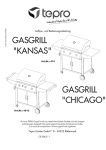
Technik, die Vertrauen schafft!
Bedienungsanleitung
Instruction Manual
Elektro - Kammeröfen
Electric Front - loading Kilns
KE - N
Stand: 03/2004
KE - S
Technik, die Vertrauen schafft!
INHALTSVERZEICHNIS
Seite
1.
Vorwort................................................................................................. 3
2.
Übersicht Modellreihe KE – N............................................................. 4
3.
Übersicht Modellreihe KE – S............................................................. 4
4.
4.1.
4.2.
4.3.
Wichtige Sicherheitshinweise............................................................ 5
Allgemeine Anmerkungen...................................................................... 5
Sicherheitshinweise............................................................................... 5
Sicherheitshinweise für den Einsatz...................................................... 5
5.
5.1.
5.2.
5.3.
5.4.
5.5.
5.6.
5.7.
5.8.
5.9.
5.10.
Inbetriebnahme.................................................................................... 6
Anlieferung / Ofen auspacken............................................................... 6
Verpackung entsorgen........................................................................... 6
Betriebsumgebung / Aufstellort.............................................................. 6
Aufbau des Brennofens......................................................................... 7
Brennofen auf Füße stellen................................................................... 7
Abluft installieren....................................................................................8
Zuluftschieber........................................................................................ 8
Netzanschluss / Regelanlage anschließen............................................ 9
Montage der Regelanlage................................................................... 10
Ofen einbrennen / Besatz einbrennen................................................. 10
6.
6.1.
6.2.
Allgemeine Bedienungshinweise..................................................... 12
Bedienungshinweise Regelanlage....................................................... 12
Richtiger Umgang beim Brand............................................................. 13
7.
7.1.
7.2.
Weiteres Zubehör.............................................................................. 13
Trockenaufsatz.................................................................................... 13
Besatzgestell....................................................................................... 14
8.
Wartung / Pflege / Reinigung............................................................ 14
9.
Tipps zur Störungssuche.................................................................. 15
10.
Garantiebestimmungen..................................................................... 16
11.
Schutzrechte / Markennamen / Haftungsausschluss..................... 17
12.
GS-Prüfbescheinigung /
EG-Konformitätserklärung......................................................18/19/20
13.
Ofenpass / Ersatzteile........................................................................21
Stand: 03/2004
Seite 2 von 54
14.
14.1.
14.2.
14.3.
14.4.
Anschlussplan / Schaltplan.............................................................. 22
Anschlussplan AMP KE – N................................................................ 22
Schaltplan KE – N...........................................................................23/24
Anschlussplan AMP KE – S................................................................. 25
Schaltplan KE – S........................................................................... 26/27
15.
Service - Adressen............................................................................ 54
1. VORWORT
Herzlichen Glückwunsch, Sie haben sich für einen ROHDE - Brennofen entschieden,
einem Markenprodukt für höchste Ansprüche.
Dieser Kammerofen ist das Ergebnis intensiver Weiterentwicklung kleinerer und mittlerer
Keramikbrennöfen. Das Resultat ist ein 1300 / 1320°C Ofen mit reduktionsbeständiger
Innenauskleidung für Anwendungen in der Keramik- und Glasbearbeitung.
Diese Bedienungsanleitung soll Ihnen das Kennenlernen Ihres ROHDE - Kammerofens
vereinfachen. Aus diesem Grund haben wir einige wichtige Hinweise und Richtlinien
zusammengefasst, um Ihnen einen einfachen und sicheren Umgang mit Ihrem
Brennofen zu ermöglichen.
Bitte lesen Sie vor der ersten Benutzung des ROHDE - Kammerofens die Bedienungsanleitung sorgfältig durch.
Lernen Sie die Funktionsweisen Ihres Kammerofens und der Regelanlage kennen.
Stand: 03/2004
Seite 3 von 54
deutsch
Technik, die Vertrauen schafft!
Technik, die Vertrauen schafft!
2. Übersicht Modellreihe KE – N
3. Übersicht Modellreihe KE – S
Stand: 03/2004
Seite 4 von 54
Technik, die Vertrauen schafft!
deutsch
4. WICHTIGE SICHERHEITSHINWEISE
4.1. Allgemeine Anmerkung
Beachten
Sie
unbedingt
die
Sicherheitshinweise
aber
auch
die
Sicherheitskennzeichen, um mögliche Gefährdungen ausschließen zu können. Lesen
Sie die folgenden Sicherheitshinweise in Ihrem eigenen Interesse vollständig durch,
bevor Sie den Brennofen in Betrieb nehmen.
Bewahren Sie die Bedienungsanleitung sorgfältig auf. Verwenden Sie zu Ihrer eigenen
Sicherheit ausschließlich ROHDE - Ersatzteile!
4.2. Sicherheitshinweise
Achtung:
Heiße Oberfläche, nicht in
heißem Zustand öffnen!
Achtung: Hochspannung Lebensgefahr!
Achtung: Vor Öffnen des
Elektrokastens bitte
Netzstecker ziehen!
Diese Produktreihe erhielt
von der Berufsgenossenschaft das Zertifikat „GS
geprüfte Sicherheit“.
Das CE - Zeichen bestätigt, dass das Konformitätsbewertungs-Verfahren
nach EG-Richtlinien durchgeführt wurde.
4.3. Sicherheitshinweise für den Einsatz
Nur unter Einhaltung der folgenden Sicherheitshinweise kann ein gefahrloser Betrieb
des ROHDE – Brennofens ermöglicht werden:
•
Bei Gewerbebetrieben sind der Brennofen und die Regelanlage vor der ersten
Inbetriebnahme und im Zeitabstand von 4 Jahren durch eine Elektrofachkraft auf
ordnungsgemäßen und einwandfreien Zustand nach „BGV A2 Prüfung“ zu
prüfen.
•
Reparatur und Wartungsarbeiten an elektrischen Bauteilen dürfen nur durch eine
Elektrofachkraft durchgeführt werden.
•
Aus Sicherheitsgründen muss vor Wartungsarbeiten der Netzstecker gezogen
werden.
•
Es darf kein Verlängerungskabel verwendet werden!
Stand: 03/2004
Seite 5 von 54
Technik, die Vertrauen schafft!
5. INBETRIEBNAHME
5.1. Anlieferung / Ofen auspacken
Wird der ROHDE - Kammerofen auf Palette mit Spedition geliefert, ist in jedem Fall die
Sendung sofort bei der Anlieferung auf sichtbare Beschädigungen der Verpackung zu
prüfen. Ist dies der Fall, packen Sie die Palette zusammen mit dem Fahrer aus und
prüfen die Ware erneut auf Beschädigungen. Vermerken Sie evtl. Schäden sofort auf
dem Lieferschein und lassen Sie den Fahrer unbedingt gegenzeichnen. Behalten Sie
eine Kopie der Schadensreklamation. Melden Sie die Beschädigung sofort der
Transportfirma. Spätere Reklamationen sind zwecklos.
5.2. Verpackung entsorgen
Bringen Sie die Holz-, Karton- und Folienverpackung zu einer entsprechenden
Entsorgungsstelle und helfen Sie mit, aktiv den Umweltschutz zu fördern. Weitere
Informationen zum Entsorgen der Verpackungen erhalten Sie von Ihrem Händler oder
der Gemeinde, bzw. Stadtverwaltung.
5.3. Betriebsumgebung / Aufstellort
Wählen Sie einen geeigneten Aufstellort, beachten Sie dabei unbedingt folgende Regeln
und bereiten Sie den Aufstellort entsprechend vor:
•
Stellen Sie den Brennofen auf eine ebene Fläche.
•
Der Abstand zu Wänden sollte an allen Seiten mindestens 25 cm betragen.
•
Der Boden, Deckenisolierung, Wände, Trennwände, Verkleidungen etc. müssen
aus schwer entflammbarem Material sein.
•
Achten Sie darauf, dass der Aufstellort gut belüftbar ist. Andernfalls muss eine
Abluftanlage installiert werden. Fragen Sie hierzu in jedem Fall einen
Lüftungstechniker.
Stand: 03/2004
Seite 6 von 54
Technik, die Vertrauen schafft!
deutsch
5.4. Aufbau des Brennofens
Kontrollieren Sie zunächst das mitgelieferte Zubehör:
4 Cordierit – Klötzchen
1 Metallplatte für die Regelanlage
1 Abluftstutzen (alle Bild 1)
und 2 Beinpaare zum Aufstellen des
Brennofens, sowie Regelanlage mit
Bedienungsanleitung.
Bild 1
Die Regelanlage inkl. Bedienungsanleitung sowie die Bedienungsanleitung zum Brennofen sind ebenfalls beigelegt.
5.5. Brennofen auf Füße stellen
Sollte der Kammerbrennofen nicht bereits durch den ROHDE Liefer- und Aufstellservice
auf die Füße gestellt worden sein, ist es nun an der Zeit, den Brennofen aufzustellen.
Mit Hilfe eines Hubstaplers können Sie den Kammerofen anheben. Führen Sie die
Gabeln vorsichtig unter der Brennofentür in Richtung Rückwand ein.
Achten Sie darauf, dass das Stromanschlusskabel und die AMP-Steckdose nicht
beschädigt werden!
Heben Sie den Brennofen auf eine Höhe an, in der Sie die Beinpaare leicht auf die
Zapfen schieben können.
Achtung: Bitte die farbigen Markierungen
(Bild 2) beachten: rot zu rot und grün zu
grün!
Bild 2
Befestigen Sie die Beinpaare mit den vorhandenen Inbus-Schrauben am Brennofen und
senken Sie den Brennofen am gewünschten Brennofenplatz ab.
Stand: 03/2004
Seite 7 von 54
Technik, die Vertrauen schafft!
5.6. Abluft installieren
Lösen Sie zuerst die beiden Schrauben für den Abluftstutzen. Schrauben Sie den
mitgelieferten Abluftstutzen (Bild 3) an die dafür vorgesehenen Bohrungen auf der
Rückseite des Brennofens. Die Befestigungsstelle ist so gewählt, dass austretende
Dämpfe und Gase durch einen Abluftschlauch (optionales Zubehör) abgeleitet werden.
Der Abluftschlauch wird in den Abluftstutzen gesteckt und mit der Fixierschraube im
Stutzen befestigt.
Bild 3
5.7. Zuluftschieber
Alle Modelle der Rohde - Kammeröfen verfügen über einen Zuluftschieber (Bild 4) am
Boden des Ofens. Ist der Zuluftschieber in voller Länge eingeschoben (Bild 4), so ist die
Luftzuführung geschlossen. Wenn der Schieber vollständig herausgezogen wird, ist die
Zuluftöffnung geöffnet (Bild 5).
Bild 4
Bild 5
Sie erhöhen die Lebensdauer der Heizwendeln erheblich, wenn die Zu- und
Abluftöffnungen beim Brennen bis ca. 600 - 700° C geöffnet sind.
Stand: 03/2004
Seite 8 von 54
5.8. Netzanschluss / Regelanlage anschließen
Der Ofen ist mit einem Anschlusskabel für Netzanschluss ausgestattet. Die
entsprechenden Daten können dem Typenschild entnommen werden. Die
Stromzuführung muss dem Brennofen entsprechend ausgelegt und in unmittelbarer
Nähe des Brennofens sein. Verwenden Sie keinesfalls ein Verlängerungskabel! Das
Zuleitungskabel darf den heißen Ofen nicht berühren.
Spannungsschwankungen sind örtlich möglich. In Deutschland kann die Nennspannung
von 400 Volt um 10 % schwanken. Das führt zu einer Abweichung in der Nennleistung.
Fällt die Spannung unter Last auf 360 Volt ab, so sinkt die Ofenleistung um ca. 16 %.
Ist das Gebäudenetz durch einen Fehlerstromschutzschalter abgesichert, so muss auch
der Brennofen über einen Fehlerstromschutzschalter mit 0,03 A Nennstrom abgesichert
und betrieben werden.
Bild 6
Bild 7
Die Regelanlage (Bild 6) wird über eine 14-polige Steckschraubverbindung an den
Brennofen gekoppelt. Die dafür vorgesehene schwarze Steckdose (Bild 7) am Ofen
befindet sich neben der elektrischen Zuleitung an der Rückseite des Brennofens.
Stecken Sie bitte zuerst den schwarzen Regelungsstecker ein. Eventuell müssen Sie
den Stecker etwas drehen, bis er einrastet. Dann den Verschraubungsring festdrehen
und damit den Stecker sichern.
Stand: 03/2004
Seite 9 von 54
deutsch
Technik, die Vertrauen schafft!
Technik, die Vertrauen schafft!
5.9. Montage der Regelanlage
Montage am Brennofen
Platzieren Sie die mitgelieferte Reglerplatte (Bild 9) so, dass Sie die beiliegende
Sterngriffschraube in die dafür vorgesehene Stelle (Bild 8) eindrehen können. Ist die
Reglerplatte fest angeschraubt, können Sie die Regelanlage auf der Reglerplatte (Bild 10)
befestigen. Eine genaue Montageanweisung finden Sie in der Bedienungsanleitung Ihrer
Regelanlage!
Bild 8
Bild 9
Bild 10
Montage an der Wand
Wählen Sie einen sicheren, gut bedienbaren Platz neben dem Ofen an der Wand. Die
Befestigungselemente der Regelanlage abnehmen. Die Befestigungsteile mit 2 Dübeln
und 2 Schrauben an der Wand befestigen. Jetzt kann die Regelanlage von oben in die
jeweilige Halterung gesteckt werden.
5.10. Ofen einbrennen / Besatzmaterial einbrennen
ACHTUNG: Entfernen Sie nun unbedingt die Styroporplatten, welche als
Transportsicherung und Schutz der SIC – Bodenplatte dienen.
Bevor der Ofen in den täglichen Gebrauch geht, sollte ein Trockenbrand gefahren
werden. Das „Einbrennen“ ist zum einen nötig, um Restfeuchtigkeit aus der Ofenwand
zu entfernen, zum anderen wird durch dieses „Einbrennen“ eine schützende
Oxydschicht auf den Heizwendeln erzeugt, welche die Lebensdauer der Heizwendeln
entscheidend verlängert.
Brennkurve für das Einbrennen:
•
•
•
Aufheizen mit 100°C/h
Endtemperatur 1050° C
Haltezeit 1 Std. 30 Min.
Hierbei sollte das rückseitige Abluftloch und die Zuluftöffnung nicht verschlossen
werden!
Beachten Sie bitte, dass das Offenlassen des Abluftlochs bis ca. 600-700° C, auch bei
den zukünftigen Bränden, die Lebensdauer der Heizwendeln erheblich erhöht.
Stand: 03/2004
Seite 10 von 54
Zeitgleich mit dem Einbrennen des Brennofens können Sie das Einbrennen der
Hohlstützen und Besatzplatten (optionales Zubehör) vornehmen.
Platzieren Sie die mitgelieferten Cordierit-Klötzchen (Bild 11) auf den Boden des
Brennofens, legen Sie dann eine erste Besatzplatte (optionales Zubehör) mittig darauf
(Bild 12). Beachten Sie, dass seitlich und an der Rückwand gleichmäßige Abstände zur
Wandmauerung vorhanden sind, damit die Bodenheizung nicht in der
Wärmeabstrahlung behindert wird.
Zu empfehlen ist eine 4-Punkt-Auflage der Besatzplatten, wobei jeweils Stütze über
Stütze stehen sollte (Bild 13). Ansonsten werden die Platten auf Biegung beansprucht,
was immer wieder zu Verformungen oder Riss der Besatzplatten führt.
Eine zu nahe an die Heizwendeln gesetzte Platte ist stark rissgefährdet. Es sollten mind.
20 mm Abstand zur Spirale eingehalten werden.
Bild 11
Stand: 03/2004
Bild 12
Seite 11 von 54
Bild 13
deutsch
Technik, die Vertrauen schafft!
Technik, die Vertrauen schafft!
6. ALLGEMEINE BEDIENUNGSHINWEISE
6.1. Bedienung der Regelanlage
Bitte lesen Sie zunächst die entsprechende Betriebsanleitung für Ihre Regelanlage
sorgfältig durch! Nach dem Anschließen der Netzleitung sowie der Regelungszuleitung
ist der Ofen betriebsbereit.
Typische Brennkurven am Beispiel einer Regelanlage TR 305
°C
T2
t2
R2
R1
R3
T1
T3
Ende
t
°C/h
°C
°C/h
°C
°C/h
Std./min.
°C
Brand
R1 - °C/h
T1 - °C
R2 - °C/h
T2 - °C
t2 Std./min.
R3 - °C/h
T3 - °C
Schrühbrand
100
600
250
900
00:10
Pass
---
Glasurbrand
150
300
350
1150
00:20
Pass
---
Stand: 03/2004
Seite 12 von 54
6.2. Richtiger Umgang beim Brand
•
Keine brennbaren Gegenstände in unmittelbarer Nähe legen.
•
Der Brennofen darf nur in einem gut belüftbaren Raum aufgestellt und betrieben
werden. Um einen zuverlässigen Betrieb des Brennofens zu gewährleisten, darf
der Ofen nur bis zu einer Umgebungstemperatur von 40°C betrieben werden.
•
Der Brennofen muss frei stehen. Die Wärmeabstrahlung darf nicht behindert
werden. Legen Sie keine Gegenstände auf oder am Ofen ab.
•
Öffnen Sie keinesfalls den Brennofen, solange er noch in Betrieb oder nicht
vollständig abgekühlt ist. Hohe, austretende Temperaturen führen zu Brand- und
Verletzungsgefahr sowie zu vorzeitigem Verschleiß des Ofens.
•
Brennen Sie Materialien, welche gesundheitsschädliche Gase und Dämpfe
entwickeln, ist es unbedingt erforderlich, eine Abluftanlage zu installieren und
diese ins Freie umzuleiten.
•
Brennen Sie niemals brennbare Materialien oder Lebensmittel im Ofen.
7. WEITERES ZUBEHÖR
7.1. Trockenaufsatz
Der Trockenaufsatz (Bild 14) in eine interessante Ergänzung für Schulen, Werkstätten etc.
Für jeden Kammerofen kann der Aufsatz individuell angepasst und aufgesetzt werden.
Sie schaffen sich damit drei großzügige Ebenen zum Trocknen der Keramikwaren.
Bild 14
Stand: 03/2004
Seite 13 von 54
deutsch
Technik, die Vertrauen schafft!
Technik, die Vertrauen schafft!
7.2. Besatzgestell
Das Besatzgestell (Bild 15) erlaubt es Ihnen vor allem, die größeren Keramikbrennöfen
„Herdwagenlike“ zu beschicken. Das Gestell wird außerhalb des Ofens mit dem
gewünschten Besatz versehen, dann setzt man diesen mittels eines Hubwagens sanft
auf die ersten Stützen in den Ofen.
Bild 15
8. WARTUNG / PFLEGE / REINIGUNG
Achten Sie darauf, dass keine Tone und Glasuren an die Heizelemente gelangen. Dies
führt unweigerlich bei den nächsten Bränden zum Ausfall der Wendel. Sollten dennoch
Verunreinigungen an den Heizelemente gelangen, entfernen Sie diese sofort, da
eingebrannte Glasuren etc. die Heizelemente und die Steine beschädigen. Sprechen Sie
bei größeren Schäden mit uns oder Ihrem Fachhändler.
Heizwendeln sind Verschleißteile. Ihr Widerstand (Ohm) erhöht sich bei jedem Brand
und führt im Laufe der Zeit zu Verzögerungen der Brennkurve durch Leistungsabfall, vor
allem im oberen Temperaturbereich. Wir empfehlen bei fortgeschrittenem Verschleiß
üblicherweise den Austausch der kompletten Heizwendeln, da einzeln ausgetauschte
Heizwendeln zu Temperaturdifferenzen innerhalb des Ofens führen können.
Lassen Sie die Heizwendeln durch eine Elektrofachkraft tauschen!
Ein Tipp für den Brenn-Profi:
Legen Sie sich einen kompletten Satz Heizwendeln auf Reserve!
Dies verhindert unnötigen Stress im Notfall und sichert Ihnen unverzügliche
Brennfortsetzung.
Stand: 03/2004
Seite 14 von 54
Reinigen Sie den Brennofen mittels Besen und Staubsauger regelmäßig von Ton- bzw.
Steinstaub. So verlängern Sie auch die Lebensdauer Ihrer Heizwendeln.
Vermeiden Sie nach Möglichkeit reduzierende Glasurbrände, da diese zum Abbau der
Oxydationsschicht führen und somit die Lebensdauer der Heizwendeln erheblich
verkürzen.
9. TIPPS ZUR STÖRUNGSSUCHE
Die Regelanlage kann nicht eingeschaltet werden.
•
Überprüfen Sie, ob die Regelanlage am Schaltkasten des Ofens eingesteckt
wurde.
•
Prüfen Sie weiterhin, ob der Brennofen am Stromanschluß angeschlossen ist.
•
Überprüfen Sie die Feinsicherung am Stromkasten des Brennofens. Diese ist mit
T 2A abgesichert.
•
Lassen Sie Ihre Hausanschlüsse (Stecker), Sicherungen und die Stromaufnahme des Brennofens durch eine Elektrofachkraft prüfen.
Die Regelanlage zeigt eine Fehlermeldung zwischen „F1“ und „F9“ an.
Hierzu können Sie in der Bedienungsanleitung für die Regelanlage die entsprechende
Vorgehensweise finden.
Der Brennraum erwärmt sich nicht.
Überprüfen Sie die Funktion des Deckelschalters. Vermutlich arbeitet der Türschalter
nicht und somit kann der Sicherheitsschütz nicht schalten.
Der Brennofen heizt nur sehr langsam.
Die eingegebenen Temperaturen werden nicht erreicht. Die Regelanlage zeigt eine
Fehlermeldung. Überprüfen Sie die Heizleiter auf evtl. sichtbaren Bruch.
Alle ROHDE-Brennöfen wurden vor Verlassen der
Produktionsstätte eingeschaltet und auf Funktion geprüft!
Stand: 03/2004
Seite 15 von 54
deutsch
Technik, die Vertrauen schafft!
Technik, die Vertrauen schafft!
10. GARANTIEBESTIMMUNGEN
Wir garantieren einwandfreie Verarbeitung und Funktion des gelieferten Brennofens und
gewähren 36 Monate Garantie ab Rechnungsdatum.
Ausgenommen von der Garantie sind neben den Heizwendeln (Verschleißteile) folgende
Punkte:
• Vom Kunden verursachte Beschädigungen.
• Beschädigungen, die vom Brenngut verursacht wurden, z. B. durch Überschreiten der
maximalen Temperatur.
• Beschädigungen durch unsachgemäße(n) Transport(e).
• Beschädigungen durch nicht für den Ofen zulässige chemische Reaktionen während
des Brandes (z. B. Salzbrand).
• Ausschluss jeglicher Haftung des Herstellers bei unsachgemäßem Umgang und
damit entstandenen Schäden.
Wichtig: Die GARANTIEKARTE (zu finden auf der letzten Seite) bitte sofort ausgefüllt
zurücksenden! Beachten Sie bitte: Ohne die eingesandte Garantiekarte ist eine
kostenlose und schnelle Bearbeitung im Schadensfall nicht möglich.
Achtung: Die Feuerleichtsteine der Ausmauerung sind starken Temperaturschwankungen ausgesetzt. Dadurch können Haarrisse in der Steinausmauerung entstehen. Dieser Vorgang ist normal und beeinträchtigt nicht die Funktion des Ofens. Sie
sind daher auch kein Anlass für eine Reklamation.
Was tun im Garantie-/Schadensfall:
Informieren Sie bitte Ihren Fachhändler – und zwar bevor etwaige Kosten entstehen. Ihr
Fachhändler entscheidet nach Rücksprache mit uns, dem Hersteller, was weiter zu tun
ist.
Geben Sie bitte im Falle einer Reklamation den Ofen-Typ, die Produkt-Nr. und das
Kaufdatum bzw. Baujahr an (siehe Typenschild seitlich am Ofen).
Stand: 03/2004
Seite 16 von 54
11. SCHUTZRECHTE / MARKENNAMEN /
HAFTUNGSAUSSCHLUSS
Der Inhalt dieser Bedienungsanleitung dient ausschließlich Informationszwecken, kann
ohne Vorankündigung geändert werden und ist nicht als Verpflichtung der Helmut Rohde
GmbH anzusehen. Wir geben keine Garantie oder Gewähr hinsichtlich der Richtigkeit
oder Genauigkeit der Angaben in dieser Bedienungsanleitung.
Die Wiedergabe von Gebrauchsnamen, Handelsnamen, Warenbezeichnungen usw. in
dieser Bedienungsanleitung erfolgt ohne besondere Kennzeichnung, da diese allgemein
bekannt sind. Diese Namen und Bezeichnungen können jedoch Eigentum von Firmen
oder Instituten sein.
Stand: 03/2004
Seite 17 von 54
deutsch
Technik, die Vertrauen schafft!
Technik, die Vertrauen schafft!
12. GS-PRÜFBESCHEINIGUNG / KONFORMITÄTSERKLÄRUNG
Stand: 03/2004
Seite 18 von 54
deutsch
Technik, die Vertrauen schafft!
Stand: 03/2004
Seite 19 von 54
Technik, die Vertrauen schafft!
Stand: 03/2004
Seite 20 von 54
13. OFENPASS / ERSATZTEILE
Im hinteren Teil dieser Bedienungsanleitung finden Sie den Ofenpass für Ihren
gekauften Brennofen. Dieser Ofenpass beinhaltet alle ofenrelevanten Daten, welche für
eine rasche und genaue Ersatzteilbestellung erforderlich sind.
Halten Sie bei Ersatzteilbestellungen immer Ihren Ofenpass und Ihre Kaufrechnung griffbereit.
Stand: 03/2004
Seite 21 von 54
deutsch
Technik, die Vertrauen schafft!
Technik, die Vertrauen schafft!
14. ANSCHLUSSPLAN / SCHALTPLAN
14.1. Anschlussplan AMP KE – N
Stand: 03/2004
Seite 22 von 54
Technik, die Vertrauen schafft!
Stand: 03/2004
deutsch
14.2. Schaltplan KE – N
Seite 23 von 54
Technik, die Vertrauen schafft!
Stand: 03/2004
Seite 24 von 54
deutsch
Technik, die Vertrauen schafft!
14.3. Anschlußplan AMP KE - S
Stand: 03/2004
Seite 25 von 54
Technik, die Vertrauen schafft!
14.4. Schaltplan KE – S
Stand: 03/2004
Seite 26 von 54
deutsch
Technik, die Vertrauen schafft!
Stand: 03/2004
Seite 27 von 54
Technology you can rely on!
TABEL OF CONTENTS
page
1.
Preface....................................................................…………............. 29
2.
Overview model series KE – N............................................………...30
3.
Overview model series KE – S............................................………... 30
4.
4.1.
4.2.
4.3.
Important safety instructions..............................................………...31
General information................................................................………...31
Safety instructions..................................................................………... 31
Safety instructions for operation.................................…….....………...31
5.
5.1.
5.2.
5.3.
5.4.
5.5.
5.6.
5.7.
5.8.
5.9.
5.10.
Initial operation...................................................................…………. 32
Delivery / removal of packing material...................................………... 32
Disposal of packing material..................................................………... 32
Operation environment / place of operation...........................………... 32
Mounting of kiln.............................................................………………. 33
Mounting the kiln on its legs...................................................………...33
Install exhaust fume system...................................................………... 34
Air supply regulator................................................................………... 34
Mains supply / connect kiln controller................................….………... 35
Mounting of the controller.......................................................………...36
Burn in the kiln / burn in furniture.....................................…………….. 36
6.
6.1.
6.2.
General instructions for operation.....................................………... 38
Instructions for controller operation........................................………... 38
Instructions for correct firing................................................………….. 39
7.
7.1.
7.2.
Further equipment................................................................……….. 39
Drying attachment...................................................................……….. 39
Furniture carriage.....................................................................………. 40
8.
Maintenance / cleaning................................................……………… 40
9.
Tips for trouble shooting.....................................................………...41
10.
Guarantee regulations.........................................................………... 42
11.
Industrial property rights / trade names
disclaimer..............................................................…………………… 43
12.
GS certificate of inspection /
EG declaration of conformity....................................………...44/45/46
13.
Kiln passport / spare parts...................................................………. 47
Stand: 03/2004
Page 28 von 54
14.
14.1.
14.2.
14.3.
14.4.
Connecting diagram / circuit diagram..................................……… 48
Connecting diagram AMP KE – N............................................……….48
Circuit diagram KE – N.......................................................………. 49/50
Connecting diagram AMP KE – S...........................................……….. 51
Circuit diagram KE – S.........................................................………52/53
15.
Service contact details...........................................................……… 54
1. PREFACE
Congratulations! You have opted for a ROHDE kiln – a high-quality product for highest
requirements.
This front loading kiln is the result of our intense research in the improvement of small to
medium sized ceramic kilns. It is suitable for firing glass and ceramics up to 1200 /
1320°C and is equipped with a reduction resistant lining.
This instruction manual will make it easy for you to get familiar with your new ROHDE
front loading kiln. We have compiled a collection of important information and guidelines
in order to make operating your ROHDE kiln as safe and simple as possible.
Please read the instruction manual carefully, before you use your ROHDE front loading
kiln for the first time.
Get familiar with the features and functions of the front loading kiln and the controller.
Stand: 03/2004
Page 29 von 54
english
Technology you can rely on!
Technology you can rely on!
2. Overview model series KE – N
3. Overview model series KE – S
Stand: 03/2004
Page 30 von 54
Technology you can rely on!
4. IMPORTANT SAFETY INSTRUCTIONS
Please make sure that you understand both the safety instructions and the safety icons,
in order to eliminate potential danger. It is in your own interest to read through the
following safety instructions very carefully before you start operating your kiln.
Always keep your instruction manual in a safe place. To your own safety use only
ROHDE spare parts!
4.2. Safety instructions
Caution:
Hot surface, do not open
while kiln is hot!
Caution: high voltage danger!
Caution: Disconnect
power plug before
opening the switch box!
This product series was
granted the GS safety
certificate by the German
trade association.
The CE icon confirms that the conformity to EC standards has been
tested.
4.3. Safety instructions for operation
The safe operation of a ROHDE kiln will only be possible by adhering to the following
safety instructions:
•
For industrial use a qualified electrician must check if both kiln and controller are
in proper and perfect condition prior to first operation and in periods of 4 years
(BGV A2 inspection).
•
Repair and maintenance of electric components must be carried out by a
qualified electrician.
•
For safety reasons the power plug must be disconnected before carrying out
maintenance or repair work.
•
Do not use extension cords!
Stand: 03/2004
Page 31 von 54
english
4.1. General information
Technology you can rely on!
5. INITIAL OPERATION
5.1. Delivery / removal of packing material
If the ROHDE front loading kiln is delivered on pallet by freight forwarding, please check
the delivery immediately for damages. Should you find any damages on the packing,
unpack the pallet together with the driver and check the product for any damages. Write
down any damages found on the delivery note and do not forget to have the note
countersigned by the driver. Keep a copy of the damage complaint. Notify the forwarding
agent immediately about the damage. We regret that later claims cannot be accepted.
5.2. Disposal of packing material
Please contribute to a clean environment by disposing of the wood, cardboard and
plastic packing material in your nearest recycling centre. For further information on the
disposal of packing material please contact your retailer or community council.
5.3. Operation environment / place of operation
When you choose a suitable place for your kiln, please take note of the following
guidelines and prepare the kiln environment accordingly:
•
Place the kiln on an even surface.
•
The distance to the walls should be at least 25 cm on each side.
•
Floor, insulations of the ceiling, walls, dividing walls, panelling, etc have to be
made of material which is not easily flammable.
•
Make sure that the environment of the kiln can be aired properly. If this is not the
case a ventilation system has to be installed. Please consult a qualified
ventilation specialist to find out if a ventilation system is necessary.
Stand: 03/2004
Page 32 von 54
Technology you can rely on!
5.4. Mounting of kiln
At first you should check the enclosed accessories:
english
4 cordierite blocks
1 metal plate for the controller
1 exhaust fume socket (all in picture 1)
2 leg pairs on which to mount the kiln, and
the controller including the instruction
manual for the controller.
picture 1
You will also find enclosed the two instruction manuals for the controller and the kiln as
well as the controller itself.
5.5. Mounting the kiln on its legs
In case the front loading kiln has not already been mounted on its legs by our ROHDE
delivery and assembly service you should now proceed to do so.
Use a fork lift to lift the front loading kiln from the ground. Carefully guide the fork under
the kiln door towards the back wall of the kiln.
Make sure that you do not damage neither the power cord nor the AMP plug!
You should lift the kiln high enough to make sure that you can push the leg pairs easily
onto the respective hubs.
Caution: Please follow the coloured
markings (picture 2): red with red and green
with green!
picture 2
Fix the legs onto the kiln with the enclosed Allen screws and lower the kiln at the desired
operation place.
Stand: 03/2004
Page 33 von 54
Technology you can rely on!
5.6. Install exhaust fume system
First loosen the two screws for the exhaust fume socket. Screw the enclosed exhaust
fume socket (picture 3) onto the supplied drill hole at the rear side of the kiln. The location
of the opening has been chosen in a way that will allow for the vapour and gases to be
released through an exhaust fume tube (optional accessory). Please plug the exhaust
fume tube into the exhaust fume socket and fix it to the socket with the fixing screw.
picture 3
5.7. Air supply regulator
All models of ROHDE front loading kilns are equipped with an air supply regulator
near the floor. The air supply is closed, when the regulator is inserted full length
(picture 4) and opened when the regulator is pulled out entirely (picture 5).
(picture 4)
picture 4
picture 5
You can significantly increase the service life of the heating elements by opening the air
supply and the exhaust fume opening up to a temperature of 600-700°C
Stand: 03/2004
Page 34 von 54
Technology you can rely on!
5.8. Mains supply / connect kiln controller
Regional voltage fluctuations are possible and will lead to fluctuations in the nominal
output. If the voltage drops from 230 to 210 under load, the output of the kiln will be
reduced by 16%.
If the power grid of the building is protected with a residual current circuit-breaker, the
kiln too has to be protected and operated with a residual current circuit-breaker with
0.03 A rated current.
picture 6
picture 7
The controller (picture 6) is connected to the kiln with a 14-pin plug-and-screw connection.
You will find the black plug (picture 7) for this connection next to the electric connection on
the rear side of the kiln. Please plug in the black plug of the controller. You might need to
turn it a little bit until it locks in place. Then fasten the connection ring, in order to protect
the connection.
Stand: 03/2004
Page 35 von 54
english
The kiln is equipped with a mains supply cord. The properties of the supply are stated on
the type plate. The power supply has to be suitable for the requirements of the kiln and
the plug must be located next to the kiln. Do not use extension cords! The mains supply
cord may not make contact with the hot kiln.
Technology you can rely on!
5.9. Mounting of the controller
Mounting of the controller onto the kiln
Place the enclosed controller plate (picture 9) onto the kiln so that you can screw the
enclosed star-grasping screw into the supplied drill hole (picture 8). Once the controller
plate is fastened onto the kiln wall you can fasten the controller onto the plate (picture 10).
Please find the precise instructions for the mounting of the controller in your controller
instruction manual.
picture 8
picture 9
picture 10
Mounting the controller on the wall
Please choose a protected and easily accessible position on the wall next to the kiln.
Detach the fixation elements from the controller. Mount the fixation elements with two
wall plugs and two screws onto the wall. Now you can push the controller from above
into the fixation elements.
5.10. Burn in the kiln / burn in furniture
CAUTION: Please remove the polystyrene plates which have protected the SIC
base plate during transport.
Before you start using your kiln for regular service you should run a firing with the empty
kiln. The “burning-in” is necessary to eliminate the remaining moisture from the kiln walls
and to produce a protective oxide layer on the heating elements, which will significantly
increase their service life.
Power settings for the process of “burning-in”:
•
•
•
heat up with 100°C/h
end temperature 1050° C
dwell time 1 h. 30 min.
Please do not close the exhaust fume opening on the rear side of the kiln or the air
supply!
Please note that the service life of the heating elements will be prolonged significantly,
when you do not close the exhaust fume opening up until 600-700°C, in the first as well
as in future firing processes.
Stand: 03/2004
Page 36 von 54
Technology you can rely on!
Place the enclosed cordierite blocks (picture 11) on the bottom of the kiln, then place a first
shelf (optional accessory) on top (picture 12). Please make sure that the distance of the
shelf to the side and back walls of the kiln is equal on all sides to allow for free heat
radiation of the base heating.
We recommend to support the shelf in 4 points. You should always aim to place one stilt
on top of the other (picture 13), unless the shelves might be bent and consequently suffer
from deformation or cracking.
Do not place the shelves to close to the heating elements as this might cause cracks in
the shelf. The distance to the heating spiral should be at least 20 mm.
picture 11
Stand: 03/2004
picture 12
Page 37 von 54
picture 13
english
While firing the kiln you can also burn-in the hollow stilts and additional shelves (optional
accessories).
Technology you can rely on!
6. GENERAL INSTRUCTIONS FOR OPERATION
6.1. Instructions for controller operation
Please read the applicable instructions for your controller carefully first! After connecting
the mains supply cord as well as the controller the kiln is ready for operation.
Example for a typical firing cycle with a TR 305 controller
°C
T2
t2
R2
R1
R3
T1
T3
Ende
t
°C/h
°C
°C/h
°C
°C/h
h./min.
°C
Firing
R1 - °C/h
T1 - °C
R2 - °C/h
T2 - °C
t2 Std./min.
R3 - °C/h
T3 - °C
biscuit firing
100
600
250
900
00:10
Pass
---
gloss firing
150
300
350
1150
00:20
Pass
---
Stand: 03/2004
Page 38 von 54
Technology you can rely on!
•
Do not place flammable objects near the kiln.
•
The kiln may be placed and operated only in well aired rooms.To guarantee
reliable operation, the kiln may be operated only up to a surrounding temperature
of 40°C.
•
The kiln may not make contact with any other object. Make sure that the heat
release is not blocked. Do not place objects on top of or around the kiln.
•
Never open the kiln during operation or before it has entirely cooled down. Heat
released from the kiln might cause damage and injuries and leads to premature
wear of the kiln.
•
When firing materials which release hazardous gases and fumes it is essential
that you install an exhaust fume system which directs the exhausts into the open
air.
•
Never place flammable materials or food in the kiln.
7. FURTHER EQUIPMENT
7.1. Drying attachment
The drying attachment (picture 14) is an interesting additional feature for kilns used in
schools, workshops etc. For each front loading kiln the attachment can be individually
adjusted and mounted. It will supply you with three spacious levels for drying your
ceramic products.
picture 14
Stand: 03/2004
Page 39 von 54
english
6.2. Instructions for correct firing
Technology you can rely on!
7.2. Loading carriage
The loading carriage (picture 15) makes it possible to charge especially larger kilns in batch
oven fashion. Just load your ceramic goods onto the carriage outside the kiln first, then
place it carefully onto the first stilts in the oven using a hand lift.
picture 15
8. MAINTENANCE / CLEANING
Please take care that no clays or glazings make contact with the heating elements. This
would result in the failure of the elements during the next firing. Should nevertheless the
heating elements be stained by any substance please clean them immediately, as
burned-in glazings etc. will damage the heating elements and bricks. In the case of
substantial damage please contact us or your retailer.
Heating elements are subject to wear. Their resistance (Ohm) increases with every
firing. In the course of time this will lead to delay in the firing cycle due to a drop in
output, especially in the upper temperature range. In the case of excessive wear we
recommend to replace all, rather than only individual heating elements, as individually
replaced elements might lead to differences in temperature within the kiln.
Consult a qualified electrician for the replacement of the heating elements!
A tip for the firing professional:
Store a complete set of additional heating elements! In case of an emergency this
will spare you unnecessary delay and will enable you to continue firing as quickly
as possible.
Stand: 03/2004
Page 40 von 54
Technology you can rely on!
Remove clay and stone dust regularly using a broom and a vacuum cleaner. This will
also increase the service life of your heating elements.
9. TIPS FOR TROUBLE SHOOTING
The controller cannot be switched on.
•
Check if the controller has been connected to the switch box of the kiln.
•
Check if the kiln is connected to the mains supply.
•
Check the micro-fuse on the switch box of the kiln. It is fused with T 2A.
•
Have your house mains supplies (plugs), fuses and the current consumption of
your kiln checked by a qualified electrician.
The controller displays an error message between “F1” and “F9”.
You will find the respective approach described in your users manual for the controller.
The firing chamber does not heat.
Check if the lid switch is working. Probably the door switch is not working and thus it
cannot operate the safety contactor.
The kiln heats very slowly.
The kiln does not reach the chosen temperature. The controller displays an error
message. Check the heating elements for visible damage.
Each ROHDE kiln is switched on and checked for
function before it leaves our factory!
Stand: 03/2004
Page 41 von 54
english
If possible refrain from reduction gloss firing, as it contributes to the decomposition of the
oxidation layer and which will reduce the service life of the heating elements
significantly.
Technology you can rely on!
10. GUARANTEE REGULATIONS
We guarantee the faultless workmanship and function of the delivered kiln and grant a
36-month guarantee.
Along with the heating elements (subject to wear and tear) the following instances are
excluded from the guarantee:
• Damages which have been caused by the customer.
• Damages which have been caused by the fired material, e.g. due to exceeded
temperature limits.
• Damage caused by inappropriate transport(s).
• Damages due to chemical reactions during firing for which the kiln is not designed
(e.g. salt glazed ceramics).
• The manufacturer is not liable for any damage caused by inappropriate operation and
resulting damages.
Important: Please fill in the GUARANTEE CARD and send it back immediately! Please
note: If you do not send back the Guarantee Card, we will not be able support you
quickly and free of charge in an event of damage
Caution: The fire bricks of the lining are exposed to heavy temperature fluctuations. This
can cause crazings in the firebrick lining. This process is normal and does not affect the
functions of the kiln. It therefore cannot be a reason for reclamation.
What to do in the event of guarantee/damage:
Please notify your retailer - before any costs arise. Your retailer will then talk to us, the
manufacturer, how to proceed.
In the case of a reclamation, please state the kiln type, product number and the date
of purchase or the year of construction (see type plate on the kiln side).
Stand: 03/2004
Page 42 von 54
Technology you can rely on!
The content of the instruction manual are purely informative. It may be changed without
prior notice and may not be seen as a liability of Helmut Rohde GmbH. We do not
guarantee or take over responsibility for the correctness or precision of the contents in
this instruction manual.
We mention names, trade names, product identifications etc. without special
identification, as they are commonly known. Those names and identifications, however,
may be the property of companies or institutes.
Stand: 03/2004
Page 43 von 54
english
11. INDUSTRIAL PROPERTY RIGHTS / TRADE NAMES /
DISCLAIMER
Technology you can rely on!
12. GS CERTIFICATE OF INSPECTION /
DECLARATION OF CONFORMITY
Fachausschüsse Seine und Erden/
Glas und Keramik
Prüf- und Zertifizierungsstelle
im BG-PRÜFZERT
Hauptverband der gewerblichen
Berufsgenossenschaften
GS Test Certificate
Translation
01008
No. of certificate
Name and address of the
holder of the certificate:
(customer)
Helmut Rohde GmbH
Name and address of the
manufacturer:
Bamham 18, D-83134 Prutting
Name and address of the
place of manufacture:
siehe oben
Ref. of customer:
KE N
Ref. of Test and Certification Body:
FA 612.18 + F 506 Kr/We
Date of Issue:
30.07.2001
Product designation:
Kilns for ceramics
Type:
KE 80 S, KE 90 N, KE 150 N, KE 200 N, KE 250 N, KE 330 N, KE 480 N, KE 600 N
Intended purpose:
Electric frontloaders for firing ceramic products up to 1300 °C
Testing based on:
DIN EN 60335-1:10.95 (DIN VDE 0700 Teil 1:02.81)
DIN VDE 0700 Teil 244:05.87
Remarks:
The type tested meets the requirements specified in article 3 para. 1 of the Equipment Safety Act (GSG, 3, Abs. 1).
Thus, the type tested also complies with the provisions laid down in the directive 73/23/EEC (Electrical Equipment), amended by
the directive 93/68/EEC.
The holder of the certificate is entitled to affix the GS-mark shown overleaf to the products complying with the type tested.
At that, the holder of the certificate shall observe the conditions specified overleaf.
The present certificate including the right to affix the GS-mark will become invalid at the latest on:
30.07.2006
Further provisions concerning the validity, the extension of the validity and other conditions are laid down in the Rules of
Procedure for Testing and Certification of October 1997.
......................................................................
Signature ()
PZB03E
12.98
Postal adress:
Postfach 10 15 40
30836 Langenhagen
Office:
Theodor-Heuss-Str. 160
30853 Langenhagen
Phone: (05 11) 72 57 - 0
Fax: (05 11) 72 57 - 791
In any case, the German original shall prevail.
Stand: 03/2004
Page 44 von 54
Technology you can rely on!
Fachausschüsse Seine und Erden/
Glas und Keramik
Prüf- und Zertifizierungsstelle
im BG-PRÜFZERT
GS Test Certificate
Translation
99020
No. of certificate
Name and address of the
holder of the certificate:
(customer)
Helmut Rohde GmbH
Name and address of the
manufacturer:
Bamham 18, D-83134 Prutting
Name and address of the
place of manufacture:
siehe oben
Ref. of customer:
Rohde
Ref. of Test and Certification Body:
FA 612.18 + F 506 Kr/We
Product designation:
Kilns for ceramics
Type:
KE 130 S, KE 180 S, KE 230 S, KE 300 S, 450 S
Intended purpose:
Electric frontloaders for firing ceramic products up to 1320 °C
Testing based on:
DIN EN 60335-1:10.95 (DIN VDE 0700 Teil 1:02.81)
DIN VDE 0700 Teil 244:05.87
Date of Issue:
16.12.1999
Remarks:
The type tested meets the requirements specified in article 3 para. 1 of the Equipment Safety Act (GSG, 3, Abs. 1).
Thus, the type tested also complies with the provisions laid down in the directive 73/23/EEC (Electrical Equipment), amended by
the directive 93/68/EEC.
The holder of the certificate is entitled to affix the GS-mark shown overleaf to the products complying with the type tested.
At that, the holder of the certificate shall observe the conditions specified overleaf.
The present certificate including the right to affix the GS-mark will become invalid at the latest on:
31.12.2004
Further provisions concerning the validity, the extension of the validity and other conditions are laid down in the Rules of
Procedure for Testing and Certification of October 1997.
......................................................................
Signature ()
PZB03E
12.98
Postal adress:
Postfach 10 15 40
30836 Langenhagen
Office:
Theodor-Heuss-Str. 160
30853 Langenhagen
Phone: (05 11) 72 57 - 0
Fax: (05 11) 72 57 - 791
In any case, the German original shall prevail.
Stand: 03/2004
Page 45 von 54
english
Hauptverband der gewerblichen
Berufsgenossenschaften
Technology you can rely on!
Stand: 03/2004
Page 46 von 54
Technology you can rely on!
13. KILN PASSPORT / SPARE PARTS
When ordering spare parts please have your kiln passport and your invoice of
purchase ready at any time.
Stand: 03/2004
Page 47 von 54
english
On the last pages of this instruction manual you will find the kiln passport for your
purchased kiln. This kiln passport displays all the relevant data which will ensure the
quick and precise ordering of spare parts.
Technology you can rely on!
14. CONNECTING DIAGRAM / CIRCUIT DIAGRAM
14.1. Connecting diagram AMP KE – N
Stand: 03/2004
Page 48 von 54
Technology you can rely on!
english
14.2. Circuit diagram KE – N
Stand: 03/2004
Page 49 von 54
Technology you can rely on!
Stand: 03/2004
Page 50 von 54
Technology you can rely on!
english
14.3. Connecting diagram AMP KE - S
Stand: 03/2004
Page 51 von 54
Technology you can rely on!
14.4. Circuit diagram KE – S
Stand: 03/2004
Page 52 von 54
english
Technology you can rely on!
Stand: 03/2004
Page 53 von 54
Technology you can rely on!
15. SERVICE CONTACT DETAILS / SERVICE - ADRESSEN
Bei Fragen zu Ihrem Brennofen, Ersatzteilen oder weiterem Zubehör wenden Sie sich
bitte an Ihren Fachhändler.
Should you have any questions regarding your kiln, spare parts or additional equipment
please contact your retailer.
Wir wünschen Ihnen viel Erfolg und immer gute Brennergebnisse!
Ihr ROHDE-Team
We hope you will enjoy working with your new ROHDE kiln and wish you
much success and excellent firing results at all times!
Your ROHDE-Team
Helmut Rohde GmbH • Rosenheimer Str. 89 • D–83134 Prutting
[email protected] • www.rohde-online.net
Stand: 03/2004
Page 54 von 54