1
XG-C55X
SERVICE MANUAL
SERVICE-ANLEITUNG
S63E7XG-C55XU
LCD PROJECTOR
LCD PROJEKTOR
MODEL
MODELL
XG-C55X
In the interests of user-safety (Required by safety regulations in some countries) the set should be restored
to its original condition and only parts identical to those specified should be used.
Im lnteresse der Benutzersicherheit (erforderliche Sicherheitsregeln in einigen Ländern) muß das Gerät in seinen
Originalzustand gebracht werden. Außerdem dürfen für die spezifizierten Bauteile nur identische Teile verwendet
werden.
INHALT
CONTENTS
Page
» SPECIFICATIONS ............................................. 2
» IMPORTANT SERVICE SAFETY
NOTES (for USA) ............................................... 3
» NOTE TO SERVICE PERSONNEL ................... 4
» OPERATION MANUAL ...................................... 8
» REMOVING OF MAJOR PARTS ..................... 13
» RESETTING THE TOTAL LAMP TIMER ......... 15
» THE OPTICAL UNIT OUTLINE ....................... 16
» SOFTWARE UPDATE PROCEDURE ............. 20
» ELECTRICAL ADJUSTMENT ........................... 24
» TROUBLE SHOOTING TABLE ....................... 34
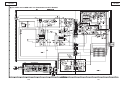
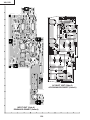
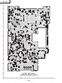
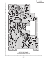
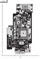
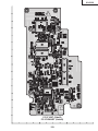
» CHASSIS LAYOUT ........................................ 102
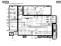
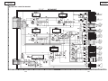
» BLOCK DIAGRAM ......................................... 104
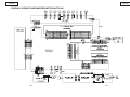
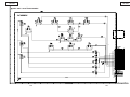
» OVERALL WIRING DIAGRAM ...................... 106
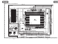
» SCHEMATIC DIAGRAM ................................ 108
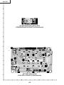
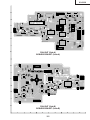
» PRINTED WIRING BOARD ASSEMBLIES ... 152
» PARTS LIST
Ë ELECTRICAL PARTS ................................ 162
Ë CABINET AND MECHANICAL PARTS ..... 178
Ë ACCESSORIES PARTS ............................ 184
Ë PACKING PARTS ...................................... 184
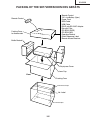
» PACKING OF THE SET ................................. 185
SHARP CORPORATION
Seite
» TECHNISCHE DATEN .................................... 53
» HINWEISE FÜR DAS
WARTUNGSPERSONAL ................................ 54
» BEDIENUNGSANLEITUNG ............................ 56
» AUSBAU WICHTIGER TEILE ......................... 61
» RÜCKSTELLUNG DESLAMPEN-TIMERS ..... 63
» KURZBSCHREIBUNG
DER OPTIK-EINHEIT ...................................... 64
» SOFTWARE-AKTUALISIERUNGSVERFAHREN ................................................... 68
» ELEKTRISCH EINSTELLUNG ........................ 72
» FEHLERSUCHTABELLE ................................. 83
» CHASSIS-ANORDNUNG .............................. 102
» BLOCKSCHALTBILD ..................................... 104
» GESAMTSCHALTPLAN ................................ 106
» SCHEMATISCHEN SCHALTPLANS ............. 108
» LEITERPLATTENEINHEITEN ....................... 152
» ERSATZTEILLISTE
Ë ELEKTRISCHE BAUTEILE ....................... 162
Ë GEHÄUSE UND MECHANISCHE
BAUTEILE ................................................. 178
Ë ZUBEHÖRTEILE ....................................... 184
Ë VERPACKUNGSTEILE ............................. 184
» VERPACKEN DES GERÄTS ......................... 185
This document has been published to be used for
after sales service only.
The contents are subject to change without notice.
XG-C55X
Specifications
Product type LCD Projector
Model XG-C55X
Video system NTSC 3.58/NTSC 4.43/PAL/PAL-M/PAL-N/PAL 60/SECAM/
DTV480I/DTV480P/DTV540P/DTV580I/DTV580P/DTV720P/DTV1035I/DTV1080I
Display method LCD panel × 3, RGB optical shutter method
LCD panel Panel size: 0.99" (25.1 mm) (15 [H] × 20 [W] mm)
No. of dots: 786,432 dots (1,024 [H] × 768 [V])
Standard lens 1—1.27× zoom lens, F1.7—2.2, f = 36.5—46.3 mm
Projection lamp SHP 300 W
Component input signal 15-pin mini D-sub connector
(INPUT1/2) Y: 1.0 Vp-p, sync negative, 75 Ω terminated
PB: 0.7 Vp-p, 75 Ω terminated
PR: 0.7 Vp-p, 75 Ω terminated
Horizontal resolution 750 TV lines (DTV720P)
Computer RGB input signal 15-pin mini D-sub connector
(INPUT 1/2) RGB separate/sync on green type analog input: 0—0.7 Vp-p, positive, 75Ω terminated
HORIZONTAL SYNC. SIGNAL: TTL level (positive/negative)
VERTICAL SYNC. SIGNAL: Same as above
Video input signal RCA connector: VIDEO, composite video, 1.0 Vp-p, sync negative, 75 Ω
(INPUT 3) terminated
S-video input signal 4-pin mini DIN connector
(INPUT 4) Y (luminance signal): 1.0 Vp-p, sync negative, 75 Ω terminated
C (chrominance signal): Burst 0.286 Vp-p, 75 Ω terminated
Computer control signal (RS-232C) 9-pin mini DIN connector
Pixel clock 12—230 MHz
Vertical frequency 43—200 Hz*
Horizontal frequency 15—126 kHz
Audio input signal φ3.5 mm minijack: AUDIO, 0.5 Vrms, more than 47 kΩ (stereo)
Audio output 3.0 W (monaural)
Speaker system 4 cm × 7 cm
Rated voltage AC 100–240V
Input current 4.0 A
Rated frequency 50/60 Hz
Power consumption 400 W (Standard mode)/325 W (Low power mode) with AC 100 V
380 W (Standard mode)/310 W (Low power mode) with AC 240 V
Power consumption (standby) 0.5 W (AC 100 V) – 0.8 W (AC 240 V) (When “Mntr.out/RS232” is set to “OFF”)
Heat dissipation 1,505 BTU/hour (Standard mode)/1,220 BTU/hour (Low power mode) with AC 100 V
1,430 BTU/hour (Standard mode)/1,165 BTU/hour (Low power mode) with AC 240 V
Operating temperature 41°F to 104°F (+5°C to +40°C)
Storage temperature -4 °F to 140°F (-20 °C to +60°C)
Cabinet Plastic
I/R carrier frequency 38 kHz
Dimensions (approx.) 15 3⁄8" × 3 7⁄8" × 11 9⁄16" (390 (W) × 99 (H) × 294 (D) mm) (main body only)
15 1⁄2" × 4 7⁄16" × 11 5⁄8" (393 (W) × 114 (H) × 303 (D) mm) (including adjustment foot
and projecting parts)
Weight (approx.) 11.3 lbs. (5.1 kg)
Supplied accessories Remote control, Two R-6 batteries, Power cord for U.S., Canada etc. (11'10", 3.6 m), Power cord for
Europe, except U.K. (6', 1.8 m), Power cord for U.K., Hong Kong and Singapore (6', 1.8 m), Power
cord for Australia, New Zealand and Oceania (6', 1.8 m), RGB cable (9'10", 3 m), USB cable (3'3",
1 m), DIN-D-sub RS-232C adaptor (5 57⁄64", 15 cm), Remote receiver, Extra air filter, Lens cap (attached), Projector manual and technical reference CD-ROM, Sharp Advanced Presentation Software CD-ROM, Sharp Advanced Presentation Software quick installation guide, Quick guide label,
Operation manual
Replacement parts Lamp unit (Lamp/cage module) (BQC-XGC55X//1), Remote control (RRMCGA176WJSA), Two R-6
batteries (“AA” size, UM/SUM-3, HP-7, or similar), Power cord for U.S., Canada etc.
(QACCDA010WJPZ), Power cord for Europe, except U.K. (QACCVA011WJPZ), Power cord for U.K.,
Hong Kong and Singapore (QACCBA012WJPZ), Power cord for Australia, New Zealand and Oceania
(QACCLA014WJPZ), RGB cable (QCNWGA012WJPZ), USB cable (QCNWG0007CEPZ), DIN-Dsub RS-232C adaptor (QCNWGA015WJPZ), Remote receiver (RUNTKA061WJZZ), Air filter
(PFILDA005WJZZ), Lens cap (PCAPHA003WJSA), Projector manual and technical reference CDROM (UDSKAA035WJZZ), Sharp Advanced Presentation Software CD-ROM (UDSKAA036WJZZ),
Sharp Advanced Presentation Software quick installation guide (TINS-A867WJZZ), Quick guide label (TLABZA364WJZZ), Operation manual (TINS-A812WJZZ)
* Temporary noise may be visible with vertical frequencies above 100Hz if OSD functions are activated.
As a part of policy of continuous improvement, SHARP reserves the right to make design and specification changes for product improvement without prior notice. The performance specification figures
indicated are nominal values of production units. There may be some deviations from these values in
individual units.
2
XG-C55X
IMPORTANT SERVICE SAFETY NOTES (for USA)
Ë Service work should be performed only by qualified service technicians who are
thoroughly familiar with all safety checks and servicing guidelines as follows:
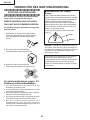
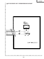
» Use an AC voltmeter with sensitivity of 5000 ohm
per volt., or higher, sensitivity to measure the AC
voltage drop across the resistor (See Diagram).
» All checks must be repeated with the AC plug
connection reversed. (If necessary, a non-polarized
adapter plug must be used only for the purpose of
completing these checks.)
Any reading of 0.3 volts RMS (this corresponds to
0.2 milliamp. AC.) or more is excessive and indicates
a potential shock hazard which must be corrected
before returning the unit to the owner.
WARNING
1. For continued safety, no modification of any circuit
should be attempted.
2. Disconnect AC power before servicing.
BEFORE RETURNING THE PROJECTOR:
(Fire & Shock Hazard)
Before returning the projector to the user, perform
the following safety checks:
1. Inspect lead wires are not pinched between the
chassis and other metal parts of the projector.
2. Inspect all protective devices such as non-metallic
control knobs, insulating materials, cabinet backs,
adjustment and compartment covers or shields,
isolation resistor-capacity networks, mechanical
insulators, etc.
3. To be sure that no shock hazard exists, check for
current leakage in the following manner:
» Plug the AC cord directly into a 120-volt AC outlet,
(Do not use an isolation transformer for this test).
» Using two clip leads, connect a 1.5k ohm, 10 watt
resistor paralleled by a 0.15µF capacitor in parallel
between all exposed metal cabinet parts and earth
ground.
AC
VOLTMETER
1.5k ohm (10W)
0.15 F
TEST PROBE
TO EXPOSED
METAL PARTS
CONNECT TO KNOWN
EARTH GROUND
12345678901234567890123456789012123456789012345678901234567890121234567890123456789012345678901212
12345678901234567890123456789012123456789012345678901234567890121234567890123456789012345678901212
12345678901234567890123456789012123456789012345678901234567890121234567890123456789012345678901212
SAFETY NOTICE
AVIS POUR LA SECURITE
Many electrical and mechanical parts in Projector have
special safety-related characteristics.
These characteristics are often not evident from visual
inspection, nor can protection afforded by them be
necessarily increased by using replacement
components rated for higher voltage, wattage, etc.
Replacement parts which have these special safety
characteristics are identified in this manual; electrical
components having such features are identified by “å”
and shaded areas in the Replacement Parts Lists and
Schematic Diagrams. For continued protection,
replacement parts must be identical to those used in
the original circuit. The use of a substitute replacement
parts which do not have the same safety characteristics
as the factory recommended replacement parts shown
in this service manual, may create shock, fire or other
hazards.
De nombreuses pièces, électriques et mécaniques,
dans les projecteur à présentent des caractéristiques
spéciales relatives à la sécurité, qui ne sont souvent
pas évidentes à vue.
Le degré de protection ne peut pas être nécessairement
augmentée en utilisant des pièces de remplacement
étalonnées pour haute tension, puissance, etc.
Les pièces de remplacement qui présentent ces
caractéristiques sont identifiées dans ce manuel;
les pièces électriques qui présentent ces particularités
sont identifiées par la marque “å” et hachurées dans
la liste des pièces de remplacement et les diagrammes
schématiques. Pour assurer la protection, ces pièces
doivent être identiques à celles utilisées dans le circuit
d’origine. L’utilisation de pièces qui n’ont pas les mêmes
caractéristiques que les pièces recommandées par
l’usine, indiquées dans ce manuel, peut provoquer des
électrocutions, incendies ou autres accidents.
WARNING: The bimetallic component has the primary
conductive side exposed. Be very careful in
handling this component when the power is on.
AVERTISSEMENT: La composante bimétallique dispose du
conducteur primaire dénudé. Faire
attention lors de la manipulation de cette
composante sous tension.
12345678901234567890123456789012123456789012345678901234567890121234567890123456789012345678901212
12345678901234567890123456789012123456789012345678901234567890121234567890123456789012345678901212
12345678901234567890123456789012123456789012345678901234567890121234567890123456789012345678901212
3
XG-C55X
NOTE TO SERVICE
PERSONNEL
12345678901234567890123456789012123456789012345
12345678901234567890123456789012123456789012345
NOTE POUR LE PERSONNEL
D’ENTRETIEN
12345678901234567890123456789012123456789012345
UV-RADIATION PRECAUTION
12345678901234567890123456789012123456789012345
12345678901234567890123456789012123456789012345
PRECAUTION POUR LES RADIATIONS UV
12345678901234567890123456789012123456789012345
12345678901234567890123456789012123456789012345
The light source, metal halide lamp, in the projector
emits small amounts of UV-Radiation.
La source de lumière, la lampe métal halide,
dans le projecteur émet de petites quantités de
radiation UV.
AVOID DIRECT EYE AND SKIN EXPOSURE.
EVITEZ TOUTE EXPOSITION DIRECTE
DES YEUX ET DE LA PEAU.
To ensure safety please adhere to the following:
Pour votre sécurité, nous vous prions de respecter
les points suivants:
1. Be sure to wear sun-glasses when servicing the
projector with the lamp
turned “on” and the top
enclosure removed.
1. Toujours porter des lunettes de soleil lors d’un
entretien du projecteur
avec la lampe allumée
et le haut du coffret retiré.
2. Do not operate the lamp outside of the lamp housing.
2. Ne pas faire fonctionner la lampe à l’extérieur du
boîtier de lampe.
3. Do not operate for more than 2 hours with the
enclosure removed.
3. Ne pas faire fonctionner plus de 2 heures avec le
coffret retiré.
UV-Radiation and High Pressure
Lamp Precautions
Précautions pour les radiations UV
et la lampe haute pression
1. Be sure to disconnect the AC plug when replacing
the lamp.
2. Allow one hour for the unit to cool down before
servicing.
3. Replace only with same type lamp. Type BQCXGC55X//1 rated 80V/300W.
4. The lamp emits small amounts of UV-Radiation,
avoid direct-eye contact.
5. The high pressure lamp involves a risk of explosion.
Be sure to follow installation instructions described
below and handle the lamp with care.
1. To u j o u r s d é b r a n c h e r l a f i c h e A C l o r s d u
remplacement de la lampe.
2. Laisser l’unité refroidir pendant une heure avant de
procéder à l’entretien.
3. Ne remplacer qu’avec une lampe du même type.
Type BQC-XGC55X//1 caractéristique 80V/300W.
4. La lampe émet de petites quantités de radiation UVéviter tout contact direct avec les yeux.
5. La lampe haute pression implique un risque
d’explosion. Toujours suivre les instructions
d’installation décrites ci-dessous et manipuler la
lampe avec soin.
12345678901234567890123456789012123456789012345
4
XG-C55X
12345678901234567890123456789012123456789012345
12345678901234567890123456789012123456789012345
12345678901234567890123456789012123456789012345
12345678901234567890123456789012123456789012345
1234567890123456789012345678901212345678901234
UV-RADIATION PRECAUTION (Continued)
1234567890123456789012345678901212345678901234
1234567890123456789012345678901212345678901234
PRECAUTION POUR LES RADIATIONS UV (Suite)
12345678901234567890123456789012123456789012345
12345678901234567890123456789012123456789012345
12345678901234567890123456789012123456789012345
Lamp Replacement
Remplacement de la lampe
Note:
Remarque:
Since the lamp reaches a very high temperature
during units operation replacement of the lamp
should be done at least one hour after the power
has been turned off. (to allow the lamp to cool off.)
Installing the new lamp, make sure not to touch the
lamp (bulb) replace the lamp by holding its reflector
2.
[Use original replacement only.]
Comme la lampe devient très chaude pendant le
fonctionnement de l’unité, son remplacement ne doit
être effectué au moins une heure après avoir coupé
l’alimentation (pour permettre à la lampe de refroidir).
En installant la nouvelle lampe, s’assurer de ne pas
toucher la lampe (ampoule). Remplacer la lampe en
tenant son réflecteur 2.
[N’utiliser qu’un remplacement d’origine.]
1 Lampe
1 Lamp
2 Reflecteur
2 Reflector
DANGER ! –– Never turn the power on without the
lamp to avoid electric-shock or damage of the
devices since the stabilizer generates high voltages
at its start.
DANGER ! –– Ne jamais mettre sous tension sans
la lampe pour éviter un choc électrique ou des
dommages des appareils car le stabilisateur génère
de hautes tensions à sa mise en route.
Since small amounts of UV-Radiation are emitted
from an opening between the duct cover and the
lamp housing, it is recommended to place the LENS
CAP on the opening during servicing to avoid eye
and skin exposure.
Comme de petites quantités de radiation UV sont
émises par une ouverture entre le couvercle du conduit et le botier de la lampe,il est recommandé de
placer le CAPUCHON D'OPTIQUE sur l'ouverture
pendant l'entretien pour éviter une exposition des
yeux et la peau.
5
XG-C55X
WARNING:
High brightness light source, do not stare into the beam of light, or view directly. Be especially
careful that children do not stare directly in to the beam of light.
WARNING:
TO REDUCE THE RISK OF FIRE OR ELECTRIC SHOCK, DO NOT EXPOSE THIS UNIT TO
MOISTURE OR WET LOCATIONS.
CAUTION
The lighting flash with arrowhead within
a triangle is intended to tell the user that
parts inside the product are risk of electric
shock to persons.
RISK OF ELECTRIC SHOCK.
DO NOT REMOVE SCREWS
EXCEPT SPECIFIED USER
SERVICE SCREW
CAUTION: TO REDUCE THE RISK OF ELECTRIC SHOCK,
DO NOT REMOVE CABINET.
NO USER-SERVICEABLE PARTS EXCEPT LAMP UNIT.
REFER SERVICING TO QUALIFIED SERVICE
PERSONNEL.
The exclamation point within a triangle is
intended to tell the user that important
operating and servicing instructions are
in the manual with the projector.
12345678901234567890123456789012123456789012345678901234567890121234567890123456789012345678901212
12345678901234567890123456789012123456789012345678901234567890121234567890123456789012345678901212
AVERTISSEMENT: Source lumineuse de grande intensité. Ne pas fixer le faisceau lumineux ou le regarder
directement. Veiller particulièrement à éviter que les enfants ne fixent directement le
faisceau lumineux.
AVERTISSEMENT: AFIN D’EVITER TOUT RISQUE D’INCENDIE OU D’ELECTROCUTION, NE PAS PLACER
CET APPAREIL DANS UN ENDROIT HUMIDE OU MOUILLE.
ATTENTION
L’éclair terminé d’une flèche à l’intérieur
d’un triangle indique à l’utilisateur que les
pi‘eces se trouvant dans l’appareil sont
susceptibles de provoquer une décharge
électrique.
RISQUE
D’ELECTROCUTION NE
PASRETIRER LES VIS, A
L’EXCEPTION DES VIS DE
REPARATION UTILISATEUR
SPECIFIEES
Le point d’exclamation à l’intérieur d’un
triangle indique à l’utilisateur que les
instructions de fonctionnement et
d’entretien sont détaillées dans les
documents fournis avec le projecteur.
ATTENTION: POUR EVITER TOUT RISQUE
D’ELECTROCUTION, NE PAS RETIRER LE CAPOT.
AUCUNE DES PIECES INTERIEURES N’EST REPARABLE
PAR L’UTILISATEUR, A L’EXCEPTION DE L’UNITE DE
LAMPE. POUR TOUTE REPARATION, S’ADRESSER A UN
TECHNICIEN D’ENTRETIEN QUALIFIE.
6
XG-C55X
Precautions for using lead-free solder
1 Employing lead-free solder
"Input, Output, R/C Receiver, Fan PWB, AC INLET UNIT, POWER UNIT and Key PWB" of this model employs leadfree solder. The LF symbol indicates lead-free solder, and is attached on the PWBs and service manuals. The
alphabetical character following LF shows the type of lead-free solder.
Example:
LFa
Indicates lead-free solder of tin, silver and copper.
2 Using lead-free wire solder
When fixing the PWB soldered with the lead-free solder, apply lead-free wire solder. Repairing with conventional
lead wire solder may cause damage or accident due to cracks.
As the melting point of lead-free solder (Sn-Ag-Cu) is higher than the lead wire solder by 40°C, we recommend you
to use a dedicated soldering bit, if you are not familiar with how to obtain lead-free wire solder or soldening bit,
contact our service station or service ranch in your area.
3 Soldering
As the melting point of lead-free solder (Sn-Ag-Cu) is about 220°C which is higher than the conventional lead solder
by 40°C, and as it has poor solder wettabillty, you may be apt to keep the soldering bit in contact with the PWB for
extended period of time. However, Since the land may be peeled off or the maximum heat-resistance temperature of
parts may be excoeded, remove the bit from the PWB as soon as you conurm the steady soldering condition.
Lead-free solder contains more tin, and the end of the soldering bit may be easily corroded. Make sure to tum on and
off the power of the bit as required.
if a different type of solder stays on the tip of the soldering bit, it is alloyed with lead-free solder. Clean the bit after
every use of it.
When the tip of the soldering bit is blackened during use, file it with steel wool or fine sandpaper.
Becareful when replacing parts with polarity indication on the PWB silk.
Lead-free wire solder for servicing
Part No.
ZHNDAi123250E
ZHNDAi126500E
ZHNDAi12801KE
★
J
J
J
Description
φ0.3mm
250g(1roll)
φ0.6mm
500g(1roll)
φ1.0mm
1kg(1roll)
7
Code
BL
BK
BM
XG-C55X
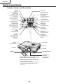
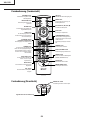
OPERATION MANUAL
Pr oj ector (Front and Top Vi ew )
ON button
INPUT button
For turning the power on.
For switching input mode
1, 2, 3 or 4.
Power indicator
Illuminates red, when the
projector is in standby.
When the power is turned
on, this indicator will
illuminate green.
KEYSTONE button
For adjusting Keystone or
Digital Shift setting.
AUTO SYNC button
STANDBY button
For automatically
adjusting images when
connected to a computer.
For putting the projector into
the standby mode.
Lamp indicator
STANDBY
Adjustment buttons
(', ", \, |)
Illuminates green indicating
normal function. Replace
the lamp when the indicator
illuminates red.
For selecting menu items.
VOLUME buttons
For adjusting the speaker
sound level.
Temperature warning
indicator
When the internal
temperature rises, this
indicator will illuminate red.
MENU button
For displaying adjustment
and setting screens.
UNDO button
For undoing an operation
or returning to the default
settings.
ENTER button
For setting items selected
or adjusted on the menu.
HEIGHT ADJUST
button
Zoom knob
Focus ring
Adjustment foot
Intake vent
Carrying handle
Remote control
sensor
Attaching and removing the lens cap
• Press on the two buttons of the lens cap
and attach it on the lens. Then release
the buttons to lock it in place.
• Press on the two buttons of the lens cap
and remove it from the lens.
8
Air filter/cooling
fan (Intake vent)
(on the bottom of
the projector)
XG-C55X
9
XG-C55X
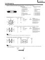
Remote Control (F ront Vi ew )
STANDBY button
ON button
For putting the projector into the
standby mode.
For turning the power on.
MENU button
KEYSTONE button
For displaying adjustment and
setting screens.
For adjusting Keystone or Digital
Shift setting.
Adjustment buttons
(', ", \, |)
ENTER button
For setting items selected or
adjusted on the menu.
For selecting menu items.
PinP button
UNDO button
For displaying dual pictures.
For undoing an operation or
returning to the default settings.
FORWARD/BACK buttons
ENLARGE (Enlarge/Reduce)
buttons
Same function as the [Page Down]
and [Page Up] keys on a computer
keyboard when using the Remote
receiver.
For enlarging or reducing part of
the image.
GAMMA button
FREEZE button
For correcting the brightness of an
image, when the images displayed
are hard to see because of the
brightness of the room. Four
gamma modes are available to
choose from.
For freezing images.
BLACK SCREEN button
For superimposing a black screen.
RESIZE button
AUTO SYNC button
For switching the screen size
(NORMAL, BORDER, etc).
For automatically adjusting images
when connected to a computer.
MUTE button
INPUT buttons
For temporarily turning off the
sound.
For switching to the respective
input modes.
VOLUME buttons
BREAK TIMER button
For adjusting the speaker sound
level.
For displaying the break timer.
Remote Control (Top View )
WIRED R/C JACK
For controlling the projector by
connecting the remote control to the
projector.
Remote control signal transmitters
10
XG-C55X
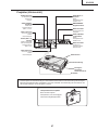
Connection Pin Assignments
INPUT 1/2 RGB and OUTPUT Signal Terminal: 15-pin Mini D-sub female connector
RGB Input
5
10
15
1
6
11
1.
2.
3.
4.
5.
6.
7.
8.
9.
10.
11.
12.
13.
14.
15.
Component Input
Video input (red)
Video input (green/sync on green)
Video input (blue)
Not connected
Not connected
Earth (red)
Earth (green/sync on green)
Earth (blue)
Not connected
GND
Not connected
Bi-directional data
Horizontal sync signal : TTL level
Vertical sync signal : TTL level
Data clock
1.
2.
3.
4.
5.
6.
7.
8.
9.
10.
11.
12.
13.
14.
15.
PR (CR)
Y
PB (CB)
Not connected
Not connected
Earth (PR)
Earth (Y)
Earth (PB)
Not connected
Not connected
Not connected
Not connected
Not connected
Not connected
Not connected
RS-232C Terminal: 9-pin Mini DIN female connector
8
9
7
6
3
Pin No.
1
2
3
4
5
6
7
8
9
Signal
Name
RD
SD
Receive Data
Send Data
SG
Signal Ground
I/O
Output
Input
Output
Input
Input
Output
Input
Output
RS
CS
Reference
Not connected
Connected to internal circuit
Connected to internal circuit
Not connected
Connected to internal circuit
Not connected
Connected to Pin 8
Connected to Pin 7
Not connected
4
5
2
1
6
1
5
9
9-pin D-sub male connector of the DIN-D-sub RS-232C adaptor
Pin No.
1
2
3
4
5
6
7
8
9
Signal
CD
RD
SD
ER
SG
Name
I/O
Receive Data
Send Data
Input
Output
Signal Ground
RS
CS
CI
Reference
Not connected
Connected to internal circuit
Connected to internal circuit
Not connected
Connected to internal circuit
Not connected
Connected to internal circuit
Connected to internal circuit
Not connected
Note
Pin 8(CS) and Pin 7(RS) are short circuited inside the projector.
RS-232C Cable recommended connection: 9-pin D-sub female connector
5
9
1
6
Pin No.
1
2
3
4
5
6
7
8
9
Signal
CD
RD
SD
ER
SG
DR
RS
CS
CI
Pin No.
1
2
3
4
5
6
7
8
9
Signal
CD
RD
SD
ER
SG
DR
RS
CS
CI
Note
Depending on the controlling device used, it may be necessary to connect Pin 4 and Pin 6 on the controlling
device (e.g. PC).
Projector
Pin No.
4
5
6
PC
Pin No.
4
5
6
11
XG-C55X
Dimensions
12
XG-C55X
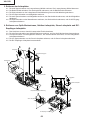
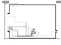
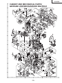
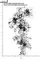
REMOVING OF MAJOR PARTS
1. Removal of the bottom filter cover and lamp unit cover
1-1.
1-2.
1-3.
1-4.
Detach the bottom filter cover.
Loosen the lock screw from the lamp unit cover, and detach the lamp unit cover.
Pull out the carrying handle.
Press the ~-marked spot of the upper half of the lens cover to unhook the claw, and detach the upper lens
cover.
1-5. Detach the lower half of the lens cover.
2. Removal of the top panel and rear panel
2-1. Remove the six lock screws (black) from the top panel.
2-2. Remove the eight lock screws from the rear panel and detach the rear panel.
( 2-2 :XEBSF30P12000, 2-2 :XBBSF30P10000)
2-3. Slowly lift the top panel and disconnect the connector from the key PWB. Remove another screw and detach
the top panel.
Lamp unit cover
1-2
1-4
Upper half of the lens cover
1-3
1-1
Carrying handle
1-5
Lower half of the lens cover
Top panel
Bottom filter cover
2-2
2-2
2-3
Rear panel
2-1
(Black)
13
XG-C55X
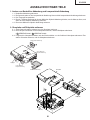
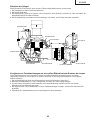
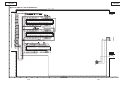
3. Removal of the PWBs
3-1.
3-2.
3-3.
3-4.
3-5.
3-6.
Remove the lock screw from the lamp socket angle. Detach the lamp socket angle.
Lift the ballast unit. Disconnect the two connectors and detach the ballast unit.
Remove the lock screw from the PWB unit cover and detach the cover.
Remove the three lock screws from the PWB assembly.
Remove the two lock screws from the cooling fan, disconnect the connector and detach the cooling fan.
Remove the lock screw from the grounding terminal, disconnect the connector and detach the AC inlet PWB.
4. Removal of the optical mechanism, fan PWB, power PWB and R/C receiver PWB
4-1.
4-2.
4-3.
4-4.
4-5.
Disconnect the connector and detach the speaker unit.
Remove the eight lock screws from the optical mechanism, and take out the optical mechanism.
Remove the lock screw from the cooling fan, and detach the cooling fan and fan PWB.
Remove the four lock screws from the power PWB, and detach the power PWB.
Take out the R/C receiver PWB.
3-5
3-4
3-4
Cooling Fan
PWB Ass’y
3-1
3-5
Ballast Unit
3-6
3-2
AC Inlet PWB
4-3
4-2
Cooling Fan
3-3
Fan PWB
4-2
PWB Unit cover
4-4
Power PWB
4-1
R/C Receiver PWB
14
4-2
XG-C55X
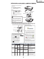
RESETING THE TOTAL LAMP TIMER
1
Connect the power cord.
• Plug the power cord into the AC socket
of the projector.
2
Reset the lamp timer.
• While pressing simultaneously
and
on the projector, press
the projector.
,
ON
AC socket
on
• "LAMP 100%" is displayed, indicating
that the lamp timer is reset.
INPUT button
ENTER button
Power (ON)
button
UNDO buttom
Info
• Make sure to reset the lamp timer only
when replacing the lamp. If you reset the
lamp timer and continue to use the same
lamp, this may cause the lamp to become
damaged or explode.
Ë The warning lights on the projector indicate problems inside the projector.
Ë If a problem occurs, either the temperature warning indicator or the lamp replacement indicator will
illuminate red, and the power will turn off. After the power has been turned off, follow the procedures given below.
About the lamp
replacement indicator
Power indicator
Lamp replacement
indicator
Temperature warning
indicator
About the temperature warning indicator
If the temperature inside the projector increases, due to blockage
of the air vents, or the setting lo" will blink in the
cation, "
lower left corner of the picture. If
the temperature keeps on rising,
the lamp will turn off and the temperature warning indicator will
blink, the cooling fan will run for
further 90 seconds, then the power
" apwill be shut off. After "
pears, be sure to perform the following measures.
Maintenance indicator
Abnormal
Normal
Temperature
warning
indicator
Lamp
replacement
indicator
Power
indicator
Off
Green on
Green
blinks
when the
lamp is
active.
Green on/
Red on
Red on/
Power off
Red blinks/
Red on
Red on/
Power off
Red blinks
Condition
ËThe lamp life becomes 0%, when used
for approximately 3,000 hours with "ON"
in "Power Save" or when used for approximately 2,000 hours with "OFF" in "Power
Save".
ËWhen the remaining lamp life becomes
6% or less, " " will be displayed on the
screen in yellow. When the percentage
becomes 0%, " " will change to " "
(red), the lamp will automatically turn off
and then the projector as well. At this time,
the lamp replacement indicator will illuminate in red.
ËIf you try to turn on the projector a fourth
time without replacing the lamp, the projector will not turn on.
Problem
Blocked air intake
Possible Solution
• Relocate the projector to an area
with proper ventilation.
The internal
• Cooling fan breaktemperature is
• Take the projector to your nearest
down
abnormally high.
• Internal circuit failure Sharp Authorized Projector Dealer
or Service Center for repair.
• Clogged air intake
• Remaining lamp life
Time to change
becomes 6% or
• Carefully replace the lamp.
the lamp
under.
• Take the projector to your nearest
Sharp Authorized Projector Dealer
or Service Center for repair.
• Please exercise care when
The lamp does
• Burnt-out lamp
• Lamp circuit failure
not illuminate.
replacing the lamp.
The power
indicator blinks
in red when the
projector is on.
• The filter cover, lamp
unit cover or lens
cover is open.
15
• Securely install the filter cover.
• If the power indicator blinks even
when the filter cover is securely
installed, contact your nearest
Sharp Authorized Projector Dealer
or Service Center for advice.
XG-C55X
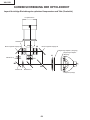
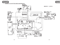
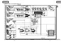
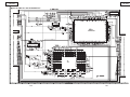
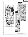
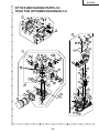
THE OPTICAL UNIT OUTLINE
Layout for proper setup of the optical components and parts (top view)
Projection Lens
Relay lens3
L2
M5 AL-coated mirror B
M4 AL-coated mirror R
Fly-eye lens (Output)
Fly-eye lens (Input)
L1
Relay lens 2
L2
M3
G reflector
R reflector
M2
B reflector
Relay lens 1
Light source (Lamp)
16
XG-C55X
Adjusting the mirrors
This adjustment is needed when any of the optical parts of the optical mechanism has been replaced.
1. Disconnect the flat cables from all the LCD panels.
2. Light up the lamp.
3. Project a white-light image and check to see if there is any color tint in any direction. If any, use the M2, M4 and M5
adjusting levers.
4. Loosen the adjusting lever lock screws, make adjustments, and tighten up the lock screws.
M5 Adjusting lever
M4 Adjusting lever
Lock screws
Screw A
Lock screws
Lock screws
M2 Adjusting lever
Lever D
Screw B
Correcting color irregularities on white-only screen when replacing the lamp
If color irregularities are found at the right and left on a white-only screen after replacing the lamp, it is necessary to
readjust the optical axis of the new lamp. Take the following steps.
1. Open the lamp cover and loosen the screws A and B at the top of the lamp.
2. Using a screwdriver or the like, move the lever D in the arrow direction.
3. Temporarily fix the screws A and B, close the lamp cover, and check the white-only screen again for color
irregularities.
4. Repeat the above steps 1 and 2 until there will be no color irregularities. Now tighten up the screws A and B.
5. Finally secure the lamp cover back in position.
17
XG-C55X
Replacing the prism unit
1. Remove the four lock screws, and take the prism holder unit out of the optical unit.
2. Replace the prism unit with new one. Take the above step 1 in reverse order.
Note: Even if just one of the LCD panels is defective, it is necessary to replace the entire prism unit. Do not replace
just the defective LCD panel only. Under the present circumstances, please do not touch the display part of
LCD.
G-LCD panel
R-LCD panel
Prism unit lock screws
B-LCD panel
Optical unit
18
XG-C55X
How to Release the System Lock
Turn on the power. If the system lock is applied, the system-resetting screen appears. Press the following keys in this
order.
MENU → ENTER → ENTER → MENU → UNDO → UNDO → MENU
After pressing the MENU key first, press the remaining six keys within 10 seconds.
19
XG-C55X
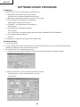
SOFTWARE UPDATE PROCEDURE
Preparation
1. Install the Tera Term Pro (communication program) into PC.
1.1 Downloaded the Tera Term Pro from the Internet.
http://hp.vector.co.jp/authors/VA002416/teraterm.html
1.2 Decompress ttremp23.zip and then run setup.exe in the folder.
1.3 The Language list box appears in the dialog box.
Select English and then click Continue.
1.4 The NOTE: ~ message appears in the dialog box.
Click Continue.
1.5 The Destination Path dialog box appears.
Click Continue.
It is not necessary to change the default destination path(c:\PROGRAM FILES\TTERMPRO).
1.6 The Complete dialog box appears.
Click OK.
2. Decompress the software file for update to the suitable folder.
Loading software
1. Turn on the projector.
2. Connect the RS-232C-IN port of the projector and the RS-232C port of your PC with a DIN-D-sub RS-232C
adapter and a RS-232C serial control cable (cross type).
3. Run the Tera Term Pro (communication program).
3.1 The New connection dialog box appears, select the Serial and then select the suitable COM port.
Then click OK.
3.2 On the Tera Term Pro, select the Setup and then the Terminal.
Change Receive to CR+LF and then check Local echo.
Then click OK.
20
XG-C55X
3.3 Make sure that ERR is returned from the projector when you pressed the ENTER key.
4. Call the process mode.
Press the following keys in this order.
POWER ON / Adj up / Adj down / Adj up / Adj down / ENTER / ENTER / MENU
5. Select the SPECIAL on the process menu and then press the ENTER key.
6. Select the IPL2 on the sub menu and then press the ENTER key.
The lamp turns off and the projector goes into the software write mode.
7. Once unplug the AC cord and then plug it in again.
Note: Be sure to unplug the AC cord once and plug it in again.
8. On the Tera Term Pro, enter the RATE1152 and then press the ENTER key.
9. On the Tera Term Pro, select the Setup and then the Terminal.
Uncheck the Local echo and then click the OK button.
21
XG-C55X
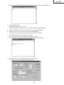
10. On the Tera Term Pro, select the Setup and then the Serial port.
Change the Baud rate to 115200 and then click the OK button.
11. On the Tera Term Pro, enter the START and then press the ENTER key.
Make sure that the OK is returned from the projector and the lamp indicator is blinking in green.
12. On the Tera Term Pro, select the File and then the Send file.
Check the Binary in the Option and then select the software file for update you decompressed.
Then click open.
22
XG-C55X
13. The transfer of data starts if the setting is correct. The Bytes transferred will be counted in the dialog box.
14. Wait for several minutes until the OK is displayed two times and then the lamp indicator is illuminated in red.
If the ERR is displayed, take the steps again from the step 1.
15.
16.
17.
18.
Caution: Never turn off the projector or unplug the AC cord while transferring the data. If it is done, the projector
becomes unable to turn the power on.
In case of this, recover the projector by taking the following steps.
(1) Remove the top and the back side cabinet of the projector.
(2) Set the switch on the PC board to the WRITE side.
(3) Plug the AC cord.
(4) Take the steps again from the step 8.
(5) After transferring the data, set the switch on the PC board to the NORMAL side.
Unplug the AC cord.
Plug in the AC cord and then call the process mode.
From the process menu, select the SPECIAL.
Make sure that the PRG VER is changed to new version.
Turn off the projector.
The update is complete.
23
XG-C55X
ELECTRICAL ADJUSTMENT
No.
Adjustment Items
Adjustment Conditions
Adjustment Procedures
1
Initialization of
EEPROM
1. Turn on the power (the lamp lights
up) and warm up the system for 15
minutes.
1. Make the following settings.
Press S2601 to enter the process
mode, and execute S2 on the SSS
menu. Now the EEPROM, except for
the PC I/F unit, is initialized.
Do not execute S1, or the PC I/F unit
itself will be initialized.
(The PC I/F unit has been factoryadjusted.)
To adjust the PC I/F unit, refer to "How
to Adjust the PC I/F unit" on the
page30.
2
Adjustment of
RGB1 black level
signal amplitude
1. Select the following group and subjects.
Group: OUTPUT1
Subject: G1-BLK, G1-GAIN
For the color R, select the subjects
R1-BLK and R1-GAIN.
For the color B, select the subjects
B1-BLK and B1-GAIN.
2. Make sure the process adjustment
color bars are displayed.
3. For the color G, connect a oscilloscope to pin (2) of P1301.
4. For the colors R and B, connect the
oscilloscope to pin (1) of P1301 and
pin (3) of P1301, respectively.
1. Select the subject G1-GAIN. Using
the set's control switch or the remote
controller button, adjust the setting
so that the signal amplitude is 4.2
Vp-p±0.05 V.
2. Select the subject G1-BLK. Using the
set's control switch or the remote
controller button, adjust the setting
so that the white-to-white level is 1.4
Vp-p±0.1 V.
3. Do the same for the other colors R
and B.
1. Select the following group and subjects.
Group: OUTPUT2
Subject: PSIG-H, PSIG-L
Make sure the PSIG-H and PSIGL settings are 145 and 170, respectively.
1. Get the PSIG waveform displayed.
(Feed the XGA signal.)
3
Adjustment of
PSIG
1.4Vp-p
4.2Vp-p
PSIG
2.9V DC
6.0V DC
GND
Adjust the PSIG-H setting. Adjust the PSIG-L setting.
4
Checking of
sample-and-hold
pulse phase
1. Feed the XGA-mode 75-Hz black
signal.
2. Select the following group and subject.
Group: OUTPUT3
Subject: ENBXR-PH
ENBXG-PH
ENBXB-PH
24
1. Check the blurring of the letters of
OUTPUT 3 and the ghost.
2. Raise the value of the ENBXR-PH
until the front ghost appears on the
left side of the letters of OSD.
3. When the value is lowered for 1 - 2
points, the front ghost disappears.
Set it to the value for 1 lowered from
the value when the front ghost
disappears.(In case that the front
ghost appears when the value of the
EMBXR-PH is 11 and disappears
when it is 10, set it to 9.)
4. Adjust the green and blue in the same
manner.
XG-C55X
No.
Adjustment Items
Adjustment Conditions
Adjustment Procedures
5
Adjustment of
RGB countervoltage
1. Feed the counter-voltage adjustment signal (XGA) prepared by the
Technical Department.
2. Select the following group and subjects.
Group: OUTPUT3
Subject: RC (R), GC (G), BC (B)
1. Using the set's control switch or the
remote controller button, adjust the
settings to minimize flickers.
2. If the results are inconsistent at the
center and on both sides onscreen,
readjust the settings to get the same
results on both sides.
6
Adjustment of
RGB gradation
reproduction
1. Feed the SMPTE pattern signal
(XGA) .
2. Select the following group and subject.
Group: OUTPUT1
Subject: G1-BLK
1. Confirm that the 100% and 95% white
gradation as well as the 0% and 5%
black gradation are discernible.
2. If the white gradation looks differently,
finely adjust the G1-BLK setting.
7
Adjustment of
RGB white balance
1. Feed the 32-step gray scale signal
(XGA, 60 Hz).
2. Select the following group and subjects.
Group: OUTPUT1
Subjects: R1-BLK (R), B1-BLK (B)
1. Adjust the R1-BLK and B1-BLK settings to have the specified gradation
balance (according to the standard
monitor).
8
Adjustment of
video AGC
1. Feed the NTSC 10-step gray scale
signal.
2. Select the following group and subject.
Group: VIDEO
Subject: AGC-ADJ
3. Connect the oscilloscope between
TP4501 and TP4502
1. Using the set's control switch or the
remote controller button, adjust the
setting so that the white-to-black level
is 0.72 Vp-p±0.01 V.
9
Adjustment of
video brightness/
contrast
1. Feed the NTSC100% window pattern signal.
2. Select the following group and subjects.
Group: VIDEO
Subject: AUTO, PICTURE/BRIGHT
1. Feed the signal. Using the set's control switch or the remote controller
button, select the subject AUTO. The
setting will adjust itself.
2. And then lower the adjustment value
of the PICTURE/BRIGHT by 2 points.
3. Then adjust the PICTURE/BRIGHT
setting until the signal becomes bitless.
10
Adjustment of
video tint
1. Feed the split color bar signal.
2. Select the following group and subject.
Group: VIDEO1
Subject: TINT
1. Confirm the fixed value.
Fixed value: 128
25
XG-C55X
No.
11
Adjustment Items
Adjustment of
NTSC color
saturation
Adjustment Conditions
Adjustment Procedures
1. Feed the split color bar signal.
2. Select the following group and subject.
Group: VIDEO
Subject: N-COLOR
~ Connect the oscilloscope to pin (1)
of P1301.
1. Confirm the fixed value.
Fixed value: 54
(Reference: 0.4 Vp-p)
12
Adjustment of PAL 1. Feed the PAL color bar signal.
color saturation
2. Select the following group and subject.
Group: VIDEO
Subject: P-COLOR
~ Connect the oscilloscope to pin (1)
of P1301.
1. Confirm the fixed value.
Fixed value: 51
(Reference: 0.4 Vp-p)
100% White Red
13
Adjustment of
SECAM color
saturation
1. Feed the SECAM color bar signal.
2. Select the following group and subject.
Group: VIDEO
Subject: S-COLOR
~ Connect the oscilloscope to pin (1)
of P1301.
1. Confirm the fixed value.
Fixed value: 48
(Reference: 0.5 Vp-p)
100% White Red
100% White Red
14
Adjustment of
video white balance
1. Feed the NTSC monoscope pattern
signal.
2. Select the following group and subjects.
Group: VIDEO
Subjects: V-R1-BLK, V-B1-BLK
1. Using the set's control switch or the
remote controller button, adjust the
settings to have the same white balance as on the standard monitor.
15
Adjustment of
COMPO CB offset
and CR offset
1. Feed the Y-0% brightness, Cb and
Cr 0% white pattern color difference
signal (480I).
2. Select the following group and subject.
Group: COMPO
Subject: AUTO
1. Feed the signal. Using the set's control switch or the remote controller
button, select the subject AUTO. The
setting will adjust itself.
16
Adjustment of
COMPO brightness
1. Feed the 0% gray pattern signal
(480I).
2. Select the following group and subject.
Group: COMPO
Subject: G-BRIGHT
1. Adjust so that pixel defect occurs on
the screen.
26
XG-C55X
No.
Adjustment Items
Adjustment Conditions
Adjustment Procedures
17
Adjustment of
COMPO white
balance
1. Feed the DTV monoscope pattern
signal.
2. Select the following group and subjects.
Group: COMPO
Subjects: C-R1-BLK, C-B1-BLK
1. Using the set's control switch or the
remote controller button, adjust the
settings to have the same white balance as on the standard monitor.
18
Automatic color
1. Apply the automatic color correcirregularity correction using the automatic color irregution
larity correction system (ccdc).
1. Make sure that no remarkable uneven
color remains on the screen.
19
Checking of
tracking
1. Input the RGB 10-step gray-scale
(inverse vertically) signal.
2. Select the following group and subject.
Group: LINE
Subject: OPT-MECH
Check the tracking of the gradation on
the lower side.
In case that it is bad, adjust the OPTMECH value to the optimum.
(It takes 2 - 3 seconds for changing for
selection.)
0:Red and blue up
1:Red and blue down
2:Initial value (Normal)
20
Adjustment of
sRGB white
balance
1. Feed the RGB 50% gray pattern
signal.
2. Select the following group and subjects.
Group: OUTPUT1
Subjects: S-R1-BLK, S-R1-GAIN, SG1-BLK, S-G1-GAIN, S-B1-BLK, SB1-GAIN
3. Have the BM-5 brightness meter and
the standard white board at hand.
1. Make the S-R1-GAIN setting the
same as the R1-GAIN one.
Make the S-G1-GAIN setting the
same as the R1-GAIN one.
Make the S-B1-GAIN setting the
same as the R1-GAIN one.
Make the S-R1-BLK setting the same
as the R1-BLK one.
2. Adjust the S-B1-BLK and S-G1-BLK
settings so that the chromaticity on
the brightness meter should be as
follows.
x: .313±7/1000
y: .350±10/1000
Cautions on 3D irregular color correction adjustment
The following measurement and adjustment must be carried out:
• In a dark room (take care for stray light)
• Using diffuse reflection type (mat type) screen in the uniform conditions.
Settings of the projector must be carried out in the following conditions:
• Do not save power (to keep the lamp to the stable condition during measurement)
• Automatic search cancel (to fix INPUT1)
• INPUT1 RGB mode (cancel the component mode of INPUT 1, just in case)
(1) System setting (“setting” - “system setting”)
System optional
Simultaneous write in of 3D correction value:
Char transmission interval:
Binary interval:
No (not checked)
0 ms
2 ms
27
XG-C55X
Creation of correction value by straight-line
correction coefficient:
Number of image captures (when adjustment,
measurement):
Number of image captures (when teaching):
No (not checked)
2 times
4 times
(2) Teaching
Basically only one time measurement is necessary for each model for teaching, however when the optical
characteristics, etc. of the set are greatly changed, set the conditions again and measurement is necessary again according to the changes.
Measurement method of the correction coefficient
(1) Determines the standard set of C55. 1 unit (n units)
(2) Set settings are RGB mode INPUT 1.
(3) Execute teaching in the following condition setting in that standard set.
Condition setting
Model name:
Newly input the model name and optical characteristics Var.
Resolution:
(Not related)
Correction value X direction:
29
Correction value Y direction:
22
Correction bits number:
8
Minimum adjustment value:
0
Center adjustment value:
36
Maximum adjustment value:
73
Teaching number:
5
Teaching interval:
18
Brightness change direction by adjustment value: Brightness up with adjustment value + (checked)
Adjusting points:
3-dimension (checked)
Gradation 4 (checked)
Gradation 5 (checked)
Gradation 6 (checked)
Do not check the gradations other than these.
Adjusting point (Test pattern display level)
Gradation 7:
91%
Gradation 6:
78%
Gradation 5:
65%
Gradation 4:
52%
Gradation 3:
40%
Gradation 2:
25%
Gradation 1:
13%
Gradation 0:
0%
Adjustment color:
Adjustment with WHITE (checked)
(3) Color irregularity correction
Conditions setup
Correction procedure settings
Gradation 7:
2. Lower-gradation correction value to be used.
Gradation 6:
0. Correction with correction coefficient.
Gradation 5:
0. Correction with correction coefficient.
Gradation 4:
0. Correction with correction coefficient.
Gradation 3:
1. Upper-gradation correction value to be used.
28
XG-C55X
Gradation 2:
1. Upper-gradation correction value to be used.
Gradation 1:
1. Upper-gradation correction value to be used.
Gradation 0:
1. Upper-gradation correction value to be used.
For the model in question, select the name entered in (2) to start the color irregularity correction. If the
set has its optical characteristics rather different from the standard ones or if the set has some color
irregularity lines missing, do the teaching for that set in particular. Use its specified correction coefficients in making the adjustment.
No.
Adjustment Items
Adjustment Conditions
Adjustment Procedures
21
Checking and
readjustment of
white balance
1. The adjusting conditions for each
item are as follows:
For RGB input, see Item 7.
For video input, see Item 14.
For COMPO input, see Item 17.
1. Make sure the white balance is as
specified on the standard monitor.
For readjustment, proceed in the order of RGB input, video input and
COMPO input.
22
Checking colorrelated performance
1. Receive the color bar signal.
1. Select L1 in the process mode.
Check the performance of Color and
Tint.
23
Checking of
picture-related
performance
1. Receive the monoscope pattern signal.
1. Select L2 in the process mode.
Check Picture, Brightness and Sharpness.
24
Checking of RGB
performance
1. Receive the RGB signal.
1. Select L4 on the process mode.
Check Picture, Brightness, Red, Blue,
Clock, Phase, H-POS and V-POS.
25
Checking of offtimer performance
26
Checking of
thermistor performance
1. Heat the thermistor with a hair dryer.
1. Make sure the temperature is displayed.
27
Automatic sync
operation
1. Receive the phase checking pattern
signal.
1. Make sure that Clock, Phase, H-POS
and V-POS can be automatically
adjusted in the VGA/S-VGA/XGA
mode.
28
Vertical line level
check
1. Receive the RGB signal. 10-step
gray-scale
1. Compare with the vertical line boundary sample, and it must be at the
boundary sample or less. In case that
it is bad, adjust the PSIG-L of the
item 3.
However, it must be within the range
of 190 - 200.
29
Factory settings
1. Select OFF in the process mode.
Make sure that the off-timer starts
with 5-minute display, counts down
1 minute for 1 second, and turns off
when 0 minute is displayed.
1. Make the following settings.
Destination
29
Remote
Process
controller
adjustment settings
NorthAmerican
S4
Factory
Setting 4
Other
S3
Factory
Setting 3
XG-C55X
How to Adjust the PC I/F unit
1. Initialization of EEPROM
1) Press SW2601 to enter the process mode.
2) Execute S1 on the SSS menu. (By S1, the PC board alone is initialized. Do not execute S2, or all the
adjustment data, except for the PC I/F unit, is initialized.)
3) Make sure that the program version "VER. XXX" on the SPECIAL menu is the latest one.
2. Level adjustments
2-1. Setting the oscilloscope
Set the oscilloscope's range to DC1V/div and 5µ S/div.
2-2. Connecting the PC interface
1) Connect the specified cable between ANALOG OUTPUT (on the signal generator) and DSUB connector
(INPUT1 on the projector).
2) Set the projector's input selector to INPUT1.
3) Set the signal generator to XGA mode (1024x768, 60Hz, 32-step gradation). Also adjust the output
amplitude (between black and white) to 700 mVp-p (terminated with a 75-ohm impedance).
4) Turn on the power.
2-3. Adjusting items
1) Adjustment of RGB drive/gain
(1) Feed the window pattern signal that has 100% and 0% signals.
(2) Select AUTO among the A/D items in the process mode and make the adjustments.
30
XG-C55X
» Entering the adjustment process mode
There are following two methods.
» Press the SW2601 on the Output unit.
» Press the follwing keys in this order.
ON→Adj up→Adj down→Adj up→Adj down→ENTER→ENTER→MENU
» Adjustment mode process menu
Group
Adjust PC Image
A/D
Sub Group
Adjust RGB Image
OUTPUT1
Adjust Panel Drive
OUTPUT2
Adjust Commn Voltage
OUTPUT3
31
Subject
R-BRIGHT
G-BRIGHT
B-BRIGHT
R-D
B-D
G-D
AD-AUTO
R1-BLK
R1-GAIN
G1-BLK
G1-GAIN
B1-BLK
B1-GAIN
S-R1-BLK
S-R1-GAIN
S-G1-BLK
S-G1-GAIN
S-B1-BLK
S-B1-GAIN
PSIG-H
PSIG-L
LC-SW
LC-R-SIG
LC-G-SIG
LC-B-SIG
LC-R-LV
LC-G-LV
LC-B-LV
RC
GC
BC
RCK-PHASE
GCK-PHASE
BCK-PHASE
ENBX-WIDTH
ENBXR-PH
ENBXG-PH
ENBXB-PH
DGC-SW
DGCJ-R
DGCJ-G
DGCJ-B
XG-C55X
Group
Adjust Video Image
VIDEO
Sub Group
Adjust Component Image
COMP
Process Mode
LINE
Initial Setting
SSS
Sample Pattern
PATTERN
Adjust CVIC
CVIC
Subject
PICTURE
BRIGHT
TINT
N-COLOR
P-COLOR
S-COLOR
AGC-CNT
AGC-ADJ
STAT-GAIN
V-R1-BLK
V-B1-BLK
VIDEO-AUTO
G-BRIGHT
CB-OFFSET
CR-OFFSET
C-R1-BLK
C-B1-BLK
COMPO-AUTO
L1
L2
L4
OFF
TEMP OFF
SENSOR CHECK
TG-GAMMA
TIME
S1
S2
S3
S4
S5
S6
RGB
RGB[50]
CROSS
FOCUS
STEP
COLOR
CHR
PROGRESSIVE
ENHANCE-VIDE
ENHANCE-HDTV
ENHANCE-RGB
32
MODE
IP
MDSW
PTGSW
C-TESTSW
C-ILG-LY
C-MOD-LY
C-VE-LV
ENH-PLUS
ENH-MINUS
DFC
ENH-PLUS
ENH-MINUS
DFC
MODE
ENH-GAIN
ENH-PLUS
XG-C55X
Group
Adjust CVIC
Sub Group
Subject
SCREEN
CVIC
NR
PTG
CMS-HUE
CMS-SAT
CMS-VAL
Adust Digital Convergence
CONVER
Vesion Cehck etc
SPECIAL
DEGAMMA
CC
R-CNV-H
G-CNV-H
B-CNV-H
R-CNV-V
G-CNV-V
B-CNV-V
IPL
IPL2
E2PROM
ADR RD/WR
33
CUBIC-RGB
CUBIC-VIDEO
YNR-LEVEL
YNR-K
YNR-FSEL
YNR-FILSW
CNR-LEVEL
CNR-K
CNR-FSEL
CNR-FILSW
TBL-NO
TESTSW
ENABLE
MV-F
VDDYP
CMS-HUE-R
CMS-HUE-Y
CMS-HUE-G
CMS-HUE-C
CMS-HUE-B
CMS-HUE-M
CMS-SAT-R
CMS-SAT-Y
CMS-SAT-G
CMS-SAT-C
CMS-SAT-B
CMS-SAT-M
CMS-VAL-R
CMS-VAL-Y
CMS-VAL-G
CMS-VAL-C
CMS-VAL-B
CMS-VAL-M
TABLE
XG-C55X
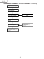
TROUBLE SHOOTING TABLE
Lamp fails to light-up
Turn on the power switch.
Is discharging sound heard from
lamp?
Yes
Is the lamp out of socket?
Yes
Reconnect the lamp into socket.
No
No
Replace the lamp
Is the ballast cooling fan running?
No
Check the power supply circuits.
Yes
Is DC 280V/400V voltage applied
between CN704 connetor pins?
No
Check the power supply circuits.
Yes
Is 2V or higher voltage applied
No
between pins(4) and (2) of ballast’s
CN705 connector.
Is the CN705 connector
disconnected?
Yes
Yes
Replace the ballast.
Reconnect it into socket correctly.
34
No
Check the microproccessor and its
peripheral circuits.
XG-C55X
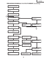
TROUBLE SHOOTING TABLE (Continued)
Checking the power unit
There is no voltage output at
CN708
No
Check the Output PWB unit
Yes
Which output voltage line fails?
Other
Check the T703, IC703, IC705,
IC706 and their peripheral circuits.
BU5.3V
Is AC voltage(90~264V)applied
across the CN701 connector?
No
Check the CN701 or AC cord.
Yes
Is AC voltage(90~264V)applied
across the CN706 connector?
Yes
Yes
Is the resistor R775 open?
No
No
Replace Power unit.
Yes
Is the fuse F701 open?
Replace the F701.
No
Is the resistor R702 open?
Yes
Replace the R702.
No
Is the Bimetal SW open
Yes
Push the red button of the bimetal.
No
Replace Inlet unit.
35
Replace the R775.
XG-C55X
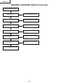
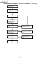
TROUBLE SHOOTING TABLE (Continued)
No audio output
Is the audio signal outputted from
the emmitor of Q306?
No
Check the P301 and its peripheral
circuits.
No
Check the IC303 and its peripheral
circuits.
No
Check theIC302 and its peripheral
circuits.
Yes
Is its signal inputted into pins(2)
and (15) of IC303?
Yes
Is its signal inputted into pins(12)
and (5) or pins(3) and (13) of IC302?
Yes
Is its signal outputted from pins(14) No
and (15) or pins(16) and (17) of
P3102?
Check the Q304 and Q305 and its
peripheral circuits.
Yes
Is its signal inputted into pins(14)
and (15) or pins(16) and (17) of
SC102?
No
Check the connection between
P3102 and SC3102.
Yes
Check the J431, J421 and their
peripheral circuits.
36
XG-C55X
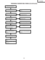
TROUBLE SHOOTING TABLE (Continued)
Checking the video system
Is the lamp on ?
No
Go to "Lamp fails to light-up".
Yes
Is specified voltage EA
connectors?
No
Check power circuit and its parts.
Yes
No
Check the video terminal and its
peripheral circuits.
Is the signal outputted from the pin No
(7) of IC4502?
Check IC4502 and its peripheral
circuits.
Is the video signal inputted into the
pin (23) of P3102?
Yes
Yes
Is the signal outputted from the pin
(5) of IC4505?
No
Check IC4505 and its peripheral
circuits.
No
Check Q4501 and its peripheral
circuits.
Yes
Is the signal inputted into pin (72)
of P8002?
Yes
Go to "Checking the PC I/F unit".
37
XG-C55X
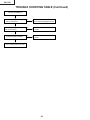
TROUBLE SHOOTING TABLE (Continued)
Checking the S-video system
Is the lamp on ?
No
Go to "Lamp fails to light-up".
Yes
Is specified voltage EA
connectors?
No
Check power circuit and its parts.
Yes
Is the video signal inputted into the
pins (19) and (21) of P3102?
No
Check the video terminal and its
peripheral circuits.
No
Check IC4502 and its peripheral
circuits.
No
Check Q4513 and its peripheral
circuits.
No
Check Q4502 and its peripheral
circuits.
Yes
Is the Y-signal outputted from the
pin (7) of IC4502?
Yes
Is the C-signal outputted from the
emitter of Q4513?
Yes
Is the signal inputted into pins(72)
and (73) of P8002?
Yes
Go to "Checking the PC I/F unit".
38
XG-C55X
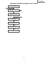
TROUBLE SHOOTING TABLE (Continued)
Checking the RGB signal.
Are the RGB signals outputted from No
pin(16), (18) and (20) of IC3101?
Check IC3101 and its peripheral
circuits.
Yes
Are their signals outputted from
pins(26), (28) and (30) of P3102?
No
Check SC3102, P3102 and
their peripheral circuits.
No
Check Q2419, Q2420 and their
peripheral circuits.
No
Check IC2401, Q2401, Q2402 and
Q2404 and their peripheral circuits.
Yes
Are their signals inputted into
pins(1), (5) and (25)?
Yes
Are their signals inputted into
pins(54), (58) and (62)?
Yes
Are their signals outputted from
pin(45)-(54), pins(57)-(66) and
pins(69)-(78) of P8001?
No
Go to "Checking the PC I/F unit".
Yes
Are their signals inputted into
IC1101, IC1201, IC1301 and
IC1401?
No
Check IC1101, IC1201, IC1301
and IC1401 and their peripheral
circuits.
Yes
Are their signals inputted into
SC1101, SC1201 and SC1301?
Yes
Check the connection of LCD
panels
And when video signal and OSD
are also not displaied, replace the
LCD panels.
39
XG-C55X
TROUBLE SHOOTING TABLE (Continued)
Checking the RGB Sync.
Are the sync inputted into pins(2)
and (4) of SC3102?
No
Check IC3152, IC3153, IC3154,
IC3151 and their peripheral circuits.
Yes
Are their signal inputted into pins(2) No
and (12) of IC2404?
Check P3102 and its peripheral
circuits.
Yes
Are their signal inputted into
pins(63) and (66) of P8002?
No
Check IC2404 and its peripheral
circuits.
Yes
Go to "Checking the PC I/F unit".
40
XG-C55X
TROUBLE SHOOTING TABLE for PC I/F UNIT
Checking of PC I/F UNIT
0
Is the user menu displayed
onscreen?
Yes
Yes
Check the onscreen display.
Check the RGB input.
Yes
Check the component input.
Yes
Check the video input.
Yes
End
41
XG-C55X
TROUBLE SHOOTING TABLE for PC I/F UNIT (Continued)
Checking of Onscreen Display
Is the user menu displayed
onscreen normally by the MENU
key?
Yes
No problem with the onscreen
display.
No
Enter the process menu and select
PATTERN. Then select the COLOR
pattern.
Is the onscreen display color
normal?
No
Yes
In the process mode, make the
LCD line adjustment.
Select the STEP signal.
0
Is the STEP signal as specified?
Yes
No
Rewrite the onscreen display data.
0
Is the signal compatible with the
STEP signal outputted at TL106
thru TL111?
Yes
No
IC8025 is defective.
Go to "Checking of GA4 and Its
Periphery".
Rewrite the onscreen display data.
42
XG-C55X
TROUBLE SHOOTING TABLE for PC I/F UNIT (Continued)
Checking of RGB Input
Feed the sync separation type
analog RGB signal to INPUT1.
1
Select INPUT1 using the set’s key
or the remote controller.
2
Does the picture appear?
No
Yes
Is the picture disturbed?
Yes
Go to "Confirmation of Video
Input".
No
3
Go to "Checking of Sync Signal".
Do the three colors R, G and B
appear?
No
Yes
Go to "Checking of RGB Signal".
Carry out the AUTOSYNC process.
Is the contour of picture clear?
No
Yes
Is there any disturbance in the
vertical stripe pattern?
No
Yes
IC8013, IC8025 or their periphery
is defective.
End
43
XG-C55X
TROUBLE SHOOTING TABLE for PC I/F UNIT (Continued)
Confirmation of Video Input
Make "Confirmation of Input
Signal Setting".
Is there the video signal at the land
of C8070?
No
Yes
Is there the signal at pin (55) of
SC8002 (B-to-B connector)?
Go to "Checking of Sync Signal".
Yes
Somewhere in the signal route is
defective. Check the capacitors
and resistors between SC8002
and IC8013.
IC8025 or IC8013 is defective.
The signal source or connector is
defective.
Confirmation of Input Signal
Setting
Is the right item selected from input
menu?
No
Yes
Select the right item.
2
Are the connectors connected
correctly?
No
Yes
Connect the connectors correctly.
End
1
44
No
XG-C55X
TROUBLE SHOOTING TABLE for PC I/F UNIT (Continued)
Checking of Sync Signal
Is there the vertical sync signal at
pin (11) of IC8363?
No
Yes
Is there the horizontal sync signal
at pin (5) of IC8363?
No
Yes
Make confirmation of input signal
setting.
R997, R996, SC8002 or their
periphery is defective.
Is there the vertical sync signal at
TL8131?
No
Yes
Is there the horizontal sync signal
at TL8130?
No
Yes
Are both the vertical and horizontal
sync signals in appropriate timing?
IC8363 is defective.
Yes
No
The sync signals are as specified.
End of checking.
Is the signal generator
(input source) appropriate?
Yes
No
Set the signal source
appropriately.
R997, R996, SC8002 or their
periphery is defective.
2
45
XG-C55X
TROUBLE SHOOTING TABLE for PC I/F UNIT (Continued)
Checking of R, G and B Signals
Is the signal type set to RGB?
No
Yes
Set the signal type to RGB.
Set the process mode.
Select R, G and B individually on
the pattern menu.
Go to "Checking of GA4 and Its
Periphery".
For checking the input signal, set
the signal generator to gradation
signal.
Measure the signals at TL8169,
TL8170 and TL8180 on the
oscilloscope. (MSB bit after A/D
conversion)
Are there the specified signals at
TL8169, TL8170 and TL8180?
Yes
IC8025 or its periphery is defective.
No
Does the signal come to C8062,
C8070 and C8078?
No
Yes
IC8013 or its periphery is defective.
46
Go to "Confirmation of Video Input".
XG-C55X
TROUBLE SHOOTING TABLE for PC I/F UNIT (Continued)
Checking of GA4 and Its Periphery
Select R, G and B individually on
the pattern menu in the process
mode.
Is picture outputted appropriately
in R, G and B?
Yes
No
Checking of GA4 and its periphery
ends.
Measure the signals at pins (54),
(66) and (78) of SC8001 on the
oscilloscope. These signals are
MSB of B/G/R/.
Do the oscilloscope-measured
signals match with those selected
on the pattern menu?
Yes
No
The OUTPUT PWB is defective.
Does the clock signal come to pins No
(40) and (42) of SC8001?
Yes
Is there the clock (37.5 MHz)
signal at TL8114?
Yes
No
IC8029 is defective.
Is there the clock (37.5 MHz)
signal at FL8110?
Measure the signals at TL8106,
TL8107, TL8108, TL8110 and
TL8111 on the oscilloscope.
Yes
X8005 is defective.
IC8025 is defective.
Do the oscilloscope-measured
signals match with those selected
on the pattern menu?
Yes
No
No
IC8025 is defective.
IC8029 is defective.
47
XG-C55X
TROUBLE SHOOTING TABLE for PC I/F UNIT (Continued)
Checking of Component Input
(except 480I)
Feed the component signal to
INPUT1.
Select INPUT1 using the set’s key
or the remote controller.
Does the picture appear?
No
Yes
4
Go to "Checking of SOG Circuit".
Are the colors normal?
No
Is the signal type set at
component?
No
Yes
Set the signal type to component.
Carry out the process adjustment.
4
Is the contour of picture clear?
No
Yes
The component is normal. End.
IC8013 or IC8025 is defective.
48
XG-C55X
TROUBLE SHOOTING TABLE for PC I/F UNIT (Continued)
Checking of SOG Circuit
Measure the signal at pin (2) of
IC8365 on the oscilloscope.
Is the composite sync signal
reproduced in correct timing?
Yes
No
The SOG circuit is normal. End.
Measure the land of C8070 on the
oscilloscope.
Is there the Y signal including sync No
signal?
Yes
The SOG sync separation circuit
(INPUT PWB) is defective.
Go to "Confirmation of Input Signal
Setting".
49
XG-C55X
TROUBLE SHOOTING TABLE for PC I/F UNIT (Continued)
Checking of Video Input
Feed the composite video signal
to INPUT3.
Select INPUT3 using the set’s key
or the remote controller.
5
Does the picture appear?
No
Yes
Is there any disturbance in the
picture?
Go to "Checking of Video
Sync Signal".
Yes
No
Are the colors normal?
Go to "Checking of Video
Sync Signal".
Carry out the process
adjustment.
No
5
Yes
The video input is normal. End.
Is the video signal inputted to
C8141?
No
Yes
Is there the signal at R8114?
6
Yes
Q8002 or its periphery is
defective.
The INPUT/OUTPUT PWB is
defective.
50
No
No
Is there the signal at pin (3)
of SC8002?
Yes
R8114 or its periphery is
defective.
XG-C55X
TROUBLE SHOOTING TABLE for PC I/F UNIT (Continued)
6
Check the clock signal of IC8015
by FL8114.
Is the clock signal normal?
No
Yes
IC8015 is defective.
Go to "Checking of Video Sync
Signal".
IC8025 or its periphery is defective.
Checking of Video Sync Signal
Measure the signal at pin (10) of
IC8363 on the oscilloscope.
(Checking of vertical sync signal)
Is the vertical sync signal normal?
No
Yes
Measure the signal at pin (6) of
IC8363 on the oscilloscope.
(Checking of horizontal sync signal)
Is the horizontal sync signal
normal?
No
Go to "Confirmation of Input
Signal Setting".
Yes
7
51
XG-C55X
TROUBLE SHOOTING TABLE for PC I/F UNIT (Continued)
7
Are the horizontal and vertical sync
signals outputted at TL8130 and
TL8131, respectively?
No
IC8015 or its periphery is
defective.
Yes
Is there the specified clock
(13.5 MHz) signal at FL8114?
Yes
No
IC8015 or its periphery is
defective.
End.
52
XG-C55X
Technische Daten
Produkttyp LCD PROJEKTOR
Modell XG-C55X
Videosystem NTSC 3.58/NTSC 4.43/PAL/PAL-M/PAL-N/PAL 60/SECAM/
DTV480I/DTV480P/DTV540P/DTV580I/DTV580P/DTV720P/DTV1035I/DTV1080I
Wiedergabeverfahren LCD-Panel × 3, optische RGB-Verschlussmethode
LCD-Panel Panel-Größe: 0,99tum(25,1 mm)(15 [H] × 20 [B] mm)
Anzahl der Bildpunkte: 786.432 Bildpunkte (1.024 [H] × 768 [V])
Standard-Objektiv 1—1,27× Zoom-Objektiv, F1,7—2,2,f = 36,5—46,3mm
Projektionslampe Wechselstromlampe SHP 300 W
Komponenten-Eingangssignale 15-poliger Mini-D-Sub-Anschluss
(INPUT 1/2) Y: 1,0 Vs-s, negatives Sync., 75 Ω terminiert
PB: 0,7 Vs-s, 75 Ω terminiert
PR: 0,7 Vs-s, 75 Ω terminiert
Horizontale Auflösung 750 Fernsehzeilen (DTV720P)
Computer-RGB-Eingangssignal 15-poliger Mini-D-Sub-Anschluss
(INPUT 1/2) RGB getrennt/Sync auf Grün-Typ analoger Eingang: 0-0,7 Vs-s, positiv, 75 Ω terminiert
HORIZONTALES SYNC.-SIGNAL: TTL-Pegel (positiv/negativ)
VERTIKALES SYNC.-SIGNAL: Wie oben
Videoeingangssignal RCA-Anschluss: VIDEO, gemischtes Video, 1,0 Vs-s, negatives Sync., 75 Ω terminiert
(INPUT 3)
S-Videoeingangssignal 4-pol. Mini DIN-Anschluss
(INPUT 4) Y (Luminanzsignal): 1,0 Vs-s, negatives Sync., 75 Ω terminiert
C (Chrominanzsignal): Stoß 0,286 Vs-s, 75 Ω terminiert
Computer-Steuerungssignal (RS-232C) 9-Pin Mini-DIN-Stecker
Pixeltakt 12-230 MHz
Vertikale Frequenz 43-200 Hz*
Horizontale Frequenz 15-126 kHz
Audioeingangssignal ø3,5 mm Minibuchse: AUDIO, 0,5 Vrms, mehr als 47 kΩ (Stereo)
Audioausgang 3,0 W (Mono)
Lautsprechersystem 4 cm × 7 cm
Nennspannung 100-240 V Wechselstromspannung
Eingangsspannung 4,0 A
Nennfrequenz 50/60 Hz
Leistungsaufnahme 400 W (Standard-Modus)/325 W (Modus mit niedrigem Stromverbrauch)bei AC 100 V
380 W (Standard-Modus)/310 W (Modus mit niedrigem Stromverbrauch)bei AC 240 V
Leistungsaufnahme 0,5 W (bei AC 100 V)-0,8 W (bei AC 240 V) (wenn “Monitor/RS232” auf “OFF” gestellt ist)
(Bereitschaft) 1.505 BTU/Stunde (Standard-Modus)/1.220 BTU/stunde (Modus mit niedrigem Stromverbrauch)bei AC 100 V
W ä rmeableitung 1.430 BTU/Stunde (Standard-Modus)/1.165 BTU/stunde (Modus mit niedrigem Stromverbrauch)bei AC 240 V
41°F bis 104°F (+5°C bis +40°C)
Betriebstemperatur – 4°F bis 140°F (–20°C bis +60°C)
Lagertemperatur Plastik
Gehäuse 38 kHz
I/R-Trägerfrequenz 15 3⁄8" × 3 7⁄8" × 11 9⁄16" (390 (B) × 99 (H)× 294 (T) mm) (nur Hauptgerät)
Abmessungen (ca.) 15 1⁄2" × 4 7⁄16" × 11 5⁄8" (393 (B) × 114 (H) × 303 (T) mm) (einschließlich Drehfüße und Projektionsteile)
Gewicht (ca.) 11,3 lbs. (5,1 kg)
Mitgeliefertes Zubehör Fernbedienung, zwei R6-Batterien, Netzkabel für USA, Kanada usw. (11'10", 3,6 m), Netzkabel für Europa, ausgenommen
Großbritannien (6', 1,8 m), Netzkabel für Großbritannien, Hongkong und Singapur (6', 1,8 m), Netzkabel für Australien, Neuseeland
und Ozeanien (6', 1,8 m), RGB-Kabel (9' 10", 3 m), USB-Kabel 3'3", 1 m), (DIN-D-Sub RS-232C-Adapter (5 57⁄64", 15 cm),
Fernbedienungsempfänger, Zusätzlicher Luftfilter, Objektivkappe (befestigt), Projektorhandbuch-und technische Referenz-CDROM, Sharp Advanced Presentation Software CD-ROM, Schnell-Installationsanleitung für die Sharp Advanced Presentation
Software, “QUICK GUIDE (Schnellanleitung)”-Aufklebers, Bedienungsanleitung
Ersatzteile Lampeneinheit (Lampen-/Gehäusemodul) (BQC-XGC55X//1), Fernbedienung (RRMCGA176WJSA), zwei R 6-Batterien (“AA”,
UM/SUM-3, HP-7 oder ähnlich), Netzkabel für USA, Kanada usw. (QACCDA010WJPZ), Netzkabel für Europa, ausgenommen
Großbritannien (QACCVA011WJPZ), Netzkabel für Großbritannien, Hongkong und Singapur (QACCBA012WJPZ), Netzkabel
für Australien, Neuseeland und Ozeanien (QACCLA014WJPZ),RGB-Kable (QCNWGA012WJPZ), USB-Kabel
(QCNWG0007CEPZ), DIN-D-Sub RS-232C-Adapter (QCNWGA015WJPZ), Fernbedienungsempfänger (RUNTKA061WJZZ),
Luftfilter (PFILDA005WJZZ), Objektivkappe (PCAPHA003WJSA), Projektorhandbuch-und- technische Referenz-CD-ROM
(UDSKAA035WJZZ), Sharp Advanced Presentation Software CD-ROM (UDSKAA036WJZZ), Schnell-Installationsanleitung für
die Sharp Advanced Presentation Software (TINS-A867WJZZ), “QUICK GUIDE (Schnellanleitung)”-Aufklebers
(TLABZA364WJZZ), Bedienungsanleitung (TINS-A812WJZZ)
*Bei vertikalen Frequenzen über 100 Hz kann eine zeitweise Störung sichtbar werden, wenn die OSD-Funktionen eingeschaltet sind.
Bedingt durch fortlaufende technische Verbesserungen behält sich SHARP das Recht vor, das Design und die Spezifikationen ohne vorherige Ankündigung ändern zu können. Die angegebenen
Leistungswerte stellen die Nennwerte einer in Serienherstellung produzierten Einheit dar. Geringe
Abweichungen bei einzelnen Geräten sind möglich.
53
XG-C55X
HINWEIS FÜR DAS WARTUNGSPERSONAL
12345678901234567890123456789012123456789012345
12345678901234567890123456789012123456789012345
Ë Auswechseln der Lampe
ACHTUNG: UV-STRAHLUNG
12345678901234567890123456789012123456789012345
12345678901234567890123456789012123456789012345
12345678901234567890123456789012123456789012345
Hinweis:
Da die Lampe während des Betriebs sehr heiß wird,
sollte die Lampe erst ausgewechselt werden, nachdem
das Gerät mindestens eine Stunde ausgeschaltet war,
damit die Lampe ausreichend abkühlen kann.
Beim Installieren der neuen Lampe muß darauf
geachtet werden, die Lampe selbst (Glaskolben)
nicht zu berühren. Vielmehr muß die Lampe am
Reflektor 2 gehalten werden.
[Es darf nur ein Original-Ersatzteil verwendet
werden.]
Die Lichtquelle im Projektor, eine Metall-HalogenLampe, gibt eine geringe UV-Strahlung ab.
DIREKTE BESTRAHLUNG AUF AUGEN
UND HAUT MUSS VERMIEDEN WERDEN.
Zur Gewährleistung der Sicherheit muß folgendes
beachtet werden:
1. Bei Arbeiten am Projektor bei eingeschalteter
Lampe und abgenommenem oberen Gehäuse
muß unbedingt eine Sonnenbrille getragen
werden.
1 Lampe
2 Reflektor
GEFAHR! — Niemals die Spannungsversorgung
einschalten, ohne daß eine Lampe vorhanden ist,
um elektrische Schläge und Schäden am Gerät zu
vermeiden, da der Stabilisator anfangs hohe
Spannungen erzeugt.
2. Die Lampe darf nicht außerhalb des
Lampengehäuses eingeschaltet werden.
Da eine geringe UV-Strahlung aus einer Öffnung
zwischen der Schachtabdeckung und dem
Lampengehäuse austritt, sollte der Objektivdeckel
bei Wartungsarbeiten auf die Öffnung gesetzt
werden, um die Bestrahlung von Augen und Haut
zu vermeiden.
3. Betrieb für länger als 2 Stunden bei
abgenommenem Gehäuse ist nicht zulässig.
Vorsichtsmaßnahmen gegen UVStrahlung und Hochdrucklampe
1. Vor dem Auswechseln der Lampe muß der
Netzstecker gezogen werden.
2. Vor Durchführung von Wartungsarbeiten muß das
Gerät eine Stunde abkühlen.
3. Nur mit dem gleichen Lampentyp ersetzen Typ BQCXGC50X//1; Nennleistung 80 V/300 W.
4. Die Lampe gibt eine geringe UV-Strahlung ab, daher
muß direkter Augenkontakt vermieden werden.
5. B e i d e r H o c h d r u c k l a m p e b e s t e h t e i n e
Explosionsgefahr. Auf jeden Fall den unten
beschriebenen Installationsanweisungen folgen und
die Lampe vorsichtig behandeln.
54
XG-C55X
Vorsichtsmaßregeln für bleifreien Lötzinn
1 Verwendung von bleifreiem Lötzinn
Die "Eingangs-, Ausgangs-, Fernbedienungs-, Schlüsell-, AC-Eingangs-, Netz-, Gebläse-Platine" dieses Modells
verwendet bleifreien Lötzinn. Das LF-Symbol zeigt bleifreien Lötzinn an und ist an den Platinen und
Wartungsanleitungen angebracht. Der Buchstabe nach LF zeigt den Typ des bleifreien Lötzinns an.
Beispiel:
LFa
Zeigt bleifreien Lötzinn aus Zinn, Silber und Kupfer an.
2 Bei Reparatur der mit bleifreiem Lötzinn gelöteten Platine immer bleifreien Lötzinn verwenden. Reparatur mit
herkömmlichem Lötzinn kann zu Schäden oder Unfällen aufgrund von Rissen führen.
Da der Schmelzpunkt bleifreien Lvtzinns (Sn-Ag-Cu) um 40°C höher als der von Bleidraht-Lötzinn ist, empfehlen
wir die Verwendung einer speziellen Lötspitze. Wenn Fragen über den Beschaffung leitfreien Lötzinns oder spezieller
Lötspitzen bestehen, wenden Sie sich an unsere Kundendienstvertretung in Ihrem Gebiet.
3 Löten
Da der Schmelzpunkt bleifreien Lötzinns (Sn-Ag-Cu) etwa 220°C beträgt, was um 40°C höher als der von bleihaltigem
Lötzinn ist, und außerdem schlechte Löt-Benetzbarkeit aufweist, kann es erforderlich werden, die Lötspitze längere
Zeit in Kontakt mit der Platine zu halten. Da die Lötlauge abfliessen kann oder der maximale Hitzewiderstand von
Teilen überschritten werden kann, die Lötspitze sofort von der Platine nehmen, sobald eine gute Lötung erzielt ist.
Bleifreier Lötzinn enth_lt mehr Zinn, und das Ende der Lötspitze kann leicht angegriffen werden. Immer sicherstellen,
dass der Lötkolben nur bei Bedarf eingeschaltet wird.
Wenn ein anderer Typ von Lötzinn an der Lötspitze haften bleibt, verschmilzt er mit dem bleifreien Lötzinn. Die
Lötspitze nach jeder Verwendung reinigen.
Wenn die Lötspitze bei der Verwendung geschwärzt wird, die Spitze mit Stahlwolle oder feinem Sandpapier
abschmirgeln.
Immer beim Austausch von Teilen vorsichtig sein, und die Polaritätsanzeige auf der Platinenbeschriftung beachten.
Bleifreier Lötzinn zur Wartung
Teile-Nr.
ZHNDAi123250E
ZHNDAi126500E
ZHNDAi12801KE
★
J
J
J
Beschreibung
φ0.3mm
250g(1roll)
φ0.6mm
500g(1roll)
φ1.0mm
1 Rolle
55
Code
BL
BK
BM
XG-C55X
Bedienungsanleitung
Projektor (Vorder- und Draufsicht)
ON-Taste
INPUT-Taste
Schaltet die
Stromversorgung ein.
Für das Umschalten zwischen
Eingangsmodus 1, 2, 3 und 4.
Netz-Anzeige
KEYSTONE-Taste
Leuchtet rot, wenn sich der
Projektor im Bereitschaftsbetrieb
befindet. Wenn die
Stromversorgung eingeschaltet
ist, leuchtet diese Anzeige grün.
Für das Einstellen der
Trapezverzerrungs- oder Digitalen
Verschiebungs-Einstellung.
AUTO SYNC-Taste
STANDBY-Taste
Schaltet den Projektor in
den Standby-Modus.
Für das automatische Einstellen
von Bildern, wenn ein Computer
angeschlossen ist.
STANDBY
Lampen-Anzeige
Einstelltasten
(', ", \, |)
Bei vorschriftsmäßiger Funktion
leuchtet diese Anzeige grün. Die
Lampe austauschen, wenn die
Anzeige rot leuchtet.
Für die Wahl der Menüpunkte.
VOL-Tasten
Für das Einstellen des
Lautsprecher-Tonpegels.
TemperaturwarnAnzeige
Wenn die interne Temperatur
ansteigt, leuchtet diese
Anzeige rot.
MENU-Taste
UNDO-Taste
Für das Rückgängigmachen
eines Bedienschrittes oder für
die Rückkehr zu den
Grundeinstellungen.
ENTER-Taste
Für die Anzeige des Justierungsund Einstellungsbildschirms.
Für die Einstellung der
gewählten oder eingestellten
Menüpunkte.
HEIGHT
ADJUST-Taste
Zoom-Knopf
Fokusring
Einstellfuß
Luftzufuhr
Tragegriff
Fernbedienungssensor
Anbringen und Abnehmen der Objektivkappe
• Drücken Sie an den beiden Tasten der
Objektivkappe, und bringen Sie diese an dem
Objektiv an. Danach geben Sie die Tasten frei, um
die Objektivkappe zu verriegeln.
• Drücken Sie die beiden Tasten der Objektivkappe,
und nehmen Sie die Objektivkappe von dem
Objektiv ab.
56
Luftfilter/Ventilator
(Luftzufuhr)
(auf der Unterseite
des Projektors)
XG-C55X
Projektor (Hin ters icht )
AUDIO INPUT 1, 2Anschluss
RS-232C-Anschluss
Für die Bedienung des
Projektors über
Computers.
Geteilter
Audioeingabeanschluss
für INPUT 1 und 2.
AUDIO OUTPUTAnschluss
WIRED REMOTEEingabeanschluss
Geteiltes Audio
Ausgabeanschluss für
INPUT 1, 2, 3 und 4.
INPUT 3-Anschluss
Für den Anschluss eines
Videogerätes.
INPUT 1-Anschluss
Anschluss für Computer
RGB und
Komponentensignale.
AUDIO (L/R) INPUT
3, 4-Anschlüsse
Geteilter
Audioeingabeanschluss
für INPUT 3 und 4.
OUTPUT (INPUT 1, 2)Anschluss
Geteilter Computer-RGBund KomponentensignaleAusgabeanschluss für
INPUT 1 und 2.
INPUT 4-Anschluss
Anschluss für ein
Videogerät mit einem SVIDEO-Anschluss.
INPUT 2-Anschluss
Anschluss für Computer
RGB und
Komponentensignale.
Netzanschluss
Luftaustritt-öffnung
KensingtonSicherheitsstandardanschluss
Einstellfuß
Verwendung der Kensington-Sperre
• Dieser Projektor ist mit einem Kensington-Sicherheitsstandardanschluss für die Verwendung des Kensington
MicroSaver-Sicherheitssystem ausgestattet. Lesen Sie hinsichtlich der Verwendung die Informationen, die
dem System beiliegen, um den Projektor zu sichern.
Transportieren des Projektors
Bevor Sie den Projektor
transportieren, muss der Tragegriff
vollkommen ausgeklappt werden.
57
XG-C55X
Fernbedienung (Vordersicht)
STANDBY-Taste
ON-Taste
Schaltet den Projektor in den
Standby-Modus.
Schaltet die Stromversorgung ein.
MENU-Taste
KEYSTONE-Taste
Für die Anzeige des Justierungs- und
Einstellungsbildschirms.
Zur Einstellung des Keystone oder
Digital Shift.
Einstelltasten (', ", \, |)
ENTER-Taste
Für die Wahl der Menüpunkte.
Für die Einstellung der gewählten oder
eingestellten Menüpunkte.
PinP-Taste
Zur Anzeige von Doppelbildern.
UNDO-Taste
Für das Rückgängigmachen eines
Bedienschrittes oder für die Rückkehr zu
den Grundeinstellungen.
FORWARD/BACK-Tasten
Gleiche Funktion wie die [Page Down]und [Page Up]-Tasten auf der ComputerTastatur, wenn der
Fernbedienungsempfänger verwendet
wird.
ENLARGE-Tasten
(Vergrößern/Verkleinern)
Für das Vergrö§ern oder Verkleinern eines
Bildteils.
FREEZE-Taste
GAMMA-Taste
Für das Einfrieren von Bildern.
Für das Korrigieren der Helligkeit eines
Bildes, wenn das angezeigte Bild aufgrund
der Raumhelligkeit schwierig zu sehen ist.
Sie können aus vier verfügbaren GammaModi auswählen.
BLACK SCREEN-Taste
Schwarzüberlagerung des Bildschirms.
RESIZE-Taste
Für das Umschalten der Bildwandgröße
(NORMAL, UMRANDLING usw).
AUTO SYNC-Taste
Für das automatische Einstellen von
Bildern, wenn ein Computer
angeschlossen ist.
MUTE-Taste
Zum zeitweisen Stummschalten.
INPUT-Tasten
Zum Umschalten auf die entsprechenden
Eingabemodi.
BREAK TIMER-Taste
Zur Anzeige des Pausentimers.
VOL-Tasten
Für das Einstellen des LautsprecherTonpegels.
Fernbedienung (Draufsicht)
WIRED R/C JACK
Fernbedienungsanschluss an den Projektor.
Signalsender für Fernbedienung
58
XG-C55X
Pin-Belegung
INPUT-1/2-RGB und OUTPUT-Signalanschluss: 15-Pin Mini-D-Sub weiblich
RGB-Eingabe
1
6
11
5
10
15
1.
2.
3.
4.
5.
6.
7.
8.
9.
10.
11.
12.
13.
14.
15.
Komponenteneingabe
Videoeingabe (rot)
Videoausgabe (grün/sync auf grün)
Videoausgabe (blau)
Nicht angeschlossen
Nicht angeschlossen
Erde (rot)
Erde (grün/sync auf grün)
Erde (blau)
nicht angeschlossen
GND
Nicht angeschlossen
Bi-directionale Daten
Horizontal-Sync-Signal : TTL level
Vertikal-Sync-Signal : TTL level
Datenuhr
1.
2.
3.
4.
5.
6.
7.
8.
9.
10.
11.
12.
13.
14.
15.
PR (CR)
Y
PB (CB)
Nicht angeschlossen
Nicht angeschlossen
Erde (PR)
Erde (Y)
Erde (PB)
Nicht angeschlossen
Nicht angeschlossen
Nicht angeschlossen
Nicht angeschlossen
Nicht angeschlossen
Nicht angeschlossen
Nicht angeschlossen
RS-232-Anschluss: 9-Pin Mini-DIN weiblich
8
9
7
6
3
Pin-Nr.
1
2
3
4
5
6
7
8
9
Signal
Name
RD
SD
Daten empfangen
Daten senden
SG
Signalgrund
I/O
Ausgabe
Eingabe
Ausgabe
Eingabe
Eingabe
Ausgabe
Eingabe
Ausgabe
RS
CS
Referenz
Nicht angeschlossen
interner Stromkreisanschluss
interner Stromkreisanschluss
Nicht angeschlossen
interner Stromkreisanschluss
Nicht angeschlossen
Angeschlossen an Pin 8
Angeschlossen an Pin 7
Nicht angeschlossen
4
5
2
1
9-Pin D-Sub männlicher Anschluss des DIN-D-Sub-RS-232C-Adapter
1
6
5
9
Pin-Nr.
1
2
3
4
5
6
7
8
9
Signal
CD
RD
SD
ER
SG
Name
I/O
Daten empfangen
Daten senden
Eingabe
Ausgabe
Signalgrund
RS
CS
CI
Referenz
Nicht angeschlossen
interner Stromkreisanschluss
interner Stromkreisanschluss
Nicht angeschlossen
interner Stromkreisanschluss
Nicht angeschlossen
interner Stromkreisanschluss
interner Stromkreisanschluss
Nicht angeschlossen
Hinweis
• Pin 8(CS) und Pin 7(RS) sind im Innern des Projektors kurzgeschlossen.
RS-232C Kabel empfohlene Verbindung: 9-Pin-D-Sub weiblich
5
9
1
6
Pin-Nr.
1
2
3
4
5
6
7
8
9
Signal
CD
RD
SD
ER
SG
DR
RS
CS
CI9
Pin-Nr.
1
2
3
4
5
6
7
8
Signal
CD
RD
SD
ER
SG
DR
RS
CS
CI
Hinweis
• Je nach verwendetem Steuergerät ist es unter Umständen erforderlich, Pin 4 und Pin 6 am Steuergerät (z.B.
am PC) anzuschließen.
Projektor
Pin-Nr.
4
5
6
PC
Pin-Nr.
4
5
6
59
XG-C55X
Abmessungen
Ansicht von
oben
Ansicht von
der Seite
3/16
(5,2)
11 9/16 (294)
8 7/16 (213,3)
Ansicht von
der Seite
1/8 (4)
Ansicht
von hinten
1/16
(1,5)
15 3/8 (390)
1/16
2 1/8
1 3/4
(54,5) (44,5)
3 1/8 (80)
(15)
Ansicht von
vorne
3 15/16 (99)
5 (126,5)
9/16
9 1/2 (241,5)
3 15/16 (100,5)
4 3/8 (111,75)
2 15/16 (75)
(7,5)
5/16
4 15/16 (124,5)
2 11/16 (67,5)
M4
M4
4 1/8 (104)
Ansicht von
unten
M4
M4
60
¿ 67,5
(1,5)
XG-C55X
AUSBAU WICHTIGER TEILE
1. Ausbau von Bodenfilter-Abdeckung und Lampeneinheit-Abdeckung
1-1.
1-2.
1-3.
1-4.
Bodenfilter-Abdeckung abtrennen.
Die Sperrschraube von der Lampeneinheit-Abdeckung lösen und die Lampeneinheit-Abdeckung abnehmen.
Den Tragegriff herausziehen.
Die mit * markierte Stelle auf der oberen Hälfte der Objektiv-Abdeckung drücken, um die Klaue zu lösen, und
dann die obere Objektiv-Abdeckung entfernen.
1-5. Die untere Hälfte der Objektiv-Abdeckung entfernen.
2. Oberplatte und Rückplatte entfernen
2-1. Sechs Sperrschrauben (schwarz) von der Oberplatte entfernen.
2-2. Die acht Sperrschrauben von der Rückplatte entfernen, und die Rückplatte abnehmen.
( 2-2 :XEBSF30P12000, 2-2 :XBBSF30P10000)
2-3. Langsam die Oberplatte anheben und den Steckverbinder von der Schlüssel-Leiterplatte abtrennen. Eine
andere Schraube entfernen, und die Oberplatte abnehmen.
Lampeneinheit-Abdeckung
1-2
1-4
Obere Hälfte der
Objektiv-Abdeckung
1-3
1-1
Tragegriff
1-5
Untere Häfle der
Objektiv-Abdeckung
Oberplatte
Bodenfilter-Abdeckung
2-2
2-2
2-3
Rückplatte
2-1
(Schwarz)
61
XG-C55X
3. Entfernen der Leiterplatten
3-1.
3-2.
3-3.
3-4.
3-5.
Die zwei Sperrschrauben vom Lampenfassung-Winkel entfernen. Den Lampenfassung-Winkel abtrennen.
Die Ballast-Einheit anheben. Den Steckverbinder abtrennen, und die Ballast-Einheit abtrennen.
Die Sperrschraube von der Leiterplatten-Einheit-Abdeckung lösen und die Abdeckung abnehmen.
Die drei Sperrschrauben vom Kühlgebläse entfernen.
Die zwei Sperrschrauben vom Kühlgebläse entfernen, den Steckverbinder abtrennen, und das Kühlgebläse
abnehmen.
3-6. Die Sperrschraube von der Masseklemme entfernen, den Steckverbinder abtrennen, und die AC-EingangLeiterplatte abnehmen.
4. Entfernen von Optik-Mechanismus, Gebläse-Leiterplatte, Strom-Leiterplatte und R/CEmpfänger-Leiterplatte.
4-1. Den Anschluss trennen, dann die Lautsprecher-Einheit abnehmen.
4-2. Die acht Sperrschrauben vom Optik-Mechanismus entfernen, und den Optik-Mechanismus herausnehmen.
4-3. Die Sperrschraube vom Kühlgebläse entfernen, den Steckverbinder abtrennen, und die KühlgebläseLeiterplatte abnehmen.
4-4. Die vier Sperrschrauben von der Strom-Leiterplatte entfernen, und die Strom-Leiterplatte abnehmen.
4-5. Die R/C-Empfänger-Leiterplatte herausnehmen.
3-5
3-4
3-4
Kühlgebläse
Leiterplatten-Baugruppen
3-1
3-5
Ballast-Einheit
3-6
3-2
AC-Eingang-Leiterplatte
4-3
4-2
Kühlgebläse
Gebläse-Leiterplatte
3-3
4-2
Leiterplatten-Baugruppen-Abdeckung
4-4
Strom-Leiterplatte
4-1
R/C-Empfänger-Leiterplatte
62
4-2
XG-C55X
RÜCKSTELLUNG DES LAMPEN-TIMERS
Den Lampen-Timer nach dem Lampenaustausch
zurückzustellen.
1
Das Netzkabel anschließen.
Das Netzkabel am Netzanschluss des
Projektors anschließen.
2
Den Lampen-Timer zurückstellen.
Während
,
und
auf dem
Projektor gleichzeitig gedrückt wird,
ON
Netzanschluss
auf dem Projektor drücken.
INPUT-Taste
“LAMPE 100%” erscheint und zeigt
damit an, dass der Lampen-Timer
zurückgestellt ist.
ENTER-Taste
ON-Taste
Info
Stellen Sie sicher, dass Sie den LampenTimer nur nach dem Austausch der
Lampe zurücksetzen. Wenn Sie den
Lampen-Timer zurücksetzen und
dieselbe Lampe weiterhin verwenden,
könnte die Lampe beschädigt werden
oder explodieren.
UNDO-Taste
■ Die Warnleuchten auf dem Projektor weisen auf Fehlfunktionen im Projektor hin.
■ Falls ein Problem auftritt, leuchtet entweder die Temperaturwarn-Anzeige oder die Lampen-Anzeige
rot auf und der Projektor wird in den Standby-Modus geschaltet. Nachdem der Projektor in den
Standby-Modus geschaltet worden ist, den unten aufgeführten Schritten folgen.
Über die Lampen-Anzeige
Netz-Anzeige
Lampen-Anzeige
TemperaturwarnAnzeige
■ Die restliche Betriebszeit der Lampe sinkt auf
0%, wenn sie ungefähr 3.000 Stunden im
“Stromsparmodus” bei der Option “ON”
verwendet wurde oder nach ungefähr 2.000
Stunden im “Stromsparmodus” bei der Option “OFF”.
■ Wenn die restliche Betriebszeit der Lampe
auf 5% oder weniger absinkt, wird “
” auf
dem Bildschirm in gelb eingeblendet. Wenn
” auf
der Prozentsatz 0% wird, ändert “
“
” (rot), worauf die Lampe automatisch
ausgeschaltet und danach der Projektor
automatisch in den Standby-Modus
geschaltet wird. Gleichzeitig leuchtet die
Lampen-Anzeige rot auf.
■ Nachdem Sie zum vierten Mal versucht haben
den Projektor einzuschalten, ohne dass die
Lampe ausgetauscht wurde, kann der
Projektor nicht mehr eingeschaltet werden.
Über die Temperaturwarn-Anzeige
Wenn der Projektor wegen Problemen
bei der Aufstellung oder wegen
Blockierens der Luftöffnungen zu warm
” in der unteren
wird, blinkt “
linken Ecke des Bildes. Wenn die
Temperatur weiter ansteigt, schaltet sich
die Lampe aus und die TemperaturwarnAnzeige blinkt; der Kühlventilator dreht
sich für weitere 90 Sekunden und
anschließend wird der Projektor in den
Standby-Modus geschaltet. Nachdem
” angezeigt wird, unbedingt die
“
folgenden Maßnahmen durchführen.
Wartungsanzeige
Unnormal
Normal
TemperaturwarnAnzeige
Aus
Symptom
Die Temperatur
im Inneren des
Rot ein/
Bereitschaft Gerätes ist zu
hoch.
Rot blinkt /
Rot
eingeschaltet
LampenAnzeige
Grün ein
Grün blinkt,
wenn die Lampe
aufgewärmt
oder
ausgeschaltet
wird.
NetzAnzeige
Grün
eingeschaltet /
Rot blinkt
Rot
eingeschaltet
Problem
Abhilfe
• Belüftungsöffnungen blockiert. • Den Projektor an einem besser
belüfteten Ort aufstellen.
• Den Projektor einem von Sharp
• Kühlventilator beschädigt
• Interne Schaltkreise beschädigt autorisierten Händler für Projektoren oder
dem Kundendienst zur
• Luftfilter verstopft
Reparatur geben.
Die Lampe muss • Restliche Betriebszeit der
ausgetauscht
Lampe sinkt auf 5% oder
werden
weniger ab.
Rot ein/
Die Lampe
Bereitschaft leuchtet nicht.
Die Netz-Anzeige
blinkt bei
eingeschaltetem
Projektor rot auf.
• Ersetzen Sie die Lampe.
• Den Projektor einem von Sharp autorisierten
Händler für Projektoren oder dem
Kundendienst zur Reparatur
oder zum Lampenaustausch geben.
• Ausgebrannte Lampe
• Lassen Sie beim Austausch der Lampe
• Lampen-Schaltkreis beschädigt bitte die nötige Vorsicht walten.
• Befestigen Sie die Abdeckungen sicher.
• Sollte die Netzanzeige auch bei korrekt
• Die Filterabdeckung, die
Abdeckung der Lampeneinheit eingesetzter Filterabdeckung rot aufblinken,
dann wenden Sie sich bitte an Ihren einen
oder die Objektivkappe ist
von Sharp autorisierten Händler für
geöffnet.
Projektoren oder anderen Kundendienste.
63
XG-C55X
KURZBESCHREIBUNG DER OPTIK-EINHEIT
Layout für richtige Einrichtung der optischen Komponenten und Teile (Draufsicht)
Projektionslinse
Relaislinse 3
L2
M5 Al-vergüteter Spiegel B
M4 Al-vergüteter Spiegel R
Fliegenauge-Objektiv (Ausgang)
L1
Relaislinse 2
Fliegenauge-Objektiv
(Eingang)
L2
M3
Reflektor G
Reflektor R
M2
Reflektor B
Relaislinse 1
Lichtquelle (Lampe)
64
XG-C55X
Einstellen der Spiegel
Diese Einstellung ist erforderlich, wenn optische Teile des Optik-Mechanismus ersetzt wurden.
1. Die Flachkabel von allen LCD-Platten abtrennen.
2. Die Lampe einschalten.
3. Ein Weißlichtbild projizieren und prüfen, ob ein Farbstich in einer Richtung vorhanden ist. Falls vorhanden, die
Einstellhebel M2, M4 und M5 verwenden.
4. Die Einstellhebel-Sperrschrauben lösen, Einstellungen vornehmen, und die Sperrschrauben festziehen.
Einstellhebel M5
Einstellhebel M4
Sperrschrauben
Schraube A
Sperrschrauben
Sperrschrauben
Einstellhebel M2
Fenster D
Schraube B
Korrigieren von Farbabweichungen auf rein weißen Bildschirm beim Ersetzen der Lampe
Falls Farbabweichungen rechts und links in einem rein weißen Bildschirm nach dem Ersetzen der Lampe
vorgefunden werden, ist es erforderlich, die optische Achse der neuen Lampe nachzujustieren. Die folgenden
Schritte ausführen.
1. Die Lampenabdeckung öffnen und die Schrauben A und B am Boden der Lampe lösen.
2. Mit einem Schraubenzieher o.ä. die U-förmige Rille im Fenster D in Pfeilrichtung bewegen.
3. Provisorisch die Schrauben A und B festziehen, die Lampenabdeckung schließen und den rein weißen
Bildschirm auf Farbabweichungen prüfen.
4. Die obigen Schritte 1 und 2 wiederholen, bis keine Farbabweichungen vorliegen. Jetzt die Schrauben A und B
festziehen.
5. Schließlich die Lampenabdeckung in der ursprünglichen Position befestigen.
65
XG-C55X
Ersetzen der Prismen-Einheit
1. Die vier Sperrschrauben entfernen, und die Prismen-Einheit aus der Optik-Einheit nehmen.
2. Die Prismen-Einheit durch die neue ersetzen. Den obigen Schritt 1 in umgekehrter Reihenfolge ausführen.
Hinweis: Auch wenn nur eine der LCD-Platten defekt ist, ist es erforderlich, die gesamte Prismen-Einheit zu
ersetzen. Nicht nur die defekte LCD-Platte ersetzen. Unter den gegebenen Umständen bitte nicht den
Displayteil des LCD berühren.
LCD-Platte G
LCD-Platte R
Prismen-Einheit-Sperrschrauben
LCD-Platte B
Optik-Einheit
66
XG-C55X
Freigabe der Systemsperre
Das Gerät einschalten. Wenn die Systemsperre aktiviert wird, erscheint die System-Nullstellungsanzeige. Danach
sind die folgenden Tasten in der vorgeschriebenen Reihenfolge zu betätigen.
MENU → ENTER → ENTER → MENU → UNDO → UNDO → MENU
Zuerst die MENU-Taste drücken, dann die verbleibenden Tasten innerhalb von 10 Sekunden betätigen.
67
XG-C55X
SOFTWARE-AKTUALISIERUNGSVERFAHREN
Vorbereitung
1. Installieren Sie Tera Term Pro (Kommunikationsprogramm) auf Ihrem PC.
1.1 Laden Sie Tera Term Pro über das Internet herunter.
http://hp.vector.co.jp/authors/VA002416/teraterm.html
1.2 Dekomprimieren Sie "ttremp23.zip", dann lassen Sie "setup.exe" im Ordner laufen.
1.3 Das Listenfeld "Language" erscheint im Dialogfeld.
Wählen Sie "English" aus, dann klicken Sie "Continue".
1.4 Die Meldung "NOTE: -" erscheint im Dialogfeld.
Klicken Sie auf "Continue".
1.5 Das Dialogfeld "Destination Path" erscheint.
Klicken Sie auf "Continue".
Es ist nicht erforderlich, den voreingestellten Zielpfad (c:\PROGRAM FILES\TTERMPRO) zu ändern.
1.6 Das Dialogfeld "Complete" erscheint.
Klicken Sie auf "OK".
2. Dekomprimieren Sie die Softwaredatei zur Aktualisierung in den entsprechenden Ordner.
Laden der Software
1. Schalten Sie den Projektor ein.
2. Mit einem DIN-D-Sub RS-232C-Adapter und einem RS-232C seriellen Steuerkabel (gekreuzt) schließen Sie den
RS-232C-IN-Anschluss des Projektors an den RS-232C-Anschluss Ihres Computers an.
3. Lassen Sie Tera Term Pro (Kommunikationsprogramm) laufen.
3.1 Das Dialogfeld "New connection" erscheint. Wählen Sie "Serial" und dann den entsprechenden COM-Anschluss.
Klicken Sie dann auf "OK".
3.2 Unter Tera Term Pro wählen Sie "Setup" und dann "Terminal".
Stellen Sie "Receive" auf "CR+LF", dann markieren Sie "Local echo".
Klicken Sie dann auf "OK".
68
XG-C55X
3.3 Vergewissern Sie sich, dass beim Druck auf die ENTER-Taste der Projektor mit "ERR" antwortet.
4. Rufen Sie den Prozessmodus auf.
Drücken Sie die folgenden Tasten in dieser Reihenfolge.
POWER ON / Adj up / Adj down / Adj up / Adj down / ENTER / ENTER / MENU
5. Wählen Sie "SPECIAL" auf dem Prozessmenü aus, dann drücken Sie die ENTER-Taste.
6. Wählen Sie "IPL2" auf dem Untermenü aus, dann drücken Sie die ENTER-Taste.
Die Lampe erlischt, und der Projektor schaltet in den Software-Schreibmodus um.
7. Ziehen Sie das Netzkabel heraus und schließen Sie es wieder an.
Hinweis: Sie müssen unbedingt das Netzkabel herausziehen und wieder anschließen.
8. Unter Tera Term Pro geben Sie "RATE1152" ein, dann drücken Sie die ENTER-Taste.
9. Unter Tera Term Pro wählen Sie "Setup" und dann "Terminal".
Entfernen Sie die Markierung von "Local echo", dann klicken Sie auf die OK-Taste.
69
XG-C55X
10. Unter Tera Term Pro wählen Sie "Setup" und dann "Serial port".
Stellen Sie "Baud rate" auf "115200", dann klicken Sie auf die OK-Taste.
11. Unter Tera Term Pro geben Sie "START" ein, dann drücken Sie die ENTER-Taste.
Vergewissern Sie sich, dass der Projektor mit "OK" antwortet und dass die Lampenanzeige grün blinkt.
12. Unter Tera Term Pro wählen Sie "File" und dann "Send file".
Markieren Sie "Binary" in der Option, dann wählen Sie die Softwaredatei zur Aktualisierung aus, die dekomprimiert
wurden.
Klicken Sie dann auf "open".
70
XG-C55X
13. Der Datentransfer startet, wenn die Einstellung korrekt ist. "Bytes transferred" wird im Dialogfeld gezählt.
14. Warten Sie für mehrere Minuten, bis "OK" zweimal angezeigt wird. Die Lampenanzeige leuchtet rot.
Wenn ERR angezeigt wird, holen Sie ab Schritt 1 wieder.
15.
16.
17.
18.
Vorsicht: Während der Datenübertragung dürfen Sie auf keinen Fall den Projektor ausschalten oder das
Netzkabel herausziehen. Andernfalls kann der Projektor nicht eingeschaltet werden.
In diesem Fall stellen Sie nach den folgenden Schritte den Projektor wiederher.
(1) Entfernen Sie das obere und das hintere Gehäuse des Projektors.
(2) Stellen Sie den Schalter auf der PC-Platine auf "WRITE".
(3) Schließen Sie das Netzkabel an.
(4) Holen Sie ab Schritt 8 wieder.
(5) Nach dem Datentransfer stellen Sie den Schalter auf der PC-Platine auf "NORMAL".
Ziehen Sie das Netzkabel heraus.
Schließen Sie das Netzkabel wieder an, dann rufen Sie den Prozessmodus auf.
Unter dem Prozessmodus wählen Sie "SPECIAL" aus.
Vergewissern Sie sich, dass "PRG VER" der neuen Version entspricht.
Schalten Sie den Projektor aus.
Die Aktualisierung ist beendet.
71
XG-C55X
ELEKTRISCHE EINSTELLUNG
Nr.
Einstellgegenstände
1
Initialisieren von
EEPROM
1. Die
Betriebsstromversorgung
einschalten (die Lampe
leuchtet auf), und das
System 15 Minuten lang
warmlaufen lassen.
1. Die folgenden Einstellungen vornehmen.
S2601 drücken, um auf Prozessmodus zu
schalten, und S2 im SSS-Menü ausführen.
Jetzt ist der EEPROM, ausgenommen für
die PC I/F-einheit, initialisiert.
S1 ausführen, oder die PC I/F-einheit selber
wird initialisiert.
(Die PC I/F-einheit ist werkseitig eingestellt.)
Zum Einstellen der PC I/F-einheit siehe
Abschnitt "Einstellen der PC I/F-einheit" auf
der letzten Seite 79.
2
Einstellung der
RGB1SchwarzpegelSignalamplitude
1. Die folgende Gruppe und die
folgenden Gegenstände
wählen.
Gruppe: OUTPUT1
Gegenstand: G1-BLK, G1GAIN
Für die Farbe R die
Gegenstände R1-BLK und
R1-GAIN wählen.
Für die Farbe B die
Gegenstände B1-BLK und
B1-GAIN wählen.
2. S i c h e r s t e l l e n , d a s s d i e
ProzesseinstellungFarbbalken angezeigt
werden.
3. F ü r d i e F a r b e G e i n
Oszilloskop an Stift (2) von
P1301 anschließen.
4. Für die Farben R und B das
Oszilloskop jeweils an Stift
(1) von P1301 und Stift (3)
von P1301 anschließen.
1. Den Gegenstand G1-GAIN wählen. Mit dem
Steuerschalter am Gerät oder der
betreffenden Taste an der Fernbedienung
die Einstellung so einstellen, dass die
Signalamplitude 4,0 Vs-s ±0,05 V beträgt.
2. Den Gegenstand G1-BLK wählen. Mit dem
Steuerschalter am Gerät oder der
betreffenden Taste an der Fernbedienung
die Einstellung so einstellen, dass der WeißWeiß-Pegel 1,8 Vs-s ±0,1 V beträgt.
3. Gleichermaßen für die anderen Farben R
und B verfahren.
1. Die folgende Gruppe und die
folgenden Gegenstände
wählen.
Gruppe: OUTPUT2
Gegenstand: PSIG-H, PSIGL
Sicherstellen, dass die
Einstellungen für PSIG-H
und PSIG-L bei 145 bzw. 170
sind.
1. Die angezeigte PSIG-Wellenform erhalten.
(Das XGA-Signal einspeisen.)
1. D a s X G A - M o d e 7 5 - H z
Schwarz-Signal einspeisen.
2. Die folgende Gruppe und die
folgenden Gegenstände
wählen.
Gruppe: OUTPUT3
Gegenstand: ENBXR-PH
ENBXG-PH
ENBXB-PH
1. Die Unschärfe der Buchstaben von OUTPUT
3 und das Geisterbild überprüfen.
2. Den Wert von ENBXR-PH erhöhen, bis das
vordere Geisterbild auf der linken Seite der
Buchstaben von OSD erscheint.
3. Wenn der Wert um 1 bis 2 Punkte reduziert
wird, verschwindet das vordere Geisterbild.
Den Wert beim Verschwinden des vorderen
Geisterbildes um 1 reduzieren.
3
4
Einstellung von
PSIG
Prüfen der
Abtasten-HalteImpulsphase
Einstellbedingungen
Einstellverfahren
72
1,4Vs-s
4,2Vs-s
PSIG
2,9 V DC 6,0 V DC
Die Einstellung von
PSIG-H justieren.
Masse
Die Einstellung von
PSIG-L justieren.
XG-C55X
Nr.
Einstellgegenstände
Einstellbedingungen
Einstellverfahren
(Das Geisterbild erscheint, wenn ENBXRPH 11 beträgt; bei 10 verschwindet es. In
diesem Fall den Wert auf 9 stellen.)
4. Das Grün und Blau auf die gleiche Weise
einstellen.
5
Einstellung der
RGBGegenspannung
1. D a s G e g e n s p a n n u n g Einstellsignal (XGA), wie von
der Technischen Abteilung
vorbereitet, einspeisen.
2. Die folgende Gruppe und die
folgenden Gegestände
wählen.
Gruppe: OUTPUT3
Gegenstand: RC (R), GC
(G), BC (B)
1. Mit dem Steuerschalter am Gerät oder der
betreffenden Taste an der Fernbedienung
die Einstellungen einstellen, um Flimmern
zu minimieren.
2. Wenn die Ergebnisse in der Mitte und an
beiden Seiten auf dem Bildschirm
inkonsistent sind, die Einstellungen
nachjustieren, um das gleiche Ergebnis
an beiden Seiten zu erhalten.
6
Einstellung der
RGB-GradationReproduktion
1. Das SMPTE-Mustersignal
einspeisen (XGA).
2. Die folgende Gruppe und die
folgenden Gegenstände
wählen.
Gruppe: OUTPUT1
Gegenstand: G1-BLK
1. Bestätigen, dass die 100% und 95%
Weißgradation ebenso wie die 0% und 5%
Schwarzgradation unterscheidbar sind.
2. Wenn die Weißgradation unterschiedlich
aussieht, die Einstellung für G1-BLK fein
justieren.
7
Einstellung des
RGBWeißabgleichs
1. D a s
32-StufenGrauskalasignal (XGA, 60
Hz) einspeisen.
2. Die folgende Gruppe und die
folgenden Gegenstände
wählen.
Gruppe: OUTPUT1
Gegenstand: R1-BLK (R),
B1-BLK (B)
1. Die Einstellungen R1-BLK and B1-BLK so
justieren, dass sie die vorgeschriebene
Gradationsbalance habe (entsprechend
Standard-Monitor).
8
Einstellung von
Video-AGC
1. D a s N T S C 1 0 - S t u f e n Grauskalasignal einspeisen.
2. Die folgende Gruppe und
und die folgenden
Gegenstände wählen.
Gruppe: VIDEO
Gegenstand: AGC-ADJ
3. Das Oszilloskop zwischen
TP4501 und TP4502
anschließen.
1. Mit dem Steuerschalter am Gerät oder der
betreffenden Taste an der Fernbedienung
die Einstellung so einstellen, dass der WeißSchwarz-Pegel 0,72 Vs-s ±0,01 V beträgt.
9
Einstellung von
Videohelligkeit/
Kontrast
1. Das NTSC 100% FensterMustersignal einspeisen.
2. Die folgende Gruppe und die
folgenden Gegenstände
wählen.
Gruppe: VIDEO
Gegenstand: AUTO, PICTURE/BRIGHT
1. D a s S i g n a l e i n s p e i s e n . M i t d e m
Steuerschalter am Gerät oder der
betreffenden Taste an der Fernbedienung
den Gegenstand AUTO wählen. Die
Einstellung wird automatisch vorgenommen.
2. Den Einstellwert von PICTURE/BRIGHT um
2 Punkte verringern.
3. Dann die Einstellung von PICTURE/BRIGHT
justieren, bis das Signal bitfrei wird.
73
XG-C55X
Nr.
Einstellgegenstände
Einstellbedingungen
10
Einstellung von
Video-Farbton
1. D a s Te i l - F a r b b a l k e n - S i g n a l
einspeisen.
2. D i e f o l g e n d e G r u p p e u n d d i e
folgenden Gegenstände wählen.
Gruppe: VIDEO1
Gegenstand: TINT
1. Den festen Wert bestätigen.
Fester Wert: 128
11
Einstellung von
NTSCFarbsättigung
1. D a s Te i l - F a r b b a l k e n - S i g n a l
einspeisen.
2. D i e f o l g e n d e G r u p p e u n d d i e
folgenden Gegenstände wählen.
Gruppe: VIDEO
Gegenstand: N-COLOR
~ Das Oszilloskop an Pin (1) von
P1301 anschließen.
1. Den festen Wert bestätigen.
Fester Wert: 54
(Zur Bezugnahme: 0,4 Vs-s)
1. D a s PA L - F a r b b a l k e n - S i g n a l
einspeisen.
2. D i e f o l g e n d e G r u p p e u n d d i e
folgenden Gegenstände wählen.
Gruppe: VIDEO
Gegenstand: P-COLOR
~ Das Oszilloskop an Stift (1) von
P1301 anschließen.
1. Den festen Wert bestätigen.
Fester Wert: 51
(Zur Bezugnahme: 0,4 Vs-s)
1. Das SECAM-Farbbalken-Signal
einspeisen.
2. D i e f o l g e n d e G r u p p e u n d d i e
folgenden Gegenstände wählen.
Gruppe: VIDEO
Gegenstand: S-COLOR
~ Das Oszilloskop an Stift (1) von
P1301 anschließen.
1. Den festen Wert bestätigen.
Fester Wert: 48
(Zur Bezugnahme: 0,6 Vs-s)
12
13
Einstellung der
PALFarbsättigung
Einstellung der
SECAMFarbsättigung
Einstellverfahren
100% Weiß Rot
100% Weiß Rot
100% Weiß Rot
14
Einstellung des
VideoWeißabgleichs
1. D a s N T S C - Te s t b i l d r ö h r e n Mustersignal einspeisen.
2. D i e f o l g e n d e G r u p p e u n d d i e
folgenden Gegestnände wählen.
Gruppe: VIDEO
Gegenstand: V-R1-BLK, V-B1-BLK
1. Mit dem Steuerschalter am Gerät
oder der betreffenden Taste an der
Fernbedienung die Einstellungen
einstellen, die den gleichen
Weißabgleich wie auf dem StandardMonitor haben.
15
Einstellung von
COMPO CBOffset und CROffset
1. Das Y-0% Helligkeit, Cb und Cr 0%
Weißmuster-Farbdifferenz-Signal
(480I) einspeisen.
2. D i e f o l g e n d e G r u p p e u n d d i e
folgenden Gegenstände wählen.
Gruppe: COMPO
Gegenstand: AUTO
1. Das Signal einspeisen. Mit dem
Steuerschalter am Gerät oder der
b e t r e f f e n d e n Ta s t e a n d e r
Fernbedienung den Gegenstand
AUTO wählen. Die Einstellung wird
automatisch vorgenommen.
74
XG-C55X
Nr.
Einstellgegenstände
Einstellbedingungen
Einstellverfahren
16
Einstellung der
COMPOHelligkeit
1. Das 0%-Graumustersignal (480I)
einspeisen.
2. D i e f o l g e n d e G r u p p e u n d d i e
folgenden Gegenstände wählen.
Gruppe: COMPO
Gegenstand: G-BRIGHT
1. So einstellen, daß der Bildschirm
defekte Pixel zeigt.
17
Einstellung von
COMPOWeißabgleich
1. Das DTV-TestbildröhrenMustersignal einspeisen.
2. Die folgende Gruppe und die
folgenden Gegenstände wählen.
Gruppe: COMPO
Gegenstand: CR-R1-BLK, C-B1BLK
1. Mit dem Steuerschalter am Gerät
oder der betreffenden Taste an der
Fernbedienung die Einstellungen
einstellen, die den gleichen
Weißabgleich wie auf dem Standard-Monitor haben.
18
Automatische
1. Die automatische Korrektur von
Korrektur von
Farbabweichungen kann mit dem
Farbabweichungen
automatischen FarbabweichungsKorrektur-system durchgeführt
werden.
1. Sich vergewissern, daß keine
auffällige Farbungleichheit am
Bildschirm zu sehen ist.
19
Prüfen der
Abtastung
1. Das RGB 10-SchrittGrauwertsignal (vertikale Inversion) eingeben.
2. Die folgende Gruppe und die
folgenden Gegenstände wählen.
Gruppe: LINE
Gegenstand: OPT-MECH
Die Abtastung der Abstufung auf der
unteren Seite überprüfen.
Wenn sie unbefriedigend ist, den Wert
von OPT-MECH auf das Optimum
stellen.
(Die Umschaltung dauert 2 bis 3
Sekunden.)
0: Rot und Blau aufwärts
1: Rot und Blau abwärts
2: Anfangswert (Normal)
20
Einstellung des
sRGBWeißabgleichs
1. Das RGB 50%-Graumustersignal
einspeisen.
2. Die folgende Gruppe und die
folgenden Gegenstände wählen.
Gruppe: OUTPUT1
Gegenstand: S-R1-BLK, S-R1GAIN, S-G1-BLK, S-G1-GAIN, SB1-BLK, S-B1-GAIN
3. Den Helligkeitsmesser BM-5 und
das Standard-Whiteboard bereit
halten.
1. Sicherstellen, dass die Einstellung
von S-R1-GAIN die gleiche ist wie
die von R1-GAIN.
Sicherstellen, dass die Einstellung
von S-G1-GAIN die gleiche ist wie
die von R1-GAIN.
Sicherstellen, dass die Einstellung
von S-B1-GAIN die gleiche ist wie
die von R1-GAIN.
Sicherstellen, dass die Einstellung
von S-R1-BLK die gleiche ist wie die
von R1-BLK.
2. Die Einstellungen von S-B1-BLK und
S-G1-BLK so justieren, dass die
Farbsättigung am Helligkeitsmesser
wie folgt angezeigt wird.
x: 313 ±7/1000
y: 350 ±10/1000
75
XG-C55X
Warnungen vor der Korrektur der unregelmäßigen 3D-Farbe
Unter den gleichen Bedingungen müssen die folgende Messung bzw. Einstellung vorgenommen werden:
• in einem dunklen Raum (auf das Streulicht achten), und
• mit einem Bildschirm von diffuser Reflexion (Mattentyp).
Den Projektor unter den folgenden Bedingungen einstellen:
• Keine Energiesparfunktion (zum Stabilisieren der Lampe beim Messen)
• Deaktivieren der Suchautomatik (zum Fixieren auf INPUT1)
• INPUT1 RGB-Modus (zum Deaktivieren des Komponentenmodus von INPUT1, vorsichtshalber)
(1) Systemeinstellung ("Einstellung" - "Systemeinstellung")
Systemoptionen
Gleichzeitiges Schreiben des 3D-Korrekturwertes:
Char-Übertragungsabstand:
Abstand der binären Übertragung:
Erstellung des Korrekturwertes durch Linear-Korrekturkoeffizient:
Anzahl Bilderfassungen (beim Einstellen und Messen):
Anzahl Bilderfassungen (beim Unterrichten):
Nein (nicht überprüft)
0 ms
2 ms
Nein (nicht überprüft)
zweimal
viermal
(2) Unterrichtung
Zum Unterrichten jedes Modell einmal messen. Wenn die optischen Charakteristiken des Gerätes beispielsweise
beträchtlich geändert werden sollen, die Bedingungen entsprechend der Änderungen einstellen, um erneute
Messungen durchzuführen.
Meßmethode des Korrekturkoeffizienten
(1) Den Standardsatz für C55 bestimmen. 1 Stück (n Stück)
(2) Den Standardsatz auf RGB-Modus INPUT1 stellen.
(3) Die Unterrichtung des Standardsatzes unter den folgenden Bedingungen vornehmen.
Einstellung der Bedingungen
Modellname:
Den Modellnamen, die optischen Charakteristiken Var
usw. erneut eingeben.
Auflösung:
(nicht bezogen)
X-Richtung des Korrekturwertes:
29
Y-Richtung des Korrekturwertes:
22
Anzahl Korrekturbits:
8
Min. Einstellwert:
0
Mittlerer Einstellwert:
36
Max. Einstellwert:
73
Anzahl Unterrichtungen:
5
Abstand der Unterrichtung:
18
Helligkeitsänderungsrichtung durch Einstellwert: Helligkeit aufwärts mit Einstellwert + (überprüft)
Einstellpunkt:
3-D (überprüft)
Abstufung 4 (überprüft)
Abstufung 5 (überprüft)
Abstufung 6 (überprüft)
Die anderen Abstufungen werden nicht überprüft.
Einstellpunkt (Testbild-Anzeigeebene)
Abstufung 7:
91%
Abstufung 6:
78%
Abstufung 5:
65%
Abstufung 4:
52%
76
XG-C55X
Abstufung 3:
40%
Abstufung 2:
25%
Abstufung 1:
13%
Abstufung 0:
0%
Einstellfarbe:
Weiß (überprüft)
(3) Farbabweichung-Korrektur (Einstellung)
Bedingungen Einrichtung
Korrekturverfahren-Einstellungen
Gradation 7:
2. Korrekturwert mit niedrigerer Gradation zu verwenden.
Gradation 6:
0. Korrektur mit Korrekturkoeffizient.
Gradation 5:
0. Korrektur mit Korrekturkoeffizient.
Gradation 4:
0. Korrektur mit Korrekturkoeffizient.
Gradation 3:
1. Korrekturwert mit höherer Gradation zu verwenden.
Gradation 2:
1. Korrekturwert mit höherer Gradation zu verwenden.
Gradation 1:
1. Anfangswert zu verwenden.
Gradation 0:
1. Anfangswert zu verwenden.
Für das betreffende Modell den in (2) eingegebenen Namen verwenden, um die FarbabweichungKorrektur zu starten. Wenn das Gerät optische Eigenschaften hat, die sich von den
Normaleigenschaften stark unterscheiden oder wenn es fehlende Farbabweichung-Linien aufweist, den
Teaching-Vorgang für das betreffende Gerät ausführen. Seine spezifizierten Korrekturkoeffizienten bei
der Einstellung verwenden.
77
XG-C55X
Nr.
Einstellgegenstände
Einstellbedingungen
21
Prüfen und
Nachjustieren
des
Weißabgleichs
1. Die Einstellbedingungen für jeden
Gegenstand sind wie folgt:
Für RGB-Eingang siehe
Gegenstand 7.
Für Video-Eingang siehe
Gegenstand 14.
Für COMPO-Eingang siehe
Gegenstand 17.
1. Sicherstellen, dass der
Weißabgleich so ist, wie beim
Standardmonitor angegeben.
Nur Nachjustierung in der
Reihenfolge RGB-Eingang, VideoEingang und COMPO-Eingang
verfahren.
22
Farbbezogene
Leistung prüfen
1. Das Farbbalken-Signal
empfangen.
1. L1 im Prozessmodus wählen.
Die Leistung von Farbe und
Farbton prüfen.
23
Die bildbezogene 1. Das Testbildröhren-Mustersignal
Leistung prüfen
empfangen.
1. L2 im Prozessmodus wählen.
Bild, Helligkeit und Schärfe prüfen.
24
Die RGBLeistung prüfen
1. L4 im Prozessmodus wählen.
Bild, Helligkeit, Rot, Blau, Takt,
Phase, H-POS und V-POS prüfen.
25
Die AusschaltTimer-Funktion
prüfen
26
Prüfen der Thermistor-Funktion
1. Den Thermistor mit einem
Haarfön erhitzen.
1. Sicherstellen, dass die Temperatur
angezeigt wird.
27
Automatische
Sync-Funktion
1. Das Phasen-Prüfmustersignal
empfangen.
1. Sicherstellen, dass Takt, Phase, HPOS und V-POS automatisch im
Modus VGA/S-VGA/XGA
eingestellt werden können.
28
Niveauprüfung
des
Längsstreifens
1. Das RGB-Signal empfangen. 10Schritt-Grauskala
1. Der Längsstreifen darf nicht sein
Grenzmuster überschreiten.
Anderenfalls PSIG-L im Schritt 3
einstellen.
Es muß jedoch im Bereich von 190
bis 200 sein.
29
Werkseitige
Einstellungen
1. Das RGB-Signal empfangen.
Einstellverfahren
1. OFF im Prozessmodus wählen.
Sicherstellen, dass der AusschaltTimer mit 5-Minuten-Anzeige
startet, 1 Minute für 1 Sekunde
herunterzählt, und ausschalten,
wenn 0 Minuten angezeigt wird.
1. Die folgenden Einstellungen
vornehmen.
Ziel
Nordamerika
Modelle
Andere
Modelle
78
Prozesseinstellung
S4
S3
FernbedienungEinstellungen
Werkseitige
Einstellung 4
Werkseitige
Einstellung 3
XG-C55X
Einstellung der PC-Schnittstelleneinheit
1. Initialisieren von EEPROM
1) SW2801 drücken, um auf Prozessmodus zu schalten.
2) S1 im SSS-Menü ausführen. (Mit S1 wird die Platine alleine initialisiert. Nicht S2 ausführen, oder alle
Justierdaten, ausgenommen die für PC-Schnittstelle, werden initialisiert.
3) Sicherstellen, dass die Programmversion "VER. XXX" im Menü SPECIAL die neueste ist.
2. Pegel-Einstellungen
2-1. Einstellen des Oszilloskops
Den Oszilloskop-Bereich auf DC1V/div und Sµ S/div stellen.
2-2. Anschließen der PC-Schnittstelle
1) Das vorgeschriebene Kabel zwischen ANALOG OUTPUT (am Signalgenerator) und der Buchse DSUB
(INPUT1 am Projektor) anschließen.
2) Den Eingangswähler des Projektors auf INPUT1 stellen.
3) Den Signalgenerator auf XGA-Modus stellen (1,024x768, 60 Hz, 32-Stufen-Gradation). Außerdem die
Ausgangsamplitude (zwischen schwarz und weiß) auf 700 mVs-s einstellen (terminiert mit 75 Ohm Impedanz).
4) Netzstrom einschalten.
2-3. Einstellgegenstände
1) Einstellung von RGB Treiber/Verstärkung
(1) Das Fenster-Mustersignal einspeisen, das 100% und 0% Signale hat.
(2) AUTO unter den A/D-Gegenständen im Prozessmodus wählen, und die Einstellungen vornehmen.
79
XG-C55X
» Eingabe des Einstellprozeßmodus
Es gibt die folgenden zwei Verfahren.
» Den SW2601 an der Ausgangs-Einheit drücken.
» Die folgenden Tasten in der vorgeschriebenen Reihenfolge betätigen.
Netz→Einstell oben→Einstell unten→Einstell oben→Einstell unten→ENTER→ENTER→MENU
» Einstellmodus-Prozessmenü
Gruppe
Adjust PC Image
A/D
Untergruppe
Adjust RGB Image
OUTPUT1
Adjust Panel Drive
OUTPUT2
Adjust Commn Voltage
OUTPUT3
Gegenstand
R-BRIGHT
G-BRIGHT
B-BRIGHT
R-D
B-D
G-D
AD-AUTO
R1-BLK
R1-GAIN
G1-BLK
G1-GAIN
B1-BLK
B1-GAIN
S-R1-BLK
S-R1-GAIN
S-G1-BLK
S-G1-GAIN
S-B1-BLK
S-B1-GAIN
PSIG-H
PSIG-L
LC-SW
LC-R-SIG
LC-G-SIG
LC-B-SIG
LC-R-LV
LC-G-LV
LC-B-LV
RC
GC
BC
RCK-PHASE
GCK-PHASE
BCK-PHASE
ENBX-WIDTH
ENBXR-PH
ENBXG-PH
ENBXB-PH
DGC-SW
DGCJ-R
DGCJ-G
DGCJ-B
80
XG-C55X
Gruppe
Adjust Video Image
VIDEO
Untergruppe
Adjust Component Image
COMP
Process Mode
LINE
Initial Setting
SSS
Sample Pattern
PATTERN
Adjust CVIC
CVIC
Gegenstand
PICTURE
BRIGHT
TINT
N-COLOR
P-COLOR
S-COLOR
AGC-CNT
AGC-ADJ
STAT-GAIN
V-R1-BLK
V-B1-BLK
VIDEO-AUTO
G-BRIGHT
CB-OFFSET
CR-OFFSET
C-R1-BLK
C-B1-BLK
COMPO-AUTO
L1
L2
L4
OFF
TEMP OFF
SENSOR CHECK
TG-GAMMA
TIME
S1
S2
S3
S4
S5
S6
RGB
RGB[50]
CROSS
FOCUS
STEP
COLOR
CHR
PROGRESSIVE
MODE
IP
MDSW
PTGSW
C-TESTSW
C-ILG-LY
C-MOD-LY
C-VE-LV
ENHANCE-VIDE
ENH-PLUS
ENH-MINUS
DFC
ENHANCE-HDTV ENH-PLUS
ENH-MINUS
DFC
ENHANCE-RGB
MODE
ENH-GAIN
ENH-PLUS
81
XG-C55X
Gruppe
Adjust CVIC
CVIC
Untergruppe
Adust Digital Convergence
CONVER
Vesion Cehck etc
SPECIAL
Gegenstand
SCREEN
CUBIC-RGB
CUBIC-VIDEO
NR
YNR-LEVEL
YNR-K
YNR-FSEL
YNR-FILSW
CNR-LEVEL
CNR-K
CNR-FSEL
CNR-FILSW
PTG
TBL-NO
TESTSW
ENABLE
MV-F
VDDYP
CMS-HUE
CMS-HUE-R
CMS-HUE-Y
CMS-HUE-G
CMS-HUE-C
CMS-HUE-B
CMS-HUE-M
CMS-SAT
CMS-SAT-R
CMS-SAT-Y
CMS-SAT-G
CMS-SAT-C
CMS-SAT-B
CMS-SAT-M
CMS-VAL
CMS-VAL-R
CMS-VAL-Y
CMS-VAL-G
CMS-VAL-C
CMS-VAL-B
CMS-VAL-M
DEGAMMA
TABLE
CC
R-CNV-H
G-CNV-H
B-CNV-H
R-CNV-V
G-CNV-V
B-CNV-V
IPL
IPL2
E2PROM
ADR RD/WR
82
XG-C55X
FEHLERSUCHTABELLE
Die Lampe leuchtet nicht auf.
Netzschalter einschalten. Ist ein
Entladegeräusch von der Lampe
hörbar?
Ja
Ist die Lampe außerhalb der
Fassung?
Ja
Die Lampe wieder in die Fassung
bringen.
Nein
Nein
Lampe wechseln.
Läuft das Ballast-Kühlgebläse?
Nein
Die Betriebsstromkreise prüfen.
Ja
Liegt DC 280 V/400 V Spannung
zwischen den CN704
Stecker-Stiften an?
Nein
Die Betriebsstromkreise prüfen.
Ja
Liegt 2 V oder höhere Spannung
zwischen Stift (4) und (2) des
Ballast-Steckers CN705 an?
Nein
Ist der Stecker CN705
abgetrennt?
Yes
Ja
Wieder richtig in die Fassung
bringen.
Den Ballast ersetzen.
83
Nein
Den Mikroprozessor und seine
Peripheriekreise prüfen.
XG-C55X
FEHLERSUCHTABELLE (Fortsetzung)
Die Netzstufe prüfen.
Kein Spannungsausgang an
CN708.
Nein
Die Ausgang-Leiterplatteneinheit
prüfen.
Ja
Welche Ausgangsspannungsleitung Andere T703, IC703, IC705, IC706 und ihre
ist nicht in Ordnung?
Peripheriekreise prüfen.
BU5.3V
Liegt AC-Spannung (90-264 V)
über dem Stecker CN701 an?
Nein
CN701 oder Netz-kabel prüfen.
Ja
Liegt AC-Spannung (90-264 V)
über dem Stecker CN706 an?
Ja
Ja
Ist der Widerstand R775 offen?
Nein
Nein
Die Netzstufe ersetzen.
Ja
IIst die Sicherung F701 offen?
F701 ersetzen.
Nein
Ist der Widerstand R702 offen?
Ja
R702 ersetzen.
Nein
Ist der Bimetall-Schalter offen?
Ja
Die rote Taste am Bimetall drücken.
Nein
Die Einlasseinheit ersetzen.
84
R775 ersetzen.
XG-C55X
FEHLERSUCHTABELLE (Fortsetzung)
Kein Audio-Ausgang
Wird das Audio-Signal vom Emitter Nein
von Q306 ausgegeben?
P301 und seine Peripheriekreise
prüfen.
Ja
Wird das Signal an Stift (2) und (15) Nein
von IC303 angelegt?
IC303 und seine Peripheriekreise
prüfen.
Ja
Wird das Signal an Stift (12) und (5) Nein
oder Stift (3) und (13) von IC302
angelegt?
IC302 und seine Peripheriekreise
prüfen.
Ja
Wird das Signal von Stift (14) und
(15) oder Stift (16) und (17) von
P3102 ausgegeben?
Nein
Q304 und Q305 und ihre
Peripheriekreise prüfen.
Ja
Wird das Signal an Stift (14) und
(15) oder Stift (16) und (17) von
SC102 angelegt?
Nein
Den Anschluss zwischen P3102
und SC3102 prüfen.
Ja
J431, J421 und ihre
Peripheriekreise prüfen.
85
XG-C55X
FEHLERSUCHTABELLE (Fortsetzung)
Das Video-System prüfen.
Leuchtet die Lampe?
Nein
Zu "Die Lampe leuchtet nicht auf"
gehen.
Ja
Ist vorgeschriebene Spannung an
EA-Steckern?
Nein
Stromkreis und seine Teile prüfen.
Ja
Wird das Video-Signal an Stift (23)
von P3102 angelegt?
Nein
Den Videoanschluss und seine
Peripheriekreise prüfen.
Nein
IC4502 und seine Peripheriekreise
prüfen.
Nein
IC4505 und seine Peripheriekreise
prüfen.
Nein
Q4501 und seine Peripheriekreise
prüfen.
Ja
Wird das Audio-Signal von Stift (7)
von IC4502 ausgegeben?
Ja
Wird das Signal von Stift (5) von
IC4505 ausgegeben?
Ja
Wird das Signal an Stift (72) von
P8002 angelegt?
Ja
Zum Abschnitt "Prüfen der
PC-Schnittstelleneinheit" gehen.
86
XG-C55X
FEHLERSUCHTABELLE (Fortsetzung)
Prüfen des S-Video-Systems.
Leuchtet die Lampe?
Nein
Zu "Die Lampe leuchtet nicht
auf" gehen.
Ja
Ist vorgeschriebene Spannung an Nein
EA-Steckern?
Stromkreis und seine Teile prüfen.
Ja
Wird das Video-Signal an Stift (19)
und (21) von P3102 angelegt?
Nein
Den Videoanschluss und seine
Peripheriekreise prüfen.
Nein
IC4502 und seine Peripheriekreise
prüfen.
Nein
Q4513 und seine Peripheriekreise
prüfen.
Nein
Q4502 und seine Peripheriekreise
prüfen.
Ja
Wird das Y-Signal von Stift (7)
von IC4502 ausgegeben?
Ja
Wird das C-Signal vom Emitter
von Q4513 ausgegeben?
Ja
Wird das Signal an Stift (72) und
(73) von P8002 angelegt?
Ja
Zum Abschnitt "Prüfen der
PC-Schnittstelleneinheit" gehen.
87
XG-C55X
FEHLERSUCHTABELLE (Fortsetzung)
Prüfen des RGB-Signals.
Werden die RGB-Signale von Stift
(16), (18) und (20) von IC3101
ausgegeben?
Nein
IC3101 und seine Peripheriekreise
prüfen.
Ja
Werden die Signale von Stift (26), (28) Nein
und (30) von P3102 ausgegeben?
SC3102 und P3102 und ihre
Peripheriekreise prüfen.
Ja
Werden die Signale an Stift (1),
(5) und (25) angelegt?
Nein
Q2419 und Q2420 und ihre
Peripheriekreise prüfen.
Nein
IC2401, Q2401, Q2402 und Q2404
und ihre Peripheriekreise prüfen.
Nein
Zum Abschnitt "Prüfen der
PC-Schnittstelleneinheit" gehen.
Nein
IC1101, IC1201, IC1301 und
IC1401 und ihre Peripheriekreise
prüfen.
Ja
Werden die Signale an Stift (54),
(58) und (62) angelegt?
Ja
Werden die Signale von Stift (45)(54), Stift (57)-(66) und Stift (69)(78) von P8001 ausgegeben?
Ja
Werden die Signale an IC1101,
IC1201, IC1301 und IC1401
angelegt?
Ja
Werden die Signale an SC1101,
SC1201, SC1301 angelegt?
Ja
Den Anschluss der LCD-Platten
prüfen.
Wenn Videosignal und OSD
ebenfalls nicht gezeigt werden,
die LCD-Platten ersetzen.
88
XG-C55X
FEHLERSUCHTABELLE (Fortsetzung)
Prüfen des RGB-Sync.
Wird die Sync an Stift (2) und (4)
von SC3102 angelegt?
Nein
IC3152, IC3153, IC3154 und IC3151
und ihre Peripheriekreise prüfen.
Ja
Werden die Signale an Stift (2), und Nein
(12) von IC2404 angelegt?
P3102 und seine Peripheriekreise
prüfen.
Ja
Werden die Signale an Stift (63)
und (66) von P8002 angelegt?
Nein
Ja
Zum Abschnitt "Prüfen der
PC-Schnittstelleneinheit" gehen.
89
IC2404 und seine Peripheriekreise
prüfen.
XG-C55X
FEHLERSUCHTABELLE für PC I/F EINHEIT
Überprüfen der PC-Platine
0
Wird das Benutzermenü
angezeigt?
Nein
Die Bildschirmanzeige
überprüfen.
Den RGB-Eingang überprüfen.
Den Komponenteneingang
überprüfen.
Den Videoeingang überprüfen.
Ende
90
Ja
XG-C55X
FEHLERSUCHTABELLE für PC I/F EINHEIT (Fortsetzung)
Überprüfen der Bildschirmanzeige
Wird das Benutzermenü
normalerweise durch die MENUTaste angezeigt?
Ja
Die Bildschirmanzeige ist normal.
Nein
Das Prozeßmenü eingeben und
PATTERN anwählen. Danach das
COLOR-Muster wählen.
Die Farbe der Bildschirmanzeige
normal?
Nein
Das DLP-System im ProzeßEinstellmodus einstellen.
Ja
0
Die STEP-Signalwahl durchführen.
Ist das STEP-Signal normal?
Ja
Die Bildschirmdaten andern.
Nein
0
Ist das Signal mit dem STEPSignal kompatible (am TL106 bis
TL111 vorhanden).
Nein
Ja
Zu “Überprüfen von GA4 und
seine zugehörigen Komponenten”
weitergehen.
Die Bildschirmdaten ändern.
91
Der IC8025 ist defekt.
XG-C55X
FEHLERSUCHTABELLE für PC I/F EINHEIT (Fortsetzung)
Überprüfen des RGB-Eingangs
Das RGB-Signal (SynchronisationstypAnalogsignal) dem INPUT 1 zuführen.
1
INPUT 1 mit der Gerätetaste bzw.
mit der Fernbedienung anwählen.
2
Erscheint das Bild?
Nein
Zu “Bestätigen des
Videoeingangs” weitergehen.
Ja
Zu “Überprüfen des
Synchronisationssignals”
weitergehen.
Nein
Zu “Überprüfen des RGBSignals” weitergehen.
Ja
Ist das Bild gestört?
Nein
3
Erscheinen die drei Farben R, G
und B?
Ja
Den AUTOSYNC-Prozeß
ausführen.
Erscheinen die Bildumrisse
scharf?
Nein
Ja
Liegt eine Störung im VertikalStreifenmuster vor?
Ja
Nein
Ende
92
IC8013, IC8025 oder seine
zugehörigen Komponenten sind
defekt.
XG-C55X
FEHLERSUCHTABELLE für PC I/F EINHEIT (Fortsetzung)
Bestätigung des Videoeingangs
“Bestätigung der EingangssignalEinstellung” vornehmen.
Liegt am C8070 ein Videosignal
vor?
Nein
Liegt am stift (55) von SC8002
(B-to-Bker) ein Signal an?
Ja
Ja
Defekt innerhalb des
Signalverlaufs. Die Kondensatoren
und Widerstände zwischen dem
SC8002 und IC8013 überprüfen.
Zu “Überprüfen des
Synchronisationssignals”
weitergehen.
IC8025 oder IC8013 sind defekt.
Die Signalquelle bzw. der Stecker
sind defekt.
Bestätigung der EingangssignalEinstellung
Wurde das Eingangsmenü korrekt
angewählt?
Nein
Das Eingangsmenü richtig
einstellen.
Ja
2
Sind die Stecker richtig
angeschlossen?
Nein
Die Stecker ordnungsgemäß
anschließen.
Ja
1
Ende
93
Nein
XG-C55X
FEHLERSUCHTABELLE für PC I/F EINHEIT (Fortsetzung)
berpr fen des
Synchronisationssignals
Liegt am Stift (11) von IC8363 ein
Vertikal- Synchronisationssignal
an?
Ja
Nein
Liegt am Stift (5) von IC8363 ein
Horizontal- Synchronisationssignal
an?
Ja
Nein
Best tigung der EingangssignalEinstellung vornehmen.
R997, R996, SC8002 oder ihre
zugeh rigen Komponenten sind
defekt.
Liegt am TL8131 ein VertikalSynchronisationssignal an?
Nein
Ja
Liegt am TL8130 ein HorizontalSynchronisationssignal an?
Nein
IC8363 ist defekt.
Ja
Sind das Vertikal- und das
Horizontal-Synchronisationssignal
korrekt abgestimmt?
Ja
Das Synchronisationssignal ist
normal. Ende der berpr fung.
Nein
Liegt der geeignete
Signalgenerator (Eingangsquelle)
vor?
Nein
Die Signalquelle richtig einstellen.
Ja
2
R997, R996, SC8002 oder ihre
zugeh rigen Komponenten sind
defekt.
94
XG-C55X
FEHLERSUCHTABELLE für PC I/F EINHEIT (Fortsetzung)
Überprüfen der R-, G- und BSignale
Ist der Signaltyp auf RGB
eingestellt?
Nein
Ja
Den Signaltyp auf RGB einstellen.
Den Prozeßmodus einstellen.
R, G und B einzeln auf dem
Mustermenü anwählen.
Zu “Überprüfen von GA4 und
seine zugehörigen Komponenten”
weitergehen.
Für das Überprüfen des
Eingangssignals den Signalgeber
auf das Abstufungssignal
einstellen.
TL8169, TL8170 und TL8180 mit
dem Oszilloskop überprüfen.
(MSB-Bit nach der A/DWandlung)
Liegen bestimmte Signale an
TL8169, TL8170 und TL8180 an?
Nein
Werden C8062, C8070 und
C8078 Signale zugeführt?
Ja
Der IC8025 und seine
zugehörigen Komponenten sind
defekt.
Nein
Ja
Der IC8013 und seine
zugehörigen Komponenten sind
defekt.
95
Zu “Bestätigen des
Videoeingangs”
weitergehen.
XG-C55X
FEHLERSUCHTABELLE für PC I/F EINHEIT (Fortsetzung)
Überprüfen von GA4 und seine
zugehörigen Komponenten
R, G und B einzeln auf dem
Mustermenü anwählen.
Wird das Bild korrekt in R-, Gund B-Signalen ausgegeben?
Ja
Das Überprüfen von GA4 und der
zugehörigen Komponenten ist
beendet.
Nein
Die Stifte (54), (66) und (78) von
SC8001 mit dem Oszilloskop
messen. Diese Signale
entsprechen MSB von B/G/R.
Stimmen die angewählten
Signale im Mustermenü mit den
durch das Oszilloskop
gemessenen Signalen überein?
Ja
Die Ausgangs-Platine ist defekt.
Nein
Wird das Taktsignal dem Stift (40)
und (42) von SC8001 zugeführt?
Nein
Liegt ein Taktsignal von 37,5 MHz
am TL8114 an?
Ja
Ja
Nein
Der IC8029 ist defekt.
Liegt ein Taktsignal von 37,5
MHz am FL8110 an?
Nein
Ja
Der X8005 ist defekt.
TL8106, TL8107, TL8108, TL8110
und TL8111 mit dem Oszilloskop
überprüfen.
Stimmen die angewählten
Signale im Mustermenü mit den
durch das Oszilloskop
gemessenen Signalen überein?
Der IC8025 ist defekt.
Nein
Der IC8025 ist defekt.
Ja
Der IC8029 ist defekt.
96
XG-C55X
FEHLERSUCHTABELLE für PC I/F EINHEIT (Fortsetzung)
Überprüfen des
Komponenteneingangs
(außer 480I)
Das Komponentensignal dem
INPUT 1 zuführen.
INPUT 1 mit der Gerätetaste bzw.
mit der Fernbedienung anwählen.
Erscheint das Bild?
Nein
Zu “Überprüfen des SOGSchaltkreises” weitergehen.
Ja
4
Ist die Farbe normal?
Nein
Ist der Signaltyp auf die
Komponente eingestellt?
Nein
Ja
Den Signaltyp auf die
Komponente einstellen.
Die Prozeß-Einstellung
ausführen.
4
Erscheinen die Bildumrisse
scharf?
Nein
IC8013 oder IC8025 ist defekt.
Ja
Das Komponentensignal ist
normal. Ende.
97
XG-C55X
FEHLERSUCHTABELLE für PC I/F EINHEIT (Fortsetzung)
Überprüfen des SOG-Schaltkreises
Den Stift (2) von IC8365 mit dem
Oszilloskop überprüfen.
Wird das Farbbildsignal mit dem
korrekten Timing reproduziert?
Ja
Der SOG-Schaltkreis ist normal.
Ende.
Nein
C8070 mit dem Oszilloskop
überprüfen.
Liegt ein Y-Signal (einschl.
Synchronisationssignal) vor?
Nein
Ja
Der SOG-SynchronsignalTrennschaltkreis (Eingangsplatine)
ist defekt.
98
Zu “Bestätigung der
Eingangssignal-Einstellung”
weitergehen.
XG-C55X
FEHLERSUCHTABELLE für PC I/F EINHEIT (Fortsetzung)
Überprüfen des Videoeingangs
Das Farbbildsignal dem INPUT 3
zuführen.
INPUT 3 mit der Gerätetaste bzw.
mit der Fernbedienung anwählen.
5
Erscheint das Bild?
Zu “Überprüfen des VideoSynchronsignals”
weitergehen.
Nein
Ja
Bestehen irgendwelche
Bildstörungen?
Ja
Nein
Zu “Überprüfen des VideoSynchronsignals”
weitergehen.
Die Prozeß-Einstellung
ausführen?
Nein
Ist die Farbe normal?
5
Ja
Der Videoeingang ist normal.
Ende.
Wird das Videosignal dem C8141
zugeführt?
Nein
Ja
Ja
Der Q8002 und seine
zugehörigen Komponenten
sind defekt.
Das Taktsignal von IC8015 durch
FL8114 überprüfen.
Ist das Taktsignal normal?
Nein
Liegt am R8114 das
spezifizierte Signal an?
Nein
Die Eingangsplatine ist
defekt.
Der IC8015 ist defekt.
Ja
Nein
Zu “Überprüfen des VideoSynchronsignals” weitergehen.
Liegt ein Signal an Stift
(3) von SC8002 an?
Ja
Der IC8025 und seine
zugehörigen Komponenten sind
defekt.
Die INPUT/OUTPUTLeiterplatte ist defekt.
99
R8114 oder seine
Peripherie ist defekt.
XG-C55X
FEHLERSUCHTABELLE für PC I/F EINHEIT (Fortsetzung)
Überprüfen des VideoSynchronsignals
Den Stift (10) von IC8363 mit dem
Oszilloskop überprüfen. (Überprüfen
des Vertikal-Synchronsignals)
Ist das Vertikal-Synchronsignal
normal?
Nein
Ja
Den Stift (6) von IC8363 mit dem
Oszilloskop überprüfen.
(Überprüfen des VertikalSynchronsignals)
Ist das Horizontal-Synchronsignal
normal?
Nein
Zu “Bestätigung der
Eingangssignal-Einstellung”
weitergehen.
Nein
Der IC8015 und seine
zugehörigen Komponenten sind
defekt.
Nein
Der IC8015 und seine
zugehörigen Komponenten sind
defekt.
Ja
Werden das HorizontalSynchronsignal und das VertikalSynchronsignal an TL8130 und
TL8131 ausgegeben?
Ja
Liegt am FL8114 ein bestimmtes
Taktsignal (13,5 MHz) an?
Ja
Ende
100
XG-C55X
-MEMO-
101
XG-C55X
XG-C55X
CHASSIS LAYOUT/CHASSIS-ANORDNUNG
102
103
XG-C55X
XG-C55X
BLOCK DIAGRAM/BLOCKCHALTBILD
104
105
XG-C55X
XG-C55X
OVERALL WIRING DIAGRAM/GESAMTSCHALTPLAN
106
107
XG-C55X
DESCRIPTION OF SCHEMATIC
DIAGRAM
BESCHREIBUNG DES
SCHEMATISCHEN SCHALTPLANS
VOLTAGE MEASUREMENT CONDITION:
SPANNUNGSMESSUNGEN:
1. Voltages at test points are measured at the supply
voltage of AC 230V. Signals are fed by a colour bar
signal generator for servicing purpose and the above
voltages are measured with a 20k ohm/V tester.
1. Spannungen an den Prüfpunkten werden bei einer
Netzspannung von 230V gemessen, Signale werden
für die Wartung mit einem Farbbalken-Signal
generator zugeführt, und Spannungen werden mit
einem Meßinstrument (20 kΩ/V) ermittelt.
WAVEFORM MEASUREMENT CONDITION:
SIGNALFORMMESSUNGEN:
1. Waveforms at test points are observed at the supply
voltage of AC 230V. Signals are fed by a colour bar
signal generator for servicing purpose.
1. Die Wellenformen an den Testpunkten werden bei
einer Netzspannung von 230V verfolgt. Signale
werden für die Wartung mit einem Farbbalken-Signal
generator zugeführt.
INDICATION OF RESISTOR & CAPACITOR:
BEZEICHNUNG DES WIDERSTANDS UND
KONDENSATORS:
RESISTOR
1. The unit of resistance “Ω” is omitted.
(K=kΩ=1000 Ω, M=MΩ).
2. All resistors are ± 5%, unless otherwise noted.
(J= ± 5%, F= ± 1%, D= ± 0.5%)
3. All resistors are 1/16W, unless otherwise noted.
4. All resistors are Carbon type, unless otherwise
noted.
W : Cement
C : Solid
S : Oxide Film
T : Special
N : Metal Coating
CAPACITOR
1. All capacitors are µF, unless otherwise noted.
(P=pF=µµF).
2. All capacitors are 50V, unless otherwise noted.
3. All capacitors are Ceramic type, unless otherwise
noted.
(ML): Mylar
(TA): Tantalum
(PF): Polypro Film
(ST): Styrol
WIDERSTAND
1. Die Widerstandseinheit “Ω” wird weggelassen.
(K=kΩ=1000 Ω, M=MΩ).
2. Alle Widerstände haben ± 5%, sofern nicht anders
angegeben.
(J= ± 5%, F= ± 1%, D= ± 0.5%)
3. Alle Widerstände haben 1/16W, sofern nicht anders
angegeben.
4. Alle Widerstände sind Kohletyp, sofern nicht anders
angegeben.
W : Zement
C : Fest
S : Oxidefilm
T : Spezial
N : Metallüberzug
KONDENSATOR
1. Die Kapazitätseinheit ist µF, sofern nicht anders
angegeben.
(P=pF=µµF).
2. Alle Kondensatoren haben 50V, sofern nicht anders
angegeben.
3. Alle Kondensatoren sind Keramiktyp, sofern nicht
anders angegeben.
(ML): Mylar
(TA): Tantal
(PF): Polyprofilm
(ST): Styrol
CAUTION:
This circuit diagram is original one, therefore there may be a
slight difference from yours.
ACHTUNG:
bei diesem Schaltplan handelt es sich um den ursprünglichen.
Esönnen daher geringfügige Unterschiede zu dem lhrem bestehen.
SAFETY NOTES:
1. DISCONNECT THE AC PLUG FROM THE AC
OUTLET BEFORE REPLACEING PARTS.
2. SEMICONDUCTOR HEAT SINKS SHOULD BE
REGARDED AS POTENTIAL SHOCK HAZARDS
WHEN THE CHASSIS IS OPERATING.
SICHERHEITSANMERKUNGEN:
1. VOR DEM AUSWECHSELN VON TEILEN MUSS
UNBEDINGT NETZSTECKER AUS DER
NETZSTECKDOSE GEZOGEN WERDEN.
2. DIE WARMEABLEITER DER HALBLEITER SOLLTEN
BEIM BETRIEB DES CHASSIS ALS MÖGLICHE
URSACHEN VON GEFÄHRLICHEN ELEKTRISCHEN
SCHLÄGEN BETRACHTET WERDEN.
IMPORTANT SAFETY NOTICE:
PARTS MARKED WITH “ å (
) ARE
IMPORTANT FOR MAINTAINING THE SAFETY OF
THE SET. BE SURE TO REPLACE THESE PARTS
WITH SPECIFIED ONES FOR MAINTAINING THE
SAFETY AND PERFORMANCE OF THE SET.
WICHTIGE SICHERHEITSANMERKUNGEN:
MIT “å (
)BEZEICHNETEN TEILE SIND
BESONDERS WICHTIG FÜR DIE AUFRECHTERHALTUNG
DER SICHERHEIT . BEIM WECHDIESER TEILE SOLLTEN
DIE VORGESCHRIEBENEN TEILE IMMER VERWENDET
WERDEN, UM SOWOHL DIE SICHERHEIT ALS AUCH DIE
LEISTUNG DES GERÄTES AUFRECHTZUERHALTEN.
108
XG-C55X
Ë R/C RECEIVER UNIT / FERNBEDIENUNGS-EINHEIT
H
G
F
E
D
C
B
A
1
2
3
4
109
5
6
XG-C55X
XG-C55X
Ë INPUT UNIT-1/2 / EINGANGS EINHEIT-1/2
H
G
F
E
D
C
B
A
1
2
3
4
110
5
6
7
8
9
10
11
12
13
14
15
16
111
17
18
19
XG-C55X
XG-C55X
Ë INPUT UNIT-2/2 / EINGANGS EINHEIT-2/2
H
G
F
E
D
C
B
A
1
2
3
4
112
5
6
7
8
9
10
11
12
13
14
15
16
113
17
18
19
XG-C55X
XG-C55X
Ë OUTPUT UNIT-1/9 / AUSGANGSEINHEIT-1/9
H
G
F
E
D
C
B
A
1
2
3
4
114
5
6
7
8
9
10
11
12
13
14
15
16
115
17
18
19
XG-C55X
XG-C55X
Ë OUTPUT UNIT-2/9 / AUSGANGSEINHEIT-2/9
H
G
F
E
D
C
B
A
1
2
3
4
116
5
6
7
8
9
10
11
12
13
14
15
16
117
17
18
19
XG-C55X
XG-C55X
Ë OUTPUT UNIT-3/9 / AUSGANGSEINHEIT-3/9
H
G
F
E
D
C
B
A
1
2
3
4
118
5
6
7
8
9
10
11
12
13
14
15
16
119
17
18
19
XG-C55X
XG-C55X
Ë OUTPUT UNIT-4/9 / AUSGANGSEINHEIT-4/9
H
G
F
E
D
C
B
A
1
2
3
4
120
5
6
7
8
9
10
11
12
13
14
15
16
121
17
18
19
XG-C55X
XG-C55X
Ë OUTPUT UNIT-5/9 / AUSGANGSEINHEIT-5/9
H
G
F
E
D
C
B
A
1
2
3
4
122
5
6
7
8
9
10
11
12
13
14
15
16
123
17
18
19
XG-C55X
XG-C55X
Ë OUTPUT UNIT-6/9 / AUSGANGSEINHEIT-6/9
H
G
F
E
D
C
B
A
1
2
3
4
124
5
6
7
8
9
10
11
12
13
14
15
16
125
17
18
19
XG-C55X
XG-C55X
Ë OUTPUT UNIT-7/9 / AUSGANGSEINHEIT-7/9
H
G
F
E
D
C
B
A
1
2
3
4
126
5
6
7
8
9
10
11
12
13
14
15
16
127
17
18
19
XG-C55X
XG-C55X
Ë OUTPUT UNIT-8/9 / AUSGANGSEINHEIT-8/9
H
G
F
E
D
C
B
A
1
2
3
4
128
5
6
7
8
9
10
11
12
13
14
15
16
129
17
18
19
XG-C55X
XG-C55X
Ë OUTPUT UNIT-9/9 / AUSGANGSEINHEIT-9/9
H
G
F
E
D
C
B
A
1
2
3
4
130
5
6
7
8
9
10
11
12
13
14
15
16
131
17
18
19
XG-C55X
XG-C55X
Ë KEY UNIT / SCHLÜSSELEINHEIT
H
G
F
E
D
C
B
A
1
2
3
4
132
5
6
7
8
9
10
11
12
13
14
15
16
133
17
18
19
XG-C55X
XG-C55X
Ë FAN UNIT / GEBLÄSE-HINHEIT
H
G
F
E
D
C
B
A
1
2
3
4
134
5
6
7
8
9
10
11
12
13
14
15
16
135
17
18
19
XG-C55X
XG-C55X
Ë AC INLET and POWER UNIT / AC EINGANGS-und NETZ-EINHEIT
H
G
F
E
D
C
B
A
1
2
3
4
136
5
6
7
8
9
10
11
12
13
14
15
16
137
17
18
19
XG-C55X
XG-C55X
Ë PC I/F UNIT-1/7 / PC-I/F-EINHEIT-1/7
H
G
F
E
D
C
B
A
1
2
3
4
138
5
6
7
8
9
10
11
12
13
14
15
16
139
17
18
19
XG-C55X
XG-C55X
Ë PC I/F UNIT-2/7 / PC-I/F-EINHEIT-2/7
H
G
F
E
D
C
B
A
1
2
3
4
140
5
6
7
8
9
10
11
12
13
14
15
16
141
17
18
19
XG-C55X
XG-C55X
Ë PC I/F UNIT-3/7 / PC-I/F-EINHEIT-3/7
H
G
F
E
D
C
B
A
1
2
3
4
142
5
6
7
8
9
10
11
12
13
14
15
16
143
17
18
19
XG-C55X
XG-C55X
Ë PC I/F UNIT-4/7 / PC-I/F-EINHEIT-4/7
H
G
F
E
D
C
B
A
1
2
3
4
144
5
6
7
8
9
10
11
12
13
14
15
16
145
17
18
19
XG-C55X
XG-C55X
Ë PC I/F UNIT-5/7 / PC-I/F-EINHEIT-5/7
H
G
F
E
D
C
B
A
1
2
3
4
146
5
6
7
8
9
10
11
12
13
14
15
16
147
17
18
19
XG-C55X
XG-C55X
Ë PC I/F UNIT-6/7 / PC-I/F-EINHEIT-6/7
H
G
F
E
D
C
B
A
1
2
3
4
148
5
6
7
8
9
10
11
12
13
14
15
16
149
17
18
19
XG-C55X
XG-C55X
Ë PC I/F UNIT-7/7 / PC-I/F-EINHEIT-7/7
H
G
F
E
D
C
B
A
1
2
3
4
150
5
6
7
8
9
10
11
12
13
14
15
16
151
17
18
19
XG-C55X
H
PRINTED WIRING BOARD ASSEMBLIES
LEITERPLATTENEINHEITEN
G
F
E
D
C
B
POWER UNIT (Side-A)
NETZ-EINHEIT (Seite-A)
A
1
2
3
4
152
5
6
XG-C55X
H
G
F
E
D
C
B
POWER UNIT (Side-B)
NETZ-EINHEIT (Seite-B)
A
1
2
3
4
153
5
6
XG-C55X
H
G
F
E
D
C
AC INLET UNIT (Side-A)
AC-EINGANGS-EINHEIT (Seite-A)
B
A
INPUT UNIT (Side-A)
EINGANGS-EINHEIT (Seite-A)
1
2
3
4
154
5
6
XG-C55X
H
G
F
E
D
C
AC INLET UNIT (Side-B)
AC-EINGANGS-EINHEIT (Seite-B)
B
A
INPUT UNIT (Side-B)
EINGANGS-EINHEIT (Seite-B)
1
2
3
4
155
5
6
XG-C55X
H
G
F
E
D
C
B
A
OUTPUT UNIT (Side-A)
AUSGANGS-EINHEIT (Seite-A)
1
2
3
4
156
5
6
XG-C55X
H
G
F
E
D
C
B
A
OUTPUT UNIT (Side-B)
AUSGANGS-EINHEIT (Seite-B)
1
2
3
4
157
5
6
XG-C55X
H
G
F
E
D
C
B
A
PC I/F UNIT (Side-A)
PC I/F-EINHEIT (Seite-A)
1
2
3
4
158
5
6
XG-C55X
H
G
F
E
D
C
B
A
PC I/F UNIT (Side-B)
PC I/F-EINHEIT (Seite-B)
1
2
3
4
159
5
6
XG-C55X
H
G
R/C RECEIVER UNIT (Wiring Side)
FERNBEDIENUNGS-EINHEIT (Leiterbahnseite)
F
E
D
C
B
KEY UNIT (Wiring Side)
SCHLÜSELL-EINHEIT (Leiterbahnseite)
A
1
2
3
4
160
5
6
XG-C55X
H
G
F
E
FAN UNIT (Side-A)
GEBLÄSE-EINHEIT (Seite-A)
D
C
B
A
FAN UNIT (Side-B)
GEBLÄSE-EINHEIT (Seite-B)
1
2
3
4
161
5
6
XG-C55X
Ref. No.
Part No.
★
Description
PARTS LIST
Code
Ref. No.
★
Part No.
Description
Code
ERSATZTEILLISTE
PARTS REPLACEMENT
AUSTAUSCH VON TEILEN
Parts marked with "å" are important for maintaining the safety of
the set. Be sure to replace these parts with specified ones for maintaining the safety and performance of the set.
Ersatzteile, die besondere Sicherheitseigenschften haben, sind in
dieser Anleitung markiert. Elektrische Komponenten mit solchen
Eigenshaften sind in den Ersatzteil durch "å" gekenn-zeichnet.
Der Gebrauch von Ersatzteilen, die nicht deselben Sicherheitseigenschaften haben wie die vom Hersteller empfohlenen ud in der
Bedienungsanleitung angegebenen, können zur Ursache von
Blitzeinschlägen, Bränden und anderen Gefahren werden.
"HOW TO ORDER REPLACEMENT PARTS"
To have your order filled promptly and correctly, please furnish the
following informations.
in USA:
1. MODEL NUMBER
2. REF. NO.
3. PART NO.
4. DESCRIPTION
5. CODE
6. QUANTITY
"WIE MAN ERSATSTEILE BESTELLT"
Damit Ihre Bestellung promt und korrekt ausgeführt wird, geben Sie
bitte folgende Informationen.
1. MODELL NR.
3. ERSATZTEIL NR.
5. KODE
Contact your nearest SHARP Parts Distributor.
For location of SHARP Parts Distributor,
Please call Toll-Free; 1-800-BE-SHARP
2. REF. NR.
4. BESCHREIBUNG
6. QUANTITÄT
in CANADA: Contact SHARP Electronics of Canada Limited
Phone (416) 890-2100.
★ MARK: SPARE PARTS-DELIVERY SECTION
Ref. No.
Part No.
★
Description
★ MARKIERUNG : ERSATZTEILE-LIEFERUNG
Code
Ref. No.
★
Part No.
Description
PRINTED WIRING BOARD ASSEMBLIES
DUNTKB170DE04
(NOT REPLACEMENT ITEM)
INPUT UNIT
DUNTKB170DE04
DUNTKB929FE01
DUNTKB602DE01
DUNTKB603DE01
RUNTKA058WJZZ
RUNTKA026WJN1
RDENCA044WJZZ
CPCi-A002CE30
RDENCA045WJZZ
J
J
Input Unit
Output Unit
Key Unit
R/C Receiver Unit
AC Inlet Unit
Fan Unit
Power Unit
PC I/F Unit
Ballast Unit
Code
INTEGRATED CIRCUITS
—
—
—
—
—
—
—
CS
BZ
IC3001
IC3051
IC3101
IC3102
IC3151
IC3152
IC3153
IC3154
IC3602
VHi24LC21+12ES
VHi24LC21+12ES
VHiAD8185++-1Y
VHiLM2664++-1Y
RH-iX1945CEZZY
VHiTC7W125U-1Y
VHiT7WT240U-1Y
VHiT7WT240U-1Y
VHiUPD4721G-1Y
J
J
J
J
J
J
J
J
J
24LC21
24LC21
AD8185ARU
LM2664M6X
74F04SJ
TC7W125FU
TC7WT240FU
TC7WT240FU
UPD4721GS-GJG
AW
AK
AE
AF
AF
AF
AN
TRANSISTORS
Q3151 VSDTC144EUA-1Y
J DTC144EUA
AB
DIODES
D401
D402
D3001
D3002
D3004
D3005
D3051
D3052
D3054
D3055
D3102
D3103
D3104
D3105
D3106
D3109
D3110
D3111
D3112
D3113
D3114
D3606
D3607
D3608
162
VHDMA3120WA-1Y
VHDMA3120WA-1Y
VHDKDS226//-1Y
VHDKDS226//-1Y
VHDKDS226//-1Y
VHDKDS226//-1Y
VHDKDS226//-1Y
VHDKDS226//-1Y
VHDKDS226//-1Y
VHDKDS226//-1Y
VHDKDS226//-1Y
VHDKDS226//-1Y
VHDKDS226//-1Y
VHDKDS226//-1Y
VHDKDS226//-1Y
VHDKDS226//-1Y
VHDKDS226//-1Y
VHDKDS226//-1Y
VHDKDS226//-1Y
VHDKDS226//-1Y
VHDKDS226//-1Y
VHDMA3120WA-1Y
VHDMA3120WA-1Y
VHDDAN202K/-1Y
J
J
J
J
J
J
J
J
J
J
J
J
J
J
J
J
J
J
J
J
J
J
J
J
MA3120WA
MA3120WA
KDS226
KDS226
KDS226
KDS226
KDS226
KDS226
KDS226
KDS226
KDS226
KDS226
KDS226
KDS226
KDS226
KDS226
KDS226
KDS226
KDS226
KDS226
KDS226
MA3120WA
MA3120WA
DAN202K
AD
AD
AB
AB
AB
AB
AB
AB
AB
AB
AB
AB
AB
AB
AB
AB
AB
AB
AB
AB
AB
AD
AD
AB
XG-C55X
Ref. No.
★
Part No.
Description
Code
Ref. No.
DUNTKB170DE04
INPUT UNIT(Continued)
FILTERS AND COILS
FL402
FL403
FL431
FL3001
FL3002
FL3003
FL3051
FL3052
FL3053
FL3101
FL3102
FL3103
L3001
L3101
L3102
L3103
RFiLN0514CEZZY
RFiLN0017TAZZY
RFiLN0017TAZZY
RFiLN0003TAZZY
RFiLN0003TAZZY
RFiLN0003TAZZY
RFiLN0003TAZZY
RFiLN0003TAZZY
RFiLN0003TAZZY
RFiLN0003TAZZY
RFiLN0003TAZZY
RFiLN0003TAZZY
VP-1M100J1R6NY
VPCKM100J1R3NY
VP-1M100J1R6NY
VPCKM100J1R3NY
J
J
J
J
J
J
J
J
J
J
J
J
J
J
J
J
C421
C422
C431
C432
C441
C442
C3001
C3002
C3003
C3004
C3006
C3007
C3008
C3009
C3051
C3052
C3053
C3055
C3056
C3057
C3058
C3101
C3102
C3103
C3104
C3105
C3106
C3107
C3108
C3109
C3110
C3111
C3112
C3113
C3114
C3115
C3116
C3117
C3118
C3119
C3120
C3121
C3122
C3126
C3151
C3152
C3153
C3154
C3155
C3156
C3602
C3603
VCCCCY1HH101JY J
VCCCCY1HH101JY J
VCCCCY1HH101JY J
VCCCCY1HH101JY J
VCCCCY1HH101JY J
VCCCCY1HH101JY J
VCEAPF0JW476MY J
VCKYCY1HB103KY J
VCCCCY1HH330JY J
VCCCCY1HH330JY J
VCKYCY1EF104ZY J
VCCCCY1HH180JY J
VCCCCY1HH180JY J
VCCCCY1HH180JY J
VCKYCY1HB103KY J
VCCCCY1HH330JY J
VCCCCY1HH330JY J
VCKYCY1EF104ZY J
VCCCCY1HH180JY J
VCCCCY1HH180JY J
VCCCCY1HH180JY J
VCKYCY1EF104ZY J
VCEAPF1CW106MY J
VCAAPC1AJ106MY J
RC-KZA041WJZZY J
RC-KZA041WJZZY J
VCEAPF1CW226MY J
VCEAPF1CW226MY J
VCKYCY1EF104ZY J
VCKYCY1EF104ZY J
VCE9PF0JW476MY J
VCKYCY1HB103KY J
VCKYCY1HB103KY J
VCE9PF0JW476MY J
VCKYCY1HB103KY J
VCE9PF0JW476MY J
VCKYCY1HB103KY J
VCE9PF0JW476MY J
VCKYCY1HB103KY J
VCE9PF0JW476MY J
VCKYCY1HB103KY J
VCE9PF0JW476MY J
VCCCCY1HH102JY J
VCCCCY1HH102JY J
VCKYCY1EF104ZY J
VCEAPF1CW106MY J
VCEAPF1CW106MY J
VCKYCY1EF104ZY J
VCKYCY1EF104ZY J
VCKYCY1EF104ZY J
VCEAPF1HW225MY J
VCEAPF1HW225MY J
Filter
Filter
Filter
Filter
Filter
Filter
Filter
Filter
Filter
Filter
Filter
Filter
Peaking 10µH
Peaking 10µH
Peaking 10µH
Peaking 10µH
50V
50V
50V
50V
50V
50V
6.3V
50V
50V
50V
25V
50V
50V
50V
50V
50V
50V
25V
50V
50V
50V
25V
16V
10V
10V
10V
16V
16V
25V
25V
6.3V
50V
50V
6.3V
50V
6.3V
50V
6.3V
50V
6.3V
50V
6.3V
50V
50V
25V
16V
16V
25V
25V
25V
50V
50V
Ceramic
Ceramic
Ceramic
Ceramic
Ceramic
Ceramic
Electrolytic
Ceramic
Ceramic
Ceramic
Ceramic
Ceramic
Ceramic
Ceramic
Ceramic
Ceramic
Ceramic
Ceramic
Ceramic
Ceramic
Ceramic
Ceramic
Electrolytic
Electrolytic
Ceramic
Ceramic
Electrolytic
Electrolytic
Ceramic
Ceramic
Elect.(N,P)
Ceramic
Ceramic
Elect.(N,P)
Ceramic
Elect.(N,P)
Ceramic
Elect.(N,P)
Ceramic
Elect.(N,P)
Ceramic
Elect.(N,P)
Ceramic
Ceramic
Ceramic
Electrolytic
Electrolytic
Ceramic
Ceramic
Ceramic
Electrolytic
Electrolytic
C3604
C3605
C3606
C3607
VCEAPF1HW225MY J
VCEAPF1HW225MY J
VCEAPF1HW225MY J
VCKYCY1EF104ZY J
R409
R410
R431
R3002
R3003
R3004
R3006
R3007
R3008
R3009
R3010
R3011
R3012
R3013
R3014
R3052
R3053
R3054
R3056
R3057
R3058
R3059
R3060
R3061
R3062
R3063
R3064
R3103
R3104
R3105
R3106
R3107
R3108
R3109
R3111
R3113
R3115
R3117
R3119
R3121
R3122
R3123
R3124
R3151
R3152
R3155
R3156
R3157
R3613
R3614
R3615
R3616
R3617
R5501
R5502
VRS-TQ2BD750JY
VRS-TQ2BD750JY
VRS-TQ2BD750JY
VRS-TW2ED750JY
VRS-TW2ED750JY
VRS-TW2ED750JY
VRS-CY1JF473JY
VRS-CY1JF103JY
VRS-CY1JF101JY
VRS-CY1JF101JY
VRS-CY1JF101JY
VRS-CY1JF101JY
VRS-CY1JF102JY
VRS-CY1JF271JY
VRS-CY1JF271JY
VRS-TW2ED750JY
VRS-TW2ED750JY
VRS-TW2ED750JY
VRS-CY1JF473JY
VRS-CY1JF103JY
VRS-CY1JF101JY
VRS-CY1JF101JY
VRS-CY1JF101JY
VRS-CY1JF101JY
VRS-CY1JF102JY
VRS-CY1JF271JY
VRS-CY1JF271JY
VRS-TW2ED750JY
VRS-TW2ED750JY
VRS-TW2ED750JY
VRS-TW2ED750JY
VRS-TW2ED750JY
VRS-TW2ED750JY
VRS-CY1JF103JY
VRS-CY1JF103JY
VRS-CY1JF103JY
VRS-CY1JF103JY
VRS-CY1JF103JY
VRS-CY1JF103JY
VRS-CY1JF222JY
VRS-CY1JF152JY
VRS-CY1JF222JY
VRS-CY1JF152JY
VRS-CY1JF102JY
VRS-CY1JF102JY
VRS-CY1JF102JY
VRS-CY1JF102JY
VRS-CY1JF332JY
VRS-CY1JF000JY
VRS-CY1JF101JY
VRS-CY1JF101JY
VRS-CY1JF332JY
VRS-CY1JF332JY
VRS-CY1JF472JY
VRS-CY1JF823JY
FB422
FB423
FB431
FB433
FB434
FB442
FB443
FB3002
FB3003
FB3004
FB3005
FB3052
RBLN-0062CEZZY
RBLN-0062CEZZY
RBLN-0059CEZZY
RBLN-0062CEZZY
RBLN-0062CEZZY
RBLN-0062CEZZY
RBLN-0062CEZZY
RBLN-0060TAZZY
RBLN-0060TAZZY
RBLN-0060TAZZY
RBLN-0060TAZZY
RBLN-0060TAZZY
Description
2.2
2.2
2.2
0.1
50V
50V
50V
25V
Code
Electrolytic
Electrolytic
Electrolytic
Ceramic
AB
AB
AB
AA
Metal Oxide
Metal Oxide
Metal Oxide
Metal Oxide
Metal Oxide
Metal Oxide
Metal Oxide
Metal Oxide
Metal Oxide
Metal Oxide
Metal Oxide
Metal Oxide
Metal Oxide
Metal Oxide
Metal Oxide
Metal Oxide
Metal Oxide
Metal Oxide
Metal Oxide
Metal Oxide
Metal Oxide
Metal Oxide
Metal Oxide
Metal Oxide
Metal Oxide
Metal Oxide
Metal Oxide
Metal Oxide
Metal Oxide
Metal Oxide
Metal Oxide
Metal Oxide
Metal Oxide
Metal Oxide
Metal Oxide
Metal Oxide
Metal Oxide
Metal Oxide
Metal Oxide
Metal Oxide
Metal Oxide
Metal Oxide
Metal Oxide
Metal Oxide
Metal Oxide
Metal Oxide
Metal Oxide
Metal Oxide
Metal Oxide
Metal Oxide
Metal Oxide
Metal Oxide
Metal Oxide
Metal Oxide
Metal Oxide
AA
AA
AA
AA
AA
AA
AA
AA
AA
AA
AA
AA
AA
AA
AA
AA
AA
AA
AA
AA
AA
AA
AA
AA
AA
AA
AA
AA
AA
AA
AA
AA
AA
AA
AA
AA
AA
AA
AA
AA
AA
AA
AA
AA
AA
AA
AA
AA
AA
AA
AA
AA
AA
AA
AA
RESISTORS
AE
AC
AC
AD
AD
AD
AD
AD
AD
AD
AD
AD
AB
AB
AB
AB
CAPACITORS
100p
100p
100p
100p
100p
100p
47
0.01
33p
33p
0.1
18p
18p
18p
0.01
33p
33p
0.1
18p
18p
18p
0.1
10
10
10
10
22
22
0.1
0.1
47
0.01
0.01
47
0.01
47
0.01
47
0.01
47
0.01
47
1000p
1000p
0.1
10
10
0.1
0.1
0.1
2.2
2.2
★
Part No.
AA
AA
AA
AA
AA
AA
AB
AA
AA
AA
AA
AA
AA
AA
AA
AA
AA
AA
AA
AA
AA
AA
AB
AE
AC
AC
AB
AB
AA
AA
AD
AA
AA
AD
AA
AD
AA
AD
AA
AD
AA
AD
AB
AB
AA
AB
AB
AA
AA
AA
AB
AB
J
J
J
J
J
J
J
J
J
J
J
J
J
J
J
J
J
J
J
J
J
J
J
J
J
J
J
J
J
J
J
J
J
J
J
J
J
J
J
J
J
J
J
J
J
J
J
J
J
J
J
J
J
J
J
75
75
75
75
75
75
47k
10k
100
100
100
100
1k
270
270
75
75
75
47k
10k
100
100
100
100
1k
270
270
75
75
75
75
75
75
10k
10k
10k
10k
10k
10k
2.2k
1.5k
2.2k
1.5k
1k
1k
1k
1k
3.3k
0
100
100
3.3k
3.3k
4.7k
82k
1/8W
1/8W
1/8W
1/4W
1/4W
1/4W
1/16W
1/16W
1/16W
1/16W
1/16W
1/16W
1/16W
1/16W
1/16W
1/4W
1/4W
1/4W
1/16W
1/16W
1/16W
1/16W
1/16W
1/16W
1/16W
1/16W
1/16W
1/4W
1/4W
1/4W
1/4W
1/4W
1/4W
1/16W
1/16W
1/16W
1/16W
1/16W
1/16W
1/16W
1/16W
1/16W
1/16W
1/16W
1/16W
1/16W
1/16W
1/16W
1/16W
1/16W
1/16W
1/16W
1/16W
1/16W
1/16W
MISCELLANEOUS PARTS
163
J
J
J
J
J
J
J
J
J
J
J
J
Ferrite Bead
Ferrite Bead
Ferrite Bead
Ferrite Bead
Ferrite Bead
Ferrite Bead
Ferrite Bead
Ferrite Bead
Ferrite Bead
Ferrite Bead
Ferrite Bead
Ferrite Bead
AC
AC
AB
AC
AC
AC
AC
AB
AB
AB
AB
AB
XG-C55X
Ref. No.
Part No.
★
Description
Code
Ref. No.
Part No.
★
Description
DUNTKB170DE04
DUNTKB929FE01
INPUT UNIT(Continued)
OUTPUT UNIT
FB3053 RBLN-0060TAZZY
FB3054 RBLN-0060TAZZY
FB3055 RBLN-0060TAZZY
FB3101 RBLN-0060TAZZY
FB3102 RBLN-0060TAZZY
FB3602 RBLN-0058CEZZY
FB3603 RBLN-0058CEZZY
FB3609 RBLN-0059CEZZY
FB5501 RBLN-0058CEZZY
J402
QSOCD0403GEZZ
J421
QJAKJ0008GEZZ
J431
QJAKG0064CEZZ
J441
QJAKJ0008GEZZ
J5501 QJAKJ0007TAZZ
SC3001 QSOCN0448FJZZ
SC3051 QSOCN0448FJZZ
SC3101 QSOCN0344FJZZ
SC3102 QCNCW3026TAZZ
SC3601 QSOCD0901CEZZ
SC3602 QCNCW2026TAZZ
J
J
J
J
J
J
J
J
J
J
J
J
J
J
J
J
J
Ferrite Bead
Ferrite Bead
Ferrite Bead
Ferrite Bead
Ferrite Bead
Ferrite Bead
Ferrite Bead
Ferrite Bead
Ferrite Bead
Socket, Input 4
Jack, Audio IN1/2
Jack, Input 3
Jack, Audio Out
Jack, Wired R/C In
Socket, 17pin(Input4)
Socket, 17pin(Input2)
Socket, 17pin
(Output/Input1,2)
J Socket, 30pin(1A)
J RS-232C Terminal
J Socket, 20pin(1B)
Code
INTEGRATED CIRCUITS
AB
AB
AB
AB
AB
AB
AB
AB
AB
AE
AD
AG
AD
AC
AM
AM
AM
AF
AH
AE
IC302
IC303
IC1101
IC1201
IC1301
IC1401
IC1502
IC1505
IC1506
IC2401
IC2402
IC2403
IC2404
IC2602
IC2603
IC2604
IC2605
IC2606
IC2607
IC2701
IC2702
IC2751
IC2752
IC4502
IC4505
IC4506
IC4507
IC4508
IC4510
IC4511
IC7001
IC7002
IC7003
IC7004
IC7005
IC7006
IC7007
VHiLV4053AT-1Y
VHiBA3530FS-1Y
VHiL3E06100-1Q
VHiL3E06100-1Q
VHiL3E06100-1Q
VHiL3E07070-1Q
VHiNJM2904V-1Y
VHiTC4W53U/-1Y
VHiNJM2904V-1Y
VHiSM5301AS-1Y
VHiLMV7239+-1Y
VHiLMV7239+-1Y
VHiLV125AT+-1Y
RH-iXA730WJZZQ
VHiBD4729G+-1Y
VHiSN2G32CT-1Y
VHiHN24256T-1Y
VHiSN2G53CT-1Y
VHiAHCT08PW-1Y
VHiM62320FP-1Y
VHiM62320FP-1Y
VHiM62392FP-1Y
VHiPQ20WZ11-1Y
VHiNJM2244M-1Y
VHiBA7655AF-1Y
VHiNJM2060V-1Y
VHiTHC4538T-1Y
VHiSNT1G08C-1Y
VHiSNT1G08C-1Y
VHiNJM2244M-1Y
VHiPQ1R33//-1Y
VHiPQ05DZ1U-1Y
VHiPQ3DZ13U-1Y
VHiPQ05DZ1U-1Y
VHiPQ20WZ11-1Y
VHiPQ018EZ5-1Y
VHiT7MA541K-1Y
Q301
Q302
Q303
Q304
Q305
Q306
Q307
Q308
Q1101
Q1102
Q1103
Q1104
Q1201
Q1202
Q1203
Q1204
Q1301
Q1302
Q1303
Q1304
Q1501
Q2401
Q2402
Q2403
Q2415
Q2416
Q2417
Q2418
Q2419
Q2420
Q2701
VS2SA1530AR-1Y
VS2SD1760QA-1Y
VS2SD1760QA-1Y
VSHN2C01FU/-1Y
VSHN2C01FU/-1Y
VS2SC3928AR-1Y
VSDTC114EUA-1Y
VSDTC114EUA-1Y
VS2SC3928AR-1Y
VS2SA1530AR-1Y
VS2SC3928AR-1Y
VS2SA1530AR-1Y
VS2SC3928AR-1Y
VS2SA1530AR-1Y
VS2SC3928AR-1Y
VS2SA1530AR-1Y
VS2SC3928AR-1Y
VS2SA1530AR-1Y
VS2SC3928AR-1Y
VS2SA1530AR-1Y
VS2SC3928AR-1Y
VS2SC2735//-1Y
VS2SC2735//-1Y
VS2SC2735//-1Y
VSHN1B04FU/-1Y
VS2SC3928AR-1Y
VS2SC3928AR-1Y
VSDTC114EUA-1Y
VSHN1C01FU/-1Y
VSHN1C01FU/-1Y
VSBSN20////-1Y
J
J
J
J
J
J
J
J
J
J
J
J
J
J
J
J
J
J
J
J
J
J
J
J
J
J
J
J
J
J
J
J
J
J
J
J
J
SN74LV4053APWR
BA3530FS-E1
I.C
I.C
I.C
I.C
NJM2904V
TC4W53FU
NJM2904V
SM5301AS-G-ET
LMV7239M5X
LMV7239M5X
SN74LV125APWR
IC
BD4729G-TR
SN74AHC2G32HDC
HN58X24256TI
SN74AHC2G53HDC
SN74AHCT08PW
M62320FP
M62320FP
M62392FP
PQ20WZ1U
NJM2244M
BA7655AF
NJM2060V
TC74HC4538AFT
SN74AHCT1G08DC
SN74AHCT1G08DC
NJM2244M
PQ1R33
PQ05DZ1U
PQ3DZ13U
PQ05DZ1U
PQ20WZ1U
PQ018EZ5MZP
TC7MA541FK
AE
AM
BA
BA
BA
BB
AF
AF
AF
AR
AH
AH
AE
AP
AD
AE
AT
AE
AD
AH
AH
AM
AF
AG
AG
AF
AL
AD
AD
AG
AE
AG
AG
AG
AF
AF
AH
TRANSISTORS
164
J
J
J
J
J
J
J
J
J
J
J
J
J
J
J
J
J
J
J
J
J
J
J
J
J
J
J
J
J
J
J
2SA1530AR
2SD1760QA
2SD1760QA
HN2C01FU
HN2C01FU
2SC3928AR
DTC114EUA
DTC114EUA
2SC3928AR
2SA1530AR
2SC3928AR
2SA1530AR
2SC3928AR
2SA1530AR
2SC3928AR
2SA1530AR
2SC3928AR
2SA1530AR
2SC3928AR
2SA1530AR
2SC3928AR
2SC2735
2SC2735
2SC2735
HN1B04FU
2SC3928AR
2SC3928AR
DTC114EUA
HN1C01FU
HN1C01FU
BSN20
AB
AD
AD
AC
AC
AB
AB
AB
AB
AB
AB
AB
AB
AB
AB
AB
AB
AB
AB
AB
AB
AB
AB
AB
AC
AB
AB
AB
AC
AC
AD
XG-C55X
Ref. No.
★
Part No.
Description
Code
Ref. No.
DUNTKB929FE01
C1107
C1108
C1109
C1110
C1111
C1113
C1114
C1115
C1116
C1118
C1119
C1120
C1121
C1122
C1123
C1124
C1125
C1126
C1201
C1203
C1205
C1206
C1207
C1208
C1209
C1210
C1211
C1213
C1214
C1215
C1216
C1218
C1219
C1220
C1221
C1222
C1223
C1224
C1225
C1226
C1301
C1303
C1305
C1306
C1307
C1308
C1309
C1310
C1311
C1313
C1314
C1315
C1316
C1318
C1319
C1320
C1321
C1323
C1324
C1325
C1326
C1332
C1401
C1402
C1403
C1404
C1406
C1407
C1408
C1409
C1410
C1411
C1412
C1413
C1414
OUTPUT UNIT(Continued)
Q2702
Q2751
Q2752
Q2753
Q2754
Q2755
Q2756
Q4501
Q4502
Q4504
Q4505
Q4506
Q4511
Q4512
Q4513
Q4514
Q4515
Q7001
Q7003
Q7004
Q7005
VSHN1K03FU+-1Y
VS2SC3928AR-1Y
VSHN2C01FU/-1Y
VSDTA114EUA-1Y
VS2SC3928AR-1Y
VSDTC114EUA-1Y
VS2SA1530AR-1Y
VS2SC3928AR-1Y
VS2SC3928AR-1Y
VS2SC3928AR-1Y
VS2SA1530AR-1Y
VS2SC3928AR-1Y
VS2SA1530AR-1Y
VS2SA1530AR-1Y
VS2SA1530AR-1Y
VS2SC3928AR-1Y
VS2SC3928AR-1Y
VS2SC3928AR-1Y
VSDTC114EUA-1Y
VSDTC114EUA-1Y
VSDTC114EUA-1Y
J
J
J
J
J
J
J
J
J
J
J
J
J
J
J
J
J
J
J
J
J
HN1K03FU
2SC3928AR
HN2C01FU
DTA114EUA
2SC3928AR
DTC114EUA
2SA1530AR
2SC3928AR
2SC3928AR
2SC3928AR
2SA1530AR
2SC3928AR
2SA1530AR
2SA1530AR
2SA1530AR
2SC3928AR
2SC3928AR
2SC3928AR
DTC114EUA
DTC114EUA
DTC114EUA
D1501
D2751
D2752
D4501
D4502
D4503
D4504
D7001
D7002
D7003
D7004
D7005
VHDDAN202K/-1Y
VHDDAN202K/-1Y
VHDDAN202K/-1Y
RH-EX0519CEZZY
RH-EX0519CEZZY
VHDMA152WA/-1Y
VHDMA152WA/-1Y
VHDDAN202K/-1Y
VHDDAN202K/-1Y
VHDDAN202K/-1Y
VHDDAN202K/-1Y
VHDDAN202K/-1Y
X2601
RCRSB0286CEZZY J Crystal
L1101
L1201
L1301
L4501
L4504
VPCKM100J1R3NY
VPCKM100J1R3NY
VPCKM100J1R3NY
VPCKM220J2R1NY
VPCKM220J2R1NY
C301
C302
C303
C305
C309
C310
C311
C312
C313
C314
C316
C318
C319
C320
C321
C322
C323
C324
C326
C327
C1101
C1103
C1105
C1106
VCEAPF1CW106MY J
RC-KZA041WJZZY J
RC-KZA041WJZZY J
VCKYCY1EF104ZY J
VCKYCY1EF104ZY J
VCEAPF1CW106MY J
VCEAPF1CW106MY J
VCEAPF1CW106MY J
VCEAPF1CW106MY J
VCEAPF1CW106MY J
VCEAPF0JW107MY J
VCKYCY1AF105ZY J
VCKYCY1AF105ZY J
VCKYCY1AF105ZY J
VCEAPF0JW107MY J
VCEAPF1CW106MY J
VCEAPF1CW106MY J
VCCCCY1HH102JY J
VCKYCY1AF105ZY J
VCKYCY1AF105ZY J
RC-KZA041WJZZY J
VCKYCY1EF104ZY J
VCKYCY1EF104ZY J
VCKYCY1EF104ZY J
AD
AB
AC
AB
AB
AB
AB
AB
AB
AB
AB
AB
AB
AB
AB
AB
AB
AB
AB
AB
AB
DIODES
J
J
J
J
J
J
J
J
J
J
J
J
DAN202K
DAN202K
DAN202K
Zener Diode, EX0519CE
Zener Diode, EX0519CE
MA152WA
MA152WA
DAN202K
DAN202K
DAN202K
DAN202K
DAN202K
AB
AB
AB
AB
AB
AB
AB
AB
AB
AB
AB
AB
CRYSTAL
AH
COILS AND FILTERS
J
J
J
J
J
Peaking 10µH
Peaking 10µH
Peaking 10µH
Peaking 22µH
Peaking 22µH
AB
AB
AB
AB
AB
CAPACITORS
10
10
10
0.1
0.1
10
10
10
10
10
100
1
1
1
100
10
10
1000p
1
1
10
0.1
0.1
0.1
16V
10V
10V
25V
25V
16V
16V
16V
16V
16V
6.3V
10V
10V
10V
6.3V
16V
16V
50V
10V
10V
10V
25V
25V
25V
Electrolytic
Ceramic
Ceramic
Ceramic
Ceramic
Electrolytic
Electrolytic
Electrolytic
Electrolytic
Electrolytic
Electrolytic
Ceramic
Ceramic
Ceramic
Electrolytic
Electrolytic
Electrolytic
Ceramic
Ceramic
Ceramic
Ceramic
Ceramic
Ceramic
Ceramic
AB
AC
AC
AA
AA
AB
AB
AB
AB
AB
AC
AC
AC
AC
AC
AB
AB
AB
AC
AC
AC
AA
AA
AA
165
Part No.
★
VCKYCY1EF104ZY J
VCKYCY1EF104ZY J
VCKYCY1EF104ZY J
VCKYCY1EF104ZY J
VCKYCY1EF104ZY J
RC-KZA048WJZZY J
VCKYCY1EF104ZY J
RC-KZA048WJZZY J
VCKYCY1EF104ZY J
VCKYCY1EF104ZY J
VCKYCY1EF104ZY J
VCKYCY1EF104ZY J
RC-KZA048WJZZY J
VCKYCY1AF105ZY J
VCKYCY1AF105ZY J
VCEAPV1EW336MY J
VCCCCY1HH102JY J
VCCCCY1HH101JY J
RC-KZA041WJZZY J
VCKYCY1EF104ZY J
VCKYCY1EF104ZY J
VCKYCY1EF104ZY J
VCKYCY1EF104ZY J
VCKYCY1EF104ZY J
VCKYCY1EF104ZY J
VCKYCY1EF104ZY J
VCKYCY1EF104ZY J
RC-KZA048WJZZY J
VCKYCY1EF104ZY J
RC-KZA048WJZZY J
VCKYCY1EF104ZY J
VCKYCY1EF104ZY J
VCKYCY1EF104ZY J
VCKYCY1EF104ZY J
RC-KZA048WJZZY J
VCKYCY1AF105ZY J
VCKYCY1AF105ZY J
VCEAPV1EW336MY J
VCCCCY1HH102JY J
VCCCCY1HH101JY J
RC-KZA041WJZZY J
VCKYCY1EF104ZY J
VCKYCY1EF104ZY J
VCKYCY1EF104ZY J
VCKYCY1EF104ZY J
VCKYCY1EF104ZY J
VCKYCY1EF104ZY J
VCKYCY1EF104ZY J
VCKYCY1EF104ZY J
RC-KZA048WJZZY J
VCKYCY1EF104ZY J
RC-KZA048WJZZY J
VCKYCY1EF104ZY J
VCKYCY1EF104ZY J
VCKYCY1EF104ZY J
VCKYCY1EF104ZY J
RC-KZA048WJZZY J
VCKYCY1AF105ZY J
VCEAPV1EW336MY J
VCCCCY1HH102JY J
VCCCCY1HH101JY J
VCKYCY1AF105ZY J
RC-KZA041WJZZY J
VCKYCY1EF104ZY J
RC-KZA041WJZZY J
VCKYCY1EF104ZY J
VCKYCY1EF104ZY J
VCKYCY1EF104ZY J
VCKYCY1EF104ZY J
RC-KZA041WJZZY J
VCKYCY1EF104ZY J
VCKYCY1HB103KY J
VCKYCY1EF104ZY J
VCKYCY1EF104ZY J
VCKYCY1EF104ZY J
Description
0.1
0.1
0.1
0.1
0.1
10
0.1
10
0.1
0.1
0.1
0.1
10
1
1
33
1000p
100p
10
0.1
0.1
0.1
0.1
0.1
0.1
0.1
0.1
10
0.1
10
0.1
0.1
0.1
0.1
10
1
1
33
1000p
100p
10
0.1
0.1
0.1
0.1
0.1
0.1
0.1
0.1
10
0.1
10
0.1
0.1
0.1
0.1
10
1
33
1000p
100p
1
10
0.1
10
0.1
0.1
0.1
0.1
10
0.1
0.01
0.1
0.1
0.1
25V
25V
25V
25V
25V
25V
25V
25V
25V
25V
25V
25V
25V
10V
10V
25V
50V
50V
10V
25V
25V
25V
25V
25V
25V
25V
25V
25V
25V
25V
25V
25V
25V
25V
25V
10V
10V
25V
50V
50V
10V
25V
25V
25V
25V
25V
25V
25V
25V
25V
25V
25V
25V
25V
25V
25V
25V
10V
25V
50V
50V
10V
10V
25V
10V
25V
25V
25V
25V
10V
25V
50V
25V
25V
25V
Ceramic
Ceramic
Ceramic
Ceramic
Ceramic
Ceramic
Ceramic
Ceramic
Ceramic
Ceramic
Ceramic
Ceramic
Ceramic
Ceramic
Ceramic
Electrolytic
Ceramic
Ceramic
Ceramic
Ceramic
Ceramic
Ceramic
Ceramic
Ceramic
Ceramic
Ceramic
Ceramic
Ceramic
Ceramic
Ceramic
Ceramic
Ceramic
Ceramic
Ceramic
Ceramic
Ceramic
Ceramic
Electrolytic
Ceramic
Ceramic
Ceramic
Ceramic
Ceramic
Ceramic
Ceramic
Ceramic
Ceramic
Ceramic
Ceramic
Ceramic
Ceramic
Ceramic
Ceramic
Ceramic
Ceramic
Ceramic
Ceramic
Ceramic
Electrolytic
Ceramic
Ceramic
Ceramic
Ceramic
Ceramic
Ceramic
Ceramic
Ceramic
Ceramic
Ceramic
Ceramic
Ceramic
Ceramic
Ceramic
Ceramic
Ceramic
Code
AA
AA
AA
AA
AA
AD
AA
AD
AA
AA
AA
AA
AD
AC
AC
AD
AB
AA
AC
AA
AA
AA
AA
AA
AA
AA
AA
AD
AA
AD
AA
AA
AA
AA
AD
AC
AC
AD
AB
AA
AC
AA
AA
AA
AA
AA
AA
AA
AA
AD
AA
AD
AA
AA
AA
AA
AD
AC
AD
AB
AA
AC
AC
AA
AC
AA
AA
AA
AA
AC
AA
AA
AA
AA
AA
XG-C55X
Ref. No.
Part No.
★
Description
Code
Ref. No.
AA
AA
AB
AB
AA
AA
AB
AB
AA
AA
AA
AA
AA
AA
AA
AA
AB
AA
AB
AB
AB
AA
AB
AA
AA
AA
AB
AA
AA
AB
AB
AA
AA
AB
AB
AB
AA
AA
AA
AA
AA
AA
AA
AA
AA
AB
AA
AA
AA
AA
AA
AA
AA
AA
AA
AA
AA
AB
AA
AA
AA
AD
AC
AC
AB
AB
AA
AB
AB
AA
AA
C4524
C4525
C4546
C4547
C4548
C4549
C4551
C4552
C4555
C4556
C4557
C4558
C4559
C4560
C4561
C4564
C4565
C4566
C4567
C4569
C4570
C4571
C4572
C4573
C4574
C4575
C4576
C4579
C4580
C7001
C7002
C7003
C7004
C7005
C7006
C7007
C7008
C7009
C7011
C7012
C7013
C7014
C7015
C7016
C7017
C7018
C7019
C7021
C7031
C7041
C7042
C7043
C7044
C7045
C7046
C7047
C7048
C7049
C7050
C7051
C7052
C7053
C7054
C7055
C7056
C7057
C7058
C7059
C7060
C7061
C7062
C7063
C7064
C7065
C7066
DUNTKB929FE01
OUTPUT UNIT(Continued)
C1415
C1416
C1419
C1501
C1502
C1503
C1504
C1506
C1508
C1509
C1510
C1511
C1512
C2401
C2407
C2408
C2409
C2410
C2411
C2412
C2413
C2420
C2421
C2423
C2424
C2425
C2426
C2427
C2428
C2429
C2441
C2442
C2443
C2445
C2446
C2447
C2448
C2601
C2602
C2604
C2605
C2606
C2607
C2608
C2609
C2610
C2611
C2612
C2613
C2614
C2615
C2616
C2617
C2618
C2619
C2621
C2622
C2701
C2702
C2703
C2751
C2752
C2757
C2759
C2760
C4501
C4503
C4504
C4505
C4506
C4523
VCKYCY1EF104ZY J
VCKYCY1EF104ZY J
VCCCCY1HH102JY J
VCEAPF1CW106MY J
VCKYCY1EF104ZY J
VCKYCY1EF104ZY J
VCEAPF1CW106MY J
VCEAPF1CW106MY J
VCKYCY1EF104ZY J
VCKYCY1EF104ZY J
VCCCCY1HH271JY J
VCKYCY1EF104ZY J
VCKYCY1EF104ZY J
VCKYCY1EF104ZY J
VCKYCY1EF104ZY J
VCKYCY1EF104ZY J
VCEAPF1CW106MY J
VCKYCY1EF104ZY J
VCKYCY1AB105KY J
VCKYCY1AB105KY J
VCKYCY1AB105KY J
VCKYCY1EF104ZY J
VCEAPF1CW106MY J
VCCCCY1HH5R0CY J
VCKYCY1HB222KY J
VCKYCY1EF104ZY J
VCEAPF1CW106MY J
VCKYCY1EF104ZY J
VCCCCY1HH101JY J
VCKYCY1AB105KY J
VCEAPF1CW106MY J
VCKYCY1EF104ZY J
VCKYCY1EF104ZY J
VCEAPF1CW106MY J
VCEAPF1CW106MY J
VCEAPF1CW106MY J
VCKYCY1EF104ZY J
VCKYCY1EF104ZY J
VCCCCY1HH471JY J
VCKYCY1EF104ZY J
VCKYCY1EF104ZY J
VCKYCY1EF104ZY J
VCKYCY1EF104ZY J
VCKYCY1EF104ZY J
VCKYCY1EF104ZY J
VCEAPF0JW476MY J
VCKYCY1EF104ZY J
VCKYCY1EF104ZY J
VCKYCY1EF104ZY J
VCCCCY1HH220JY J
VCCCCY1HH220JY J
VCKYCY1EF104ZY J
VCKYCY1EF104ZY J
VCKYCY1EF104ZY J
VCCCCY1HH220JY J
VCKYCY1EF104ZY J
VCKYCY1EF104ZY J
VCEAPF1CW106MY J
VCKYCY1EF104ZY J
VCKYCY1EF104ZY J
VCKYCY1EF104ZY J
VCEAPF1EW226MY J
VCEAPF1CW476MY J
VCEAPF1CW476MY J
VCEAPF1HW225MY J
VCEAPF1CW106MY J
VCKYCY1EF104ZY J
VCEAPF1CW106MY J
VCEAPF1CW106MY J
VCKYCY1EF104ZY J
VCCCCY1HH471JY J
0.1
0.1
1000p
10
0.1
0.1
10
10
0.1
0.1
270p
0.1
0.1
0.1
0.1
0.1
10
0.1
1
1
1
0.1
10
5.0p
2200p
0.1
10
0.1
100p
1
10
0.1
0.1
10
10
10
0.1
0.1
470p
0.1
0.1
0.1
0.1
0.1
0.1
47
0.1
0.1
0.1
22p
22p
0.1
0.1
0.1
22p
0.1
0.1
10
0.1
0.1
0.1
22
47
47
2.2
10
0.1
10
10
0.1
470p
25V
25V
50V
16V
25V
25V
16V
16V
25V
25V
50V
25V
25V
25V
25V
25V
16V
25V
10V
10V
10V
25V
16V
50V
50V
25V
16V
25V
50V
10V
16V
25V
25V
16V
16V
16V
25V
25V
50V
25V
25V
25V
25V
25V
25V
6.3V
25V
25V
25V
50V
50V
25V
25V
25V
50V
25V
25V
16V
25V
25V
25V
25V
16V
16V
50V
16V
25V
16V
16V
25V
50V
Ceramic
Ceramic
Ceramic
Electrolytic
Ceramic
Ceramic
Electrolytic
Electrolytic
Ceramic
Ceramic
Ceramic
Ceramic
Ceramic
Ceramic
Ceramic
Ceramic
Electrolytic
Ceramic
Ceramic
Ceramic
Ceramic
Ceramic
Electrolytic
Ceramic
Ceramic
Ceramic
Electrolytic
Ceramic
Ceramic
Ceramic
Electrolytic
Ceramic
Ceramic
Electrolytic
Electrolytic
Electrolytic
Ceramic
Ceramic
Ceramic
Ceramic
Ceramic
Ceramic
Ceramic
Ceramic
Ceramic
Electrolytic
Ceramic
Ceramic
Ceramic
Ceramic
Ceramic
Ceramic
Ceramic
Ceramic
Ceramic
Ceramic
Ceramic
Electrolytic
Ceramic
Ceramic
Ceramic
Electrolytic
Electrolytic
Electrolytic
Electrolytic
Electrolytic
Ceramic
Electrolytic
Electrolytic
Ceramic
Ceramic
166
Part No.
★
VCKYCY1EF104ZY J
VCKYTV1CB334KY J
VCKYCY1EF104ZY J
VCCCCY1HH270JY J
VCCCCY1HH120JY J
VCCCCY1HH100DY J
VCKYCY1EF104ZY J
VCEAPF0JW476MY J
VCKYCY1EF104ZY J
VCEAPF1CW106MY J
VCKYCY1EF104ZY J
VCKYCY1EF104ZY J
VCEAPF1HW225MY J
VCKYCY1HB103KY J
VCCCCY1HH101JY J
VCCCCY1HH101JY J
VCKYCY1EF104ZY J
VCCCCY1HH471JY J
VCEAPF1CW106MY J
VCKYCY1EF104ZY J
VCEAPF1CW106MY J
VCCCCY1HH102JY J
VCKYCY1EF104ZY J
VCKYCY1EF104ZY J
VCE9PF1CW106MY J
VCE9PF1CW106MY J
VCKYCY1EF104ZY J
RC-KZA041WJZZY J
VCKYTV1CB105KY J
VCKYCY1EF104ZY J
VCKYCY1EF104ZY J
VCKYCY1EF104ZY J
VCKYCY1EF104ZY J
VCEAPF1CW476MY J
VCEAPF0JW107MY J
VCEAPF0JW107MY J
VCKYCY1EF104ZY J
VCEAPF1CW106MY J
VCEAPF1CW106MY J
VCEAPF0JW107MY J
VCKYCY1EF104ZY J
VCKYCY1EF104ZY J
VCEAPF1EW226MY J
VCEAPF1EW226MY J
VCEAPF0JW107MY J
VCKYCY1EF104ZY J
VCEAPF0JW107MY J
VCKYCY1AF105ZY J
VCKYCY1EF104ZY J
VCCCCY1HH470JY J
VCCCCY1HH470JY J
VCCCCY1HH470JY J
VCCCCY1HH470JY J
VCCCCY1HH470JY J
VCCCCY1HH470JY J
VCCCCY1HH470JY J
VCCCCY1HH470JY J
VCCCCY1HH470JY J
VCCCCY1HH470JY J
VCCCCY1HH470JY J
VCCCCY1HH470JY J
VCCCCY1HH470JY J
VCCCCY1HH470JY J
VCCCCY1HH470JY J
VCCCCY1HH470JY J
VCCCCY1HH470JY J
VCCCCY1HH470JY J
VCCCCY1HH470JY J
VCCCCY1HH470JY J
VCCCCY1HH470JY J
VCCCCY1HH470JY J
VCCCCY1HH470JY J
VCCCCY1HH470JY J
VCCCCY1HH470JY J
VCCCCY1HH470JY J
Description
0.1
0.33
0.1
27p
12p
10p
0.1
47
0.1
10
0.1
0.1
2.2
0.01
100p
100p
0.1
470p
10
0.1
10
1000p
0.1
0.1
10
10
0.1
10
1
0.1
0.1
0.1
0.1
47
100
100
0.1
10
10
100
0.1
0.1
22
22
100
0.1
100
1
0.1
47p
47p
47p
47p
47p
47p
47p
47p
47p
47p
47p
47p
47p
47p
47p
47p
47p
47p
47p
47p
47p
47p
47p
47p
47p
47p
25V
16V
25V
50V
50V
50V
25V
6.3V
25V
16V
25V
25V
50V
50V
50V
50V
25V
50V
16V
25V
16V
50V
25V
25V
16V
16V
25V
10V
16V
25V
25V
25V
25V
16V
6.3V
6.3V
25V
16V
16V
6.3V
25V
25V
25V
25V
6.3V
25V
6.3V
10V
25V
50V
50V
50V
50V
50V
50V
50V
50V
50V
50V
50V
50V
50V
50V
50V
50V
50V
50V
50V
50V
50V
50V
50V
50V
50V
50V
Ceramic
Ceramic
Ceramic
Ceramic
Ceramic
Ceramic
Ceramic
Electrolytic
Ceramic
Electrolytic
Ceramic
Ceramic
Electrolytic
Ceramic
Ceramic
Ceramic
Ceramic
Ceramic
Electrolytic
Ceramic
Electrolytic
Ceramic
Ceramic
Ceramic
Elect.(N,P)
Elect.(N,P)
Ceramic
Ceramic
Ceramic
Ceramic
Ceramic
Ceramic
Ceramic
Electrolytic
Electrolytic
Electrolytic
Ceramic
Electrolytic
Electrolytic
Electrolytic
Ceramic
Ceramic
Electrolytic
Electrolytic
Electrolytic
Ceramic
Electrolytic
Ceramic
Ceramic
Ceramic
Ceramic
Ceramic
Ceramic
Ceramic
Ceramic
Ceramic
Ceramic
Ceramic
Ceramic
Ceramic
Ceramic
Ceramic
Ceramic
Ceramic
Ceramic
Ceramic
Ceramic
Ceramic
Ceramic
Ceramic
Ceramic
Ceramic
Ceramic
Ceramic
Ceramic
Code
AA
AC
AA
AA
AA
AA
AA
AB
AA
AB
AA
AA
AB
AA
AA
AA
AA
AA
AB
AA
AB
AB
AA
AA
AC
AC
AA
AC
AC
AA
AA
AA
AA
AC
AC
AC
AA
AB
AB
AC
AA
AA
AD
AD
AC
AA
AC
AC
AA
AA
AA
AA
AA
AA
AA
AA
AA
AA
AA
AA
AA
AA
AA
AA
AA
AA
AA
AA
AA
AA
AA
AA
AA
AA
AA
XG-C55X
Ref. No.
★
Part No.
Description
Code
DUNTKB929FE01
OUTPUT UNIT(Continued)
C7067
C7068
C7069
C7070
C7071
VCCCCY1HH470JY
VCCCCY1HH470JY
VCCCCY1HH470JY
VCCCCY1HH470JY
VCKYCY1EF104ZY
R301
R302
R303
R304
R305
R306
R307
R308
R310
R311
R313
R314
R315
R316
R317
R318
R319
R320
R321
R322
R323
R324
R325
R326
R327
R328
R329
R330
R331
R332
R333
R334
R335
R336
R337
R338
R339
R340
R341
R342
R343
R344
R345
R346
R347
R348
R349
R350
R351
R352
R353
R354
R355
R356
R357
R358
R1101
R1102
R1103
R1108
R1110
R1111
R1112
R1113
VRS-CY1JF682JY
VRS-CY1JF103JY
VRS-CY1JF471JY
VRS-CE3AF1R0JY
VRS-TX2HF2R2JY
VRS-TX2HF2R2JY
VRS-CY1JF223JY
VRS-CY1JF152JY
VRS-CY1JF682JY
VRS-CY1JF432JY
VRS-CY1JF102JY
VRS-CY1JF102JY
VRS-CY1JF101JY
VRS-CY1JF101JY
VRS-CY1JF102JY
VRS-CY1JF101JY
VRS-CY1JF101JY
VRS-CY1JF103JY
VRS-CY1JF103JY
VRS-CY1JF104JY
VRS-CY1JF562JY
VRS-CY1JF562JY
VRS-CY1JF103JY
VRS-CY1JF104JY
VRS-CY1JF104JY
VRS-CY1JF104JY
VRS-CY1JF104JY
VRS-CY1JF103JY
VRS-CY1JF224JY
VRS-CY1JF224JY
VRS-CY1JF000JY
VRS-CY1JF000JY
VRS-CY1JF562JY
VRS-CY1JF562JY
VRS-CY1JF103JY
VRS-CY1JF104JY
VRS-CY1JF104JY
VRS-CY1JF224JY
VRS-CY1JF000JY
VRS-CY1JF103JY
VRS-CY1JF104JY
VRS-CY1JF104JY
VRS-CY1JF224JY
VRS-CY1JF000JY
VRS-CY1JF154JY
VRS-CY1JF154JY
VRS-CY1JF104JY
VRS-CY1JF104JY
VRS-CY1JF103JY
VRS-CY1JF473JY
VRS-CY1JF473JY
VRS-CY1JF562JY
VRS-CY1JF681JY
VRS-CY1JF681JY
VRS-CY1JF105JY
VRS-CY1JF105JY
VRS-CY1JF000JY
VRS-CY1JF000JY
VRS-CY1JF000JY
VRS-CY1JF000JY
VRS-CY1JF102JY
VRS-CY1JF100JY
VRS-CY1JF000JY
VRS-CY1JF100JY
J
J
J
J
J
47p
47p
47p
47p
0.1
50V
50V
50V
50V
25V
Ceramic
Ceramic
Ceramic
Ceramic
Ceramic
AA
AA
AA
AA
AA
Metal Oxide
Metal Oxide
Metal Oxide
Metal Oxide
Metal Oxide
Metal Oxide
Metal Oxide
Metal Oxide
Metal Oxide
Metal Oxide
Metal Oxide
Metal Oxide
Metal Oxide
Metal Oxide
Metal Oxide
Metal Oxide
Metal Oxide
Metal Oxide
Metal Oxide
Metal Oxide
Metal Oxide
Metal Oxide
Metal Oxide
Metal Oxide
Metal Oxide
Metal Oxide
Metal Oxide
Metal Oxide
Metal Oxide
Metal Oxide
Metal Oxide
Metal Oxide
Metal Oxide
Metal Oxide
Metal Oxide
Metal Oxide
Metal Oxide
Metal Oxide
Metal Oxide
Metal Oxide
Metal Oxide
Metal Oxide
Metal Oxide
Metal Oxide
Metal Oxide
Metal Oxide
Metal Oxide
Metal Oxide
Metal Oxide
Metal Oxide
Metal Oxide
Metal Oxide
Metal Oxide
Metal Oxide
Metal Oxide
Metal Oxide
Metal Oxide
Metal Oxide
Metal Oxide
Metal Oxide
Metal Oxide
Metal Oxide
Metal Oxide
Metal Oxide
AA
AA
AA
AC
AB
AB
AA
AA
AA
AA
AA
AA
AA
AA
AA
AA
AA
AA
AA
AA
AA
AA
AA
AA
AA
AA
AA
AA
AA
AA
AA
AA
AA
AA
AA
AA
AA
AA
AA
AA
AA
AA
AA
AA
AA
AA
AA
AA
AA
AA
AA
AA
AA
AA
AA
AA
AA
AA
AA
AA
AA
AA
AA
AA
RESISTORS
J
J
J
J
J
J
J
J
J
J
J
J
J
J
J
J
J
J
J
J
J
J
J
J
J
J
J
J
J
J
J
J
J
J
J
J
J
J
J
J
J
J
J
J
J
J
J
J
J
J
J
J
J
J
J
J
J
J
J
J
J
J
J
J
6.8k
10k
470
1
2.2
2.2
22k
1.5k
6.8k
4.3k
1k
1k
100
100
1k
100
100
10k
10k
100k
5.6k
5.6k
10k
100k
100k
100k
100k
10k
220k
220k
0
0
5.6k
5.6k
10k
100k
100k
220k
0
10k
100k
100k
220k
0
150k
150k
100k
100k
10k
47k
47k
5.6k
680
680
1M
1M
0
0
0
0
1k
10
0
10
1/16W
1/16W
1/16W
1W
1/2W
1/2W
1/16W
1/16W
1/16W
1/16W
1/16W
1/16W
1/16W
1/16W
1/16W
1/16W
1/16W
1/16W
1/16W
1/16W
1/16W
1/16W
1/16W
1/16W
1/16W
1/16W
1/16W
1/16W
1/16W
1/16W
1/16W
1/16W
1/16W
1/16W
1/16W
1/16W
1/16W
1/16W
1/16W
1/16W
1/16W
1/16W
1/16W
1/16W
1/16W
1/16W
1/16W
1/16W
1/16W
1/16W
1/16W
1/16W
1/16W
1/16W
1/16W
1/16W
1/16W
1/16W
1/16W
1/16W
1/16W
1/16W
1/16W
1/16W
167
Ref. No.
Part No.
★
R1114
R1115
R1116
R1117
R1119
R1120
R1121
R1122
R1123
R1124
R1126
R1127
R1128
R1129
R1130
R1131
R1132
R1133
R1135
R1137
R1138
R1139
R1140
R1141
R1142
R1143
R1144
R1145
R1146
R1147
R1148
R1149
R1150
R1151
R1152
R1153
R1163
R1168
R1171
R1172
R1173
R1174
R1175
R1176
R1177
R1178
R1179
R1180
R1181
R1182
R1201
R1202
R1203
R1208
R1210
R1211
R1212
R1213
R1214
R1215
R1216
R1217
R1219
R1220
R1221
R1222
R1223
R1224
R1226
R1227
R1228
R1229
R1230
R1231
R1232
VRS-CY1JF000JY
VRS-CY1JF000JY
VRS-CY1JF100JY
VRS-CY1JF000JY
VRS-CY1JF100JY
VRS-CY1JF000JY
VRS-CY1JF100JY
VRS-CY1JF391JY
VRS-CY1JF000JY
VRS-CY1JF100JY
VRS-CY1JF101JY
VRS-CY1JF000JY
VRS-CY1JF101JY
VRS-CY1JF101JY
VRS-CY1JF000JY
VRS-CY1JF101JY
VRS-CY1JF101JY
VRS-CY1JF101JY
VRS-CY1JF101JY
VRS-CY1JF101JY
VRS-CY1JF101JY
VRS-CY1JF101JY
VRS-CY1JF101JY
VRS-CY1JF101JY
VRS-CY1JF101JY
VRS-CY1JF000JY
VRS-CY1JF000JY
VRS-CY1JF101JY
VRS-CY1JF101JY
VRS-CY1JF101JY
VRS-CY1JF101JY
VRS-CY1JF222JY
VRS-CY1JF101JY
VRS-CY1JF101JY
VRS-CY1JF101JY
VRS-CY1JF101JY
VRS-CY1JF101JY
VRS-CY1JF222JY
VRS-CY1JF222JY
VRS-CY1JF3R3JY
VRS-CY1JF3R3JY
VRS-CY1JF3R3JY
VRS-CY1JF473JY
VRS-CY1JF000JY
VRS-CY1JF101JY
VRS-CY1JF101JY
VRS-CY1JF100JY
VRS-CY1JF100JY
VRS-CY1JF821JY
VRS-CY1JF000JY
VRS-CY1JF000JY
VRS-CY1JF000JY
VRS-CY1JF000JY
VRS-CY1JF000JY
VRS-CY1JF102JY
VRS-CY1JF100JY
VRS-CY1JF000JY
VRS-CY1JF100JY
VRS-CY1JF000JY
VRS-CY1JF000JY
VRS-CY1JF100JY
VRS-CY1JF000JY
VRS-CY1JF100JY
VRS-CY1JF000JY
VRS-CY1JF100JY
VRS-CY1JF391JY
VRS-CY1JF000JY
VRS-CY1JF100JY
VRS-CY1JF101JY
VRS-CY1JF000JY
VRS-CY1JF101JY
VRS-CY1JF101JY
VRS-CY1JF000JY
VRS-CY1JF101JY
VRS-CY1JF101JY
J
J
J
J
J
J
J
J
J
J
J
J
J
J
J
J
J
J
J
J
J
J
J
J
J
J
J
J
J
J
J
J
J
J
J
J
J
J
J
J
J
J
J
J
J
J
J
J
J
J
J
J
J
J
J
J
J
J
J
J
J
J
J
J
J
J
J
J
J
J
J
J
J
J
J
Description
0
0
10
0
10
0
10
390
0
10
100
0
100
100
0
100
100
100
100
100
100
100
100
100
100
0
0
100
100
100
100
2.2k
100
100
100
100
100
2.2k
2.2k
3.3
3.3
3.3
47k
0
100
100
10
10
820
0
0
0
0
0
1k
10
0
10
0
0
10
0
10
0
10
390
0
10
100
0
100
100
0
100
100
1/16W
1/16W
1/16W
1/16W
1/16W
1/16W
1/16W
1/16W
1/16W
1/16W
1/16W
1/16W
1/16W
1/16W
1/16W
1/16W
1/16W
1/16W
1/16W
1/16W
1/16W
1/16W
1/16W
1/16W
1/16W
1/16W
1/16W
1/16W
1/16W
1/16W
1/16W
1/16W
1/16W
1/16W
1/16W
1/16W
1/16W
1/16W
1/16W
1/16W
1/16W
1/16W
1/16W
1/16W
1/16W
1/16W
1/16W
1/16W
1/16W
1/16W
1/16W
1/16W
1/16W
1/16W
1/16W
1/16W
1/16W
1/16W
1/16W
1/16W
1/16W
1/16W
1/16W
1/16W
1/16W
1/16W
1/16W
1/16W
1/16W
1/16W
1/16W
1/16W
1/16W
1/16W
1/16W
Metal Oxide
Metal Oxide
Metal Oxide
Metal Oxide
Metal Oxide
Metal Oxide
Metal Oxide
Metal Oxide
Metal Oxide
Metal Oxide
Metal Oxide
Metal Oxide
Metal Oxide
Metal Oxide
Metal Oxide
Metal Oxide
Metal Oxide
Metal Oxide
Metal Oxide
Metal Oxide
Metal Oxide
Metal Oxide
Metal Oxide
Metal Oxide
Metal Oxide
Metal Oxide
Metal Oxide
Metal Oxide
Metal Oxide
Metal Oxide
Metal Oxide
Metal Oxide
Metal Oxide
Metal Oxide
Metal Oxide
Metal Oxide
Metal Oxide
Metal Oxide
Metal Oxide
Metal Oxide
Metal Oxide
Metal Oxide
Metal Oxide
Metal Oxide
Metal Oxide
Metal Oxide
Metal Oxide
Metal Oxide
Metal Oxide
Metal Oxide
Metal Oxide
Metal Oxide
Metal Oxide
Metal Oxide
Metal Oxide
Metal Oxide
Metal Oxide
Metal Oxide
Metal Oxide
Metal Oxide
Metal Oxide
Metal Oxide
Metal Oxide
Metal Oxide
Metal Oxide
Metal Oxide
Metal Oxide
Metal Oxide
Metal Oxide
Metal Oxide
Metal Oxide
Metal Oxide
Metal Oxide
Metal Oxide
Metal Oxide
Code
AA
AA
AA
AA
AA
AA
AA
AA
AA
AA
AA
AA
AA
AA
AA
AA
AA
AA
AA
AA
AA
AA
AA
AA
AA
AA
AA
AA
AA
AA
AA
AA
AA
AA
AA
AA
AA
AA
AA
AA
AA
AA
AA
AA
AA
AA
AA
AA
AA
AA
AA
AA
AA
AA
AA
AA
AA
AA
AA
AA
AA
AA
AA
AA
AA
AA
AA
AA
AA
AA
AA
AA
AA
AA
AA
XG-C55X
Ref. No.
Part No.
★
Description
Code
Ref. No.
Part No.
★
AA
AA
AA
AA
AA
AA
AA
AA
AA
AA
AA
AA
AA
AA
AA
AA
AA
AA
AA
AA
AA
AA
AA
AA
AA
AA
AA
AA
AA
AA
AA
AA
AA
AA
AA
AA
AA
AA
AA
AA
AA
AA
AA
AA
AA
AA
AA
AA
AA
AA
AA
AA
AA
AA
AA
AA
AA
AA
AA
AA
AA
AA
AA
AA
AA
AA
AA
AA
AA
AA
AA
R1348
R1349
R1350
R1351
R1352
R1353
R1363
R1368
R1371
R1372
R1373
R1374
R1375
R1376
R1377
R1378
R1379
R1380
R1381
R1382
R1402
R1403
R1404
R1405
R1407
R1408
R1409
R1410
R1411
R1412
R1413
R1414
R1416
R1418
R1419
R1420
R1421
R1425
R1426
R1427
R1428
R1429
R1430
R1431
R1434
R1435
R1436
R1437
R1438
R1439
R1440
R1441
R1442
R1443
R1444
R1445
R1447
R1448
R1449
R1450
R1451
R1453
R1454
R1455
R1456
R1457
R1458
R1459
R1460
R1461
R1463
R1468
R1504
R1507
R1510
VRS-CY1JF101JY
VRS-CY1JF222JY
VRS-CY1JF101JY
VRS-CY1JF101JY
VRS-CY1JF101JY
VRS-CY1JF101JY
VRS-CY1JF101JY
VRS-CY1JF222JY
VRS-CY1JF222JY
VRS-CY1JF3R3JY
VRS-CY1JF3R3JY
VRS-CY1JF3R3JY
VRS-CY1JF473JY
VRS-CY1JF000JY
VRS-CY1JF101JY
VRS-CY1JF101JY
VRS-CY1JF100JY
VRS-CY1JF100JY
VRS-CY1JF821JY
VRS-CY1JF000JY
VRS-CH1JF103JY
VRS-CY1JF103JY
VRS-CY1JF103JY
VRS-CY1JF103JY
VRS-CY1JF000JY
VRS-CY1JF391JY
VRS-CY1JF000JY
VRS-CY1JF103JY
VRS-CY1JF103JY
VRS-CY1JF103JY
VRS-CY1JF000JY
VRS-CH1JF470JY
VRS-CY1JF000JY
VRS-CY1JF000JY
VRS-CY1JF000JY
VRS-CY1JF000JY
VRS-CH1JF470JY
VRS-CY1JF000JY
VRS-CY1JF000JY
VRS-CY1JF203JY
VRS-CY1JF750JY
VRS-CY1JF101JY
VRS-CY1JF821JY
VRS-CH1JF470JY
VRS-CY1JF000JY
VRS-CY1JF000JY
VRS-CY1JF000JY
VRS-CH1JF000JY
VRS-CY1JF000JY
VRS-CY1JF000JY
VRS-CH1JF470JY
VRS-CY1JF000JY
VRS-CY1JF000JY
VRS-CH1JF470JY
VRS-CY1JF000JY
VRS-CH1JF000JY
VRS-CY1JF101JY
VRS-CH1JF470JY
VRS-CH1JF470JY
VRS-CH1JF470JY
VRS-CH1JF000JY
VRS-CY1JF000JY
VRS-CY1JF000JY
VRS-CH1JF470JY
VRS-CY1JF000JY
VRS-CH1JF470JY
VRS-CH1JF470JY
VRS-CH1JF470JY
VRS-CY1JF101JY
VRS-CY1JF332JY
VRS-CY1JF332JY
VRS-CY1JF000JY
VRS-CY1JF103JY
VRS-CY1JF000JY
VRS-CY1JF000JY
J
J
J
J
J
J
J
J
J
J
J
J
J
J
J
J
J
J
J
J
J
J
J
J
J
J
J
J
J
J
J
J
J
J
J
J
J
J
J
J
J
J
J
J
J
J
J
J
J
J
J
J
J
J
J
J
J
J
J
J
J
J
J
J
J
J
J
J
J
J
J
J
J
J
J
DUNTKB929FE01
OUTPUT UNIT(Continued)
R1233
R1235
R1237
R1238
R1239
R1240
R1241
R1242
R1243
R1244
R1245
R1246
R1247
R1248
R1249
R1250
R1251
R1252
R1253
R1263
R1268
R1271
R1272
R1273
R1274
R1275
R1276
R1277
R1278
R1279
R1280
R1281
R1282
R1301
R1302
R1303
R1308
R1310
R1311
R1312
R1313
R1314
R1315
R1316
R1317
R1319
R1320
R1321
R1322
R1323
R1324
R1326
R1327
R1328
R1329
R1330
R1331
R1332
R1333
R1335
R1337
R1338
R1339
R1340
R1341
R1342
R1343
R1344
R1345
R1346
R1347
VRS-CY1JF101JY
VRS-CY1JF101JY
VRS-CY1JF101JY
VRS-CY1JF101JY
VRS-CY1JF101JY
VRS-CY1JF101JY
VRS-CY1JF101JY
VRS-CY1JF101JY
VRS-CY1JF000JY
VRS-CY1JF000JY
VRS-CY1JF101JY
VRS-CY1JF101JY
VRS-CY1JF101JY
VRS-CY1JF101JY
VRS-CY1JF222JY
VRS-CY1JF101JY
VRS-CY1JF101JY
VRS-CY1JF101JY
VRS-CY1JF101JY
VRS-CY1JF101JY
VRS-CY1JF222JY
VRS-CY1JF222JY
VRS-CY1JF3R3JY
VRS-CY1JF3R3JY
VRS-CY1JF3R3JY
VRS-CY1JF473JY
VRS-CY1JF000JY
VRS-CY1JF101JY
VRS-CY1JF101JY
VRS-CY1JF100JY
VRS-CY1JF100JY
VRS-CY1JF821JY
VRS-CY1JF000JY
VRS-CY1JF000JY
VRS-CY1JF000JY
VRS-CY1JF000JY
VRS-CY1JF000JY
VRS-CY1JF102JY
VRS-CY1JF100JY
VRS-CY1JF000JY
VRS-CY1JF100JY
VRS-CY1JF000JY
VRS-CY1JF000JY
VRS-CY1JF100JY
VRS-CY1JF000JY
VRS-CY1JF100JY
VRS-CY1JF000JY
VRS-CY1JF100JY
VRS-CY1JF391JY
VRS-CY1JF000JY
VRS-CY1JF100JY
VRS-CY1JF101JY
VRS-CY1JF000JY
VRS-CY1JF101JY
VRS-CY1JF101JY
VRS-CY1JF000JY
VRS-CY1JF101JY
VRS-CY1JF101JY
VRS-CY1JF101JY
VRS-CY1JF101JY
VRS-CY1JF101JY
VRS-CY1JF101JY
VRS-CY1JF101JY
VRS-CY1JF101JY
VRS-CY1JF101JY
VRS-CY1JF101JY
VRS-CY1JF000JY
VRS-CY1JF000JY
VRS-CY1JF101JY
VRS-CY1JF101JY
VRS-CY1JF101JY
J
J
J
J
J
J
J
J
J
J
J
J
J
J
J
J
J
J
J
J
J
J
J
J
J
J
J
J
J
J
J
J
J
J
J
J
J
J
J
J
J
J
J
J
J
J
J
J
J
J
J
J
J
J
J
J
J
J
J
J
J
J
J
J
J
J
J
J
J
J
J
100
100
100
100
100
100
100
100
0
0
100
100
100
100
2.2k
100
100
100
100
100
2.2k
2.2k
3.3
3.3
3.3
47k
0
100
100
10
10
820
0
0
0
0
0
1k
10
0
10
0
0
10
0
10
0
10
390
0
10
100
0
100
100
0
100
100
100
100
100
100
100
100
100
100
0
0
100
100
100
1/16W
1/16W
1/16W
1/16W
1/16W
1/16W
1/16W
1/16W
1/16W
1/16W
1/16W
1/16W
1/16W
1/16W
1/16W
1/16W
1/16W
1/16W
1/16W
1/16W
1/16W
1/16W
1/16W
1/16W
1/16W
1/16W
1/16W
1/16W
1/16W
1/16W
1/16W
1/16W
1/16W
1/16W
1/16W
1/16W
1/16W
1/16W
1/16W
1/16W
1/16W
1/16W
1/16W
1/16W
1/16W
1/16W
1/16W
1/16W
1/16W
1/16W
1/16W
1/16W
1/16W
1/16W
1/16W
1/16W
1/16W
1/16W
1/16W
1/16W
1/16W
1/16W
1/16W
1/16W
1/16W
1/16W
1/16W
1/16W
1/16W
1/16W
1/16W
Metal Oxide
Metal Oxide
Metal Oxide
Metal Oxide
Metal Oxide
Metal Oxide
Metal Oxide
Metal Oxide
Metal Oxide
Metal Oxide
Metal Oxide
Metal Oxide
Metal Oxide
Metal Oxide
Metal Oxide
Metal Oxide
Metal Oxide
Metal Oxide
Metal Oxide
Metal Oxide
Metal Oxide
Metal Oxide
Metal Oxide
Metal Oxide
Metal Oxide
Metal Oxide
Metal Oxide
Metal Oxide
Metal Oxide
Metal Oxide
Metal Oxide
Metal Oxide
Metal Oxide
Metal Oxide
Metal Oxide
Metal Oxide
Metal Oxide
Metal Oxide
Metal Oxide
Metal Oxide
Metal Oxide
Metal Oxide
Metal Oxide
Metal Oxide
Metal Oxide
Metal Oxide
Metal Oxide
Metal Oxide
Metal Oxide
Metal Oxide
Metal Oxide
Metal Oxide
Metal Oxide
Metal Oxide
Metal Oxide
Metal Oxide
Metal Oxide
Metal Oxide
Metal Oxide
Metal Oxide
Metal Oxide
Metal Oxide
Metal Oxide
Metal Oxide
Metal Oxide
Metal Oxide
Metal Oxide
Metal Oxide
Metal Oxide
Metal Oxide
Metal Oxide
168
Description
100
2.2k
100
100
100
100
100
2.2k
2.2k
3.3
3.3
3.3
47k
0
100
100
10
10
820
0
10k
10k
10k
10k
0
390
0
10k
10k
10k
0
47
0
0
0
0
47
0
0
20k
75
100
820
47
0
0
0
0
0
0
47
0
0
47
0
0
100
47
47
47
0
0
0
47
0
47
47
47
100
3.3k
3.3k
0
10k
0
0
1/16W
1/16W
1/16W
1/16W
1/16W
1/16W
1/16W
1/16W
1/16W
1/16W
1/16W
1/16W
1/16W
1/16W
1/16W
1/16W
1/16W
1/16W
1/16W
1/16W
1/16W
1/16W
1/16W
1/16W
1/16W
1/16W
1/16W
1/16W
1/16W
1/16W
1/16W
1/16W
1/16W
1/16W
1/16W
1/16W
1/16W
1/16W
1/16W
1/16W
1/16W
1/16W
1/16W
1/16W
1/16W
1/16W
1/16W
1/16W
1/16W
1/16W
1/16W
1/16W
1/16W
1/16W
1/16W
1/16W
1/16W
1/16W
1/16W
1/16W
1/16W
1/16W
1/16W
1/16W
1/16W
1/16W
1/16W
1/16W
1/16W
1/16W
1/16W
1/16W
1/16W
1/16W
1/16W
Metal Oxide
Metal Oxide
Metal Oxide
Metal Oxide
Metal Oxide
Metal Oxide
Metal Oxide
Metal Oxide
Metal Oxide
Metal Oxide
Metal Oxide
Metal Oxide
Metal Oxide
Metal Oxide
Metal Oxide
Metal Oxide
Metal Oxide
Metal Oxide
Metal Oxide
Metal Oxide
Metal Oxide
Metal Oxide
Metal Oxide
Metal Oxide
Metal Oxide
Metal Oxide
Metal Oxide
Metal Oxide
Metal Oxide
Metal Oxide
Metal Oxide
Metal Oxide
Metal Oxide
Metal Oxide
Metal Oxide
Metal Oxide
Metal Oxide
Metal Oxide
Metal Oxide
Metal Oxide
Metal Oxide
Metal Oxide
Metal Oxide
Metal Oxide
Metal Oxide
Metal Oxide
Metal Oxide
Metal Oxide
Metal Oxide
Metal Oxide
Metal Oxide
Metal Oxide
Metal Oxide
Metal Oxide
Metal Oxide
Metal Oxide
Metal Oxide
Metal Oxide
Metal Oxide
Metal Oxide
Metal Oxide
Metal Oxide
Metal Oxide
Metal Oxide
Metal Oxide
Metal Oxide
Metal Oxide
Metal Oxide
Metal Oxide
Metal Oxide
Metal Oxide
Metal Oxide
Metal Oxide
Metal Oxide
Metal Oxide
Code
AA
AA
AA
AA
AA
AA
AA
AA
AA
AA
AA
AA
AA
AA
AA
AA
AA
AA
AA
AA
AA
AA
AA
AA
AA
AA
AA
AA
AA
AA
AA
AA
AA
AA
AA
AA
AA
AA
AA
AA
AA
AA
AA
AA
AA
AA
AA
AA
AA
AA
AA
AA
AA
AA
AA
AA
AA
AA
AA
AA
AA
AA
AA
AA
AA
AA
AA
AA
AA
AA
AA
AA
AA
AA
AA
XG-C55X
Ref. No.
Part No.
★
Description
Code
Ref. No.
AA
AA
AA
AA
AA
AA
AA
AA
AA
AA
AA
AA
AA
AA
AA
AA
AA
AA
AA
AA
AA
AA
AA
AA
AA
AA
AA
AA
AA
AA
AA
AA
AA
AA
AA
AA
AA
AA
AA
AA
AA
AA
AA
AA
AA
AA
AA
AA
AA
AA
AA
AA
AA
AA
AA
AA
AA
AA
AA
AA
AA
AA
AA
AA
AA
AA
AA
AA
AA
AA
AA
R2622
R2623
R2625
R2626
R2628
R2629
R2631
R2632
R2635
R2636
R2637
R2638
R2639
R2640
R2641
R2642
R2643
R2644
R2645
R2646
R2647
R2652
R2701
R2702
R2704
R2705
R2706
R2707
R2708
R2711
R2712
R2713
R2714
R2715
R2716
R2718
R2721
R2723
R2724
R2725
R2726
R2751
R2752
R2753
R2754
R2755
R2756
R2758
R2759
R2760
R2761
R2762
R2763
R2767
R2770
R2771
R2772
R2773
R2774
R4501
R4503
R4504
R4505
R4506
R4507
R4508
R4509
R4518
R4519
R4520
R4521
R4522
R4523
R4524
R4542
DUNTKB929FE01
OUTPUT UNIT(Continued)
R1516
R1519
R1522
R1526
R1530
R1531
R1532
R1533
R1534
R1535
R1537
R1538
R1539
R1540
R1541
R1547
R1548
R1549
R1550
R1551
R1552
R1553
R2401
R2402
R2409
R2410
R2411
R2412
R2413
R2415
R2416
R2417
R2418
R2440
R2441
R2442
R2443
R2444
R2445
R2446
R2447
R2448
R2449
R2450
R2451
R2452
R2456
R2457
R2458
R2459
R2460
R2461
R2462
R2463
R2464
R2465
R2466
R2467
R2602
R2603
R2604
R2605
R2609
R2611
R2612
R2614
R2615
R2616
R2618
R2620
R2621
VRS-CY1JF472JY
VRS-CY1JF103FY
VRS-CY1JF000JY
VRS-CY1JF000JY
VRS-CY1JF101JY
VRS-CY1JF000JY
VRS-CY1JF123FY
VRS-CY1JF103FY
VRS-CY1JF123FY
VRS-CY1JF123FY
VRS-CY1JF000JY
VRS-CY1JF000JY
VRS-CY1JF101JY
VRS-CY1JF103FY
VRS-CY1JF103FY
VRS-CY1JF182JY
VRS-CY1JF392JY
VRS-CY1JF332JY
VRS-CY1JF101JY
VRS-CY1JF822JY
VRS-CY1JF103JY
VRS-CY1JF000JY
VRS-CY1JF000JY
VRS-CY1JF000JY
VRS-CY1JF000JY
VRS-CY1JF103JY
VRS-TV1JD680JY
VRS-CY1JF103JY
VRS-TV1JD680JY
VRS-CY1JF103JY
VRS-TV1JD680JY
VRS-CY1JF000JY
VRS-CY1JF821JY
VRS-CY1JF102JY
VRS-CY1JF102JY
VRS-CY1JF123JY
VRS-CY1JF471JY
VRS-CY1JF470JY
VRS-CY1JF333JY
VRS-CY1JF821JY
VRS-CY1JF472JY
VRS-CY1JF392FY
VRS-CY1JF151FY
VRS-CY1JF112FY
VRS-CY1JF100JY
VRS-CY1JF183JY
VRS-CY1JF183JY
VRS-CY1JF183JY
VRS-CY1JF103JY
VRS-CY1JF103JY
VRS-CY1JF103JY
VRS-CY1JF101JY
VRS-CY1JF101JY
VRS-CY1JF101JY
VRS-CY1JF102JY
VRS-CY1JF102JY
VRS-CY1JF102JY
VRS-CY1JF102JY
VRS-CY1JF101JY
VRS-CY1JF103JY
VRS-CY1JF103JY
VRS-CY1JF100JY
VRS-CY1JF104JY
VRS-CY1JF000JY
VRS-CY1JF000JY
VRS-CY1JF104JY
VRS-CY1JF101JY
VRS-CY1JF222JY
VRS-CY1JF104JY
VRS-CY1JF101JY
VRS-CY1JF104JY
J
J
J
J
J
J
J
J
J
J
J
J
J
J
J
J
J
J
J
J
J
J
J
J
J
J
J
J
J
J
J
J
J
J
J
J
J
J
J
J
J
J
J
J
J
J
J
J
J
J
J
J
J
J
J
J
J
J
J
J
J
J
J
J
J
J
J
J
J
J
J
4.7k
10k
0
0
100
0
12k
10k
12k
12k
0
0
100
10k
10k
1.8k
3.9k
3.3k
100
8.2k
10k
0
0
0
0
10k
68
10k
68
10k
68
0
820
1k
1k
12k
470
47
33k
820
4.7k
3.9k
150
1.1k
10
18k
18k
18k
10k
10k
10k
100
100
100
1k
1k
1k
1k
100
10k
10k
10
100k
0
0
100k
100
2.2k
100k
100
100k
1/16W
1/16W
1/16W
1/16W
1/16W
1/16W
1/16W
1/16W
1/16W
1/16W
1/16W
1/16W
1/16W
1/16W
1/16W
1/16W
1/16W
1/16W
1/16W
1/16W
1/16W
1/16W
1/16W
1/16W
1/16W
1/16W
1/16W
1/16W
1/16W
1/16W
1/16W
1/16W
1/16W
1/16W
1/16W
1/16W
1/16W
1/16W
1/16W
1/16W
1/16W
1/16W
1/16W
1/16W
1/16W
1/16W
1/16W
1/16W
1/16W
1/16W
1/16W
1/16W
1/16W
1/16W
1/16W
1/16W
1/16W
1/16W
1/16W
1/16W
1/16W
1/16W
1/16W
1/16W
1/16W
1/16W
1/16W
1/16W
1/16W
1/16W
1/16W
Metal Oxide
Metal Oxide
Metal Oxide
Metal Oxide
Metal Oxide
Metal Oxide
Metal Oxide
Metal Oxide
Metal Oxide
Metal Oxide
Metal Oxide
Metal Oxide
Metal Oxide
Metal Oxide
Metal Oxide
Metal Oxide
Metal Oxide
Metal Oxide
Metal Oxide
Metal Oxide
Metal Oxide
Metal Oxide
Metal Oxide
Metal Oxide
Metal Oxide
Metal Oxide
Metal Oxide
Metal Oxide
Metal Oxide
Metal Oxide
Metal Oxide
Metal Oxide
Metal Oxide
Metal Oxide
Metal Oxide
Metal Oxide
Metal Oxide
Metal Oxide
Metal Oxide
Metal Oxide
Metal Oxide
Metal Oxide
Metal Oxide
Metal Oxide
Metal Oxide
Metal Oxide
Metal Oxide
Metal Oxide
Metal Oxide
Metal Oxide
Metal Oxide
Metal Oxide
Metal Oxide
Metal Oxide
Metal Oxide
Metal Oxide
Metal Oxide
Metal Oxide
Metal Oxide
Metal Oxide
Metal Oxide
Metal Oxide
Metal Oxide
Metal Oxide
Metal Oxide
Metal Oxide
Metal Oxide
Metal Oxide
Metal Oxide
Metal Oxide
Metal Oxide
169
Part No.
VRS-CY1JF332JY
VRS-CY1JF182JY
VRS-CY1JF000JY
VRS-CY1JF000JY
VRS-CY1JF000JY
VRS-CY1JF000JY
VRS-CY1JF000JY
VRS-CY1JF000JY
VRS-CY1JF103FY
VRS-CY1JF103FY
VRS-CY1JF103FY
VRS-CY1JF103FY
VRS-CY1JF103FY
VRS-CY1JF682JY
VRS-CY1JF682JY
VRS-CY1JF103JY
VRS-CY1JF103JY
VRS-CY1JF103JY
VRS-CY1JF103JY
VRS-CY1JF103JY
VRS-CY1JF103JY
VRS-CY1JF103JY
VRS-CJ1JF101JY
VRS-CY1JF000JY
VRS-CY1JF103JY
VRS-CY1JF103JY
VRS-CY1JF101JY
VRS-CY1JF101JY
VRS-CJ1JF101JY
VRS-CY1JF101JY
VRS-CY1JF101JY
VRS-CY1JF101JY
VRS-CY1JF103JY
VRS-CY1JF272JY
VRS-CJ1JF101JY
VRS-CY1JF101JY
VRS-CY1JF473FY
VRS-CY1JF101JY
VRS-CY1JF272JY
VRS-CY1JF103JY
VRS-CY1JF000JY
VRS-CJ1JF101JY
VRS-CY1JF000JY
VRS-CY1JF103JY
VRS-CY1JF103FY
VRS-CY1JF272FY
VRS-CY1JF104JY
VRS-CE3AF1R0JY
VRS-CY1JF222JY
VRS-CY1JF103JY
VRS-CY1JF000JY
VRS-CY1JF472JY
VRS-CY1JF393JY
VRS-CY1JF103JY
VRS-CY1JF182JY
VRS-CY1JF392JY
VRS-CY1JF103JY
VRS-CY1JF102JY
VRS-CY1JF104JY
VRS-CY1JF105JY
VRS-CY1JF105JY
VRS-CY1JF470JY
VRS-CY1JF102JY
VRS-CY1JF470JY
VRS-CY1JF102JY
VRS-CY1JF000JY
VRS-TV1JD000JY
VRS-CY1JF472JY
VRS-CY1JF471JY
VRS-CY1JF102JY
VRS-CY1JF222JY
VRS-CY1JF473JY
VRS-CY1JF224JY
VRS-CY1JF221JY
VRS-CY1JF152JY
★
J
J
J
J
J
J
J
J
J
J
J
J
J
J
J
J
J
J
J
J
J
J
J
J
J
J
J
J
J
J
J
J
J
J
J
J
J
J
J
J
J
J
J
J
J
J
J
J
J
J
J
J
J
J
J
J
J
J
J
J
J
J
J
J
J
J
J
J
J
J
J
J
J
J
J
Description
3.3k
1.8k
0
0
0
0
0
0
10k
10k
10k
10k
10k
6.8k
6.8k
10k
10k
10k
10k
10k
10k
10k
100
0
10k
10k
100
100
100
100
100
100
10k
2.7k
100
100
47k
100
2.7k
10k
0
100
0
10k
10k
2.7k
100k
1
2.2k
10k
0
4.7k
39k
10k
1.8k
3.9k
10k
1k
100k
1M
1M
47
1k
47
1k
0
0
4.7k
470
1k
2.2k
47k
220k
220
1.5k
1/16W
1/16W
1/16W
1/16W
1/16W
1/16W
1/16W
1/16W
1/16W
1/16W
1/16W
1/16W
1/16W
1/16W
1/16W
1/16W
1/16W
1/16W
1/16W
1/16W
1/16W
1/16W
1/16W
1/16W
1/16W
1/16W
1/16W
1/16W
1/16W
1/16W
1/16W
1/16W
1/16W
1/16W
1/16W
1/16W
1/16W
1/16W
1/16W
1/16W
1/16W
1/16W
1/16W
1/16W
1/16W
1/16W
1/16W
1W
1/16W
1/16W
1/16W
1/16W
1/16W
1/16W
1/16W
1/16W
1/16W
1/16W
1/16W
1/16W
1/16W
1/16W
1/16W
1/16W
1/16W
1/16W
1/16W
1/16W
1/16W
1/16W
1/16W
1/16W
1/16W
1/16W
1/16W
Metal Oxide
Metal Oxide
Metal Oxide
Metal Oxide
Metal Oxide
Metal Oxide
Metal Oxide
Metal Oxide
Metal Oxide
Metal Oxide
Metal Oxide
Metal Oxide
Metal Oxide
Metal Oxide
Metal Oxide
Metal Oxide
Metal Oxide
Metal Oxide
Metal Oxide
Metal Oxide
Metal Oxide
Metal Oxide
Metal Oxide
Metal Oxide
Metal Oxide
Metal Oxide
Metal Oxide
Metal Oxide
Metal Oxide
Metal Oxide
Metal Oxide
Metal Oxide
Metal Oxide
Metal Oxide
Metal Oxide
Metal Oxide
Metal Oxide
Metal Oxide
Metal Oxide
Metal Oxide
Metal Oxide
Metal Oxide
Metal Oxide
Metal Oxide
Metal Oxide
Metal Oxide
Metal Oxide
Metal Oxide
Metal Oxide
Metal Oxide
Metal Oxide
Metal Oxide
Metal Oxide
Metal Oxide
Metal Oxide
Metal Oxide
Metal Oxide
Metal Oxide
Metal Oxide
Metal Oxide
Metal Oxide
Metal Oxide
Metal Oxide
Metal Oxide
Metal Oxide
Metal Oxide
Metal Oxide
Metal Oxide
Metal Oxide
Metal Oxide
Metal Oxide
Metal Oxide
Metal Oxide
Metal Oxide
Metal Oxide
Code
AA
AA
AA
AA
AA
AA
AA
AA
AA
AA
AA
AA
AA
AA
AA
AA
AA
AA
AA
AA
AA
AA
AA
AA
AA
AA
AA
AA
AA
AA
AA
AA
AA
AA
AA
AA
AA
AA
AA
AA
AA
AA
AA
AA
AA
AA
AA
AC
AA
AA
AA
AA
AA
AA
AA
AA
AA
AA
AA
AA
AA
AA
AA
AA
AA
AA
AA
AA
AA
AA
AA
AA
AA
AA
AA
XG-C55X
Ref. No.
Part No.
★
Description
Code
Ref. No.
R7059
R7061
R7062
R7063
R7064
R7065
R7066
R7067
R7068
R7069
R7070
R7078
R7083
R7084
R7090
DUNTKB929FE01
OUTPUT UNIT(Continued)
R4543
R4544
R4545
R4546
R4547
R4548
R4549
R4550
R4551
R4553
R4555
R4556
R4557
R4558
R4559
R4560
R4561
R4562
R4563
R4564
R4565
R4566
R4567
R4568
R4569
R4570
R4571
R4572
R4573
R4574
R4575
R4576
R4577
R4578
R4580
R4581
R4585
R4586
R4587
R4589
R4590
R4592
R4593
R4594
R7001
R7002
R7004
R7005
R7009
R7010
R7011
R7012
R7013
R7014
R7015
R7016
R7023
R7025
R7026
R7027
R7028
R7029
R7030
R7031
R7033
R7034
R7040
R7041
R7050
R7054
R7058
VRS-CY1JF911JY
VRS-CY1JF182JY
VRS-CY1JF182FY
VRS-CY1JF221FY
VRS-CY1JF102JY
VRS-CY1JF273JY
VRS-CY1JF183JY
VRS-CY1JF102JY
VRS-TV1JD000JY
VRS-CY1JF000JY
VRS-CY1JF103JY
VRS-CY1JF682JY
VRS-CY1JF223JY
VRS-CY1JF393JY
VRS-CY1JF393JY
VRS-CY1JF103JY
VRS-CY1JF223JY
VRS-CY1JF473JY
VRS-CY1JF472JY
VRS-CY1JF393JY
VRS-CY1JF274JY
VRS-CY1JF683JY
VRS-CY1JF102JY
VRS-CY1JF102JY
VRS-CY1JF103JY
VRS-CY1JF103JY
VRS-CY1JF222JY
VRS-CY1JF105JY
VRS-CY1JF000JY
VRS-CY1JF000JY
VRS-CY1JF000JY
VRS-CY1JF000JY
VRS-CY1JF222JY
VRS-CY1JF000JY
VRS-CY1JF394JY
VRS-CY1JF000JY
VRS-CY1JF104JY
VRS-CY1JF821JY
VRS-CY1JF104JY
VRS-CY1JF000JY
VRS-CY1JF105JY
VRS-CY1JF105JY
VRS-CY1JF105JY
VRS-CY1JF000JY
VRS-CY1JF103JY
VRS-TX2HF1R0JY
VRS-CY1JF471JY
VRS-CY1JF471JY
VRS-CY1JF101JY
VRS-TX2HF1R0JY
VRS-CY1JF103JY
VRS-TX2HF1R0JY
VRS-CY1JF683JY
VRS-CY1JF822FY
VRS-CY1JF152FY
VRS-CY1JF103JY
VRS-CY1JF000JY
VRS-CY1JF000JY
VRS-CY1JF000JY
VRS-CY1JF103JY
VRS-CY1JF223JY
VRS-CY1JF000JY
VRS-CY1JF000JY
VRS-CY1JF000JY
VRS-CY1JF100JY
VRS-CY1JF103JY
VRS-CY1JF103JY
VRS-CY1JF102JY
VRN-CY1JF103DY
VRN-CY1JF103DY
VRS-CY1JF000JY
J
J
J
J
J
J
J
J
J
J
J
J
J
J
J
J
J
J
J
J
J
J
J
J
J
J
J
J
J
J
J
J
J
J
J
J
J
J
J
J
J
J
J
J
J
J
J
J
J
J
J
J
J
J
J
J
J
J
J
J
J
J
J
J
J
J
J
J
J
J
J
910
1.8k
1.8k
220
1k
27k
18k
1k
0
0
10k
6.8k
22k
39k
39k
10k
22k
47k
4.7k
39k
270k
68k
1k
1k
10k
10k
2.2k
1M
0
0
0
0
2.2k
0
390k
0
100k
820
100k
0
1M
1M
1M
0
10k
1
470
470
100
1
10k
1
68k
8.2k
1.5k
10k
0
0
0
10k
22k
0
0
0
10
10k
10k
1k
10k
10k
0
1/16W
1/16W
1/16W
1/16W
1/16W
1/16W
1/16W
1/16W
1/16W
1/16W
1/16W
1/16W
1/16W
1/16W
1/16W
1/16W
1/16W
1/16W
1/16W
1/16W
1/16W
1/16W
1/16W
1/16W
1/16W
1/16W
1/16W
1/16W
1/16W
1/16W
1/16W
1/16W
1/16W
1/16W
1/16W
1/16W
1/16W
1/16W
1/16W
1/16W
1/16W
1/16W
1/16W
1/16W
1/16W
1/2W
1/16W
1/16W
1/16W
1/2W
1/16W
1/2W
1/16W
1/16W
1/16W
1/16W
1/16W
1/16W
1/16W
1/16W
1/16W
1/16W
1/16W
1/16W
1/16W
1/16W
1/16W
1/16W
1/16W
1/16W
1/16W
Metal Oxide
Metal Oxide
Metal Oxide
Metal Oxide
Metal Oxide
Metal Oxide
Metal Oxide
Metal Oxide
Metal Oxide
Metal Oxide
Metal Oxide
Metal Oxide
Metal Oxide
Metal Oxide
Metal Oxide
Metal Oxide
Metal Oxide
Metal Oxide
Metal Oxide
Metal Oxide
Metal Oxide
Metal Oxide
Metal Oxide
Metal Oxide
Metal Oxide
Metal Oxide
Metal Oxide
Metal Oxide
Metal Oxide
Metal Oxide
Metal Oxide
Metal Oxide
Metal Oxide
Metal Oxide
Metal Oxide
Metal Oxide
Metal Oxide
Metal Oxide
Metal Oxide
Metal Oxide
Metal Oxide
Metal Oxide
Metal Oxide
Metal Oxide
Metal Oxide
Metal Oxide
Metal Oxide
Metal Oxide
Metal Oxide
Metal Oxide
Metal Oxide
Metal Oxide
Metal Oxide
Metal Oxide
Metal Oxide
Metal Oxide
Metal Oxide
Metal Oxide
Metal Oxide
Metal Oxide
Metal Oxide
Metal Oxide
Metal Oxide
Metal Oxide
Metal Oxide
Metal Oxide
Metal Oxide
Metal Oxide
Metal Film
Metal Film
Metal Oxide
AB
AA
AA
AA
AA
AA
AA
AA
AA
AA
AA
AA
AA
AA
AA
AA
AA
AA
AA
AA
AA
AA
AA
AA
AA
AA
AA
AA
AA
AA
AA
AA
AA
AA
AA
AA
AA
AA
AA
AA
AA
AA
AA
AA
AA
AB
AA
AA
AA
AB
AA
AB
AA
AA
AA
AA
AA
AA
AA
AA
AA
AA
AA
AA
AA
AA
AA
AA
AA
AA
AA
★
Part No.
VRS-CY1JF000JY
VRS-CH1JF100JY
VRS-CY1JF100JY
VRS-CJ1JF100JY
VRS-CH1JF100JY
VRS-CH1JF100JY
VRS-CH1JF100JY
VRS-CH1JF100JY
VRS-CJ1JF100JY
VRS-CH1JF100JY
VRS-CY1JF100JY
VRS-CY1JF103JY
VRS-TX2HF1R0JY
VRS-CY1JF000JY
VRS-CY1JF101JY
J
J
J
J
J
J
J
J
J
J
J
J
J
J
J
Description
0
10
10
10
10
10
10
10
10
10
10
10k
1
0
100
1/16W
1/16W
1/16W
1/16W
1/16W
1/16W
1/16W
1/16W
1/16W
1/16W
1/16W
1/16W
1/2W
1/16W
1/16W
Metal Oxide
Metal Oxide
Metal Oxide
Metal Oxide
Metal Oxide
Metal Oxide
Metal Oxide
Metal Oxide
Metal Oxide
Metal Oxide
Metal Oxide
Metal Oxide
Metal Oxide
Metal Oxide
Metal Oxide
Code
AA
AA
AA
AA
AA
AA
AA
AA
AA
AA
AA
AA
AB
AA
AA
SWITCH
S2601 QSW-K0108CEZZY J Switch
AD
MISCELLANEOUS PARTS
FB301 RBLN-0064TAZZY J
FB302 RBLN-0064TAZZY J
FB1102 RBLN-0062TAZZY J
FB1202 RBLN-0062TAZZY J
FB1302 RBLN-0062TAZZY J
FB1401 RBLN-0062TAZZY J
FB1402 RBLN-0062TAZZY J
FB2401 RBLN-0059CEZZY J
FB2751 RBLN-0062CEZZY J
FB2753 RBLN-0059CEZZY J
FB4503 RBLN-0061TAZZY J
FB7001 RBLN-0065TAZZY J
FB7002 RBLN-0065TAZZY J
FB7003 RBLN-0065TAZZY J
FB7004 RBLN-0065TAZZY J
FB7005 RBLN-0059CEZZY J
FB7006 RBLN-0059CEZZY J
P301
QPLGN0474TAZZY J
P1302 QPLGN0463TAZZY J
P2602 QPLGN0363TAZZY J
P2751 QPLGN1174TAZZY J
P2752 QPLGN0364TAZZY J
P3102 QCNCM3021TAZZ J
P3602 QCNCM2021TAZZ J
P7001 QPLGNA008WJZZ J
P7002 QPLGN0264TAZZY J
P7004 QPLGN0264TAZZY J
P7005 QLUGHA002WJZZ J
P7006 QPLGN0264TAZZY J
P8001 QCNCMA019WJZZY J
P8002 QCNCMA019WJZZY J
SC1101 QSOCN3071TAZZY J
SC1201 QSOCN3071TAZZY J
SC1301 QSOCN3071TAZZY J
SC2601 QSOCN1897REZZY J
GCOVHA014WJKZ J
PSLDHA015WJFW J
PSLDHA016WJFW J
170
Ferrite Bead
Ferrite Bead
Ferrite Bead
Ferrite Bead
Ferrite Bead
Ferrite Bead
Ferrite Bead
Ferrite Bead
Ferrite Bead
Ferrite Bead
Ferrite Bead
Ferrite Bead
Ferrite Bead
Ferrite Bead
Ferrite Bead
Ferrite Bead
Ferrite Bead
Plug, 4pin(SO1)
Plug, 4pin(TP)
Plug, 3pin(RC)
Plug, 11pin(EB1)
Plug, 3pin(FD)
Connector, 30pin(1A)
Connector, 20pin(1B)
Plug, 24pin(EA)
Plug, 2pin(L1)
Plug, 2pin(L3)
Lug
Plug, 2pin(L2)
Connector, 82pin(PC0)
Connector, 82pin(PC1)
Socket, 30pin(RP)
Socket, 30pin(GP)
Socket, 30pin(BP)
Socket, 18pin(KY)
Cover
AB
AB
AB
AB
AB
AB
AB
AB
AC
AB
AD
AA
AA
AA
AA
AB
AB
AD
AC
AC
AE
AC
AL
AH
AD
AC
AC
AB
AC
AH
AH
AE
AE
AE
AE
AD
AE
AE
XG-C55X
Ref. No.
★
Part No.
Description
Code
Ref. No.
DUNTKB603DE01
KEY UNIT
R/C RECEIVER UNIT
VSDTC144EUA-1Y
VSDTC144EUA-1Y
VSDTC144EUA-1Y
VSDTC144EUA-1Y
VSDTC144EUA-1Y
J
J
J
J
J
C5591 VCEASM0JW107MY J 100
C5592 VCKYCY1EF104ZY J 0.1
AB
AB
AB
AB
AB
J LED, POWER
J LED, LAMP
J LED, TEMP
25V
25V
AA
AB
Metal Oxide
Metal Oxide
Metal Oxide
Metal Oxide
Metal Oxide
Metal Oxide
Metal Oxide
Metal Oxide
Metal Oxide
Metal Oxide
Metal Oxide
Metal Oxide
Metal Oxide
Metal Oxide
Metal Oxide
Metal Oxide
Metal Oxide
AA
AA
AA
AA
AA
AA
AA
AA
AA
AA
AA
AA
AA
AA
AA
AA
AA
VRS-CY1JF751FY
VRS-CY1JF751FY
VRS-CY1JF751FY
VRS-CY1JF751FY
VRS-TW2ED471JY
VRS-TW2ED122JY
VRS-TW2ED471JY
VRS-TW2ED122JY
VRS-TW2ED122JY
VRS-CY1JF272FY
VRS-CY1JF272FY
VRS-CY1JF272FY
VRS-CY1JF472FY
VRS-CY1JF472FY
VRS-CY1JF472FY
VRS-CY1JF103FY
VRS-CY1JF103FY
J
J
J
J
J
J
J
J
J
J
J
J
J
J
J
J
J
750
750
750
750
470
1.2k
470
1.2k
1.2k
2.7k
2.7k
2.7k
4.7k
4.7k
4.7k
10k
10k
1/16W
1/16W
1/16W
1/16W
1/4W
1/4W
1/4W
1/4W
1/4W
1/16W
1/16W
1/16W
1/16W
1/16W
1/16W
1/16W
1/16W
S2201
S2204
S2205
QSW-PA012WJZZY J Switch, ON
QSW-PA012WJZZY J Switch, MENU
QSW-PA012WJZZY J Switch, CURSOL Right/
VOL +
QSW-PA012WJZZY J Switch, AUTO SYNC
QSW-PA012WJZZY J Switch, CURSOL DOWN
QSW-PA012WJZZY J Switch, ENTER
QSW-PA012WJZZY J Switch, KEYSTONE
QSW-PA012WJZZY J Switch, UNDO
QSW-PA012WJZZY J Switch, CURSOL LEFT/
VOL QSW-PA012WJZZY J Switch, CURSOL UP
QSW-PA012WJZZY J Switch, OFF
QSW-PA012WJZZY J Switch, INPUT
SWITCHES
S2212
S2213
S2214
AD
AD
AD
AD
AD
AD
AD
AD
AD
AD
AD
AD
MISCELLANEOUS PARTS
P2203 QPLGN0264TAZZY J Plug, 2pin(KY3)
SC2201 QSOCN1836TAZZY J Socket, 18pin(KY0)
J 470 1/16W
J 22 1/16W
Metal Oxide
Metal Oxide
P5591 QPLGN0363TAZZY J Plug, 3pin(RC)
RMC5591 RRMCU0239CEZZ J Remote Receiver
RESISTORS
R2201
R2208
R2210
R2211
R2213
R2214
R2215
R2216
R2217
R2218
R2219
R2220
R2221
R2222
R2223
R2224
R2225
AC
AA
AA
AA
MISCELLANEOUS PARTS
AC
AC
AC
Ceramic
Ceramic
6.3V Electrolytic
25V Ceramic
RESISTORS
R5591 VRS-CY1JF471JY
R5592 VRS-CY1JF220JY
CAPACITORS
C2201 VCKYCY1EF104ZY J 0.1
C2202 VCKYTV1EF104ZY J 0.1
Code
CAPACITORS
DTC144EUA
DTC144EUA
DTC144EUA
DTC144EUA
DTC144EUA
DIODES
D2201 RH-PX0210TAZZY
D2202 RH-PX0210TAZZY
D2203 RH-PX0210TAZZY
S2206
S2207
S2208
S2209
S2210
S2211
Description
DUNTKB602DE01
TRANSISTORS
Q2201
Q2202
Q2203
Q2204
Q2205
★
Part No.
AC
AD
171
AC
AG
XG-C55X
Ref. No.
★
Part No.
Description
Code
Ref. No.
Description
RUNTKA058WJZZ
RUNTKA026WJN1
AC INLET UNIT
FAN UNIT
95KUBA0011AK
95KUER0002ZZ
å L701
å L702
95KUKZ1189ZZ
95KUKZ1189ZZ
å C701
å C702
å C766
å C767
å C768
95KUGFM224KR
95KUGFM474KR
95KUGFM224KR
95KUGCM222BJ
95KUGCM222BJ
å R701
å R702
95KUEFB680AY
95KUEZ0817ZZ
J 1SS133
J Varistor,ENE471D-10A
IC381
IC7201
IC7202
IC7203
IC7204
IC7205
AB
AD
COILS
J Core, TC25T-5025RT
J Core, TC25T-5025RT
AL
AL
0.22
275V Film
0.47
275V Film
0.22
275V Film
2200p
Ceramic
2200p
Ceramic
Q7201 VS2SA1036KR-1Y
Q7202 VS2SC3928AR-1Y
AD
AG
AD
AD
AD
1/2W
2.4W
Metal Film
AD
FuseResistor AG
MISCELLANEOUS PARTS
å F701
95KPJCTP1002
å RL701 95KPHZ0205ZZ
CN701 95KPZZ1018ZZ
CN702 95KPKZ1291ZZ
CN703 95KPKZ1220ZZ
95KEDB7781ZZ
95KGZZ5491ZZ
95KLRZ7027ZQ
95KRAA3060AZ
95KRAB3060AB
95KRAZ4141ZT
J
J
J
J
J
J
TDA7056A
PQ20WZ1U
PQ20WZ1U
PQ20WZ1U
PQ20WZ1U
PQ20WZ1U
AP
AF
AF
AF
AF
AF
J Fuse, 10A/250V 215010
J Relay,
DG12D1-0(M) II 0.25W
J Connector, 3pin(Inlet)
M1909-B
J Connector, 3pin,
3-1123724-2
J Connector, 2pin,
B02B-XASK-1
J Lead, LC302-7505
J Insulator, LC108-3002
J Angle, LC302-5001
J ScrewX2
J ScrewX2
J Screw
J 2SA1036KT146R
J 2SC3928AR
AC
AB
DIODES
RESISTORS
J 1M
J 3.9
VHiTDA7056A-1
VHiPQ20WZ11-1Y
VHiPQ20WZ11-1Y
VHiPQ20WZ11-1Y
VHiPQ20WZ11-1Y
VHiPQ20WZ11-1Y
TRANSISTORS
CAPACITORS
J
J
J
J
J
Code
INTEGRATED CIRCUITS
DIODES
D701
å Z701
CN709
MD702
MT701
SC701
SC702
SC703
★
Part No.
AF
AL
D7201
D7202
D7203
D7204
D7205
D7206
D7207
D7208
D7209
VHDDAN202K/-1Y
VHDDAN202K/-1Y
VHDDAN202K/-1Y
VHDDAN202K/-1Y
VHDDAN202K/-1Y
VHDDAN202K/-1Y
VHDDAN202K/-1Y
VHDDAN202K/-1Y
VHDDAN202K/-1Y
J
J
J
J
J
J
J
J
J
C831
C382
C384
C385
C7201
C7202
C7203
C7204
C7205
C7206
C7207
C7208
C7209
C7210
VCKYCY1EF104ZY J
VCEASM1CW107MYJ
VCEASM1CW106MYJ
VCKYCY1EF104ZY J
VCKYCY1EF104ZY J
VCKYCY1EF104ZY J
VCEASM1CW107MYJ
VCEASM1CW476MYJ
VCEASM1CW476MYJ
VCEASM1CW476MYJ
VCEASM1CW476MYJ
VCEASM1CW476MYJ
VCEASM1CW226MYJ
VCE9PF1CW336MY J
R381
R382
R384
R7202
R7203
R7204
R7206
R7207
R7209
R7210
R7211
R7212
R7215
R7216
R7217
R7219
R7220
R7222
R7223
R7224
R7225
R7227
R7229
R7230
R7231
R7232
R7233
R7234
R7235
R7236
R7237
VRS-CY1JF102JY
VRS-TX2HF8R2JY
VRS-CY1JF681JY
VRS-CY1JF103JY
VRS-CY1JF822FY
VRS-CY1JF332FY
VRS-CY1JF273JY
VRS-CY1JF103FY
VRS-CY1JF103JY
VRS-CY1JF822FY
VRS-CY1JF302FY
VRS-CY1JF104FY
VRS-CY1JF103JY
VRS-CY1JF822FY
VRS-CY1JF332FY
VRS-CY1JF273JY
VRS-CY1JF103FY
VRS-CY1JF103JY
VRS-CY1JF682FY
VRS-CY1JF272FY
VRS-CY1JF823FY
VRS-CY1JF103FY
VRS-CY1JF103JY
VRS-CY1JF682FY
VRS-CY1JF332FY
VRS-CY1JF105FY
VRS-CY1JF183FY
VRS-CY1JF103FY
VRS-CY1JF472JY
VRS-CY1JF472JY
VRS-CY1JF472JY
DAN202KT146
DAN202KT146
DAN202KT146
DAN202KT146
DAN202KT146
DAN202KT146
DAN202KT146
DAN202KT146
DAN202KT146
AB
AB
AB
AB
AB
AB
AB
AB
AB
CAPACITORS
AP
AD
AC
AF
AE
AF
AB
AA
AC
0.1
100
10
0.1
0.1
0.1
100
47
47
47
47
47
22
33
25V
16V
16V
25V
25V
25V
16V
16V
16V
16V
16V
16V
16V
16V
Ceramic
Electrolytic
Electrolytic
Ceramic
Ceramic
Ceramic
Electrolytic
Electrolytic
Electrolytic
Electrolytic
Electrolytic
Electrolytic
Electrolytic
Elect. (N.P)
AC
AD
AC
AA
AA
AA
AD
AC
AC
AC
AC
AC
AC
AD
1/16W
1/2W
1/16W
1/16W
1/16W
1/16W
1/16W
1/16W
1/16W
1/16W
1/16W
1/16W
1/16W
1/16W
1/16W
1/16W
1/16W
1/16W
1/16W
1/16W
1/16W
1/16W
1/16W
1/16W
1/16W
1/16W
1/16W
1/16W
1/16W
1/16W
1/16W
Metal Oxide
Metal Oxide
Metal Oxide
Metal Oxide
Metal Oxide
Metal Oxide
Metal Oxide
Metal Oxide
Metal Oxide
Metal Oxide
Metal Oxide
Metal Oxide
Metal Oxide
Metal Oxide
Metal Oxide
Metal Oxide
Metal Oxide
Metal Oxide
Metal Oxide
Metal Oxide
Metal Oxide
Metal Oxide
Metal Oxide
Metal Oxide
Metal Oxide
Metal Oxide
Metal Oxide
Metal Oxide
Metal Oxide
Metal Oxide
Metal Oxide
AA
AB
AA
AA
AA
AA
AA
AA
AA
AA
AA
AA
AA
AA
AA
AA
AA
AA
AA
AA
AA
AA
AA
AA
AA
AA
AA
AA
AA
AA
AA
RESISTORS
172
J
J
J
J
J
J
J
J
J
J
J
J
J
J
J
J
J
J
J
J
J
J
J
J
J
J
J
J
J
J
J
1k
8.2
680
10k
8.2k
3.3k
27k
10k
10k
8.2k
3k
100k
10k
8.2k
3.3k
27k
10k
10k
6.8k
2.7k
82k
10k
10k
6.8k
3.3k
1M
18k
10k
4.7k
4.7k
4.7k
XG-C55X
Ref. No.
Part No.
★
Description
Code
Ref. No.
Part No.
★
Description
RUNTKA026WJN1
RDENCA044WJZZ
FAN UNIT(Continued)
POWER UNIT
R7239
R7240
R7241
R7244
R7245
R7246
R7247
R7248
R7249
R7250
R7251
R7252
R7255
VRS-CY1JF472JY
VRS-CY1JF472JY
VRS-CY1JF472JY
VRS-CY1JF103JY
VRS-CY1JF000JY
VRS-CY1JF103JY
VRS-CY1JF273JY
VRS-CY1JF103JY
VRS-CY1JF103JY
VRS-CY1JF272JY
VRS-CY1JF222JY
VRS-CY1JF103FY
VRS-CY1JF333FY
FB381
FB7201
FB7202
FB7203
FB7204
FB7205
FB7206
FB7207
FB7208
FB7209
FB7210
FB7211
FB7212
FB7213
FB7214
FB7215
FB7216
FB7217
FB7218
P381
P382
P7201
P7202
P7203
P7204
P7205
P7206
P7207
P7208
P7209
P7210
RBLN-A007WJZZY
RBLN-0062CEZZY
RBLN-0062CEZZY
RBLN-0062CEZZY
RBLN-0062CEZZY
RBLN-0062CEZZY
RBLN-0059CEZZY
RBLN-0062CEZZY
RBLN-0059CEZZY
RBLN-0062CEZZY
RBLN-0059CEZZY
RBLN-0210TAZZY
RBLN-0059CEZZY
RBLN-0210TAZZY
RBLN-0059CEZZY
RBLN-0210TAZZY
RBLN-0059CEZZY
RBLN-0210TAZZY
RBLN-0059CEZZY
QPLGN0474TAZZY
QPLGN0539FJZZY
QPLGN1174TAZZY
QPLGN0363TAZZY
QPLGN0263TAZZY
QPLGN0458REZZY
QPLGN0565FJZZY
QPLGN0566FJZZY
QPLGN0463TAZZY
QPLGN0364TAZZY
QPLGN0364TAZZY
QPLGN0566FJZZY
J
J
J
J
J
J
J
J
J
J
J
J
J
4.7k
4.7k
4.7k
10k
0
10k
27k
10k
10k
2.7k
2.2k
10k
33k
1/16W
1/16W
1/16W
1/16W
1/16W
1/16W
1/16W
1/16W
1/16W
1/16W
1/16W
1/16W
1/16W
Metal Oxide
Metal Oxide
Metal Oxide
Metal Oxide
Metal Oxide
Metal Oxide
Metal Oxide
Metal Oxide
Metal Oxide
Metal Oxide
Metal Oxide
Metal Oxide
Metal Oxide
INTEGRATED CIRCUITS
AA
AA
AA
AA
AA
AA
AA
AA
AA
AA
AA
AA
AA
Ferrite Bead
Ferrite Bead
Ferrite Bead
Ferrite Bead
Ferrite Bead
Ferrite Bead
Ferrite Bead
Ferrite Bead
Ferrite Bead
Ferrite Bead
Ferrite Bead
Ferrite Bead
Ferrite Bead
Ferrite Bead
Ferrite Bead
Ferrite Bead
Ferrite Bead
Ferrite Bead
Ferrite Bead
Plug, 4-pin (SOO)
Plug, 2-pin (SP)
Plug, 11-pin (EBO)
Plug, 3-pin (RT)
Plug, 2-pin (PT)
Plug, 4-pin (FL)
Plug, 3-pin (FP)
Plug, 4-pin (FI)
Plug, 4-pin (FR)
Plug, 3-pin (FG)
Plug, 3-pin (FB)
Plug, 4-pin (FE)
IC701
IC702
IC703
IC705
IC706
IC707
IC7701
IC7702
IC7703
95KUCB0237AZ
95KUCY0153AC
95KUCY0136AZ
95KUCB0120GZ
95KUCY0135AZ
95KUCY0153AC
95KUCY0149AK
95KUAG0236AZ
95KUAG0236AZ
Q701
Q703
Q705
Q708
Q709
Q7701
Q7702
Q7703
Q7704
Q7705
95KUAG0234AZ
95KUAG0234AZ
95KUAG0146BZ
95KUAY0013AM
95KUAY0012AL
95KUAY0013AM
95KUAD0132AK
95KUAY0136AK
95KUAD0132AK
95KUAY0136AK
D702
D703
D704
D705
D706
D707
D708
D709
D710
D711
D712
D714
D715
D716
D717
D718
D719
D723
D724
D7701
D7702
ZD701
ZD702
ZD703
ZD704
ZD705
ZD706
ZD707
ZD708
ZD709
ZD710
ZD712
ZD713
95KUBY0088AK
95KUBY0020AK
95KUBB0266AZ
95KUEXDAJ000
95KUEXDAJ000
95KUBHAB600A
95KUBY0020AK
95KUBY0047AK
95KUBY0045AK
95KUBY0045AK
95KUBY0020AK
95KUBA0039AZ
95KUBB0166BZ
95KUBC0264BE
95KUBHAD090A
95KUBC0125DK
95KUBY0043AK
95KUBC0163BK
95KUBC0207AK
95KUBY0068AZ
95KUBY0068AZ
95KUBDAK8R2B
95KUBXAD3R3C
95KUBXAD150A
95KUBXAD180C
95KUBXAD270A
95KUBXBL170A
95KUBXAD3R3C
95KUBXBK3R9C
95KUBXAD5R1C
95KUBXAD180C
95KUBDAY3R3B
95KUBDAY3R9C
J
J
J
J
J
J
J
J
J
MIP290
TL431
FA5501N
UPC78M12AHF
FA5511N
TL431
FA7703V
SI4431ADY
SI4431ADY
AM
AD
AL
AF
AK
AD
AQ
AH
AH
TRANSISTORS
MISCELLANEOUS PARTS
J
J
J
J
J
J
J
J
J
J
J
J
J
J
J
J
J
J
J
J
J
J
J
J
J
J
J
J
J
J
J
Code
AC
AC
AC
AC
AC
AC
AB
AC
AB
AC
AB
AB
AB
AB
AB
AB
AB
AB
AB
AD
AD
AE
AC
AB
AD
AD
AD
AC
AC
AC
AD
J
J
J
J
J
J
J
J
J
J
2SK3451
2SK3451
2SK2480
2SC1623
2SA812
2SC1623
2SD2150
2SB1424
2SD2150
2SB1424
AL
AL
AK
AC
AC
AC
AD
AD
AD
AD
DIODES
J
J
J
J
J
J
J
J
J
J
J
J
J
J
J
J
J
J
J
J
J
J
J
J
J
J
J
J
J
J
J
J
J
SC802-09
1SS355
D25XB80
RK73K2BTD000J
RK73K2BTD000J
SF10L60U
1SS355
U05NU44
SC321-2
SC321-2
1SS355
DAP202UT106
Diode Stack, F10P20F
ERB32-02
FSH05A09B
ERA15-06
Diode Stack, S1NB60
11EQS04
ERB83-004
D1FM3
D1FM3
Zener Diode, RD8.2ES
Zener Diode, RD3.3S
Zener Diode, RD15S
Zener Diode, RD18S
Zener Diode, RD27S
Zener Diode, ST02D-170F2
Zener Diode, RD3.3S
Zener Diode, RD3.9S
Zener Diode, RD5.1S
Zener Diode, RD18S
Zener Diode, RD3.3E
Zener Diode, RD3.9E
AE
AC
AN
AB
AB
AH
AC
AE
AD
AD
AC
AC
AH
AD
AP
AB
AE
AE
AF
AD
AD
AB
AC
AA
AD
AD
AF
AC
AC
AC
AD
AB
AB
PACKAGED CIRCUITS
å PC701 95KUDC0163BB
å PC703 95KUDC0163BB
å PC704 95KUDC0163BB
J Photo Coupler, PC123
J Photo Coupler, PC123
J Photo Coupler, PC123
AH
AH
AH
COILS
L703
L705
L7701
L7702
173
95KUKZ1188ZZ
95KUKZ0784ZZ
95KUKZ1142ZZ
95KUKZ1142ZZ
J
J
J
J
Core, TN21-03451
Choke Coil, PC8T-3R3M
Filter, PLFC1255P-150A
Filter, PLFC1255P-150A
AK
AE
AC
AC
XG-C55X
Ref. No.
★
Part No.
Description
Code
RDENCA044WJZZ
POWER UNIT(Continued)
å T701
T702
å T703
TRANSFORMERS
95K829205039
95KUKZ1187ZZ
95K829205038
J Transformer, STTX10
J Core, TSN27T-08101
J Transformer, PTTX88
AH
AR
AM
CONTROL
VR701 95KUFBA224DB
J Control, 220k
EVN DJA A03 BE5(224)
AC
CAPACITORS
C705
C706
C707
C708
C712
C713
C714
C715
C716
C717
C718
C719
C720
C721
C722
C723
C725
C726
C727
C728
C730
C731
C732
C733
C734
C736
C737
C738
C739
C741
C743
C744
C745
C746
C747
å C755
C757
å C761
C762
C763
C764
C7701
C7702
C7703
C7704
C7705
C7706
C7707
C7708
95KUGA0439ZZ
95KUGDB680BN
95KUGXGFD104
95KUGXGFD104
95KUGZ1336ZZ
95KUGXGCF102
95KUGXAED474
95KUGXGCF103
95KUGXKEF224
95KUGXGCF103
95KUGXGFD333
95KUGXGCF102
95KUGA0441ZZ
95KUGCU681BP
95KUGDZ420BM
95KUGCU471JR
95KUGCU472BW
95KUGA0441ZZ
95KUGCV221JS
95KUGXGCF472
95KUGXGCF102
95KUGXAED224
95KUGXAED474
95KUGXGFD104
95KUGXGCF152
95KUGXKJT102
95KUGDD470AQ
95KUGDD470AQ
95KUGDD470AQ
95KUGDD470AQ
95KUGDC102AQ
95KUGXGFD104
95KUGA0249ZZ
95KUGA0249ZZ
95KUGA0437ZZ
95KUGCZ472HF
95KUGXGFD104
95KUGCZ472HF
95KUGXKMS101
95KUGXKMS101
95KUGXKNC684
95KUGXKKD106
95KUGXKHB106
95KUGXGCC104
95KUGXGFD473
95KUGXKHB105
95KUGXGFD104
95KUGXKHB106
95KUGXGCC683
J701
J702
J7701
J7702
R703
R704
R705
R706
R708
R710
95KUEXCAP000
95KUEXCAP000
95KUEXBAF000
95KUEXBAF000
95KUEXBAF221
95KUEXBAF122
95KUEYCH1002
95KUEYCH1002
95KUEYCH1201
95KUEGGR15BL
J
J
J
J
J
J
J
J
J
J
J
J
J
J
J
J
J
J
J
J
J
J
J
J
J
J
J
J
J
J
J
J
J
J
J
J
J
J
J
J
J
J
J
J
J
J
J
J
J
3.3
150
0.1
0.1
2.2
1000p
0.47
0.01
0.22
0.01
0.033
1000p
39
1000p
330
1000p
4700p
39
100p
4700p
1000p
0.22
0.47
0.1
1500p
1000p
470
470
470
470
1000
0.1
100
100
68
4700p
0.1
4700p
100p
100p
0.68
10
10
0.1
0.047
1
0.1
10
0.047
400V
6.3V
50V
50V
450V
50V
25V
50V
25V
50V
25V
50V
35V
1kV
420V
1kV
1kV
35V
2kV
50V
50V
25V
25V
25V
50V
630V
25V
25V
25V
25V
16V
25V
10V
10V
25V
Electrolytic
Electrolytic
Ceramic
Ceramic
Film
Ceramic
Ceramic
Ceramic
Ceramic
Ceramic
Chip
Ceramic
Electrolytic
Ceramic
Electrolytic
Ceramic
Ceramic
Electrolytic
Ceramic
Ceramic
Ceramic
Ceramic
Ceramic
Ceramic
Ceramic
Ceramic
Electrolytic
Electrolytic
Electrolytic
Electrolytic
Electrolytic
Ceramic
Electrolytic
Electrolytic
Electrolytic
Ceramic
25V Ceramic
Ceramic
500V Ceramic
500V Ceramic
16V Ceramic
25V Ceramic
10V Ceramic
16V Ceramic
16V Ceramic
16V Ceramic
25V Ceramic
10V Ceramic
16V Ceramic
AE
AD
AB
AB
AM
AB
AC
AB
AC
AB
AB
AB
AD
AD
AW
AC
AD
AD
AC
AB
AB
AB
AC
AB
AB
AC
AE
AE
AE
AE
AD
AB
AC
AC
AD
AD
AB
AD
AE
AE
AB
AG
AD
AB
AB
AC
AB
AD
AB
RESISTORS
J
J
J
J
J
J
J
J
J
J
Jumper
Jumper
0
1/16W
0
1/16W
220 1/16W
1.2k 1/16W
100k 1/16W
100k 1/16W
12k 1/16W
0.15 5W
Chip
Chip
Chip
Chip
Chip
Chip
Chip
Cement
AB
AB
AB
AB
AB
AB
AB
AB
AB
AE
174
Ref. No.
Part No.
★
R711
R712
R713
R714
R715
R716
R717
R718
R719
R720
R721
R722
R723
R724
R725
R726
R727
R728
R729
R731
R734
R735
R736
R737
R738
R739
R740
R741
R746
R747
R748
R749
R750
R751
R752
R753
R754
R756
R757
R758
R759
R760
R761
R762
R765
R766
R767
R768
R772
R773
R774
R775
R782
R783
R784
R785
R786
R787
R790
R7701
R7702
R7703
R7704
R7705
R7706
R7707
R7708
R7709
R7710
R7711
R7712
R7713
R7714
R7715
R7716
95KUEXDAJ100
95KUEXDAJ100
95KUEYBD4703
95KUEYBD4703
95KUEYBD3903
95KUEYBA1502
95KUEYBD6803
95KUEYBD5603
95KUEYBD5603
95KUEYBA1302
95KUEXBAF181
95KUEXBAF223
95KUEXBAF103
95KUEXBAF681
95KUEXDAJ563
95KUEXDAJ563
95KUEXDAJ563
95KUEXDAJ563
95KUEXBAF103
95KUEXBAF000
95KUEGGR15BL
95KUEFE154EG
95KUEXDAJ563
95KUEXDAJ563
95KUEXDAJ563
95KUEBCR47AG
95KUEXJAPR22
95KUEBC3R3AG
95KUEXDAJ000
95KUEXDAJ100
95KUEXDAJ151
95KUEYBA1000
95KUEYBA3300
95KUEXBAF472
95KUEXBAF391
95KUEXBAF473
95KUEXBAF822
95KUEXBAF222
95KUEXBAF000
95KUEXBAF122
95KUEYBG2202
95KUEYBG4701
95KUEXBAF122
95KUEXBAF104
95KUEXBAF152
95KUEXBAF122
95KUEYCH2703
95KUEXBAF122
95KUEXBAF103
95KUEXBAF103
95KUEXBAF103
95KUEBCR10AG
95KUEXBAF122
95KUEXBAF122
95KUEXDAJ563
95KUEXDAJ153
95KUEXBAF103
95KUEXBAF122
95KUEXBAF000
95KUEXBAF123
95KUEXBAF123
95KUEXBAF682
95KUEXBAF153
95KUEXBAF102
95KUEYCH2701
95KUEYCH1201
95KUEXBAF123
95KUEXBAF102
95KUEYCH1501
95KUEYCH1001
95KUEXBAF103
95KUEXBAF682
95KUEXBAF103
95KUEXDAJ121
95KUEXDAJ100
J
J
J
J
J
J
J
J
J
J
J
J
J
J
J
J
J
J
J
J
J
J
J
J
J
J
J
J
J
J
J
J
J
J
J
J
J
J
J
J
J
J
J
J
J
J
J
J
J
J
J
J
J
J
J
J
J
J
J
J
J
J
J
J
J
J
J
J
J
J
J
J
J
J
J
Description
10
10
470k
470k
390k
15k
680k
560k
560k
13k
180
22k
10k
680
56k
56k
56k
56k
10k
0
0.15
150k
56k
56k
56k
0.47
0.22
3.3
0
10
150
100
330
4.7k
390
47k
8.2k
2.2k
0
1.2k
22k
4.7k
1.2k
100k
1.5k
1.2k
270k
1.2k
10k
10k
10k
1
1.2k
1.2k
56k
15k
10k
1.2k
0
12k
12k
6.8k
15k
1k
2.7k
1.2k
12k
1k
1.5k
1k
10k
6.8k
10k
120
10
1/4W
1/4W
1/4W
1/4W
1/4W
1/16W
1/4W
1/4W
1/4W
1/16W
1/16W
1/16W
1/16W
1/16W
1/4W
1/4W
1/4W
1/4W
1/16W
1/16W
5W
2W
1/8W
1/8W
1/8W
1/2W
1/2W
1/2W
1/4W
1/4W
1/4W
1/16W
1/16W
1/16W
1/16W
1/16W
1/16W
1/16W
1/16W
1/16W
1/8W
1/4W
1/4W
1/16W
1/16W
1/16W
1/16W
1/16W
1/16W
1/16W
1/16W
1/2W
1/16W
1/16W
1/8W
1/8W
1/16W
1/16W
1/16W
1/16W
1/16W
1/16W
1/16W
1/16W
1/16W
1/16W
1/16W
1/16W
1/16W
1/16W
1/16W
1/16W
1/16W
1/8W
1/16W
Code
Chip
Chip
Chip
Chip
Chip
Chip
Chip
Chip
Chip
Chip
Chip
Chip
Chip
Chip
Chip
Chip
Chip
Chip
Chip
Chip
Cement
Metal Film
Chip
Chip
Chip
FuseResistor
Chip
FuseResistor
Chip
Chip
Chip
Chip
Chip
Chip
Chip
Chip
Chip
Chip
Chip
Chip
Chip
Chip
Chip
Chip
Chip
Chip
Chip
Chip
Chip
Chip
Chip
FuseResistor
Chip
Chip
Chip
Chip
Chip
Chip
Chip
Chip
Chip
Chip
Chip
Chip
Chip
Chip
Chip
Chip
Chip
Chip
Chip
Chip
Chip
Chip
Chip
AB
AB
AB
AB
AB
AB
AB
AB
AB
AB
AB
AB
AB
AB
AB
AB
AB
AB
AB
AB
AE
AC
AB
AB
AB
AD
AC
AD
AB
AB
AB
AB
AB
AB
AB
AB
AB
AB
AB
AB
AB
AB
AB
AB
AB
AB
AB
AB
AB
AB
AB
AE
AB
AB
AB
AB
AB
AB
AB
AB
AB
AB
AB
AB
AB
AB
AB
AB
AB
AB
AB
AB
AB
AB
AB
XG-C55X
Ref. No.
R7717
R7718
R7719
R7720
R7723
R7724
Part No.
★
Description
Code
Ref. No.
Description
RDENCA044WJZZ
CPCi-A002CE30
POWER UNIT(Continued)
PC I/F UNIT
95KUEXDAJ121
95KUEXDAJ100
95KUEYCH3300
95KUEYCH2700
95KUEXBAF000
95KUEXBAF470
J
J
J
J
J
J
120
10
330
270
0
47
1/8W
1/8W
1/16W
1/16W
1/16W
1/16W
Chip
Chip
Chip
Chip
Chip
Chip
FB704 95KBFZ90059Z
FB706 95KBFZ90059Z
FB707 95KPZZ0602ZZ
FB708 95KBFZ90059Z
FB709 95KBFZ90059Z
FB710 95KUKZ0984ZZ
CN704 95KECB8091ZZ
CN705 95KECB8095ZZ
CN706 95KPKZ1135ZZ
CN707 95KECB8092ZZ
CN708 95KECB8094ZZ
95KFBZ0098ZZ
95KPJT0185ZZ
95KPHZ0206ZZ
95KLRZ7030ZR
95KLRZ7028ZR
95KRAZ3211ZB
95KRBA3024ZB
J Ferrite Bead
N2012ZPS121T50
J Ferrite Bead
N2012ZPS121T50
J Ferrite Bead
N2012ZPS121T50
J Jumper, IPS-3002-2
J Ferrite Bead
N2012ZPS121T50
J Ferrite Bead
N2012ZPS121T50
J Ferrite Bead
FBA04HA900VB
J Connector, 3pin
LC302-7503
J Connector, 5pin
LC302-7501
J Connector, 3pin
B 2P3-VH-BL
J Connector, 2pin
LC302-7504
J Connector, 24pin,
LC302-7502
J Terminal, TM-12
J Fuse, 136°C, P110A
J Relay, DJ5D2-0(M) 0.25W
J Heat Sink, LC302-5004
J Heat Sink, LC302-5002
J Screw, x8
J Nut, x2
Code
INTEGRATED CIRCUITS
AB
AB
AB
AB
AB
AB
IC8003
IC8004
IC8005
IC8006
IC8007
IC8008
IC8010
IC8013
IC8015
IC8025
IC8028
IC8029
IC8030
IC8319
IC8320
IC8321
IC8322
IC8363
IC8364
IC8365
IC8366
MISCELLANEOUS PARTS
FB703 95KBFZ90059Z
ET701
F703
å RL702
MT702
MT703
SC704
SC705
★
Part No.
AC
AC
AC
AC
AC
AC
AC
AP
9DK001-11020
9DK001-15115
RH-iXA816WJZZQ
9DK001-15118
RH-iXA147WJZZQ
9DK001-15112
9DK001-15117
9DK001-15113
9DK001-15119
RH-iXA091WJZZQ
9DK001-11028
RH-iX3399CEN1Q
9DK001-11028
9DK001-11043
9DK001-11043
9DK001-11043
9DK001-11043
9DK001-12107
9DK001-15114
9DK001-12103
9DK001-12105
J
J
J
J
J
J
J
J
J
J
J
J
J
J
J
J
J
J
J
J
J
AT24C128N-10SC-1.8
PQ05VY3H3Z
LH28F640BFE-PBTL90
PST9229
HD6417709SBP133V
PQ033EZ01
PST9222
AD9888-170
SAA7118E
MB87M1370TB-G
HY57V641620HGT-H
IX3399
HY57V641620HGT-H
HY57V643220CT-7
HY57V643220CT-7
HY57V643220CT-7
HY57V643220CT-7
74VHC153MTC
PQ070XZ01
74LCX157MTC
74LVX125MTC
AS
AM
BC
AL
BK
AM
AK
BT
BM
BX
AY
BM
AY
AY
AY
AY
AY
AK
AN
AK
AK
TRANSISTORS
AQ
Q8002 9DK001-20012
Q8005 9DK001-20012
AD
AK
J 2SA1037AKQ
J 2SA1037AKQ
AE
AE
DIODES
D8005 9DK001-30018
D8009 9DK001-30018
D8035 9DK001-30018
AY
AC
AD
AM
AH
AL
AA
AA
J 1SS187 (D3)
J 1SS187 (D3)
J 1SS187 (D3)
AD
AD
AD
PACKAGED CIRCUITS
X8001
X8004
X8005
X8006
X8007
9DK001-80038
9DK001-80027
9DK001-80039
9DK001-80034
9DK001-80015
FL8003
FL8041
FL8094
FL8103
L8003
L8004
L8005
L8011
L8012
L8014
L8022
9DK001-81020
9DK001-81020
9DK001-81020
9DK001-81020
9DK001-81059
9DK001-81052
9DK001-81052
9DK001-81052
9DK001-81052
9DK001-81052
9DK001-81052
C8003
C8004
C8005
C8007
C8008
C8009
C8010
C8012
C8013
C8014
C8015
C8016
C8017
C8018
C8019
C8020
C8021
9DK001-42157
9DK001-42099
9DK001-42161
9DK001-42156
9DK001-42157
9DK001-42157
9DK001-42160
9DK001-42103
9DK001-42103
9DK001-42156
9DK001-42160
9DK001-42157
9DK001-42156
9DK001-42163
9DK001-42104
9DK001-42104
9DK001-40081
J
J
J
J
J
Crystal, 16.588MHz
Crystal, 25.000MHz
Crystal, 37.500MHz
Crystal, 24.576MHz
Crystal, 32.768kHz
AN
AR
AR
AN
AS
FILTERS AND COILS
J
J
J
J
J
J
J
J
J
J
J
Filter, BMK351
Filter, BMK351
Filter, BMK351
Filter, BMK351
Coil, 1.0µH
Coil, 3.3µH
Coil, 3.3µH
Coil, 3.3µH
Coil, 3.3µH
Coil, 3.3µH
Coil, 3.3µH
AG
AG
AG
AG
AE
AG
AG
AG
AG
AG
AG
CAPACITORS
175
J
J
J
J
J
J
J
J
J
J
J
J
J
J
J
J
J
0.1
100p
0.047
1
0.1
0.1
10
15p
15p
1
10
0.1
1
1000P
470p
470p
22
25V
50V
25V
10V
25V
25V
6.3V
50V
50V
10V
6.3V
25V
10V
25V
50V
50V
6.3V
Ceramic
Ceramic
Ceramic
Ceramic
Ceramic
Ceramic
Ceramic
Ceramic
Ceramic
Ceramic
Ceramic
Ceramic
Ceramic
Ceramic
Ceramic
Ceramic
Electrolytic
AC
AC
AB
AC
AC
AC
AB
AC
AC
AC
AB
AC
AC
AC
AC
AC
AF
XG-C55X
Ref. No.
Part No.
★
Description
Code
Ref. No.
AC
AC
AC
AB
AC
AB
AB
AB
AC
AC
AC
AE
AB
AE
AB
AB
AF
AB
AB
AB
AC
AC
AF
AC
AF
AC
AC
AC
AC
AC
AC
AF
AB
AB
AC
AB
AC
AC
AC
AF
AC
AB
AC
AC
AC
AC
AC
AC
AC
AB
AB
AF
AC
AB
AB
AB
AC
AC
AC
AC
AC
AC
AC
AC
AC
AC
AC
AC
AC
AC
AC
C8165
C8166
C8167
C8169
C8170
C8171
C8174
C8176
C8177
C8192
C8197
C8205
C8214
C8218
C8352
C8353
C8355
C8356
C8358
C8359
C8360
C8366
C8375
C8575
C8576
C8577
C8578
C8579
C8580
C8581
C8582
C8583
C8584
C8585
C8586
C8589
C8590
C8591
C8592
C8593
C8594
C8595
C8596
C8597
C8598
C8599
C8600
C8601
C8602
C8603
C8607
C8609
C8611
C8613
C8615
C8617
C8619
C8621
C8623
C8625
C8627
C8629
C8631
C8633
C8633
C8635
C8638
C8640
C8641
C8648
C8649
C8656
C8658
C8662
C8666
CPCi-A002CE30
PC I/F UNIT(Continued)
C8022
C8023
C8024
C8025
C8026
C8027
C8028
C8029
C8030
C8031
C8033
C8035
C8038
C8039
C8040
C8041
C8042
C8043
C8044
C8045
C8046
C8047
C8048
C8049
C8050
C8051
C8052
C8053
C8054
C8055
C8056
C8057
C8058
C8059
C8060
C8062
C8063
C8064
C8065
C8066
C8069
C8070
C8071
C8072
C8073
C8074
C8075
C8076
C8077
C8078
C8082
C8083
C8085
C8140
C8141
C8142
C8150
C8151
C8152
C8153
C8154
C8155
C8156
C8157
C8158
C8159
C8160
C8161
C8162
C8163
C8164
9DK001-42156
9DK001-42156
9DK001-42157
9DK001-42160
9DK001-42157
9DK001-42161
9DK001-42161
9DK001-42161
9DK001-42157
9DK001-42156
9DK001-42156
9DK001-40089
9DK001-42161
9DK001-40089
9DK001-42161
9DK001-42161
9DK001-40091
9DK001-42161
9DK001-42161
9DK001-42161
9DK001-42103
9DK001-42103
9DK001-40081
9DK001-42157
9DK001-40081
9DK001-42156
9DK001-42157
9DK001-42157
9DK001-42157
9DK001-42157
9DK001-42157
9DK001-40091
9DK001-42161
9DK001-42161
9DK001-42157
9DK001-42161
9DK001-42157
9DK001-42157
9DK001-42157
9DK001-40091
9DK001-42096
9DK001-42161
9DK001-42096
9DK001-42157
9DK001-42157
9DK001-42157
9DK001-42157
9DK001-42157
9DK001-42157
9DK001-42161
9DK001-42162
9DK001-40081
9DK001-42157
9DK001-42161
9DK001-42161
9DK001-42161
9DK001-42157
9DK001-42157
9DK001-42157
9DK001-42157
9DK001-42157
9DK001-42157
9DK001-42157
9DK001-42157
9DK001-42157
9DK001-42157
9DK001-42157
9DK001-42157
9DK001-42157
9DK001-42157
9DK001-42157
J
J
J
J
J
J
J
J
J
J
J
J
J
J
J
J
J
J
J
J
J
J
J
J
J
J
J
J
J
J
J
J
J
J
J
J
J
J
J
J
J
J
J
J
J
J
J
J
J
J
J
J
J
J
J
J
J
J
J
J
J
J
J
J
J
J
J
J
J
J
J
1
1
0.1
10
0.1
0.047
0.047
0.047
0.1
1
1
47
0.047
47
0.047
0.047
100
0.047
0.047
0.047
15p
15p
22
0.1
22
1
0.1
0.1
0.1
0.1
0.1
100
0.047
0.047
0.1
0.047
0.1
0.1
0.1
100
0.01
0.047
0.01
0.1
0.1
0.1
0.1
0.1
0.1
0.047
0.33
22
0.1
0.047
0.047
0.047
0.1
0.1
0.1
0.1
0.1
0.1
0.1
0.1
0.1
0.1
0.1
0.1
0.1
0.1
0.1
10V
10V
25V
6.3V
25V
25V
25V
25V
25V
10V
10V
6.3V
25V
6.3V
25V
25V
4V
25V
25V
25V
50V
50V
6.3V
25V
6.3V
10V
25V
25V
25V
25V
25V
4V
25V
25V
25V
25V
25V
25V
25V
4V
50V
25V
50V
25V
25V
25V
25V
25V
25V
25V
10V
6.3V
25V
25V
25V
25V
25V
25V
25V
25V
25V
25V
25V
25V
25V
25V
25V
25V
25V
25V
25V
Ceramic
Ceramic
Ceramic
Ceramic
Ceramic
Ceramic
Ceramic
Ceramic
Ceramic
Ceramic
Ceramic
Electrolytic
Ceramic
Electrolytic
Ceramic
Ceramic
Electrolytic
Ceramic
Ceramic
Ceramic
Ceramic
Ceramic
Electrolytic
Ceramic
Electrolytic
Ceramic
Ceramic
Ceramic
Ceramic
Ceramic
Ceramic
Electrolytic
Ceramic
Ceramic
Ceramic
Ceramic
Ceramic
Ceramic
Ceramic
Electrolytic
Ceramic
Ceramic
Ceramic
Ceramic
Ceramic
Ceramic
Ceramic
Ceramic
Ceramic
Ceramic
Ceramic
Electrolytic
Ceramic
Ceramic
Ceramic
Ceramic
Ceramic
Ceramic
Ceramic
Ceramic
Ceramic
Ceramic
Ceramic
Ceramic
Ceramic
Ceramic
Ceramic
Ceramic
Ceramic
Ceramic
Ceramic
176
Part No.
9DK001-42157
9DK001-42158
9DK001-42159
9DK001-42157
9DK001-42157
9DK001-42157
9DK001-42157
9DK001-42157
9DK001-42157
9DK001-42157
9DK001-42157
9DK001-42157
9DK001-42157
9DK001-42157
9DK001-42161
9DK001-42161
9DK001-42161
9DK001-42161
9DK001-42161
9DK001-42161
9DK001-42161
9DK001-40091
9DK001-40091
9DK001-42157
9DK001-42156
9DK001-42156
9DK001-42156
9DK001-42156
9DK001-42157
9DK001-42156
9DK001-42156
9DK001-42156
9DK001-42157
9DK001-42157
9DK001-42156
9DK001-42156
9DK001-42156
9DK001-42156
9DK001-42156
9DK001-42156
9DK001-42157
9DK001-42157
9DK001-42156
9DK001-42157
9DK001-42156
9DK001-42156
9DK001-42157
9DK001-42157
9DK001-40091
9DK001-42157
9DK001-42157
9DK001-42157
9DK001-42157
9DK001-42157
9DK001-42157
9DK001-42157
9DK001-42157
9DK001-42157
9DK001-42157
9DK001-42157
9DK001-42157
9DK001-42157
9DK001-42157
9DK001-42157
9DK001-42157
9DK001-42157
9DK001-42157
9DK001-42157
9DK001-42157
9DK001-42157
9DK001-42157
9DK001-42157
9DK001-42157
9DK001-42157
9DK001-42096
★
J
J
J
J
J
J
J
J
J
J
J
J
J
J
J
J
J
J
J
J
J
J
J
J
J
J
J
J
J
J
J
J
J
J
J
J
J
J
J
J
J
J
J
J
J
J
J
J
J
J
J
J
J
J
J
J
J
J
J
J
J
J
J
J
J
J
J
J
J
J
J
J
J
J
J
Description
0.1
3900p
0.039
0.1
0.1
0.1
0.1
0.1
0.1
0.1
0.1
0.1
0.1
0.1
0.047
0.047
0.047
0.047
0.047
0.047
0.047
100
100
0.1
1
1
1
1
0.1
1
1
1
0.1
0.1
1
1
1
1
1
1
0.1
0.1
1
0.1
1
1
0.1
0.1
100
0.1
0.1
0.1
0.1
0.1
0.1
0.1
0.1
0.1
0.1
0.1
0.1
0.1
0.1
0.1
0.1
0.1
0.1
0.1
0.1
0.1
0.1
0.1
0.1
0.1
0.01
25V
16V
16V
25V
25V
25V
25V
25V
25V
25V
25V
25V
25V
25V
25V
25V
25V
25V
25V
25V
25V
4V
4V
25V
10V
10V
10V
10V
25V
10V
10V
10V
25V
25V
10V
10V
10V
10V
10V
10V
25V
25V
10V
25V
10V
10V
25V
25V
4V
25V
25V
25V
25V
25V
25V
25V
25V
25V
25V
25V
25V
25V
25V
25V
25V
25V
25V
25V
25V
25V
25V
25V
25V
25V
50V
Ceramic
Film
Film
Ceramic
Ceramic
Ceramic
Ceramic
Ceramic
Ceramic
Ceramic
Ceramic
Ceramic
Ceramic
Ceramic
Ceramic
Ceramic
Ceramic
Ceramic
Ceramic
Ceramic
Ceramic
Electrolytic
Electrolytic
Ceramic
Ceramic
Ceramic
Ceramic
Ceramic
Ceramic
Ceramic
Ceramic
Ceramic
Ceramic
Ceramic
Ceramic
Ceramic
Ceramic
Ceramic
Ceramic
Ceramic
Ceramic
Ceramic
Ceramic
Ceramic
Ceramic
Ceramic
Ceramic
Ceramic
Electrolytic
Ceramic
Ceramic
Ceramic
Ceramic
Ceramic
Ceramic
Ceramic
Ceramic
Ceramic
Ceramic
Ceramic
Ceramic
Ceramic
Ceramic
Ceramic
Ceramic
Ceramic
Ceramic
Ceramic
Ceramic
Ceramic
Ceramic
Ceramic
Ceramic
Ceramic
Ceramic
Code
AC
AL
AG
AC
AC
AC
AC
AC
AC
AC
AC
AC
AC
AC
AB
AB
AB
AB
AB
AB
AB
AF
AF
AC
AC
AC
AC
AC
AC
AC
AC
AC
AC
AC
AC
AC
AC
AC
AC
AC
AC
AC
AC
AC
AC
AC
AC
AC
AF
AC
AC
AC
AC
AC
AC
AC
AC
AC
AC
AC
AC
AC
AC
AC
AC
AC
AC
AC
AC
AC
AC
AC
AC
AC
AC
XG-C55X
Ref. No.
★
Part No.
Description
Code
Ref. No.
CPCi-A002CE30
R8067
R8069
R8073
R8074
R8075
R8080
R8083
R8088
R8091
R8096
R8097
R8104
R8107
R8109
R8110
R8114
R8117
R8121
R8122
R8134
R8138
R8139
R8140
R8143
R8157
R8161
R8162
R8165
R8166
R8170
R8172
R8174
R8176
R8178
R8180
R8201
R8202
R8298
R8299
R8310
R8314
R8500
R8502
R8503
R8509
R8511
R8512
R8513
R8521
R8552
R8654
R8688
R8690
R8692
R8693
R8694
R8695
R8696
R8697
R8698
R8699
R8700
R8701
R8800
R8801
R8867
R8868
R8869
R8977
R8994
R8995
R8996
R8997
R8998
R8999
PC I/F UNIT(Continued)
C8668
C8670
C8672
C8678
C8682
C8685
C8686
C8687
C8688
C8689
C8697
C8708
C8759
C8901
C8902
C8904
C8905
C8906
C8909
C8910
C8911
C8912
C8913
C8914
C8915
C8916
C8917
C8918
C8919
C8920
C8921
C8922
C8923
C8924
C8925
C8927
C8928
C8930
C8931
C8932
9DK001-42157
9DK001-42157
9DK001-42157
9DK001-42157
9DK001-42157
9DK001-42157
9DK001-42157
9DK001-42157
9DK001-42157
9DK001-42157
9DK001-42157
9DK001-40090
9DK001-42157
9DK001-42157
9DK001-42156
9DK001-42157
9DK001-42157
9DK001-42157
9DK001-42156
9DK001-42157
9DK001-42156
9DK001-42156
9DK001-42156
9DK001-42156
9DK001-42157
9DK001-42115
9DK001-42156
9DK001-42157
9DK001-40110
9DK001-42115
9DK001-40091
9DK001-42162
9DK001-42157
9DK001-42157
9DK001-42160
9DK001-40091
9DK001-40091
9DK001-42157
9DK001-42161
9DK001-42156
R8001
R8002
R8003
R8004
R8008
R8011
R8017
R8018
R8022
R8025
R8026
R8028
R8029
R8032
R8035
R8036
R8037
R8038
R8039
R8040
R8041
R8042
R8045
R8046
R8047
R8048
R8054
R8063
R8064
9DK001-51030
9DK001-50149
9DK001-50179
9DK001-50149
9DK001-51030
9DK001-51045
9DK001-50183
9DK001-50186
9DK001-51030
9DK001-51030
9DK001-51037
9DK001-50149
9DK001-50275
9DK001-50150
9DK001-50149
9DK001-50177
9DK001-50159
9DK001-50150
9DK001-50150
9DK001-50044
9DK001-50275
9DK001-50159
9DK001-50044
9DK001-50275
9DK001-50159
9DK001-50044
9DK001-50149
9DK001-50236
9DK001-50213
J
J
J
J
J
J
J
J
J
J
J
J
J
J
J
J
J
J
J
J
J
J
J
J
J
J
J
J
J
J
J
J
J
J
J
J
J
J
J
J
0.1
0.1
0.1
0.1
0.1
0.1
0.1
0.1
0.1
0.1
0.1
47
0.1
0.1
1
0.1
0.1
0.1
1
0.1
1
1
1
1
0.1
10p
1
0.1
68
10p
100
0.33
0.1
0.1
10
100
100
0.1
0.047
1
25V
25V
25V
25V
25V
25V
25V
25V
25V
25V
25V
4V
25V
25V
10V
25V
25V
25V
10V
25V
10V
10V
10V
10V
25V
50V
10V
25V
4V
50V
4V
10V
25V
25V
6.3V
4V
4V
25V
25V
10V
Ceramic
Ceramic
Ceramic
Ceramic
Ceramic
Ceramic
Ceramic
Ceramic
Ceramic
Ceramic
Ceramic
Electrolytic
Ceramic
Ceramic
Ceramic
Ceramic
Ceramic
Ceramic
Ceramic
Ceramic
Ceramic
Ceramic
Ceramic
Ceramic
Ceramic
Ceramic
Ceramic
Ceramic
Electrolytic
Ceramic
Electrolytic
Ceramic
Ceramic
Ceramic
Ceramic
Electrolytic
Electrolytic
Ceramic
Ceramic
Ceramic
AC
AC
AC
AC
AC
AC
AC
AC
AC
AC
AC
AF
AC
AC
AC
AC
AC
AC
AC
AC
AC
AC
AC
AC
AC
AC
AC
AC
AM
AC
AF
AB
AC
AC
AB
AF
AF
AC
AB
AC
1/16W
1/16W
1/16W
1/16W
1/16W
1/16W
1/16W
1/16W
1/16W
1/16W
1/16W
1/16W
1/10W
1/16W
1/16W
1/16W
1/16W
1/16W
1/16W
1/10W
1/10W
1/16W
1/10W
1/10W
1/16W
1/10W
1/16W
1/16W
1/16W
Chip
Chip1608
Chip 1608
Chip1608
Chip
Chip
Chip 1608
Chip 1608
Chip
Chip
Chip
Chip1608
Chip 2125
Chip 1608
Chip1608
Chip 1608
Chip 1608
Chip 1608
Chip 1608
Chip 2125
Chip 2125
Chip 1608
Chip 2125
Chip 2125
Chip 1608
Chip 2125
Chip1608
Chip1608
Chip1608
AD
AB
AA
AB
AD
AB
AA
AA
AD
AD
AD
AB
AB
AA
AB
AA
AA
AA
AA
AB
AB
AA
AB
AB
AA
AB
AB
AB
AB
RESISTORS
J
J
J
J
J
J
J
J
J
J
J
J
J
J
J
J
J
J
J
J
J
J
J
J
J
J
J
J
J
10k
0
2.2k
0
10k
100
4.7k
22k
10k
10k
6.8k
0
6.8
10
0
1k
22
10
10
68
6.8
22
68
6.8
22
68
0
910
2k
177
Part No.
9DK001-51037
9DK001-50149
9DK001-50185
9DK001-50185
9DK001-50159
9DK001-50044
9DK001-50159
9DK001-50044
9DK001-50159
9DK001-50044
9DK001-50185
9DK001-50149
9DK001-50149
9DK001-51037
9DK001-51037
9DK001-50303
9DK001-50298
9DK001-50320
9DK001-50320
9DK001-50149
9DK001-50177
9DK001-50177
9DK001-50177
9DK001-50177
9DK001-50159
9DK001-50149
9DK001-50183
9DK001-50181
9DK001-50149
9DK001-50149
9DK001-50185
9DK001-50149
9DK001-50224
9DK001-50185
9DK001-50149
9DK001-50149
9DK001-50110
9DK001-50110
9DK001-50110
9DK001-50110
9DK001-50110
9DK001-50149
9DK001-50121
9DK001-50185
9DK001-50149
9DK001-50149
9DK001-50149
9DK001-50149
9DK001-51030
9DK001-50161
9DK001-50204
9DK001-50149
9DK001-50173
9DK001-50149
9DK001-50149
9DK001-50149
9DK001-50149
9DK001-50185
9DK001-50185
9DK001-50185
9DK001-50185
9DK001-50218
9DK001-50257
9DK001-50149
9DK001-50205
9DK001-50275
9DK001-50275
9DK001-50275
9DK001-50165
9DK001-50236
9DK001-50199
9DK001-50149
9DK001-50149
9DK001-50177
9DK001-50303
★
J
J
J
J
J
J
J
J
J
J
J
J
J
J
J
J
J
J
J
J
J
J
J
J
J
J
J
J
J
J
J
J
J
J
J
J
J
J
J
J
J
J
J
J
J
J
J
J
J
J
J
J
J
J
J
J
J
J
J
J
J
J
J
J
J
J
J
J
J
J
J
J
J
J
J
Description
6.8k 1/16W
0
1/16W
10k 1/16W
10k 1/16W
22 1/16W
68 1/10W
22 1/16W
68 1/10W
22 1/16W
68 1/10W
10k 1/16W
0
1/16W
0
1/16W
6.8k 1/16W
6.8k 1/16W
39 1/10W
120 1/4W
3.9 1/4W
3.9 1/4W
0
1/16W
1k 1/16W
1k 1/16W
1k 1/16W
1k 1/16W
22 1/16W
0
1/16W
4.7k 1/16W
3.3k 1/16W
0
1/16W
0
1/16W
10k 1/16W
0
1/16W
150 1/4W
10k 1/16W
0
1/16W
0
1/16W
0
1/10W
0
1/10W
0
1/10W
0
1/10W
0
1/10W
0
1/16W
10 1/10W
10k 1/16W
0
1/16W
0
1/16W
0
1/16W
0
1/16W
10k 1/16W
47 1/16W
150 1/16W
0
1/16W
470 1/16W
0
1/16W
0
1/16W
0
1/16W
0
1/16W
10k 1/16W
10k 1/16W
10k 1/16W
10k 1/16W
20k 1/16W
75 1/16W
0
1/16W
1.8k 1/16W
6.8 1/10W
6.8 1/10W
6.8 1/10W
100 1/16W
910 1/16W
2.15k1/16W
0
1/16W
0
1/16W
1k 1/16W
39 1/10W
Chip
Chip1608
Chip 1608
Chip 1608
Chip 1608
Chip 2125
Chip 1608
Chip 2125
Chip 1608
Chip 2125
Chip 1608
Chip1608
Chip1608
Chip
Chip
Chip 2125
Chip 3216
Chip 3216
Chip 3216
Chip1608
Chip 1608
Chip 1608
Chip 1608
Chip 1608
Chip 1608
Chip1608
Chip 1608
Chip 1608
Chip1608
Chip1608
Chip 1608
Chip1608
Chip 3216
Chip 1608
Chip1608
Chip1608
Chip2125
Chip2125
Chip2125
Chip2125
Chip2125
Chip1608
Chip 2125
Chip 1608
Chip1608
Chip1608
Chip1608
Chip1608
Chip
Chip 1608
Chip 1608
Chip1608
Chip 1608
Chip1608
Chip1608
Chip1608
Chip1608
Chip 1608
Chip 1608
Chip 1608
Chip 1608
Chip 1608
Chip 1608
Chip1608
Chip 1608
Chip 2125
Chip 2125
Chip 2125
Chip 1608
Chip1608
Chip1608
Chip1608
Chip1608
Chip 1608
Chip 2125
Code
AD
AB
AA
AA
AA
AB
AA
AB
AA
AB
AA
AB
AB
AD
AD
AA
AB
AA
AA
AB
AA
AA
AA
AA
AA
AB
AA
AA
AB
AB
AA
AB
AB
AA
AB
AB
AB
AB
AB
AB
AB
AB
AB
AA
AB
AB
AB
AB
AD
AA
AA
AB
AA
AB
AB
AB
AB
AA
AA
AA
AA
AA
AA
AB
AA
AB
AB
AB
AA
AB
AB
AB
AB
AA
AA
XG-C55X
Ref. No.
★
Part No.
Description
Code
CPCi-A002CE30
Ref. No.
SWITCH
J Slide Switch, SSSS811101
AL
MISCELLANEOUS PARTS
FB8006 9DK001-81062
FB8013 9DK001-81062
FB8015 9DK001-81062
SC8001 9DK001-60078
SC8002 9DK001-60078
CASE8001 PSLDMA008WJFW
HOLD8001 LHLDW1021GE00
SHEET8001 PSPAZA061WJZZ
SHEET8002 PSPAZA061WJZZ
SHEET8003 PSPAGA134WJZZ
SHEET8004 PSPAGA134WJZZ
LABEL8001 9DK001-97078
NSFTZA001WJFW
J
J
J
J
J
J
J
J
J
J
J
J
J
Ferrite Bead, BLM21P221SG
Ferrite Bead, BLM21P221SG
Ferrite Bead, BLM21P221SG
Connector, 82pin
Connector, 82pin
Shield Case
Wire Holde
Sheet
Sheet
Sheet
Sheet
Serial No. Label
Shaft, x2
★
Description
Code
CABINET AND MECHANICAL PARTS
PC I/F UNIT(Continued)
SW80019DK001-70012
Part No.
AE
AE
AE
AQ
AQ
AK
AB
AD
AD
AD
AD
1
1-1
1-1-1
1-1-2
1-1-3
1-1-4
1-1-5
1-2
1-3
Not Available
DBDYRA005WJ01
Not Available
HiNDPA506WJSA
HiNDPA085WJZZ
HiNDPA516WJZZ
PSPAKA008WJ00
LX-HZ3106CEFD
LX-NZ3173CEFW
–
J
–
J
J
J
J
J
J
Rear Body Unit Ass'y
Rear Body Ass'y
Rear Body
Terminal Indication Panel
Earth Label
Lamp Replacement Label
Spacer, x2
Screw, x1
Insert Nut, x1
—
AY
—
AH
AD
AE
AD
AB
AD
2
2-1
2-1-1
2-1-2
2-1-3
2-1-4
2-1-5
2-1-5-1
2-1-5-2
2-1-5-3
2-1-5-4
2-1-7
2-2
2-3
2-4
Not Available
DBDYTA036WJ01
Not Available
GCOVAA032WJKA
Not Available
HiNDPA057WJSA
DBTN-A013WJ01
Not Available
HDECQA025WJKA
HDECQA026WJKA
HDECQA027WJKA
PSPAZA106WJZZ
JBTN-A014WJKA
LANGKA006WJFW
MSPRCA001WJFW
–
J
–
J
–
J
J
–
J
J
J
J
J
J
J
—
BG
—
BB
—
AF
AX
—
AH
AH
AH
AA
AE
AD
AB
2-5
2-6
2-7
2-8
2-9
PSPAT0013CEZZ
QCNW-A492WJZZ
XBPSF26P06000
XEBSD30P08000
XEPSD26P08000
J
J
J
J
J
Top Body Unit Ass'y
Top Body Ass'y
Top Body
LED Cover, X2
"SHARP" Badge
"IQ" Label
Operation Button Ass'y
Operation Button
Decoration Button-A
Decoration Button-B
Decoration Button-C
Spacer, x4
Height Adjust Button
Fixing Angle
Spring, for Height
Adjust Button
Tape, x4
Leaf Switch
Screw, x1
Screw, x1
Screw, x1
3
3-1
3-1-1
3-1-2
3-1-3
3-1-4
3-1-5
Not Available
– Bottom Body Unit Ass'y
DBDYUA003WJ12 J Bottom Body Ass'y
Not Available
– Bottom Body
HiNDPA505WJSA
J Model Label
HiNDPA292WJSA
J FCC Label
HiNDPA114WJSB
J Hot Caution Label
Not Available
– Kensington Standard
Security Connector
LX-NZ3120CEFW
J Insert Nut(R)
LX-NZ3122CEFW
J Insert Nut(L)
PFiLDA003WJZZ
J PBS Filter
DCOVAA029WJ01 J Bottom Filter Cover Ass'y
Not Available
– Bottom Filter Cover
HPNC-A002WJSA J Intake Punching Cover
GCOVA1824CESA J R/C Cover
GCOVAA030WJKA J Exhaust Panel
GCOVAA038WJKA J Handle Cover, x2
GLEGPA003WJKA J Adjuster Foot(Front)
GLEGPA004WJKA J Adjuster Foot(Rear, Right)
GLEGPA005WJKA J Adjuster Foot(Rear, Left)
HPNC-A001WJSA J Punching Cover
JHNDAA003WJZZ J Carrying Handle
LANGKA040WJFW J Anti-Theft Angle
LX-HZ3105CEFD
J Screw, for Insert Nut, x1
LX-NZ3095CEFD
J Nut Screw(R)
LX-NZ3123CEFE
J Nut Screw(L)
LX-NZ3173CEFW
J Insert Nut, x1
LX-NZA003WJFW J Nut, x3
PFiLDA002WJZZ
J Filter
PSLDMA074WJZZ J Shield
PSPAH0648CE00
J Spacer, x2
PSPAT0013CEZZ
J Tape, x2
PZETKA013WJZZ J Shield Spacer, x1
PZETKA014WJZZ J Shield Spacer, x1
PZETKA015WJZZ J Shield Spacer, x1
QCNW-A493WJZZ J Leaf Switch
XBPSD30P08JS0
J Screw, x8
XBPSD40P05J00
J Screw, x3
3-1-6
3-1-7
3-1-8
3-2
3-2-1
3-2-2
3-3
3-4
3-5
3-6
3-7
3-8
3-9
3-10
3-11
3-12
3-13
3-14
3-15
3-16
3-17
3-18
3-19
3-20
3-21
3-22
3-23
3-24
3-25
3-26
178
AC
AH
AA
AA
AA
—
BC
—
AL
AL
AD
—
AB
AC
AG
AR
—
AL
AD
AM
AF
AW
AH
AH
AL
BA
AD
AB
AA
AD
AD
AD
AE
AK
AB
AC
AG
AH
AD
AF
AA
AA
XG-C55X
CABINET AND MECHANICAL PARTS/
GEHÄUSE UND MECHANISCHE BAUTEILE
H
2-2
6-1-2
6-1-4
2-5
6
2-4
2-9
2-7
6-1-1
6-1
2-1-1
A
2-1-4
2-6
2-3
6-4
6-1-3
6-3
2-8
6-5
6-2
6-1-5
6-1-6
1-1-5
1-1-2
1-1-4
2-1
1-1-3
2
2-1-3
G
7
40
1-3
7-1
2-1-5
1-2
2-1-2
2-1-5-3
2-1-5-4
36
2-1-2
2-1-5-1
7-2
41
1-1
37
H
37
37
B
21
F
1-1-1
44
2-1-5-2
2-1-7
37
F
1
J
37
50
I
32
B
39
22
24
19
G
45
E
F
K
D
15
N
43
38
L
23
11
42
M
C
27
30
C
28
E
39
49
Q
39
10
46
29
37
12
55
47
E
H
3-18
D
Q
53
J
G
P
26
3-22
D
Y
13
S
39
4-4
N
4-3
3-21
L
4-2
5
17
8
3-27
54
4-1
3-26
P
14
3-14
I
C
3-27
3-11
3-27
3-23
37
4
3-12
20
3-1-8
3-1-5
54
18
3-1-7
3-4
3-26
31
3-27
J
W
39
X
W
3-27
3-16
3-26
3-16
16
18
3-15
Y
S
9
X
3-29
3-16
3-13
3-1-4
3-1-6
3-17
B
3-20
3
3-1-1
T
3-2
40
3-2-1
3-1-3
3-25
3-1
3-19
3-27
3-3
35
3-30
3-7
3-8
3-20
3-9
3-10
K
3-6
A
3-5
3-5
3-28
3-2-2
3-1-2
51
M
3-24
34
T
25
1
2
3
4
179
5
6
XG-C55X
Ref. No.
★
Part No.
Description
Code
Ref. No.
CABINET AND MECHANICAL PARTS
53
54
55
(Continued)
3-27
3-28
3-29
3-30
XEBSD30P12000
XEPSD26P08000
LANGKA075WJFW
PGiDJA001WJKZ
J
J
J
J
Screw, x7
Screw, x1
Angle
Ventilation Guide
AA
AA
AG
AE
4
4-1
4-2
4-3
4-4
Not Available
DBFL-A001WJ01
QCNW-5062CEZZ
VSP7040PB568A
XEBSD30P08000
–
J
J
J
J
Speaker Net Unit Ass'y
Speaker Net Ass'y
Connection Cord(SP)
Speaker
Screw, x4
—
AH
AE
AL
AA
5
6
6-1
6-1-1
6-1-2
6-1-3
6-1-4
6-1-5
6-1-6
6-2
6-3
6-4
6-5
Refer to Optical Mechanism parts
Not Available
– Lamp Door Unit Ass'y
DDORRA001WJ02 J Lamp Door Ass'y
Not Available
– Lamp Door
HiNDPA514WJZZ
J Caution Label
HiNDPA515WJZZ
J Caution Label
PSPAHA070WJ00 J Spacer
PSPAHA071WJ00 J Spacer
PSPAHA072WJ00 J Spacer
LX-BZ3366CEFN
J Screw, x1
XRESJ30-06000
J E-ring, x1
PSLDPA014WJFW J Heat Sink, Door, x1
XEBSD30P08000
J Screw, x1
—
AP
—
AF
AE
AB
AB
AA
AD
AA
AE
AA
7
7-1
7-2
CCOVAA027WJ01
Not Available
PSPAHA084WJZZ
J Lens Cover(Upper) Ass’y
– Les Cover (Upper)
J Spacer, x4
AQ
—
AA
8
9
10
11
12
13
14
15
16
17
18
19
20
21
22
23
24
25
26
27
28
29
30
31
32
34
35
36
37
38
39
40
41
42
43
44
45
46
47
49
50
51
GCOVAA028WJKA
HPNC-A003WJFW
LANGTA007WJFW
LHLDW1003GEZZ
LHLDW1060CEZZ
LHLDZA009WJKZ
LX-BZA020WJZZ
LX-HZA007WJFD
NFANRA022WJZZ
PCAPHA003WJSA
PSPAGA036WJZZ
PZETKA045WJZZ
PZETKA005WJ00
PZETZA004WJKZ
DUNTKB170DE04
DUNTKB929FE01
DUNTKB602DE01
DUNTKB603DE01
RUNTKA058WJZZ
CPCi-A002CE30
RDENCA044WJZZ
RDENCA045WJZZ
QCNW-A491WJZZ
QCNW-A774WJZZ
QCNW-A936WJZZ
QCNW-A495WJZZ
XBBSD40P12000
XBBSF30P10000
XBPSD30P06R00
XEBSD30P08000
XEBSD30P12000
XEBSF30P12000
NSFTZ0134CEFW
NSFTZA001WJFW
GCOVHA014WJKZ
LANGTA005WJFW
LANGTA006WJFW
PSLDMA008WJFW
LHLDW1021GE00
PSPAZA061WJZZ
PSLDMA009WJFW
Not Available
J
J
J
J
J
J
J
J
J
J
J
J
J
J
–
–
–
–
–
J
–
J
J
J
J
J
J
J
J
J
J
J
J
J
J
J
J
J
J
J
J
–
AH
AP
AD
AA
AB
BB
AC
AB
Lens Cover(Lower)
Cooling Fan Attaching Angle
AC Socket Attaching Angle
Wire Holer, x1
Wire Holer, x1
PWB Holder
Screw, x2
Screw, x4
Cooling Fan
Lens Cap
Fan Spacer, x6
Shield, for Ballast Unit
Shield, for Output Unit
Insulating Sheet
Input Unit
Output Unit
Key Unit
R/C Receiver Unit
AC Inlet Unit
PC I/F Unit
Power Unit
Ballast Unit
Bi-Metal
Connecting Cord (FG)
Connecting Cord (KY)
Connecting Cord (RC)
Screw, x1
Screw, x4
Screw, x13
Screw, x5
Screw, x13
Screw, x10
Shaft Screw, x6
Shaft Screw, x4
Shading Cover
Attaching Angle, x2
Attaching Angle, x1
Shield
Wire Holder, x1
Spacer, x2
Terminal Shield
Serial No. Label
AH
AD
AP
AD
—
—
—
—
—
CS
—
BZ
AM
AD
AC
AD
AB
AA
AB
AA
AA
AA
AD
AD
AD
AE
AG
AK
AB
AD
AH
—
180
Part No.
95KEDB7781ZZ
XJPSF30P08000
95KRAZ4141ZT
★
Description
J Connecting Cord
J Screw, x2
J Screw, x1
Code
AF
AA
AC
XG-C55X
H
OPTICS MECHANISM PARTS-1/2
TEILE FÜR OPTIKMECHANISMUS-1/2
5-2
5-2-7
5-2-6
5-2-6 5-2-7
5-2-6
5-2-1
5-2-6
G
5-2-5
5-2-2
5-2-7
A
5-2-3
5-2-6
5-1
5-2-4
5-1-15
5-1-16
5-2-2
5-2-1
5-2-7
5-2-7
F
5-1-4
5-1-1
5-1-2
5-1-12
5-1-14
5-3
5-1-11
5-3-1-15
5-3-1-12
E
5-3-1-1
5-3-1-1
5-3-1-13
5-3-1-15
5-3-1-1
5-3-1-6
5-3-1-10
5-3-1-6
5-3-1-10
5-3-1-7
5-1-8
5-3-4
5-3-1-8
5-3-1-3
5-1-9
5-3-1-14
5-1-9
5-3-1-10
D
5-3-1-5
5-1-6
5-3-1-2
5-1-9
5-3-1-6
5-3-1-11
5-3-1-4
5-3-1
5-1-9
5-1-5
5-3-1-6
5-3-1-9
C
5-1-9
5-3-2
5-1-10
5-3-3
5-1-9
5-5
5-3-5
5-1-5
5-1-10
5-1-9
5-27
5-1-10
5-1-9
B
5-3-1-16
5-1-7
5-1-13
5-1-16
A
1
2
3
4
181
5
6
5-47
XG-C55X
H
OPTICS MECHANISM PARTS-2/2
TEILE FÜR OPTIKMECHANISMUS-2/2
5-4
5-4-9
5-4-1
5-4-1-4
5-4-6
G
5-45
5-4-14
5-4-4
5-4-9
5-4-1-1
5-4-1-1
5-4-3
5-4-1-3
5-9
5-4-7
5-4-1-2
5-4-1-4
5-4-9
5-45
F
A
5-11
5-45
5-45
5-44
5-6
5-45
5-11
5-45
5-16
5-43
5-12
5-34
5-36
5-12
5-45
5-45
5-45
5-8
E
5-35
5-10
5-11
5-21
5-22
5-23
5-40
5-30
D
5-42
5-31
5-25
5-24
5-24
5-14
5-32
5-39
5-41
5-29
5-19
5-39
5-26
5-38
5-45
5-17
C
5-20
5-46
5-18
5-28
5-7
5-33
B
5-37
5-12
5-12
5-37
5-46
5-13
5-39
A
5-15
5-45
1
2
5-45
3
4
182
5
6
XG-C55X
Ref. No.
Part No.
★
Description
Code
Ref. No.
5-14
5-15
5-16
5-17
5-18
5-19
5-20
5-21
5-22
5-23
5-24
5-25
5-26
5-27
5-28
5-29
5-30
5-31
5-32
5-33
5-34
5-35
5-36
5-37
5-38
5-39
5-40
5-41
5-42
5-43
5-44
5-45
5-46
5-47
OPTICAL MECHANISM PARTS
5
CCHSKA001WJ51 J Optical Mechanism Unit
5-1
Not Available
- Intake Duct Ass'y
5-1-1
LANGKA116WJFW J IC Fan Angle
5-1-2
LHLDW1037CEZZ J Wire Holder, x1
5-1-3
LHLDW1182CEZZ J Cable Clamp, x1
5-1-4
NFANRA005WJZZ J Cooling Fan, x1
5-1-5
NFANSA002WJZZ J Blow Fan, x2
5-1-6
NFANSA003WJZZ J Blow Fan, x1
5-1-7
PDUC-A001WJKZ J Intake Duct(Bottom)
5-1-8
PDUC-A002WJKZ J Intake Duct(Top)
5-1-9
PSPAZ0373CEZZ
J Spacer, for Fan, x12
5-1-10 PSPAZA017WJZZ J Spacer, for Fan, x3
5-1-11 QCNW-A498WJZZ J Connecting Cord(SO)
5-1-12 QCNW-A499WJZZ J Connecting Cord(EB)
5-1-13 RH-HXA002WJZZ
J Thermister
5-1-14 RUNTKA026WJN1 - Fan Unit
5-1-15 XBPSD26P14000
J Screw, x2
5-1-16 XEBSD30P12000
J Screw, x2
5-2
Not Available
- Exhaust Duct Ass'y
5-2-1
LANGKA004WJFW J Fixing Angle, x2
5-2-2
LANGKA005WJFW J Fixing Angle, x2
5-2-3
NFANRA003WJZZ J Exhaust Fan
5-2-4
PDUC-A003WJKZ J Exhaust Duct
5-2-5
PSLDPA003WJFW J Heat Sink
5-2-6
PSPAZ0373CEZZ
J Spacer, for Fan, x8
5-2-7
XEBSD30P12000
J Screw, x6
Not Available
- Prism Holder Unit
5-3
5-3-1
CMiR-A004WJ51
J Prism Unit
5-3-1-1 LANGKA001WJFW J Fixing Spring, x3
5-3-1-2 LANGKA036WJ00 J Light Shielding Angle
5-3-1-3 PFiLWA018WJZZ
J Output Polarizer(G)
5-3-1-4 PFiLWA019WJZZ
J Output Polarizer(B)
5-3-1-5 PFiLWA020WJZZ
J Output Polarizer(R)
5-3-1-6 XSSSF20P06000
J Screw, x12
5-3-1-7 XiPSF20P04000
J Screw, x3
Note:When exchanging the following parts, it becomes unit
replacement correspondence.
5-3-1-8
Not Available
– Fixing Angle(Upper)
5-3-1-9
Not Available
– Fixing Angle(Lower)
5-3-1-10 Not Available
– LCD Attaching Angle, x3
5-3-1-11 Not Available
– Cross Dichroic Prism
5-3-1-12 Not Available
– R-LCD Panel
5-3-1-13 Not Available
– G-LCD Panel
5-3-1-14 Not Available
– B-LCD Panel
5-3-1-15 XiPSF20P04W00
J Screw, x3
5-3-1-16 XSSSF20P04000
J Screw, x6
5-3-2
LHLDZA002WJFW J Prism Holder
5-3-3
LHLDZA036WJFW J Lens Mount
5-3-4
LX-BZ3248CEFF
J Screw, x4
5-3-5
XBPSF30P08JS0
J Screw, x4
å 5-4
BQC-XGC55X//1
J Lamp Unit
5-4-1
Not Available
– Lamp Case Ass'y
5-4-1-1 LX-BZ3449CEFN
J Screw, x2
5-4-1-2 PCASZA002WJKZ J Lamp Case
5-4-1-3 PSLDHA001WJFW J Heat Sink
5-4-1-4 XREUW20-04000
J E-ring, x2
5-4-3
LANGUA006WJFW J Lamp Adjusting Angle
5-4-4
MSPRKA002WJFW J Reflector Fixing Angle, x2
5-4-6
RLMPFA009WJZZ J Lamp
5-4-7
TLABZA429WJZZ
J Caution Label
5-4-9
XBPSF30P08JS0
J Screw, x6
5-4-14 XEBSD30P12000
J Screw, x1
5-5
GCOVUA003WJKZ J Light Shield Plate
5-6
LANGKA037WJFW J Temp. Sensor Attaching Angle
5-7
LCHSKA001WJKZ J Optical Mecha. Unit, Base
5-8
LCHSKA002WJKZ J Optical Mecha. Unit, Cover
5-9
LHLDW1046CEZZ J Wire Holder, x2
5-10
LHLDW1076GEZZ J Cable Clamp Holder, x3
5-11
LHLDZA001WJKZ J Mirror Adj. Holder, x3
5-12
MSPRP1198CEFW J Mirror Fixing Spring, x6
5-13
NFANSA002WJZZ J Blow Fan
EW
—
AG
AA
AC
AT
AX
AX
AN
AM
AC
AB
AF
AH
AL
—
AA
AA
—
AD
AD
AX
AQ
AE
AC
AA
—
DX
AD
AK
BF
BG
BG
AA
AA
—
—
—
—
—
—
—
AC
AB
AZ
BD
AB
AA
CL
—
AC
AR
AE
AA
AP
AD
CG
AC
AA
AA
AD
AD
AY
AV
AA
AA
AD
AD
AV
183
Part No.
NFANSA003WJZZ
PCOVZA001WJKZ
PCOVZA002WJKZ
PFiLWA049WJZZ
PFiLWA022WJZZ
PFiLWA023WJZZ
PFiLWA043WJZZ
PLNS-A027WJZZ
PLNS-A007WJZZ
PLNS-A008WJZZ
PLNS-A009WJZZ
PLNS-A010WJZZ
PLNS-A011WJZZ
PLNS-A012WJSA
PLNS-A015WJZZ
PMiR-0219CEZZ
PMiR-A005WJZZ
PMiR-A006WJZZ
PMiR-A008WJZZ
PMiR-A009WJZZ
PSLDHA003WJFW
PSLDHA004WJFW
PSPAT0076CEZZ
PSPAZ0373CEZZ
PSPAZA013WJZZ
PSPAZA014WJZZ
PSPAZA016WJZZ
PSPAZA017WJZZ
PSPAZA090WJZZ
QCNW-A546WJZZ
RH-HXA003WJZZ
XBPSF30P08JS0
XEBSD30P12000
LHLDW1182CEZZ
★
J
J
J
J
J
J
J
J
J
J
J
J
J
J
J
J
J
J
J
J
J
J
J
J
J
J
J
J
J
J
J
J
J
J
Description
Blow Fan
PBS Fan Holder
Lamp House
Incoming PF(G)
Incoming PF(B)
Incoming PF(R)
UV Absorbing Filter
Fly-eye Lens-1
Fly-eye Lens-2
Condenser Lens-1
Condenser Lens-2, x2
Relay Lens-1
Relay Lens-2
Projection Lens
Relay Lens-3
Reflection Mirror(M3)
Reflection Mirror(M1)
Reflection Mirror(M2)
Reflection Mirror(M4)
Reflection Mirror(M5)
Heat Sink, for Lamp House
Heat Sink, for Lamp House
Teflon Tape, x2
Fan Spacer, x2
Mirror Spacer, x10
Blow Fan Spacer, x3
Fixing Spacer, x13
Fan Spacer, x2
Glass Tape, x1
Connecting Cord
Temp. Sensor
Screw, x22
Screw, x4
Hoder
Code
AU
AH
AS
BF
BG
BD
AW
BL
BS
AX
AS
AT
AQ
BZ
AS
AS
AZ
AV
AM
AL
AF
AF
AC
AC
AB
AD
AB
AB
AF
AG
AH
AA
AA
AC
XG-C55X
Ref. No.
Part No.
★
Description
Code
Ref. No.
PFiLDA005WJZZ
QACCDA010WJPZ
å
QACCBA012WJPZ
å
QACCLA014WJPZ
å
QACCVA011WJPZ
QCNWGA012WJPZ
QCNWG0007CEPZ
QCNWGA015WJPZ
RCORF0083CEZZ
RRMCGA176WJSA
95E103RRC21202
TCADEA060WJZZ
TCAUZA015WJZZ
TiNS-A812WJZZ
TiNS-A867WJZZ
TLABZA364WJZZ
UDSKAA035WJZZ
UDSKAA036WJZZ
CGAN-A163WJ01
RUNTKA061WJZZ
J Extra Air Filter
J Power Cord
(for U.S., Canada, etc)
J Power Cord(for U.K.,
Hong Kong and Singapore)
J Power Cord(for Australia,
New Zealand and Oceania)
J Power Cord
(for Europe, except U.K.)
J RGB Cable
J USB Cable
J DIN-D-sub RS-232C Adaptor
J Core, for Power Cord
(for U.S., Canada, etc)
J Remote Control
J Battery Cover
J Questionnaire Card
J Stipulation Card
J Operation Manual
J Operation Manual (Install
Guide)
J Quick Guide Label
J CD-ROM(INS)
J CD-ROM(SAPS)
J ER Package
(for U.S., Canada)
J Remote Mouse Receiver
★
Description
Code
PACKING PARTS
SUPPLIED ACCESSORIES
å
Part No.
(NOT REPLACEMENT ITEM)
AF
AR
SPAKCA827WJZZ
SPAKFA040WJZZ
SPAKFA071WJZZ
SPAKP0805CEZZ
SPAKXA053WJZZ
SSAKA0160CEZZ
TLABK0001TAZZ
AX
AQ
–
–
–
–
–
–
–
Packing Case
—
Packing Case, for Accessories —
Partition
—
Polystylene Cover
—
Buffer Material
—
Polyethylene Bag
—
No. Label
—
AT
AS
AL
AK
AL
BA
AE
AE
AE
AW
AG
EXTENSION CABLE
(Use for servicing)
AF
AM
AM
AM
QCNW-A868WJZZ
BL
QCNW-A870WJZZ
QCNW-A869WJZZ
QCNW-5688CEZZ
184
J Connecting Cord
(Output-Input)
J Connecting Cord
(Output-PC I/F)
J Connecting Cord
(Output-PC I/F)
J Connecting Cord, x3
(Output-LCD)
CE
CE
CE
BK
XG-C55X
PACKING OF THE SET/VERPACKEN DES GERÄTS
Remote Control
"AA" size Battery (2pcs)
Power Cord
RGB Cable
USB Cable
DIN-D-sub RS-232C Adaptor
Extra Air Filter
CD-ROM (SAPS)
CD-ROM (INS)
Operation Manual
Quick Reference Label
Remote Mouse Receiver
Remote Control
Packing Case,
for Accessories
Buffer Material
Polystyrene Cover
Lens Cap
Front
Packing Case
Fix with craft tape.
No. Label
Fix with 8 staples.
185
XG-C55X
COPYRIGHT © 2003 BY SHARP CORPORATION
ALL RIGHTS RESERVED.
No part of this publication may be reproduced,
stored in a retrieval system, or transmitted in
any form or by any means, electronic, mechanical,
photocopying, recording, or otherwise, without
prior written permission of the publisher.
TQ1618-S
Sep. 2003 Printed in Japan
In Japan gedruckt
Design and Production Information
Design
: Japan
Production : Japan
SY. DS
SHARP CORPORATION
AV Systems Group
Quality & Reliability Control Center
Yaita, Tochigi 329-2193, Japan