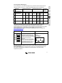
1
D
Appendix
Phoenix Inverter
12/3000
24/3000
48/3000
F
Phoenix MultiPlus
12/2000/100
12/3000/120
24/2000/60
24/3000/70
48/3000/35
NL
Phoenix Multi
12/2000/100
12/3000/120
24/2000/60
24/3000/70
48/3000/35
GB
INSTALLATION MANUAL
INSTALLATIEHANDLEIDING
MANUEL D'INSTALLATION
INSTALLATIONSANLEITUNG
Copyrights © 2006 Victron Energy B.V.
All Rights Reserved
This publication or parts thereof, may not be reproduced in any form, by any method, for any
purpose.
For conditions of use and permission to use this manual for publication in other than the
English language, contact Victron Energy B.V.
VICTRON ENERGY B.V. MAKES NO WARRANTY, EITHER EXPRESSED OR IMPLIED,
INCLUDING BUT NOT LIMITED TO ANY IMPLIED WARRANTIES OF
MERCHANTABILITY OR FITNESS FOR A PARTICULAR PURPOSE, REGARDING
THESE VICTRON ENERGY PRODUCTS AND MAKES SUCH VICTRON ENERGY
PRODUCTS AVAILABLE SOLELY ON AN “AS IS” BASIS.
IN NO EVENT SHALL VICTRON ENERGY B.V. BE LIABLE TO ANYONE FOR SPECIAL,
COLLATERAL, INCIDENTAL, OR CONSEQUENTIAL DAMAGES IN CONNECTION WITH
OR ARISING OUT OF PURCHASE OR USE OF THESE VICTRON ENERGY PRODUCTS.
THE SOLE AND EXCLUSIVE LIABILITY TO VICTRON ENERGY B.V., REGARDLESS OF
THE FORM OF ACTION, SHALL NOT EXCEED THE PURCHASE PRICE OF THE
VICTRON ENERGY PRODUCTS DESCRIBED HERE IN.
Victron Energy B.V. reserves the right to revise and improve its products as it sees fit. This
publication describes the state of this product at the time of its publication and may not
reflect the product at all times in the future.
GB
1. INSTALLATION
This product should be installed by a qualified electrician
NL
1.1 Box Contents
Phoenix Multi, MultiPlus, or Inverter
User manual.
Installation manual.
Bag containing connection items, i.e.:
•
Temperature sensor.
•
Fuse (Mega fuse).
•
Four M8 nuts.
•
Four M8 washers.
•
Four M8 spring washers.
•
Charging current warning sticker.
F
•
•
•
•
D
Appendix
1.2 Location
The product must be installed in a dry and well-ventilated area, as close as possible to the
batteries. There should be a clear space of at least 10 cm around the appliance for cooling.
Excessively high ambient temperature will result in the following:
•
Reduced service life.
•
Reduced charging current.
•
Reduced peak capacity, or shutdown of the inverter.
Never position the appliance directly above the batteries.
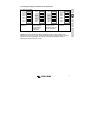
The product is suitable for wall mounting. The back of the enclosure has holes for wall
mounting purposes, see Appendix B.
The appliance can be mounted horizontally as well as vertically; vertical mounting is
preferable. The vertical position offers optimum cooling.
The interior of the product must remain accessible after installation.
Ensure that the AC and DC input cables are fitted with fuses and circuit breakers. Try and
keep the distance between the product and the battery to a minimum in order to minimize
cable voltage losses.
For safety purposes, this product should be installed in a heat-resistant
environment. You should prevent the presence of e.g. chemicals, synthetic
components, curtains or other textiles, etc., in the immediate vicinity.
1
1.3 Requirements
•
•
•
•
•
Philips screwdriver (PH2) for removing the front.
Flat screwdriver (0.6x3.5) for connecting the AC leads.
Insulated box spanner (13 mm) for securing the terminal nuts and the fuse.
Two battery cable including battery terminals and cable ends.
Three-wire cable.
1.4 Connection of Battery cables
In order to fully utilize the full capacity of the product, batteries with sufficient capacity and
battery cables with sufficient cross section should be used. See table.
Recommended
battery capacity (Ah)
Recommended cross
2
section (mm )
0–5m
5 – 10 m
12/2000/100
12/3000/120
24/2000/60
24/3000/70
48/3000/35
200–700
400–1200 100–400
200–700
100–400
50
90
35
70
70
100
90
120
40
70
Remark: Internal resistance is the important factor when working with low capacity batteries.
Please consult your supplier or the relevant sections of our book “electricity on board”,
downloadable from our website.
Procedure
Proceed as follows to connect the battery cables:
Use an insulated box spanner in order to avoid shorting the battery.
Avoid shorting the battery cables.
•
•
•
•
•
•
•
2
Undo the four screws at the front of the enclosure and remove the front panel.
Connect the battery cables: the + (red) on the right and the - (black) on the left, see
Appendix A.
Reverse polarity connection (+ to – and – to +) will cause the “reversed polarity” LED
next to the terminal nuts to light up.
Disconnect the cables and reconnect them correctly if the “reversed polarity" LED is
illuminated.
Tighten the connections after positioning the fastening items supplied with the product.
Position the Mega fuse from the connection bag in position F4 and secure it, using the
fastening items supplied with the product.
Secure the nuts tightly in order to reduce the contact resistance as much as possible.
1.5 Connection of the AC cabling
GB
This is a Safety Class I product (supplied with a protective grounding terminal).
Uninterruptible protective grounding must be provided at the AC input
and/or output terminals and/or chassis grounding point located externally
on the product. See the following instructions:
NL
F
a) The Phoenix Inverter has a free floating AC output. The grounding point
located externally on the product must be used to ground the chassis.
The neutral output wire must be connected to ground to ensure proper
functioning of a GFCI (Ground Fault Circuit Interrupter).
Procedure
Proceed as follows to connect the AC cables:
•
The AC output cable can be connected directly to the terminal block containing the
words "AC-out". The terminal points are indicated clearly. From left to right: “PE”
(earth), “N” (neutral) and “L” (phase).
•
The AC input cable can be connected to the terminal block containing the words “AC–
in”. The terminal points are indicated clearly. “PE” (earth) “N” (neutral) and “L” (phase).
1.6 Optional Connections
A number of optional connections are possible:
1.6.1 Second Battery
The Phoenix Multi/ MultiPlus has a connection for charging a starter battery. For connection
see Appendix A.
3
Appendix
The terminal block can be found on the printed circuit board, see Appendix A. The shore or
mains cable must be connected to the Multi with the aid of a three-wire cable. Use a threewire cable with a flexible core and a cross section of 2.5 or 4 mm²
D
b) Phoenix Multi / MultiPlus: the output neutral wire will automatically be
bonded to the chassis (with the output ground relay, see appendix) when no
external AC source is available (backfeed / safety relay open and product
runnig in inverter mode, see appendix). When an external AC source is
provided, the ground relay opens before closure of the backfeed / safety relay.
Once closed, the backfeed / safety relay ensures that the neutral to ground bond
is provided by the external AC source. This is to ensure proper functioning of a
GFCI to be installed in the AC output of the Multi/MultiPlus.
- In a fixed (for example terrestrial) installation an uninterrupted chassis ground
may be provided by the AC input ground wire.
- In case of a mobile installation (connection to input AC with a shore power
cord), the ground connection is lost when the shore power cord is unplugged. In
this case the chassis of the product or the on - board section of the input ground
wire must be connected to the frame (of the vehicle) or the ground plate or hull
(of a boat).
- Marine applications: due to the potential for galvanic corrosion it is in general
not acceptable to connect the shore side ground to the ground plate or hull of
the boat. The proper and safe solution is to install an isolation transformer.
1.6.2 Voltage Sense (Multi/ MultiPlus)
Two sense wires may be connected to compensate possible battery cable losses during
2
charging. Use wires of at least 0.75mm . For connection see Appendix A.
1.6.3 Temperature Sensor (Multi/ MultiPlus)
The temperature sensor supplied with the product may be used for temperaturecompensated charging (see Appendix A). The sensor is insulated and must be mounted on
the batteries minus pole.
4
GB
1.6.4 Remote Control
The product can be operated remotely in two ways.
•
Use of only an external switch.
•
With a Phoenix Multi Control anel.
For connection of the switch see Appendix A.
Observe the following when using only an external switch:
•
Only functions if the switch on the product is switched to the "on" position.
•
Not to be connected if a remote control panel is connected.
For connection of the remote control panel, see Appendix A.
Observe the following when using a remote control panel:
•
Only functions if the switch on the product is switched to the "on" position.
NL
F
D
1.6.6 Parallel Connection
The product can be connected in parallel using several identical models, see Appendix G.
The batteries must be connected in accordance with Appendix E or F. This requires
interconnecting the products with the aid of a special cable to be supplied by Victron
Energy, in conjunction with a connection diagram.
Parallel connection requires compliance with the following conditions:
•
No more than five units should be connected in parallel.
•
Only identical models should be connected in parallel (exception: for MultiPlus
functionality only the Master needs to be a MultiPlus).
•
Ensure sufficient battery capacity is available.
•
The prescribed cable cross sections (between battery and distribution point) must be
multiplied with the number of appliances to be connected in parallel.
Position the products close to each other but ensure there is adequate clearance for
•
ventilation, min.10 cm.
•
The temperature sensor, voltage sensor and remote control must be connected to the
master.
•
The cables for each appliance must be equal in length (AC and DC).
1.6.7 3-phase operation
The Phoenix Multi/MultiPlus can also be used in a 3-phase system, see Appendix 0. The
batteries must be connected in accordance with Appendix E or F. The following conditions
should be complied with in the case of 3-phase operation:
•
Only identical models should be used.
•
Ensure sufficient battery capacity is available.
Position the products close to each other but ensure there is adequate clearance for
•
ventilation (min. 10 cm)
•
The temperature sensor and voltage sensor should preferably be connected to all
three products.
•
Only a single remote control can be connected, using splitters.
5
Appendix
1.6.5 External Relay (Multi/ MultiPlus)
The maximum current that can be switched through from the AC input to the AC output is 16
A (optional: 30 A). At more than 16 A an external contactor is needed: please consult your
supplier.
2. SETTINGS
•
•
•
•
•
•
Settings may only be changed by a qualified engineer
Carefully read the instructions before changes are made.
When setting the charger, all connections to the battery must be
disconnected from the Phoenix Multi or MultiPlus.
Do not use non-rechargeable batteries.
The Phoenix Multi/ MultiPlus default settings are for charging
Sonnenschein Dryfit A200 gel batteries. For the recommended battery
voltage see section 2.4.
Batteries should be placed in a dry and well-ventilated area during
charging.
2.1 Settings – General
2.1.1 Push buttons and dipswitches
A selected number of settings may be changed with the aid of pushbuttons and dip switches
(see Appendix A).
Dipswitches are used to activate set-up, and to determine the setting to be changed. The
value of this setting can be changed with the aid of the pushbuttons.
The value specified is shown on the LEDs. Sections 2.3 describes how the LEDs can be
read.
2.1.2 VEConfigure software
All settings can be changed with VEConfigure.
VEConfigure can be downloaded from www.victronenergy.com
2.2 Default Settings
System frequency
Inverter Voltage
Charger on/ off
Charger characteristic
Charging Current
Battery Type Presets
Absorption Voltage
Absorption Time/ Maximum Absorption Time
Float Voltage
Repeated Absorption Time
Repeated Absorption Interval
Bulk Protection
AC Waveform Check
Generator/ Shore Current
PowerAssist (MultiPlus only)
3-phase Setting
Master/ slave
50 Hz
230 Vac
on
Adaptive with BatterySafe mode
75% of maximum charging current
type 1 (Exide Gel battery)
14.4/ 28.8/ 57.6 Vdc
4 hours
13.8/ 27.6/ 55.2 Vdc
1 hour
7 days
on
on
16 A (optional: 30 A)
on
off
slave
(To restore the default settings, both pushbuttons should be held down for 3 seconds while
set-up is activated)
6
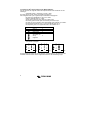
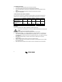
2.3 Changing settings with the push buttons and dipswitches
on
DS-8
DS-7
DS-6
DS-5
DS-4
DS-3
DS-2
DS-1
off
DS-1 and DS-2 are not used and must be switched to Off.
NOTE: The new value is stored by changing the position of one of the switches DS3-DS7.
The new value is NOT stored if set-up is closed without changing the position of one of the
switches DS3-DS7. This offers an escape route if the change is not to be implemented.
7
Appendix
Store the settings by Close set-up by
changing the position switching DS8 to Off
of one of the
switches DS3-DS7
D
Select a setting using
DS3 - DS7 and set
the new value using
the pushbuttons.
DS-8
DS-7
DS-6
DS-5
DS-4
DS-3
DS-2
DS-1
F
Activate set-up with
DS8 switched to On
DS-8
DS-7
DS-6
DS-5
DS-4
DS-3
DS-2
DS-1
NL
DS-8
DS-7
DS-6
DS-5
DS-4
DS-3
DS-2
DS-1
GB
2.3.1 Activate Set-up
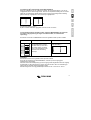
2.3.2 Reading LEDs – setting values (Multi/ MultiPlus)
The value of a setting can be determined on the basis of the following formula:
Value set = setting number * scale + offset
The ‘offset’ and the ‘scale’ are specified for each setting.
The setting number is indicated as follows via the LEDs:
The LEDs are divided into 2 columns of 4 LEDs each.
Each column indicates the numbers 0 - 9.
These columns together indicate 2-digit numbers.
The left column indicates the left-hand digit. The right-hand column shows the
right-hand digit.
The digit in a column can be determined by adding the separate ‘LED values’.
A flashing LED counts as 1 and an illuminated LED as 2.
A special case is 4 flashing LEDs. This signifies a 9.
Symbol
Meaning
LED off
LED flashes
LED lit up
LED value
0
1
2
All LEDs in a
column are
flashing
9
Examples of setting numbers:
0
0
0
0
0
0
2
2
2
6
=6
0
0
2
2
4
1
2
2
2
7
=47
0
0
1
2
3
9
=39
The increments can be smaller than the reading (scale value). In that case, a pushbutton
should be pressed repeatedly before the LED indication changes.
8
B
A
NL
A
GB
2.3.3 Reading LEDs – on-off (Multi/ MultiPlus)
In addition to the facility of setting a value, there is an on- off facility. This allows for
switching on/ off a particular setting, or for activating/ deactivating it. The left-hand column
offers possibility A and the right-hand column offers possibility B in the case of a dual choice
setting.
B
F
=A
=B
D
The default setting is always A.
The definitions for A and B are shown with the value to be set.
Appendix
2.3.4 System Frequency (default: 50 Hz, with 45 – 65 Hz tracking range of AC input
(Multi/MultiPlus only, see note below))
The product can operate at 50Hz as well as at 60Hz.
Set the DS 3-7
DS-8
DS-7
off
DS-6
off
DS-5 on
DS-4
off
DS-3
off
DS-2
DS-1
Specify the frequency
Example
Specify the required frequency.
The default setting is 50Hz.
The left row of LEDs is for 50Hz.
The right row of LEDs is for 60Hz.
Press the buttons until the required
LED indication appears.
Required: frequency is 60Hz.
LED indication =
50Hz
60Hz
Note:
The Phoenix inverter will operate at a fixed frequency of 50Hz or 60Hz.
The Phoenix Multi/MultiPlus will, when no AC input present, likewise operate at a fixed
frequency of 50Hz or 60Hz.
When AC input is present, it will track the input frequency from 45 to 65 Hz. This to be able
to connect to both 50Hz and 60Hz supply.
The tracking range can be reduced to 45 – 55 Hz or 55 – 65 Hz with VEConfigure.
9
2.3.5 Inverter Settings
Inverter Voltage (default: 230 V)
The inverter voltage can be set between 180Vac-245Vac.
Set the DS 3-7
DS-8
DS-7 on
DS-6 on
DS-5
off
DS-4
off
DS-3
off
DS-2
DS-1
Specify the voltage
Example
Specify the required voltage Vq.
Determine the setting number:
scale=1V
offset=180V setting
number=(Vq-180)
Determine the LED indication.
Press the pushbuttons until the
required LED indication is
displayed.
Required: voltage is 225V.
Setting number = 225-180 = 45.
LED indication =
0
0
0
1
2
2
2
2
4
5
Increment size is 1V.
NOTE: for setting the voltage of the Phoenix Inverter a voltage meter is to be used, because
the Phoenix Inverter has only 4 LEDs.
10
GB
2.3.6 Setting the Charger (Multi/ MultiPlus)
NL
When setting the charger, all connections between the battery and the Phoenix Multi must
be disconnected.
Please read our book “electricity on board”
(downloadable from our website www. victronenergy.com) for details and suggestions
about charging batteries.
F
2.3.6.1 Charger On/ Off (default:on)
Set the DS 3-7
Example
Appendix
DS-8
DS-7 on
DS-6
off
DS-5
off
DS-4 on
DS-3
off
DS-2
DS-1
Switch the charger on or off
D
The Phoenix Multi charger can be switched off if required.
The default is on.
Determine whether the charger is to Required: charger is off.
be switched on or off.
LED indication =
The default is On.
On
Off
The left-hand LED column is for On.
The right-hand LED column is for
Off.
Press the pushbuttons until the
required LED indication is
displayed.
2.3.6.2 Preprogrammed Charging Characteristics
The Phoenix Multi/ MultiPlus has 3 pre-programmed charging characteristics:
Fixed Charging Characteristic:
The absorption period is a fixed preset period. Following the absorption mode, the charger
switches to float. In order to “refresh” the battery, the charger periodically switches back to
absorption.
Adaptive Charging Characteristic:
The absorption period depends on the charge delivered during bulk. This is followed by float
phase lasting 24 hours, after which the voltage is reduced by an additional 0.8 V, 1.6 V and
3.2 V resp. for 12 V, 24 V and 48V batteries. (reduced float). As with the Fixed-charging
characteristic, the charger will periodically switch back to absorption.
Adaptive Charging Characteristic with BatterySafe mode (default setting):
If, in order to quickly charge a battery, a high charge current in combination with a high
absorption voltage has been chosen, the Phoenix charger will prevent damage due to
excessive gassing by automatically limiting the rate of voltage increase once the gassing
voltage has been reached
11
Set the DS 3-7
DS-8
DS-7
off
DS-6 on
DS-5 on
DS-4 on
DS-3
off
DS-2
DS-1
Set the charging characteristic
Example
Determine the required charging
characteristic:
1:
Fixed
2:
Adaptive
3:
Adaptive with BatterySafe
mode (default)
Required: charging characteristic
is Fixed.
Setting number = 1.
LED indication =
0
0
0
0
0
0
0
1
Press the pushbuttons until the
required LED indication is
displayed.
0
1
2.3.6.3 Charge Current
The default charging current is 75% of the maximum charging current. This current will be
too high for most applications. For most battery types the optimal charging current is 0.10.2x the battery capacity.
Set the DS 3-7
DS-8
DS-7
off
DS-6 on
DS-5
off
DS-4
off
DS-3
off
DS-2
DS-1
Increment size is 1A.
12
Set the charging current
Example
Determine the required charging
current Iq.
Determine the setting number.
Scale = 2A
Offset = 0A
Setting number = Iq/2
Determine the LED indication.
Press the pushbuttons until the
required LED indication is
displayed.
Battery capacity is 450Ah. The
recommended maximum
charging current is 450*0.2 =
90A.
Setting number = 90/2 = 45.
LED indication =
0
0
0
1
2
2
2
2
4
5
2.3.6.4 Preprogrammed charge voltage (default: Exide Dryfit)
27.6V/
26.4V
27.6V/
26.4V
28.0V/
26.4V
28.0V/
26.4V
55.2V/
52.8V
55.2V/
52.8V
56.0V/
52.8V
56.0V/
52.8V
4 hours
6 hours
5 hours
5 hours
1
The optimal absorption voltage for flat plate lead acid batteries is subject to mechanical and chemical
properties. Batteries with high antimony content can typically be charged with a lower absorption voltage than
batteries with low antimony content. (please refer to our book “Electricity on Board” downloadable from our
website www.victronenergy.com)
The default charge current setting is 75% of the maximum charge current. This current will be too high for
most applications. For most battery types the optimal charge current is 0.1-0.2x the battery capacity.
Set the DS 3-7
DS-8
DS-7 on
DS-6 on
DS-5
off
DS-4
off
DS-3 on
DS-2
DS-1
Set the battery type
Example
Determine the battery type used.
Determine the setting numbers with
the aid of the table.
Press the keys until the required
LED indication is displayed.
NOTE: 0 cannot be selected but will
be displayed if the absorption
voltage, the float voltage or the
absorption time is changed.
Required: the battery type is
Victory:
Setting number = 4.
LED indication =
0
0
0
0
0
2
0
2
0
4
The default setting is the Exide Dryfit A200 battery. Contact your battery supplier for the
correct charge voltages and change the voltage settings if required.
13
Appendix
4
14.4V 28.8V 57.6V 13.8V/
13.2V
15.0V 30.0V 60.0V 13.8V/
13.2V
14.4V 28.8V 57.6V 14.0V/
13.2V
14.8V 29.6V 59.2V 14.0V/
13.2V
Maximum
absorption
time
D
3
User-specified
Exide Dryfit
A200 Gel
Traction
(tubular cell)
Semi Traction 1
(flat plate)
Low antimony 1
Float voltage
F
0
1
(default)
2
Absorption voltage
NL
Battery type
GB
A number of preprogrammed charge voltages tailored to specific battery types simplifies the
process of setting the absorption/ float voltage and maximum absorption time:
2.3.6.5 Absorption Voltage
The absorption voltage can be set at 12-16/ 24-32/ 48-64V. The battery, the T-sense and Vsense must be disconnected during setting.
Set the DS 3-7
DS-8
DS-7
DS-6
DS-5
DS-4
DS-3
DS-2
DS-1
off
off
off
off
off
Set the absorption voltage
Example
Determine the required absorption
voltage Vq.
Determine the setting number.
Scale = 0.1V
Offset = 12/24V
Setting number = (Vq24)/0,1
Determine the LED indication.
Press the pushbuttons until the
required LED indication is
displayed.
Required: absorption voltage is
28.5V.
Setting number= (28.5-24)/0.1 =
45.
LED indication =
0
0
0
1
2
2
2
2
4
5
Increment size is 0.05 V.
2.3.6.6 Absorption Time/ Maximum Absorption Time (default: 4 hours)
This setting defines the absorption period in the case of the fixed charging characteristic
and the maximum absorption time in the case of the adaptive charging characteristic.
The (maximum) absorption time can be set from 1 to 8 hours.
Set the DS 3-7
Set the (maximum) absorption time
Example
DS-8
DS-7 on
DS-6
off
DS-5 on
DS-4 on
DS-3
off
DS-2
DS-1
Determine the required (maximum)
absorption time Tq.
Determine the setting number.
Scale = 1 hour
Offset = 0
Setting number = Tq
Determine the LED indication.
Press the pushbuttons until the
required LED indication is
displayed.
Required: (maximum) absorption
time is 4 hours.
Setting number = 4.
LED indication =
0
0
0
0
0
2
0
2
0
4
Increments are 1 hour.
14
2.3.6.7 Float Voltage
GB
The float voltage can be set at 12-16/ 24-32/ 48-64V. Battery, the T-sense and V-sense
must be disconnected during setting.
Determine the required float voltage
Vq.
Determine the setting number.
Scale = 0.1V
Minimum = 12/24V
Setting number = (Vq24)/0,1
Determine the LED indication.
Press the pushbuttons until the
required LED indication is
displayed.
Required: float voltage is 28.5V.
Setting number= (28.5-24)/0.1 =
45.
LED indication =
0
0
0
1
2
2
2
2
4
5
Increment size is 0.05 V.
2.3.6.8 Repeated Absorption
After each charging cycle, the charger will be switched back to the high charging current
after a pre-set time, following the float phase. This switch back action is called "repeated
absorption mode", see Appendix C.
Repeated Absorption Time (default: 1 hour)
The repeated absorption time can be set at 1 – 72 quarters of an hour.
Set the DS 3-7
DS-8
DS-7 on
DS-6 on
DS-5 on
DS-4
off
DS-3
off
DS-2
DS-1
Set the repeated absorption time
Example
Determine the required Repeated
absorption time Tq in quarters of an
hour.
Determine the setting number.
Scale = 1 quarter of an hour
Offset = 0
Setting number = Tq
Determine the LED indication.
Press the pushbuttons until the
required LED indication is
displayed.
Required: Repeated absorption
time is 1 hour.
Setting number = 1 hour = 4
quarters of an hour
LED indication =
0
0
0
0
0
2
0
2
0
4
Increment size is a quarter of an hour.
15
Appendix
Example
D
Set the float voltage
F
DS-8
DS-7 on
DS-6
off
DS-5
off
DS-4
off
DS-3
off
DS-2
DS-1
NL
Set the DS 3-7
Repeated Absorption Interval (default: 7 days)
The repeated absorption interval, can be set at 1 – 45 days.
Set the DS 3-7
DS-8
DS-7
off
DS-6
off
DS-5
off
DS-4 on
DS-3
off
DS-2
DS-1
Set the repeated absorption interval
Example
Determine the required reduced
float time Tq.
Determine the setting number.
Scale = 1 day
Offset = 0
Setting number = Tq
Determine the LED indication.
Press the pushbuttons until the
required LED indication is
displayed.
Required: reduced float time is 1
week.
Setting number = 7.
LED indication =
0
1
0
2
0
2
0
2
0
7
Increments are 1 day.
16
2.3.7 Special Settings (default: on)
GB
Example
Determine whether the bulk cut out Required: bulk cut out is off.
should be switched on or off.
LED indication =
The default is On.
On
Off
The left-hand LED column is for On.
The right-hand LED column is for
Off.
Press the pushbuttons until the
required LED indication is
displayed.
D
Appendix
DS-8
DS-7
off
DS-6 on
DS-5
off
DS-4 on
DS-3
off
DS-2
DS-1
Switch the bulk cut-out to on or off
F
Set the DS 3-7
NL
2.3.7.1 Bulk Protection On/ Off
If the charger has not reached the absorption voltage after 10 hours' charging in the bulk
phase, the battery may be defective. In order to prevent further damage, the charger will
automatically cut out after 10 hours' bulk. The “bulk” LED will start to flash.
This safety cut out can be switched off.
2.3.7.2 AC Waveform Check (default: on)
The Phoenix Multi checks if the mains voltage has not only the correct voltage, but also the
correct shape. When the Phoenix Multi does not function properly on a generator this
function can be disabled.
Set the DS 3-7
DS-8
DS-7
off
DS-6 on
DS-5
off
DS-4
off
DS-3 on
DS-2
DS-1
Switch the Mains Voltage Check to
on or off
Example
Determine whether the Mains
Required: Mains Waveform
Waveform Check should be
Check is off.
switched on or off.
LED indication =
The default is On.
On
Off
The left-hand LED column is for On.
The right-hand LED column is for
Off.
Press the pushbuttons until the
required LED indication is
displayed.
17
2.3.7.3 PowerControl – Dealing with limited generator or shore side power
The Multi is a very powerful battery charger. It will therefore draw a lot of current from the
generator or shore side supply (nearly 10 A per Multi at 230 VAC). With the Phoenix Multi
Control Panel a maximum generator or shore current can be set. The Multi will then take
account of other AC loads and use whatever is extra for charging, thus preventing the
generator or shore supply from being overloaded.
It is also possible to set the max. generator/ shore current internally.
The generator/ shore current can be set at 2 - 16A (optional 4 – 30A).
Set the DS 3-7
DS-8
DS-7
off
DS-6 on
DS-5 on
DS-4
off
DS-3
off
DS-2
DS-1
Set the shore current
Example
Determine the required shore
current limitation Iq.
Determine the setting number.
Scale = 1A
Offset = 0
Setting number = (Iq)/1
Determine the LED indication.
Press the pushbuttons until the
required LED indication is
displayed.
Required: shore current
limitation is 16A.
Setting number = 16.
LED indication =
0
0
0
2
0
2
2
1
Increment size is 1A.
The remote control panel setting overrides the internal setting.
18
1
6
D
Appendix
Example
F
DS-8
DS-7 on
DS-6
off
DS-5 on
DS-4
off
DS-3
off
DS-2
DS-1
Switch PowerAssist on or off
NL
Set the DS 3-7
GB
2.3.7.4 PowerAssist – Boosting the capacity of shore or generator power (default: on)
The feature that distinguishes the Phoenix MultiPlus from the standard Multi is PowerAssist.
This feature takes the principle of PowerControl to a further dimension allowing the
MultiPlus to supplement the capacity of the alternative source. Where peak power is so
often required only for a limited period, it is possible to reduce the size of generator needed
or conversely enable more to be achieved from the typically limited shore connection. When
the load reduces, the spare power is used to recharge the battery.
Note 1: minimum shore current 2 A or generator capacity 2,5 kW required per MultiPlus.
Note 2: Some modern AC generators use a static inverter to generate the AC output. Some
of these generators also reduce rpm when operating with reduced load. By enabling the
Dynamic Current Limit function (VEConfigure) the MultiPlus can be used to assist the
generator when suddenly a high load is connected.
Determine whether PowerAssist
Required: PowerAssist is on.
support should be on or off.
LED indication =
The default is Off.
Off
On
The left-hand LED column is for Off.
The right-hand LED column is for
On.
Press the pushbuttons until the
required LED indication is
displayed.
19
2.3.7.5 3-phase Setting (default: off)
Three identical units can t be interconnected for a 3-phase system, in accordance with
Appendix 0. The batteries must be connected in accordance with Appendix E or F. A
number of settings are then required for each unit.
Firstly, all units must be set for 3-phase operation.
Set the DS 3-7
DS-8
DS-7 on
DS-6 on
DS-5
off
DS-4 on
DS-3
off
DS-2
DS-1
Switch 3-phase operation on or off
Example
Determine whether 3-phase
Required: 3-phase operation is
operation should be on or off.
on.
The default is Off.
LED indication =
The left-hand LED column is for Off.
Off
On
The right-hand LED column is for
On.
Press the pushbuttons until the
required LED indication is
displayed.
One of the three units must be set as the "master" following this setting.. No further settings
are required for the other units.
Set the DS 3-7
DS-8
DS-7
off
DS-6
off
DS-5 on
DS-4 on
DS-3
off
DS-2
DS-1
20
Set the master/ slave
Example
Determine master or slave.
The default is slave.
The left-hand LED column is for
slave.
The right-hand LED column is for
the master.
Press the pushbuttons until the
required LED indication is
displayed.
Required: this unit is the master.
LED indication =
slave
master
2.4 Settings that can be changed with VEConfigure
Appendix
21
D
The Phoenix Multi does not require specific maintenance. Annual checking of all
connections and eventually removal of dust suffices. Protect the product from humidity and
oil fumes and keep it clean.
F
2.5 Maintenance
NL
The following settings can be changed with VEConfigure only (see VEConfigure for a
complete list):
- Ground relay (default: on). When running on inverter the output neutral is connected to
the output ground wire and therefore also the chassis. This is to ensure proper functioning
of a GFCI (Ground Fault Circuit Interrupter), to be installed on the AC output of the
MultiPlus. In an isolated system the ground relay should be disabled. Proper isolation of
both phase and neutral from ground should then be monitored with an isolation watch
system.
- Dynamic current limit (default: off). Some modern AC generators use a static inverter to
generate the AC output. Some of these generators also reduce rpm when operating with
reduced load. By enabling the Dynamic Current Limit function (VEConfigure) the MultiPlus
can be used to assist the generator when suddenly a high load is connected.
- Alarm Relay / Virtual Switch (default: disabled)
A programmable relay is available in both the Phoenix Inverter and Multi/MultiPlus. This
relay can be used for remote alarm and other purposes (a. o. generator start signal). The
relay can be programmed with VEConfigure.
- AC input frequency tracking range: see section 2.3.4.
GB
All settings discussed in the previous paragraph can also, and much more conveniently, be
changed with VEConfigure
3. TROUBLE SHOOTING TABLE
Proceed as follows for quick detection of common faults.
DC loads must be disconnected from the batteries and the AC loads must be disconnected
from the inverter before the inverter and/ or battery charger is tested.
Consult your Victron Energy dealer if the fault cannot be resolved.
Problem
Cause
Solution
The inverter fails
to operate when
switched on.
The “low battery”
LED flashes.
The “low battery”
LED on.
The “overload”
LED flashes.
The “overload”
LED on.
The “temperature”
LED flashes or is
on.
The “low battery”
and “overload”
LEDs flash
alternately.
The “low battery”
and “overload”
LEDs flash
simultaneously.
The “low battery”
and “overload”
LEDs are on.
The battery voltage is too high
or too low.
Ensure that the battery voltage
is within the correct value.
The battery voltage is low.
Charge the battery or check the
battery connections.
Charge the battery or check the
battery connections.
reduce the load.
One LED alarm is
on and the
second LED is
flashing
The inverter did cut out as a
result of the illuminated alarm
indication (LED). The flashing
LED indicates that the inverter
also nearly did cut out as a
result of the relevant alarm.
22
The inverter cuts out because
the battery voltage is too low.
The load on the inverter is
higher than the nominal load.
The inverter cuts out due to
excessive load.
The ambient temperature is too
high, or the load is excessive.
Low battery voltage and
excessive load.
Voltage ripple on the DC input
exceeds 1.25Vrms.
The inverter cuts out as a result
of excessive voltage ripple on
the DC input.
reduce the load.
Place the inverter in a cool and
well-ventilated room, or reduce
the load.
Charge the batteries, reduce
the load or install batteries with
a higher capacity. Use shorter
and/ or thicker battery cables.
Check the battery cables and
terminals.
Check the battery capacity;
increase if necessary.
Install batteries with a higher
capacity. Use shorter and/ or
thicker battery cables and reset
the inverter (switch off and on
again).
Check the table for the
appropriate course of action.
Problem
Ensure that the mains voltage is
between 185 Vac and 265 Vac,
and that the frequency matches
the setting.
The thermal circuit breaker has
tripped.
Reset the 16 A thermal circuit
breaker.
The float voltage has been set to
an incorrect value.
The DC fuse is defective.
The absorption voltage has been
set to an incorrect value.
The float voltage has been set to
an incorrect value.
A defective battery.
Adjust the float voltage to the
correct value.
Replace the DC fuse.
Adjust the absorption voltage to
the correct value.
Adjust the float voltage to the
correct value.
Replace the battery.
The battery is too small.
Reduce the charging current or
use a battery with a higher
capacity.
Connect a temperature sensor.
The battery is too hot.
Battery charge
current drops to 0
when the
absorption voltage
is reached
Alt. 1: Battery over temperature
(> 50°C)
Alt 2: Battery temperature sensor
faulty
Appendix
Adjust the absorption voltage to
the correct value.
D
The absorption voltage has been
set to an incorrect value.
F
A defective battery connection.
Set the charging current at
between 0.1 and 0.2x battery
capacity.
Check the battery terminals.
NL
The mains voltage or mains
frequency is out of range.
The battery is not
Incorrect charging current.
being charged fully.
The battery is
overcharged.
Solution
GB
The charger is not
functioning
Cause
- Allow battery to cool down
- Place battery in a cool
environment
- Check for shorted cells
Unplug battery temperature
sensor from the Multi.
Reset the Multi by switching it
off, then wait for 4 seconds and
switch it on again
If the Multi now charges
normally, the battery
temperature sensor is faulty and
needs to be replaced
23
24
Phoenix
Multi/MultiPlus
12/3000/120
24/2000/60
24/3000/70
48/3000/35
9,5-16,1
9,5-16,1
19,0-32,2
19,0-32,2
38,0-64,4
NL
12/2000/100
INVERTER
F
230 ± 2%
50 ± 0,1%
D
2000
3000
2000
3000
3000
1800
2500
1800
2500
2500
1400
1600
1500
2000
2000
4000
4500
4000
6000
6000
93
93
94
94
95
6
6
6
6
10
Appendix
Input voltage range
(V DC)
Output voltage
(V AC)
Frequency
(Hz) (1)
Cont. output power at
25 °C (VA) (5)
Cont. output power at
25 °C (W)
Cont. output power at
40 °C (W)
Peak power
(W)
Maximum efficiency
(%)
Zero-load (economy)
power (W)
CHARGER
Input voltage range
(V AC)
Input frequency
(Hz)
187-265
45 - 55
Power factor
Charge voltage
'absorption' (V DC)
Charge voltage 'float'
(V DC)
Storage mode
(V DC)
Charge current house
batt. (A) (4)
Charge current starter
batt. (A)
Battery capacity
(Ah)
Battery temperature
sensor
GB
4. TECHNICAL DATA
1
14,4
14,4
28,8
28,8
57,6
13,8
13,8
27,6
27,6
55,2
13,2
13,2
26,4
26,4
52,8
100
120
60
70
35
4
4
4
4
4
300-1000
400-1200
150-600
200-700
100-400
√
√
√
√
√
25
Phoenix
Multi/MultiPlus
12/2000/100
12/3000/120
24/2000/60
24/3000/70
48/3000/35
GENERAL
Multi purpose relay
√ (6)
Forced cooling
√
Protection (2)
a-h
Operating temp. range
-20 to +50°C
Humidity
(non condensing)
max 95%
ENCLOSURE
Material & Colour
aluminium (blue RAL 5012)
Battery-connection
M8 studs
230 V AC-connection
screw-clamp 2,5 mm²
Protection category
Weight
(kg)
Dimensions
(hxwxd in mm)
IP 21
18
18
18
18
18
362x258x218
STANDARDS
Safety
EN 60335-1, EN 60335-2-29
Emission
EN 50081-1, EN55014, EN 61000-3-2, EN 61000-3-3
Immunity
EN 55014-2
Automotive Directive
95/54/EC
1) Can be adjusted to 60 Hz
2) Protection
a. Output short circuit
b. Overload
c. Battery voltage too high
d. Battery voltage too low
e, Battery reverse polarity detection
f. 230 V AC on inverter output
g. Input voltage ripple too high
h. Temperature too high
3) Not available in MultiPlus version
4) At 25 °C ambient
5) Non linear load, crest factor 3:1
6) Multipurpose relay which can be set for general alarm, DC under voltage or genset start signal function
26
n. a.
1. INSTALLATIE
GB
Dit product mag alleen door een gekwalificeerde elektrotechnicus worden
geïnstalleerd.
NL
1.1 Inhoud van de doos
F
De doos van de Phoenix Multi bevat de volgende zaken:
•
Phoenix Multi.
•
Gebruikershandleiding.
•
Installatiehandleiding.
•
Zakje met aansluitmateriaal met daarin:
•
Temperatuursensor.
•
Zekering. (Mega fuse)
•
Vier moeren M8.
•
Vier sluitringen M8.
•
Vier veerringen M8.
•
Waarschuwingssticker laadstroom.
D
Appendix
1.2 Locatie
De Phoenix Multi dient in een droge, goed geventileerde ruimte te worden geïnstalleerd zo
dicht mogelijk bij de accu’s. Rondom het apparaat dient een ruimte van tenminste 50mm te
worden vrijgehouden voor koeling.
Een te hoge omgevingstemperatuur heeft de volgende consequenties:
•
Kortere levensduur.
•
Lagere laadstroom.
•
Lager piek vermogen of geheel afschakelen van de omvormer.
Plaats het apparaat nooit direct boven de accu’s.
De Phoenix Multi is geschikt voor wandmontage. Voor de montage zijn aan de achterzijde
van de behuizing gaten aangebracht, zie appendix B.
Het apparaat kan zowel horizontaal als verticaal gemonteerd worden maar verticaal
monteren is de beste montage. In deze positie is de koeling namelijk optimaal.
De binnenzijde van het apparaat dient ook na installatie goed bereikbaar te
blijven.
Zorg ervoor dat de aansluitkabels zijn voorzien van zekeringen en stroomonderbrekers.
Houd de afstand tussen de Phoenix Multi en de accu zo kort mogelijk om het
spanningsverlies over de kabels tot een minimum te beperken.
Installeer het product in een hittebestendige omgeving.
Voorkom daarom de aanwezigheid van bijvoorbeeld chemicaliën, kunststof
onderdelen, gordijnen of ander textiel, etc. in de directe omgeving.
1
1.3 Benodigdheden
•
•
•
•
•
Een kruiskop schroevendraaier (PH 2) voor het verwijderen van het front.
Een platte schroevendraaier (0,6x3,5) voor het aansluiten van de AC kabels.
Een geïsoleerde pijpsleutel (13 mm) voor het vastdraaien van de aansluitbouten en de
zekering.
Twee accukabels (maximum lengte 6 meter) inclusief accuklemmen en kabelogen.
Drie-aderige kabel.
1.4 Aansluiten accukabels
Om de capaciteit van de Phoenix Multi volledig te kunnen benutten dient uitsluitend gebruik
te worden gemaakt van accu’s met voldoende capaciteit en van accukabels met de juiste
dikte. Zie tabel.
Aanbevolen
accucapaciteit (Ah)
Aanbevolen
2
kabeldikte (mm )
0–5m
5 – 10 m
12/2000/100
12/3000/120
24/2000/60
24/3000/70
48/3000/35
300–1000
400–1200 150–600
200–700
100–400
50
90
35
70
70
100
90
120
40
70
Procedure
Ga bij het aansluiten van de accukabels als volgt te werk:
•
•
•
•
•
•
•
2
Om het gevaar van kortsluiting van de accu te voorkomen, dient u een
geïsoleerde pijpsleutel te gebruiken.
Voorkom kortsluiting van de accukabels.
Draai de vier schroeven aan de voorzijde van de behuizing los en verwijder het front.
Sluit de accukabels aan: de + (rood) aan de rechterzijde en de - (zwart) aan de
linkerzijde, zie appendix A.
Indien de accukabels van de Phoenix Multi zijn verwisseld
(+ op – en – op +), zal de “reversed polarity” LED, die zich naast de aansluitbouten
bevindt, branden.
Als de “reversed polarity LED” brandt, ontkoppel de kabels en sluit ze op de juiste
manier aan.
Draai de aansluitingen vast na het plaatsen van het bijgeleverde
bevestigingsmateriaal.
Plaats de mega fuse uit het aansluitzakje op positie F4 en draai deze vast na het
plaatsen van het bijgeleverde bevestigingsmateriaal.
Draai de moeren stevig aan om overgangsweerstanden zo laag mogelijk te maken.
1.5 Aansluiten AC kabels
GB
Dit is een product uit veiligheidsklasse I. (dat wordt geleverd met een aardklem
ter beveiliging) De in - en/ of uitgangsklemmen en/of het aard punt aan de
buitenkant van het product moeten zijn voorzien van een
ononderbreekbare aarding ter beveiliging. Zie hiervoor de volgende
instructies:
NL
Procedure
Ga voor het aansluiten van de AC kabels als volgt te werk:
•
De AC apparatuur kan direct op het klemmenblok met de tekst “AC–out” worden
aangesloten met behulp van een drie-aderige kabel. De aansluitpunten zijn duidelijk
gecodeerd. Van links naar rechts: “PE” (aarde), “N” (nulleider) en “L” (fase)
•
De AC netspanning kan worden aangesloten op het klemmenblok met de tekst “AC–
in”. De aansluitpunten zijn duidelijk gecodeerd. “PE” (aarde) “N” (nulleider) en “L”
(fase)
1.6 Aansluitopties
Naast de standaardaansluitingen kunnen er nog een aantal opties worden aangesloten.
1.6.1 Startaccu
De Phoenix Multi heeft een aansluiting voor het laden van een startaccu. Zie voor het
aansluiten appendix A.
3
Appendix
Het klemmenblok bevindt zich op de printplaat, zie appendix A. De wal- of netaansluiting
dient met behulp van een drie-aderige kabel op de Multi te worden aangesloten. Maak
gebruik van een drie-aderige kabel met een soepele kern en een doorsnede van 2,5 of 4
mm². (type H05RN-F)
D
b) De Phoenix Multi / MultiPlus is voorzien van een aard relais (zie appendix) dat
de N uitgang automatisch met de behuizing verbint wanneer geen externe
wisselspanning voeding beschikbaar is. Wanneer een externe
wisselspanning voeding wordt aangeboden zal het aard relais openen voordat
het ingang veiligheids relais sluit (zie appendix). Dit is om goede werking van
een op de uitgang aangesloten aardlekschakelaar te verzekeren.
- In een vaste installatie kan een ononderbreekbare aarding verzekerd worden
met de aard draad van de wisselspanning ingang. Zoniet, dan moet de
behuizing geaard worden.
- In een mobiele installatie (bijvoorbeeld met walstroom stekker) zal
onderbreking van de walaansluiting tegelijk ook de aard verbinding verbreken. In
dat geval moet de behuizing verbonden worden met het chassis (van het
voertuig) of met de romp of aardplaat (van de boot).
- Op boten is de hierboven beschreven verbinding met de aarde van de
walaansluiting i. h. a. niet aan te bevelen i. v. m. galvanische corrosie.
De oplossing hiervoor is plaatsing van een isolatie transformator.
F
a) De Phoenix Inverter heeft een vrij zwevende uitgangspanning. De behuizing
moet geaard worden met het aard punt aan de buitenkant van het product. De N
uitgang moet geaard worden om verzekerd te zijn van de goede werking van
een aardlek schakelaar.
1.6.2 Voltage sense (Multi/ MultiPlus)
Voor het compenseren van eventuele kabel verliezen tijdens het laden kunnen er twee
2
sense draden worden aangesloten. Gebruik tenminste 0,75mm draad. Zie voor het
aansluiten appendix A.
1.6.3 Temperatuursensor (Multi/ MultiPlus)
Voor het temperatuur gecompenseerd laden kan de bijgeleverde temperatuursensor worden
aangesloten. (zie appendix A) De sensor is geïsoleerd en moet op de min pool van de accu
worden gemonteerd.
4
GB
1.6.4 Afstandsbediening
De Phoenix Multi is op twee manieren op afstand te bedienen.
•
Met alleen een externe schakelaar.
•
Met een afstandsbedieningspaneel.
Voor het aansluiten van de schakelaar zie appendix A.
Indien gebruik wordt gemaakt van alleen een externe schakelaar dient u met het volgende
rekening te houden:
•
Werkt alleen als de schakelaar van de Phoenix Multi op “on” staat.
•
Mag niet worden aangesloten als er een afstandsbedieningspaneel is aangesloten.
Voor het aansluiten van een afstandsbedieningspaneel zie appendix A.
Indien gebruik wordt gemaakt van een afstandsbedieningspaneel dient u met het volgende
rekening te houden:
•
Werkt alleen als de schakelaar van de Phoenix Multi op “on” staat.
NL
F
D
1.6.6 Parallel schakelen
De Phoenix Multi is parallel te schakelen met meerdere identieke apparaten, zie appendix
G. De accu’s moeten aangesloten worden volgens appendix E of F. Het parallel schakelen
biedt de mogelijkheid eenvoudig de vermogenscapaciteit te verhogen. Hiervoor wordt een
verbinding tussen de apparaten gemaakt met behulp van een speciaal door Victron Energy
te leveren kabel met aansluitschema.
Bij parallel schakelen moet aan de volgende voorwaarden voldaan worden:
•
Schakel niet meer dan vijf apparaten parallel.
•
Schakel alleen identieke apparaten parallel.(uitzondering: voor MultiPlus functionaliteit
hoeft alleen de Master een MultiPlus te zijn)
•
Zorg voor voldoende accucapaciteit.
•
De voorgeschreven kabeldiktes (tussen accu en distributiepunt) moeten
vermenigvuldigd worden met het aantal parallel te schakelen apparaten.
Plaats de Multi’s dicht bij elkaar, maar zorg voor minimaal 10 cm ventilatieruimte.
•
•
Temperatuursensor, voltage sense en afstandsbediening dienen op de master
aangesloten te worden.
•
De kabels per apparaat dienen even lang te zijn. (AC en DC)
1.6.7 3-Fase schakelen
De Phoenix MultiPlus kan ook gebruikt worden in een 3-fase net, zie appendix 0. De accu’s
moeten aangesloten worden volgens appendix E of F. Bij 3-fase schakelen moet aan de
volgende voorwaarden voldaan worden:
•
Schakel alleen identieke apparaten in 3-fase.
•
Zorg voor voldoende accucapaciteit.
Plaats de MultiPlus apparaten dicht bij elkaar, maar zorg voor voldoende
•
ventilatieruimte.
•
Temperatuursensor en voltage sense moeten bij voorkeur op alle drie apparaten
aangesloten worden.
•
Er kan één afstandsbediening aangesloten worden met behulp van splitters.
5
Appendix
1.6.5 Extern relais (Multi/ MultiPlus)
De maximale stroom die doorgeschakeld kan worden is 16 A (optioneel 30A)
Indien het gewenst is om meer dan 16 Ampère door te schakelen kan een extern relais
toegepast worden. Neem hiervoor contact op met uw leverancier.
2. INSTELLINGEN
•
•
•
•
•
•
Het wijzigen van de instellingen mag alleen worden uitgevoerd door een
gekwalificeerde elektrotechnicus.
Lees voor het wijzigen goed de instructies.
Tijdens het instellen van de lader moeten alle verbindingen naar de accu
losgekoppeld zijn van de Phoenix Multi.
Geen niet-oplaadbare accu’s gebruiken.
Deze Phoenix Multi heeft een fabrieksinstelling voor het laden van Exide
Dryfit A200 gel accu’s. Zie voor de aanbevolen accucapaciteit paragraaf 0.
Tijdens het laden moeten accu’s in een droge, goed geventileerde ruimte
staan.
2.1 Instelling algemeen
2.1.1 Instellen met druktoetsen en dipswitches
Een aantal instellingen kan gewijzigd worden door middel van druktoetsen en dipswitches.
(zie appendix A)
Met de dipswitches activeert u de set-up en bepaalt u welke instelling gewijzigd wordt. Met
de druktoetsen kunt u de waarde van deze instelling wijzigen.
Via de LED’s kunt u de ingestelde waarde aflezen. Paragraaf 0 en 0 beschrijven hoe de
LED’s afgelezen worden.
2.1.2 Instellingen wijzigen met VEConfigure software
Alle instellingen kunnen gewijzigd worden met VEConfigure software
U kunt de VEConfigure software downloaden van www.victronenergy.com
2.2 Standaard (fabrieks-) instellingen
Systeem frequentie
50 Hz
Omvormer Voltage
230 Vac
Lader on/ off
on
Lader karakteristieken
Adaptive met BatterySafe mode
Laderstroom
75% van de maximum laadstroom
Accu Type Presets
type 1
Absorption Voltage
14.4/ 28.8/ 57.6 Vdc
Absorption Tijd/ Maximum Absorption Tijd
4 uur
Float Voltage
13.8/ 27.6/ 55.2 Vdc
Herhaalde Absorption Tijd
1 uur
Herhaalde Absorption Interval
7 dagen
Bulk Beveiliging
on
Sinusvorm Check
on
Generator/ Walstroom
16 A (optioneel: 30A)
PowerAssist (alleen MultiPlus)
on
3-phase Instellingen
off
Master/ Slave
Slave
(Om alle fabrieksinstellingen te herstellen moeten beide druktoetsen 3 seconden ingedrukt
worden terwijl de set-up geactiveerd is)
6
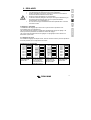
2.3 Instellingen wijzigen met druktoetsen en dipswitches
on
DS-8
DS-7
DS-6
DS-5
DS-4
DS-3
DS-2
DS-1
off
D
Sla de instellingen op Set-up verlaten met
door één van de
DS8 op Off
schakelaars DS3 t/m
DS7 te veranderen
Appendix
Instelling kiezen met
DS3 t/m DS7 en
nieuwe waarde
instellen met
druktoetsen
DS-8
DS-7
DS-6
DS-5
DS-4
DS-3
DS-2
DS-1
F
Set-up activeren met
DS8 op On
DS-8
DS-7
DS-6
DS-5
DS-4
DS-3
DS-2
DS-1
NL
DS-8
DS-7
DS-6
DS-5
DS-4
DS-3
DS-2
DS-1
GB
2.3.1 Set-up activeren
DS-1 en DS-2 zijn gereserveerd en dienen op Off gezet te worden.
LET OP: De nieuwe waarde wordt alleen opgeslagen als een andere instelling wordt
geselecteerd. Als de set-up wordt verlaten zonder een andere instelling te kiezen, wordt de
nieuwe waarde NIET opgeslagen. Dit biedt een ontsnappingsmogelijkheid indien de
wijziging niet doorgevoerd moet worden.
7
2.3.2 Aflezing LED’s meervoudige keuze (Multi/ MultiPlus)
Aan de hand van de volgende formule kan bepaald worden wat de waarde van een
instelling is:
Ingestelde waarde = instelgetal * schaal + offset
De ‘offset’ en de ‘schaal’ worden per instelling opgegeven.
Het instelgetal wordt op de volgende wijze via de LED’s weergegeven:
De LED's zijn opgedeeld in 2 rijen van 4 LED's.
Iedere rij geeft de cijfers 0 - 9 weer.
Samen geven deze rijen een getal met 2 cijfers weer.
De linkerrij geeft het linker cijfer. De rechterrij het rechter cijfer.
Het cijfer van een rij bepaalt u door afzonderlijke ‘LED waardes’ op te tellen.
Een knipperende LED telt voor 1 en een brandende LED voor 2.
Een bijzonder geval is 4 knipperende LED’s. Dit betekent een 9.
Symbool
Betekenis
LED uit
LED knippert
LED brandt
LED waarde
0
1
2
Alle LED’s van
een rij
knipperen
9
Voorbeelden instelgetal:
0
0
0
0
0
0
2
2
2
6
=6
0
0
2
2
4
1
2
2
2
7
=47
0
0
1
2
3
9
=39
De stapgrootte kan kleiner zijn dan de aflezing. (schaalwaarde) In dat geval moet een
druktoets meerdere malen worden ingedrukt voordat de LED aanduiding wijzigt.
8
B
A
NL
A
GB
2.3.3 Aflezing LED’s tweevoudige keuze (Multi/ MultiPlus)
Naast de mogelijkheid om een waarde in te stellen, de meervoudige keuze, is er ook de
mogelijkheid van een tweevoudige keuze. Hier kan een bepaalde instelling aan/ uit worden
gezet dan wel geactiveerd/ gedeactiveerd worden. Bij een tweevoudige keuze instelling
geeft de linker rij mogelijkheid A en de rechter rij mogelijkheid B.
B
F
=B
D
=A
De fabrieksinstelling is altijd A.
Bij de in te stellen waarde is opgegeven waar de A en B voor staan.
Appendix
2.3.4 Systeemfrequentie (standaard: 50Hz, waarbij de Multi/MultiPlus de frequentie
van de AC ingangsspanning zal volgen van 45Hz tot 65Hz, zie onderstaande
opmerking)
De Phoenix omvormer and Multi/MultiPlus kunnen ingesteld worden op 50Hz of 60Hz.
Stel de DS 3-7 in
DS-8
DS-7
off
DS-6
off
DS-5 on
DS-4
off
DS-3
off
DS-2
DS-1
Stel de frequentie in
Voorbeeld
Bepaal de gewenste frequentie.
De fabrieksinstelling is 50Hz.
De linker LED rij is voor 50Hz.
De rechter LED rij voor 60Hz.
Druk op de druktoetsen tot de
gewenste LED aanduiding
verschijnt.
Gewenst: frequentie is 60Hz.
LED aanduiding =
50Hz
60Hz
Opmerking:
De Phoenix omvomer kan ingesteld worden op 50Hz of 60Hz.
Dit is ook van toepassing op de Multi/MultiPlus, wanneer op de AC ingang geen
wisselspanning aanwezig is.
Wanneer echter wel wisselspanning op de AC ingang wordt aangeboden zal de AC uitgang
de frequentie van de ingangspanning volgen van 45Hz tot 65Hz. Dit is om aansluiting op
50Hz zowel als op 60Hz voeding mogelijk te maken.
Met VEConfigure kan het volg gebied beperkt worden tot 45 – 55 Hz of 55 – 65 Hz.
9
2.3.5 Instelling omvormer
Omvormerspanning (standaard: 230V)
De omvormerspanning kan ingesteld worden van 180Vac-245Vac.
Stel de DS 3-7 in
DS-8
DS-7 on
DS-6 on
DS-5
off
DS-4
off
DS-3
off
DS-2
DS-1
Stel de spanning in
Voorbeeld
Bepaal de gewenste spanning Vq.
Bepaal het instelgetal:
schaal=1V
offset=180V
instelgetal=(Vq-180)
Bepaal de LED aanduiding.
Druk op de druktoetsen tot de
gewenste LED aanduiding
verschijnt.
Gewenst: spanning is 225V.
Instelgetal = 225-180 = 45.
LED aanduiding =
0
0
0
1
2
2
2
2
4
5
De stapgrootte is 1V.
LET OP: Voor het instellen van de spanning op de Phoenix inverter moet er gebruik
worden gemaakt van een voltmeter, omdat de Phoenix Inverter maar 4 LED’s heeft.
10
2.3.6 Instelling lader (Multi/ MultiPlus)
GB
Tijdens het instellen van de lader dienen alle verbindingen tussen de accu en de Phoenix
Multi losgekoppeld worden.
2.3.6.1 Lader aan/ uit (standaard: aan)
NL
De lader van de Phoenix Multi kan desgewenst ook uitgeschakeld worden.
De standaard instelling is aan.
Bepaal of de lader aan of
uitgeschakeld moet zijn.
De fabrieksinstelling is Aan.
De linker LED rij is voor Aan.
De rechter LED rij voor Uit.
Druk op de druktoetsen tot de
gewenste LED aanduiding
verschijnt.
Gewenst: lader is uit.
LED aanduiding =
Aan
Uit
Appendix
Voorbeeld
D
DS-8
DS-7 on
DS-6
off
DS-5
off
DS-4 on
DS-3
off
DS-2
DS-1
Schakel de lader aan of uit
F
Stel de DS 3-7 in
2.3.6.2 Voorgeprogrammeerde laadkarakteristieken
De Phoenix Multi is voorzien van 3 voorgeprogrammeerde laadkarakteristieken:
De Fixed laadkarakteristiek biedt de absorptionspanning voor een bepaalde (vast
instelbare) tijd aan. Na de absorptionfase wordt een bepaalde (wederom vast instelbare) tijd
de floatspanning aangeboden, om daarna een (meestal kortere) tijd weer de
absorptionspanning aan te bieden.
De Adaptieve laadkarakteristiek biedt de absorptionspanning aan gedurende een tijd
afhankelijk van de lading die tijdens bulk is geleverd. Daarna volgt een floatfase van 24 uur,
waarna naar 13/ 26V/ 52V (gereduceerd float) wordt teruggeschakeld. Net als bij de Fixed
laadkarakteristiek wordt ook hier periodiek een absorptionfase aangehouden.
Adaptieve laadkarakteristiek met BatterySafe mode (standaard instelling)
Indien, om de laadtijd te verkorten, gekozen wordt voor een hoge laadstroom en ook een
verhoogde laadspanning, dan zal de Phoenix Multi Compact / MultiPlus Compact nadat de
gasspanning bereikt is de stijgsnelheid van de spanning begrenzen. Zo wordt overmatig
gassen voorkomen.
11
stel de DS 3-7 in
DS-8
DS-7
off
DS-6 on
DS-5 on
DS-4 on
DS-3
off
DS-2
DS-1
stel de laadkarakteristiek in
voorbeeld
Bepaal welke laadkarakteristiek
gewenst is:
1:
Fixed
2:
Adaptief
3:
Adaptief met accubeschermingsmodus (default)
Gewenst: laadkarakteristiek is
Fixed.
Instelgetal = 1.
LED aanduiding =
0
0
0
0
0
0
0
1
Druk op de druktoetsen tot de
gewenste LED aanduiding
verschijnt.
0
1
2.3.6.3 Laadstroom
De laadstroom is standaard ingesteld op 75% van de maximale laadstroom. Voor de
meeste toepassingen zal deze stroom te hoog zijn. Om te voorkomen dat de accu’s defect
raken is het noodzakelijk om de laadstroom aan te passen naar 0,1-0,2x de accucapaciteit.
Stel de DS 3-7 in
DS-8
DS-7
off
DS-6 on
DS-5
off
DS-4
off
DS-3
off
DS-2
DS-1
Stel de laadstroom in
Voorbeeld
Bepaal de gewenste laadstroom Iq.
Bepaal het instelgetal.
Schaal = 2A
Offset = 0A
Instelgetal = Iq/2
Bepaal de LED aanduiding.
Druk op de druktoetsen tot de
gewenste LED aanduiding
verschijnt.
Accucapaciteit is 450Ah. De
maximaal geadviseerde
laadstroom is 450*0,2 = 90A.
Instelgetal = 90/2 = 45.
LED aanduiding =
0
0
0
1
2
2
2
2
4
5
De stapgrootte is 1A.
12
2.3.6.4 Voorgeprogrammeerde laadspanningen (standaard: Exide Dryfit)
Accu type
3
27.6V/
26.4V
55.2V/
52.8V
4 uur
15.0V 30.0V 60.0V
13.8V/
13.2V
14.0V/
13.2V
14.0V/
13.2V
27.6V/
26.4V
28.0V/
26.4V
28.0V/
26.4V
55.2V/
52.8V
56.0V/
52.8V
56.0V/
52.8V
6 uur
14.4V 28.8V 57.6V
14.8V 29.6V 59.2V
5 uur
5 uur
1
De optimale absorption spanning van vlakke plaat loodzuur accu’s hang af van mechanische en
chemische eigenschappen. Accu's met een hoog antimoon gehalte kunnen in het algemeen geladen
worden met een lagere absorption spanning dan accu's met een laag antimoon gehalte. (Zie het boek
"Electriciteit aan boord van jachten" op www.victronenergy.com). De lader staat standaard afgeregeld
voor het laden van gel accu’s zoals de Sonnenschein Dryfit A200 accu. Vraag bij gebruik van andere
typen accu’s aan uw acculeverancier de juiste laadspanningen en laat zonodig de Phoenix Multi hierop
aanpassen. De Laadstroom staat standaard ingesteld op 75% van nominale laadstroom. Vaak is dit een
te hoge laadstroom. De meeste accu’s dienen geladen te worden met een stroom van 0.1 tot 0.2x de
capaciteit.
Stel de DS 3-7 in
DS-8
DS-7 on
DS-6 on
DS-5
off
DS-4
off
DS-3 on
DS-2
DS-1
Stel het accutype in
Voorbeeld
Bepaal welk accutype gebruikt is.
Bepaal het instelgetal aan de hand
van de tabel.
Druk op de toetsen tot de gewenste
LED aanduiding verschijnt.
LET OP: 0 kan niet worden
gekozen maar zal worden
weergegeven als de absorptionspanning, de floatspanning of de
absorptiontijd wordt gewijzigd.
Gewenst: accutype is Victory:
Instelgetal = 4.
LED aanduiding =
0
0
0
0
0
2
0
2
0
4
De lader staat standaard afgeregeld voor het laden van gel accu’s zoals de Sonnenschein
Dryfit A200 accu. Vraag bij gebruik van andere typen accu’s aan uw acculeverancier de
juiste laadspanningen en laat zonodig de Phoenix Multi hierop aanpassen.
13
Appendix
4
13.8V/
13.2V
D
2
14.4V 28.8V 57.6V
F
1
Gebruiker
bepaald
Exide Dryfit
A200 Gel
(standaard)
Tractie
(buisjesplaat)
1
Semi Tractie
(vlakke plaat)
1
Alt.
Floatspanning/
Maximale
Gereduceerde floatspanning absorption
tijd
NL
0
Absorption spanning
GB
Om het instellen van de absorption- en floatspanning en maximale absorptiontijd te
vereenvoudigen is een aantal accutypes voorgedefiniëerd:
2.3.6.5 Absorptionspanning
De absorptionspanning is in te stellen van 12-16/ 24-32/ 48-64V. Tijdens het instellen
moeten accu, de T-sense en V-sense losgekoppeld worden.
Stel de DS 3-7 in
DS-8
DS-7
DS-6
DS-5
DS-4
DS-3
DS-2
DS-1
off
off
off
off
off
Stel de absorptionspanning in
Voorbeeld
Bepaal de gewenste
absorptionspanning Vq.
Bepaal het instelgetal.
Schaal = 0,1V
Offset = 12/24V
Instelgetal = (Vq-24)/0,1
Bepaal de LED aanduiding.
Druk op de druktoetsen tot de
gewenste LED aanduiding
verschijnt.
Gewenst: absorptionspanning is
28,5V.
Instelgetal = (28,5-24)/0,1 = 45.
LED aanduiding =
0
0
0
1
2
2
2
2
4
5
De stapgrootte is 0,05 V.
2.3.6.6 Absorptiontijd/ maximale absorptiontijd (standaard: 4 uur)
Deze instelling bepaalt bij de fixed laadkarakteristiek hoelang de lader de
absorptionspanning aanbiedt. Bij de adaptieve laadkarakteristiek bepaalt deze instelling wat
de maximale tijd is dat de lader de absorptionspanning aanbiedt.
De (maximale) absorptiontijd kan worden ingesteld van 1 tot 8 uur.
Stel de DS 3-7 in
DS-8
DS-7 on
DS-6
off
DS-5 on
DS-4 on
DS-3
off
DS-2
DS-1
Stel de (maximale) absorptiontijd in
Voorbeeld
Bepaal de gewenste (maximale)
absorptiontijd Tq.
Bepaal het instelgetal.
Schaal = 1 uur
Offset = 0
Instelgetal = Tq
Bepaal de LED aanduiding.
Druk op de druktoetsen tot de
gewenste LED aanduiding
verschijnt.
Gewenst: (maximale)
absorptiontijd is 4 uur.
Instelgetal = 4.
LED aanduiding =
0
0
0
0
0
2
0
2
0
4
De stapgrootte is 1 uur.
14
2.3.6.7 Floatspanning
Stel de DS 3-7 in
Bepaal de gewenste floatspanning
Vq.
Bepaal het instelgetal.
Schaal = 0,1V
Minimum = 12/24V
Instelgetal = (Vq-24)/0,1
Bepaal de LED aanduiding.
Druk op de druktoetsen tot de
gewenste LED aanduiding
verschijnt.
Gewenst: floatspanning is 28,5V.
Instelgetal = (28,5-24)/0,1 = 45.
LED aanduiding =
0
0
0
1
2
2
2
2
4
5
Appendix
De stapgrootte is 0,05 V.
2.3.6.8 Herhaald absorption
Na iedere laadcyclus zal de lader na de floatfase na een ingestelde tijd terugschakelen naar
de hoge laadspanning. Dit terugschakelen heet de ‘herhaald absorptionfase’, zie appendix
C.
Herhaald absorptiontijd (standaard: 1 uur)
De herhaald absorptiontijd kan worden ingesteld van 1 tot 72 kwartier.
Stel de DS 3-7 in
DS-8
DS-7 on
DS-6 on
DS-5 on
DS-4
off
DS-3
off
DS-2
DS-1
D
Voorbeeld
F
Stel de floatspanning in
NL
DS-8
DS-7 on
DS-6
off
DS-5
off
DS-4
off
DS-3
off
DS-2
DS-1
GB
De floatspanning is in te stellen van 12-16/ 24-32/ 48-64V. Tijdens het instellen moeten
accu, de T-sense en V-sense losgekoppeld worden.
Stel de herhaald absorptiontijd in
Voorbeeld
Bepaal de gewenste Herhaald
absorptiontijd Tq in kwartieren.
Bepaal het instelgetal.
Schaal = 1 kwartier
Offset = 0
Instelgetal = Tq
Bepaal de LED aanduiding.
Druk op de druktoetsen tot de
gewenste LED aanduiding
verschijnt.
Gewenst: Herhaald
absorptiontijd is 1 uur.
Instelgetal = 1 uur = 4 kwartier
LED aanduiding =
0
0
0
0
0
2
0
2
0
4
De stapgrootte is 1 kwartier.
15
Herhaald absorptioninterval (standaard: 7 dagen)
Het herhaald absorptioninterval, ook wel reduced float genoemd, kan worden ingesteld van
1 tot 45 dagen.
Stel de DS 3-7 in
DS-8
DS-7
off
DS-6
off
DS-5
off
DS-4 on
DS-3
off
DS-2
DS-1
Stel de herhaald absorptioninterval
(reduced float) in
Voorbeeld
Bepaal de gewenste reduced
floattijd Tq.
Bepaal het instelgetal.
Schaal = 1 dag
Offset = 0
Instelgetal = Tq
Bepaal de LED aanduiding.
Druk op de druktoetsen tot de
gewenste LED aanduiding
verschijnt.
Gewenst: reduced floattijd is 1
week.
Instelgetal = 7.
LED aanduiding =
0
1
0
2
0
2
0
2
0
7
De stapgrootte is 1 dag.
16
2.3.7 Bijzondere instellingen
Gewenst: bulkbescherming is
uit.
LED aanduiding =
Aan
Uit
Appendix
Bepaal of bulkbescherming aan of
uit moet zijn.
De fabrieksinstelling is Aan.
De linker LED rij is voor Aan.
De rechter LED rij voor Uit.
Druk op de druktoetsen tot de
gewenste LED aanduiding
verschijnt.
D
voorbeeld
F
DS-8
DS-7
off
DS-6 on
DS-5
off
DS-4 on
DS-3
off
DS-2
DS-1
stel de bulkbescherming aan of uit
2.3.7.2 Sinus Check (standaard: aan)
De Phoenix Multi controleert of the AC ingangsspanning niet alleen de juiste voltage heeft,
maar ook de juiste sinus vorm. Als de Phoenix Multi niet juist functioneert op een
generator kan deze functie worden uitgeschakeld.
Setup van DS 3-7
DS-8
DS-7
off
DS-6 on
DS-5
off
DS-4
off
DS-3 on
DS-2
DS-1
NL
stel de DS 3-7 in
GB
2.3.7.1 Bulkbescherming aan/ uit (standaard: aan)
Als de lader na 10 uur in de bulkfase te hebben geladen de absorption spanning nog niet
heeft bereikt kan het zijn dat de accu defect is. Om verdere schade te voorkomen zal de
lader na 10 uur bulk automatisch worden uitgeschakeld. De “bulk” LED gaat dan knipperen.
Deze beveiliging is uit te schakelen.
Schakel de netspanning check op
on of op off
Voorbeeld
Bepaal of de netspanning op On of
op Off moet worden geschakeld.
De fabrieksinstelling is On.
De linkerkolom LED’s is voor On.
De rechterkolom LED’s is voor Off.
Druk op de knop tot dat de
benodigde LED indicatie wordt
weergegeven.
Benodigd: Net Sinus vorm
Check is off.
LED indicatie =
On
Off
17
2.3.7.3 PowerControl : omgaan met beperkte generator/ walstroom
Ter bescherming van de generator of van de walstroomaansluiting wordt de laadstroom
zodanig ingesteld dat de gezamenlijk afgenomen stroom door de lader en de AC
verbruikers niet boven de ingestelde stroom komt.
Als het AC verbruik boven de ingestelde stroom komt, zal de lader uitschakelen en de
“mains on” LED gaan knipperen. Het is nu mogelijk dat de walzekering doorslaat of de
generator door overbelasting uitschakelt. In dat geval zal de Multi proberen om te schakelen
naar omvormerbedrijf.
De generator/ walstroom kan worden ingesteld van 2 tot 16A (optioneel: 4 tot 30A) .
Stel de DS 3-7 in
DS-8
DS-7
off
DS-6 on
DS-5 on
DS-4
off
DS-3
off
DS-2
DS-1
Stel de walstroom in
Voorbeeld
Bepaal de gewenste
walstroombegrenzing Iq.
Bepaal het instelgetal.
Schaal = 1A
Offset = 0
Instelgetal = (Iq)/1
Bepaal de LED aanduiding.
Druk op de druktoetsen tot de
gewenste LED aanduiding
verschijnt.
Gewenst: walstroombegrenzing
is 16A.
Instelgetal = 16.
LED aanduiding =
0
0
0
2
0
2
2
1
1
6
De stapgrootte is 1A.
Bij gebruik van het afstandsbedieningspaneel wordt de walstroom instelling bepaald door
het afstandsbedieningspaneel.
Wanneer de aan de Phoenix Multi aangeboden spanningsvorm niet zuiver sinusvorming is,
bestaat de kans dat de Phoenix Multi deze niet zal accepteren. U kunt deze detectie
uitschakelen. De dan aangeboden spanning zal direct doorgeschakeld worden naar de
verbruikers. De omschakeltijd zal nu langer dan 20 msec bedragen.
18
GB
2.3.7.4 PowerAssist – Doe meer met uw aggregaat of walstroom: de unieke
“meehelp” functie van de MultiPlus (standaard: aan)
Bepaal of PowerAssist aan of uit
moet zijn.
De fabrieksinstelling is Uit.
De linker LED rij is voor Uit.
De rechter LED rij voor Aan.
Druk op de druktoetsen tot de
gewenste LED aanduiding
verschijnt.
Gewenst: PowerAssist is aan.
LED aanduiding =
Uit
Aan
Appendix
Voorbeeld
D
DS-8
DS-7 on
DS-6
off
DS-5 on
DS-4
off
DS-3
off
DS-2
DS-1
Zet PowerAssist aan of uit
F
Stel de DS 3-7 in
NL
Met de MultiPlus kunt U nog een stap verder gaan. De MultiPlus werkt parallel met het
aggregaat of de walaansluiting en verdubbelt het beschikbare vermogen. Tijdelijk te weinig
stroom? De MultiPlus haalt extra energie uit de accu en helpt mee! Nog stroom over? De
MultiPlus maakt er gebruik van om de accu te laden. U stelt de walstroom in met een
simpele 0 tot 16 A draaiknop op het Phoenix Multi Control paneel.
Noot 1: Voor de goede werking van PowerAssist dient minstens 2A netvoeding of 2.5 kW
aggregaatvermogen beschikbaar te zijn per MultiPlus.
Noot 2: Sommige moderne generatoren generen de wisselstroom m. b. v. een statische
omvormer. Het toerental van deze generatoren wordt meestal teruggeregeld bij geringe
belasting. Indien met VEConfigure de “Dynamic Current Limit”functie aangezet wordt zal
de MultiPlus een plotselinge belastingsprong opvangen totdat de motor van het aggregaat
weer op volle toeren draait.
19
2.3.7.5 3-fase instelling (standaard: uit)
Voor het maken van een 3-fase net moeten drie Phoenix MultiPlus apparaten, van hetzelfde
type, met elkaar verbonden worden volgens appendix 0. De accu’s moeten aangesloten
worden volgens appendix E of F. Hierna moeten er nog een aantal instellingen per apparaat
worden gemaakt.
Eerst moeten alle apparaten ingesteld worden voor 3-fase werking.
Stel de DS 3-7 in
DS-8
DS-7 on
DS-6 on
DS-5
off
DS-4 on
DS-3
off
DS-2
DS-1
Schakel 3-fase bedrijf aan of uit
Voorbeeld
Bepaal of 3-fase bedrijf aan of uit
moet zijn.
De fabrieksinstelling is Uit.
De linker LED rij is voor Uit.
De rechter LED rij voor Aan.
Druk op de druktoetsen tot de
gewenste LED aanduiding
verschijnt.
Gewenst: 3-fase bedrijf is aan.
LED aanduiding =
Uit
Aan
Na deze instelling moet één van de drie apparaten als “master” ingesteld worden. We
noemen dit bij 3-fasebdrijf “Leader”. De andere apparaten hoeven geen andere instelling.
Stel de DS 3-7 in
DS-8
DS-7
off
DS-6
off
DS-5 on
DS-4 on
DS-3
off
DS-2
DS-1
20
Stel Leader/ Follower in
Voorbeeld
Bepaal Leader of Follower.
De fabrieksinstelling is Follower.
De linker LED rij is voor Follower.
De rechter LED rij voor Leader.
Druk op de druktoetsen tot de
gewenste LED aanduiding
verschijnt.
Gewenst: dit apparaat is Leader.
LED aanduiding =
Follower
Leader
2.4 Instellingen wijzigen met VEConfigure software
Alle instellingen kunnen gewijzigd worden met VEConfigure software
U kunt de VEConfigure software downloaden van www.victronenergy.com
D
Appendix
21
F
De Phoenix Multi vereist geen specifiek onderhoud. Het volstaat alle verbindingen eenmaal
per jaar te controleren. Voorkom dat de Phoenix Multi vocht en olie/roet dampen en houd
het apparaat schoon.
NL
2.5 Onderhoud
GB
De volgende instellingen kunnen uitsluitend met VEConfigure gewijzigd worden:
- Ground relay (alleen Multi/MultPlus, standaard: on). When running on inverter the
output neutral is connected to the output ground wire and therefore also the chassis. This is
to ensure proper functioning of a GFCI (Ground Fault Circuit Interrupter), to be installed on
the AC output of the MultiPlus. In an isolated system the ground relay should be disabled.
Proper isolation of both phase and neutral from ground should then be monitored with an
isolation watch system.
- Dynamic current limit (default: off). Some modern AC generators use a static inverter to
generate the AC output. Some of these generators also reduce rpm when operating with
reduced load. By enabling the Dynamic Current Limit function (VEConfigure) the MultiPlus
can be used to assist the generator when suddenly a high load is connected.
- Alarm Relay / Virtual Switch (default: disabled)
A programmable relay is available in both the Phoenix Inverter and Multi/MultiPlus. This
relay can be used for remote alarm and other purposes (a. o. generator start signal). The
relay can be programmed with VEConfigure.
- Frequentie van de AC ingang: zie paragraaf 2.3.4.
3. FOUTZOEKSCHEMA
Met behulp van onderstaande stappen kunnen de meest voorkomende storingen snel
worden opgespoord.
Voordat testen met de omvormer en/ of acculader worden uitgevoerd dienen de DCbelastingen te worden losgekoppeld van de accu’s en de AC-apparatuur dient te worden
losgekoppeld van de omvormer.
Indien de fout niet opgelost kan worden, raadpleeg uw Victron Energy distributeur.
Probleem
Oorzaak
Oplossing
De omvormer
werkt niet
wanneer deze
wordt
ingeschakeld.
De LED “low
battery” knippert.
De LED “low
battery” brandt.
De accuspanning is te hoog of
te laag.
Zorg dat de accuspanning
binnen de juiste waarde is.
De accuspanning is laag.
Laad de accu op of controleer
de accu aansluitingen.
Laad de accu op of controleer
de accu aansluitingen.
De LED
“overload”
knippert.
De LED
“overload” brandt.
De LED
“temperature”
knippert of brandt.
De omvormer schakelt uit,
omdat de accuspanning te laag
is.
De belasting op de omvormer is
hoger dan de nominale
belasting.
De omvormer is uitgeschakeld
als gevolg van een te hoge
belasting.
De omgevingstemperatuur is
hoog, of de belasting is te hoog.
De LED’s “low
battery” en
“overload”
knipperen
afwisselend.
Lage accuspanning en te hoge
belasting.
De LED’s “low
battery” en
“overload”
knipperen tegelijk.
Rimpelspanning op de DCaansluiting overschrijdt
1,25Vrms.
De LED’s “low
battery” en
“overload”
branden.
De omvormer is uitgeschakeld
als gevolg van een te hoge
rimpelspanning op de ingang.
22
Ontkoppel een deel van de
belasting.
Ontkoppel een deel van de
belasting.
Plaats de omvormer in een
koele en goed geventileerde
omgeving of ontkoppel een
deel van de belasting.
Laad de accu’s op, ontkoppel
een deel van de belasting of
plaats accu’s met een hogere
capaciteit. Monteer kortere en/
of dikkere accukabels.
Controleer de dynamo.
Controleer de accukabels en
accuaansluitingen. Wees er
zeker van dat de accucapaciteit
voldoende is, verhoog deze
eventueel.
Plaats accu’s met een hogere
capaciteit. Monteer kortere en/
of dikkere accukabels en reset
de omvormer (uit- en weer
inschakelen)
Probleem
Reset de 16 A thermische
onderbreker.
Stel de laadstroom in tussen 0,1
en 0,2x de accucapaciteit.
Controleer de accuaansluitingen.
De absorptionspanning is op een
verkeerde waarde ingesteld.
Regel de absorptionspanning af
op een goede waarde.
De floatspanning is op een
verkeerde waarde ingesteld.
De capaciteit van de accu is te
groot.
De uitgangszekering is kapot.
Regel de floatspanning af op een
goede waarde.
Sluit een accu aan met een
kleinere capaciteit en verhoog de
laadstroominstelling.
Vervang de uitgangszekering.
De absorptionspanning is op een
verkeerde waarde ingesteld.
De floatspanning is op een
verkeerde waarde ingesteld.
Een slechte accu.
Regel de absorptionspanning af
op een goede waarde.
Regel de floatspanning af op een
goede waarde.
Vervang de accu.
Een te kleine accu.
Reduceer de laadstroom of
gebruik een accu met een hogere
capaciteit.
Sluit een temperatuursensor aan.
De accu staat te warm.
23
Appendix
De accu wordt
overladen.
Zorg dat de netspanning tussen
185 Vac en 265 Vac komt te
liggen en dat de frequentie
overeenkomt met de instelling.
D
De accu wordt niet Verkeerde laadstroom.
volledig opgeladen.
Een slechte accuaansluiting.
F
De thermische onderbreker is
geactiveerd.
Controleer deze tabel om
acties te nemen
overeenkomstig het alarm.
NL
De lader werkt niet
De omvormer is uitgeschakeld
als gevolg van de alarmering
van de brandende LED. De
knipperende LED geeft aan dat
de omvormer bijna
uitgeschakeld is als gevolg van
het betreffende alarm.
De netspanning of –frequentie is
buiten het bereik.
Oplossing
GB
Een alarm LED
brandt en de
tweede knippert
Oorzaak
De laadstroom zakt
terug naar 0 zodra
de absorptie fase
ingaat
De accu is oververhit (>50°C)
De accu temperatuur sensor is
stuk
24
- Plaats de accu in een koelere
ruimte
- Verlaag de laadstroom
- Kijk of een van de accucellen
een interne sluiting heeft
Maak het stekkertje van de
temperatuur sensor in de Multi
los.
Reset de Multi door deze uit te
schakelen en na minstens 4
seconden wachten weer aan te
zetten.
Indien de laad functie nu weer
goed is moet de temperatuur
sensor vervangen worden.
4. TECHNISCHE SPECIFICATIES
12/3000/120
24/2000/60
24/3000/70
48/3000/35
9,5-16,1
9,5-16,1
19,0-32,2
19,0-32,2
38,0-64,4
NL
12/2000/100
GB
Phoenix
Multi/MultiPlus
OMVORMER
F
230 ± 2%
50 ± 0,1%
D
2000
3000
2000
3000
3000
1800
2500
1800
2500
2500
1400
1600
1500
2000
2000
4000
4500
4000
6000
6000
93
93
94
94
95
6
6
6
6
10
Appendix
Ingangsspanningsbereik (V DC)
Uitgangsspanning
(V AC)
Frequentie
(Hz) (1)
Continu vermogen bij
25 °C (VA) (5)
Continu vermogen bij
25 °C (W)
Continu vermogen bij
40 °C (W)
Piek vermogen
(W)
Maximaal rendement
(%)
Nullast
(W)
LADER
Ingangsspanningsbereik (V AC)
Ingangsfrequentie
(Hz)
187-265
45 - 55
Powerfactor
Laadspanning
'absorption' (V DC)
Laadspanning 'float'
(V DC)
Laadspanning 'opslag'
(V DC)
Laadstroom accessoire
accu (A) (4)
Laadstroom startaccu
(A)
Accucapaciteit
(Ah)
Temperatuur sensor
1
14,4
14,4
28,8
28,8
57,6
13,8
13,8
27,6
27,6
55,2
13,2
13,2
26,4
26,4
52,8
100
120
60
70
35
4
4
4
4
4
300-1000
400-1200
150-600
200-700
100-400
√
√
√
√
√
25
Phoenix
Multi/MultiPlus
12/2000/100
12/3000/120
24/2000/60
24/3000/70
48/3000/35
ALGEMEEN
Multipurpose relais
√ (6)
Geforceerde koeling
√
Beveiligingen (2)
a-h
Temperatuur bereik
-20 tot +50°C
Vocht
(niet condenserend)
max 95%
BEHUIZING
Materiaal & kleur
aluminium (blauw RAL 5012)
Accu-aansluiting
M8 bouten
230 V AC-aansluiting
schroefklem 2,5 mm²
Beschermklasse
Gewicht
(kg)
Afmetingen
(hxbxd in mm)
IP 21
18
18
18
18
18
362x258x218
NORMEN
Veiligheid
Emissie
Immuniteit
Automotive Directive
EN 60335-1, EN 60335-2-29
EN 50081-1, EN55014, EN 61000-3-2, EN 61000-3-3
EN 55014-2
95/54/EC
n. a.
1) Iedere Phoenix Multi/MultiPlus kan worden ingesteld op 60 Hz
2) Beveiligingen
a. Kortsluiting
b. Overbelasting
c. Accuspanning te hoog
d. Accuspanning te laag
e. Accu-ompooldetectie
f. Wisselspanning op de uitgang
g. Ingangsspanning met een te hoge rimpel
h. Temperatuur te hoog
3) Niet verkrijgbaar in MultiPlus versie
4) Bij 25°C omgevingstemperatuur
5) Niet lineaire belasting, crest faktor 3:1
6) Relais instelbaar als algemeen alarm relais, onderspanning alarm of start relais voor een aggregaat.
26
1. INSTALLATION
GB
Le Phoenix Multi doit être installé par un technicien qualifié.
NL
1.1 Contenu de l'emballage
F
L'emballage du Phoenix Multi contient les articles suivants :
•
Phoenix Multi.
•
Manuel d'utilisation.
•
Manuel d'installation.
•
Sachet de matériel de connexion comprenant :
•
Sonde de température.
•
Fusible. (Mega fuse)
•
Quatre écrous M8.
•
Quatre rondelles M8.
•
Quatre rondelles à ressort M8.
•
Autocollant d'avertissement 'Courant de charge'.
D
Appendix
1.2 Emplacement
Le Phoenix Multi doit être installé dans un endroit sec et bien ventilé au plus près des
batteries. Ménagez autour de l'appareil un espace minimum de 50mm pour le
refroidissement.
Une température ambiante trop élevée aura pour conséquences :
•
Moindre durée de vie.
•
Courant de charge réduit.
•
Une puissance de pointe moindre ou un arrêt total du convertisseur.
Ne jamais placer l'appareil directement au-dessus des batteries.
Le Phoenix Multi est prévu pour montage mural. Pour ce montage, des trous ont été
ménagés à l'arrière du boîtier, voir appendice B.
L'appareil peut être monté horizontalement ou verticalement, mais le montage vertical est
préférable. Le refroidissement est meilleur dans cette position.
L'intérieur de l'appareil doit être bien accessible même après installation.
Assurez-vous que les câbles de branchement soient équipés de fusibles et disjoncteur.
Maintenir la distance entre le Phoenix Multi et les batteries aussi courte que possible afin de
réduire la perte de tension dans les câbles.
Pour tout appareil où il est question de convertir une forte puissance électrique,
il est de règle de le placer en prévention dans un endroit résistant à la chaleur.
Evitez pour cette raison de placer l’appareil à proximité de tous produits
chimiques, objets en matière plastique, rideaux et autres pièces d'ameublement
pouvant être sensibles à la chaleur.
1
1.3 Outillage nécessaire
•
•
•
•
•
Un tournevis cruciforme (PH 2) pour retirer la face-avant.
Un tournevis plat (0,6x3,5) pour le raccordement des câbles AC.
Une clef à pipe isolée (13 mm) pour le serrage des écrous de raccordement et du
fusible.
Deux câbles de batteries (longueur maximum 6 mètres) avec cosses.
Câble à 3 conducteurs.
1.4 Raccordement des câbles de batterie
Pour employer au maximum la capacité du Phoenix Multi, il est important d'utiliser des
batteries d'une capacité suffisante et des câbles adaptés à la puissance. Voir tableau.
Capacité de batterie
recommandée (Ah)
Section de câble
2
recommandée (mm )
(0 – 6 m)
0–5m
5 – 10 m
12/2000/100
12/3000/120
24/2000/60
24/3000/70
48/3000/35
300–1000
400–1200 150–600
200–700
100–400
50
90
35
70
70
100
90
120
40
70
Procédure
Pour le raccordement des câbles de batterie, procéder comme suit :
•
•
•
•
•
•
•
2
Pour prévenir tout danger de court-circuit, utiliser exclusivement une clef à pipe
isolée.
Eviter le court-circuit des câbles de batterie.
Dévisser les quatre vis sur l'avant du capot et enlever la face-avant.
Connecter les câbles : Le + (rouge) à droite et le - (noir) à gauche, voir appendice A.
Si les câbles de batterie du Phoenix Multi sont inversés (+ sur – et – sur +), la LED
“reversed polarity” près des écrous de raccordement s'allume, pour indiquer l'inversion
de la polarité.
Si la LED “reversed polarity” s'allume, déconnecter les câbles et les raccorder
correctement.
Serrer le raccord après la mise en place de la visserie fournie.
Placer le 'mega fuse' fourni en position F4 et serrer le raccord après la mise en place
de la visserie fournie.
Serrer les écrous fermement pour réduire au mieux la résistance de raccordement.
1.5 Connexion des câbles AC
NL
Le bloc de connexion se trouve sur le circuit imprimé, voir appendice A. L'alimentation
secteur ou quai doit être raccordée sur le Multi à l'aide d'un câble à trois conducteurs.
Utiliser un câble 3 conducteurs souples de section 2,5 ou 4 mm² (type H05RN-F).
GB
Pour des raisons de sécurité, le boîtier du Phoenix Multi doit être relié à la terre.
La borne de terre se trouve sur le dessous du boîtier.
1.6.1 Batterie de démarrage
Le Phoenix Multi est équipé d'une sortie auxiliaire pour la charge d'une batterie de
démarrage. Pour le raccordement voir appendice A.
1.6.2 Détecteur de tension (Multi/ MultiPlus)
Afin de compenser d'éventuelles pertes de tension sur les câbles au cours de la charge,
deux câbles de mesure peuvent y être raccordés sur la batterie. Utiliser un conducteur d'au
moins 0,75mm2. Pour le raccordement voir appendice A.
1.6.3 Sonde de température (Multi/ MultiPlus)
Pour la charge compensée en température, on peut connecter la sonde de température
livrée (voir appendice A). La sonde est isolée et peut être montée sur le pôle négatif de la
batterie.
3
Appendix
Outre les raccordements standard, plusieurs options sont possibles.
D
1.6 Raccordement d'options
F
Procédure
Pour le raccordement des câbles AC, procéder comme suit :
•
La sortie AC peut être raccordée directement sur le bloc de connexion portant le texte
“AC–out” au moyen d'un câble à 3 conducteurs. Les plots de connexion sont
clairement identifiés. De gauche à droite : “PE” (terre), “N” (neutre) et “L” (phase).
•
La tension d'alimentation AC peut être raccordée au bloc de connexion portant le texte
“AC–in”. Les plots de connexion sont clairement identifiés. “PE” (terre) “N” (neutre) et
“L” (phase).
1.6.4 Commande à distance
Le Phoenix Multi peut être commandé à distance de deux façons.
•
Au moyen d'un interrupteur externe simple.
•
Au moyen d'un tableau de commande à distance.
Pour le raccordement du commutateur, voir appendice A.
Si le commutateur externe est seul utilisé, il est important de tenir compte des indications
suivantes :
•
Ne fonctionne que lorsque le commutateur du Phoenix Multi est positionné sur “on”.
•
Ne doit PAS être raccordé si le tableau de commande à distance est installé.
Pour le raccordement du tableau de commande à distance, voir appendice A.
Si le tableau de commande à distance est installé, tenir compte des indications suivantes :
•
Ne fonctionne que lorsque le commutateur du Phoenix Multi est positionné sur “on”.
1.6.5 Relais externe (Multi/ MultiPlus)
Pour pouvoir commuter plus de 16 Ampères, un relais externe peut être monté. Pour ce
faire, s'adresser au votre fournisseur.
1.6.6 Raccordement en parallèle.
Le Phoenix Multi peut être raccordé en parallèle avec plusieurs appareils du même modèle,
voir appendice G. Les batteries doivent être raccordées selon l'appendice E ou F. Le
raccordement en parallèle permet de démultiplier la puissance de façon simple. Ce
raccordement doit se faire au moyen d'un câble spécial livré par Victron Energy avec
schéma de raccordement.
Le raccordement en parallèle ne doit se faire que dans la limite des conditions suivantes :
•
Ne pas raccorder plus de cinq appareils en parallèle.
•
Ne raccorder que des appareils du même type.
•
S'assurer d'une capacité de batterie suffisante.
•
Les sections des câbles indiqués (entre batterie et point de distribution) doivent être
multipliés par le nombre d'appareils raccordés en parallèle.
Placer les Multi près les uns des autres, tout en conservant un espace de ventilation
•
suffisant, à peu près 10 cm.
•
La sonde de température, le détecteur de tension, et la commande à distance doivent
être raccordés sur l'appareil défini en 'master' (voir plus loin).
•
Les câbles de chaque appareil doivent être de longueur égale (AC et DC).
1.6.7 Raccordement triphasé MultiPlus
Le Phoenix MultiPlus peut également être utilisé en triphasé, voir appendice 0. Les batteries
doivent être raccordées selon l'appendice E ou F. Pour le raccordement en triphasé,
respecter les conditions suivantes :
•
Ne raccorder en triphasé que des appareils du même type.
•
S'assurer d'une capacité de batterie suffisante.
Placer les MultiPlus près les uns des autres, tout en conservant une espace de
•
ventilation suffisant.
•
La sonde de température et le détecteur de tension doivent de préférence être
raccordés sur les trois appareils.
•
Une seule commande à distance peut être raccordée au moyen de séparateurs.
4
2. REGLAGES
GB
•
•
•
•
•
F
•
NL
La modification des réglages doit être effectuée par un technicien qualifié.
Lire attentivement les instructions avant toute modification.
Pendant le réglage du chargeur, toutes les connexions vers la batterie
doivent être déconnectées du Phoenix Multi.
Ne pas raccorder de batteries non rechargeables.
Ce Phoenix Multi est préréglé en usine pour la charge de batteries au gel
de type Sonnenschein Dryfit A200. Pour la capacité de batterie
recommandée, voir le paragraphe 1.4.
Au cours de la charge, les batteries doivent être placées dans un endroit
sec et bien ventilé.
D
2.1 Réglages - généralités
Appendix
La modification des réglages peut se faire au moyen de boutons poussoirs et de
commutateurs DIP (voir appendice A).
Les commutateurs DIP activent la configuration et déterminent le type de réglage. Les
boutons poussoirs permettent de modifier les valeurs de réglage.
Les voyants LED permettent de lire les réglages. Les paragraphes 0 et 0 décrivent la
lecture des voyants LED.
2.1.1 Réglages en usine
Pour rétablir les réglages de départ d'usine, enfoncer les deux boutons poussoirs pendant 3
secondes pendant que la configuration est activée.
Activation de la configuration
DS-8
DS-7
DS-6
DS-5
DS-4
DS-3
DS-2
DS-1
on
Activer la
configuration par
DS8 sur ON
DS-8
DS-7
DS-6
DS-5
DS-4
DS-3
DS-2
DS-1
DS-8
DS-7
DS-6
DS-5
DS-4
DS-3
DS-2
DS-1
Choisir un réglage
Valider la
par les DIP DS3 à
configuration en
DS7 et régler les
déplaçant l'un des
nouvelles valeurs à
DIP DS3 à DS7
l'aide des boutons.
DS-1 et DS-2 sont réservés et doivent rester sur OFF.
DS-8
DS-7
DS-6
DS-5
DS-4
DS-3
DS-2
DS-1
off
Désactiver la
configuration par
DS8 sur OFF
5
ATTENTION : Les nouvelles valeurs ne sont enregistrées que lorsqu'un autre réglage a été
sélectionné. Si la configuration est désactivée sans qu'un autre réglage ait été d'abord
sélectionné, les nouvelles valeurs ne sont PAS enregistrées. Cette fonction permet de
désactiver la configuration sans modification.
2.1.2 Lecture des LED choix multiple (Multi/ MultiPlus)
La formule suivante permet de déterminer la valeur d'un réglage :
Valeur de réglage = chiffre * échelle + décalage
Le ‘décalage’ et ‘l'échelle’ sont indiqués pour chaque réglage.
Le chiffre est indiqué par les LED de la façon suivante :
Les LED sont réparties en deux rangs de 4.
Chaque rang porte les chiffres de 0 à 9.
La combinaison des deux rangs donne des nombres à deux chiffres.
Le rang de gauche donne le chiffre de gauche, le rang de droite celui de droite.
Le chiffre d'une rangée se détermine par l'addition des 'valeurs' des LED.
Un voyant LED clignotant vaut 1 et un voyant LED allumé vaut 2.
4 LED clignotantes sont un cas particulier, et valent 9.
Symbole
Signification
LED éteinte
LED clignotante
LED allumée
Valeur LED
0
1
2
Toutes les LED
d'un rang
clignotent
9
Exemple de chiffres de réglage :
0
0
0
0
0
0
2
2
2
6
=6
0
0
2
2
4
1
2
2
2
7
=47
0
0
1
2
3
9
=39
Le pas de réglage peut être inférieur à la l'affichage (valeur d'échelle). Dans ce cas, le
bouton poussoir doit être enfoncé plusieurs fois pour modifier la valeur LED.
6
B
A
B
NL
A
GB
2.1.3 Lecture de LED double choix (Multi/ MultiPlus)
Outre la possibilité de déterminer une valeur en choix multiple, il y a aussi la possibilité d'un
double choix. Cette fonction permet d'activer ou de désactiver un réglage. Dans le double
choix, le rang de gauche donne l'option A et le rang de droite l'option B.
F
=A
=B
D
Le réglage d'usine est toujours A.
A la détermination de la valeur, les significations de A et B sont toujours indiquées.
2.1.4 Réglages par défaut
50 Hz
230 Vac
on
Adaptative avec mode protection batterie
75% du courant maximum du Chargeur
Type 1
14.4/ 28.8/ 57.6 Vdc
4 heures
13.8/ 27.6/ 55.2 Vdc
1 heure
7 jours
on
on
16 A
off
off
follower
7
Appendix
Fréquence système
Tension du convertisseur
Chargeur on/off
Caractéristique de Charge
Courant de Charge
Type de batterie
Tension d’absorption
Durée d’absorption/Durée d’absorption maximum
Tension "float"
Absorption répétée
Intervalle des périodes d’absorption répétée
Protection volumétrique (bulk) on/off
Contrôle de forme d'onde en entrée
Générateur/courant secteur/quai
Courant auxiliaire générateur/secteur
Configuration triphasé
Leader/ Follower
2.2 Fréquence système
Le Multi peut fonctionner en 50Hz ou en 60Hz.
Placer les DS 3 à 7
DS-8
DS-7
off
DS-6
off
DS-5 on
DS-4
off
DS-3
off
DS-2
DS-1
Ajuster la fréquence
Déterminer la fréquence voulue.
Le réglage en usine est 50Hz.
Le rang de LED de gauche est pour
50Hz.
Le rang de LED de droite est pour
60Hz.
Appuyer sur les boutons jusqu'à ce
que les indications LED voulues
apparaissent.
Exemple
Choix : la fréquence est de
60 HZ. Indication LED =
50Hz
60Hz
2.3 Réglage du convertisseur
Tension de sortie du convertisseur
La tension du convertisseur peut être réglée de 180Vac à 245Vac.
Placer les DS 3 à
7
DS-8
DS-7 on
DS-6 on
DS-5
off
DS-4
off
DS-3
off
DS-2
DS-1
Régler la tension
Exemple
Déterminer la tension Vq. voulue
Déterminer le chiffre de réglage :
échelle=1V
décalage = 180V
chiffre de réglage = (Vq-180)
Déterminer l'indication LED.
Appuyer sur les boutons jusqu'à ce
que les indications LED voulues
apparaissent.
Choix : la tension est de 225V.
Chiffre de réglage = 225-180 =
45.
Indication LED =
0
0
0
1
2
2
2
2
4
5
Le pas de réglage est de 1V.
ATTENTION : Pour régler la tension du Phoenix Inverter il faut utiliser un multimètre car le
Phoenix Inverter n'a que 4 LEDs.
8
GB
2.4 Réglage du chargeur (Multi/ MultiPlus)
Pendant le réglage du chargeur, toutes les connexions vers la batterie doivent être
déconnectées du Phoenix Multi.
NL
Chargeur ON/ OFF
Placer les DS 3 à
7
Déterminer si le chargeur doit être
activé ou non.
Le réglage en usine est 'activé'.
Le rang de LED de gauche est pour
'activé'.
Le rang de LED de droite est pour
'désactivé'.
Appuyer sur les boutons jusqu'à ce
que les indications LED voulues
apparaissent.
Choix : le chargeur est
Désactivé.
Indication LED =
Activé
Désact.
Appendix
Exemple
D
DS-8
DS-7 on
DS-6
off
DS-5
off
DS-4 on
DS-3
off
DS-2
DS-1
Activer ou désactiver le chargeur
F
Le chargeur du Phoenix Multi peut être désactivé au besoin.
La position standard est ON.
Caractéristiques de charge
Le Phoenix Multi présente 3 caractéristiques de charge.
La première, Caractéristique de charge Fixe, donne une tension d'absorption pendant une
durée fixe (réglable). Après la phase d'absorption intervient pour une durée fixe (réglable) la
tension flottante, la tension d'absorption revient ensuite périodiquement.
La Caractéristique de charge Adaptative donne une tension d'absorption pendant une
durée qui dépendra de la durée de la charge "Bulk". Ensuite vient une phase de tension
flottante de 24 heures, puis l'appareil vient à une tension flottante réduite de 13/ 26/ 52V.
Comme pour les caractéristiques de charge Fixe, une phase d'absorption est ensuite
appliquée périodiquement.
En Mode de protection de batterie la charge adaptative est en service mais la tension
d'absorption fournie à la batterie est plus élevée. L'élévation de la tension est progressive et
protège les batteries contre les endommagements par surcharge.
9
Placer les DS 3 à
7
DS-8
DS-7
off
DS-6 on
DS-5 on
DS-4 on
DS-3
off
DS-2
DS-1
Régler les caractéristiques de
charge
Déterminer les caractéristiques de
charge nécessaires :
1:
Fixe
2:
Adaptatif
3:
Adaptative avec Mode
de protection des batteries (par
défaut).
Appuyer sur les boutons jusqu'à ce
que les indications LED voulues
apparaissent.
Exemple
Choix : les caractéristiques de
charge sont en Fixe.
Chiffre de réglage = 1.
Indication LED =
0
0
0
0
0
0
0
1
0
1
Courant de charge
Le courant de charge est réglé en standard sur 75% du maximum. Pour la plupart des
applications, ce courant sera trop élevé. Pour éviter d'endommager les batteries, il est
recommandé de régler le courant de charge à 10 – 20% de la capacité de batteries.
Placer les DS 3 à
7
DS-8
DS-7
off
DS-6 on
DS-5
off
DS-4
off
DS-3
off
DS-2
DS-1
Régler le courant de charge
Exemple
Déterminer le courant de
charge voulu Iq.
Déterminer le chiffre de réglage.
Echelle = 2A
Décalage = 0A
Chiffre de réglage = Iq/2
Déterminer l'indication LED.
Appuyer sur les boutons jusqu'à ce
que les indications LED voulues
apparaissent.
Capacité de batteries est de
450Ah. Le courant de charge
maximum recommandé est de
450*0,2 = 90A
Chiffre de réglage = 90/2 = 45.
Indication LED =
0
0
0
1
2
2
2
2
4
5
Le pas de réglage est de 1A.
10
Types de batteries prédéfinis
0
Configuration
utilisateur
Sonnenschein
Dryfit A200 Gel
3
Semi Traction
4
Victory
1
1
57.6V
15.0V
30.0V
60.0V
14.4V
28.8V
57.6V
14.8V
29.6V
59.2V
13.8
V/
13.2V
13.8
V/
13.2V
14.0
V/
13.2V
14.0
V/
13.2V
27.6
V/
26.4V
27.6
V/
26.4V
28.0
V/
26.4V
28.0
V/
26.4V
55.2
V/
52.8V
55.2
V/
52.8V
56.0
V/
52.8V
56.0
V/
52.8V
4 heures
6 heures
5 heures
5 heures
1
La tension d'absorption optimale des batteries à plaques au plomb-acide dépendent de
leurs propriétés mécaniques et chimiques. Les batteries à haute teneur en antimoine
peuvent généralement être chargées par une tension d'absorption plus basse que celles
avec une teneur en antimoine moindre, telles que la batterie Victron à fibre de carbone.
(Voir aussi la documentation 'L'électricité à bord des yachts' sur www.victronenergy.com)
Placer les DS 3 à 7
DS-8
DS-7 on
DS-6 on
DS-5
off
DS-4
off
DS-3 on
DS-2
DS-1
Régler le type de batteries
Déterminer le type de batteries
utilisé. Déterminer le chiffre de
réglage selon le tableau.
Appuyer sur les boutons jusqu'à
l'indication LED désirée.
ATTENTION : Le '0' ne peut pas
être choisi mais sera affiché si la
tension d'absorption, la tension
flottante ou la durée d'absorption
sont modifiés.
Exemple
Choix : le type de batteries
est Victory :
Chiffre de réglage = 4.
Indication LED =
0
0
0
0
0
2
0
2
0
4
La disposition standard est pour la batterie gel Sonnenschein Dryfit A200.
Veuillez contacter votre revendeur de batteries pour la charge correcte ou le changement
du voltage en cas de nécessité.
11
Appendix
Traction
28.8V
Durée
d'absorpti
on
maximum
D
2
14.4V
Tension flottante
F
1
Tension d'absorption
NL
Type de
batteries
GB
Pour simplifier le réglage de la tension d'absorption et la tension flottante, et la durée
d'absorption maximum, plusieurs types de batteries ont été prédéfinis :
Tension d'absorption
La tension d'absorption peut être réglée de 12 à 16/ 24 à 32/ 48 à 64V. Pendant le réglage,
la batterie, la sonde de température et le détecteur de tension doivent être déconnectés.
Placer les DS 3 à
7
DS-8
DS-7 on
DS-6
off
DS-5
off
DS-4
off
DS-3
off
DS-2
DS-1
Régler la tension d'absorption
Exemple
Déterminer la tension d'absorption
Vq.
Déterminer le chiffre de réglage.
Echelle = 0,1V
Décalage = 12/24V
Chiffre de réglage = (Vq24)/0,1
Déterminer l'indication LED.
Appuyer sur les boutons jusqu'à ce
que les indications LED voulues
apparaissent.
Choix : tension d'absorption =
28,5V.
Chiffre de réglage = (28,5-24)/0,1
= 45.
Indication LED =
0
0
0
1
2
2
2
2
4
5
Le pas de réglage est de 0,05 V.
Durée d'absorption/ durée d'absorption maximum
Ce réglage détermine en caractéristiques de charge fixe, la durée de tension d'absorption
fournie par le chargeur. En caractéristiques de charge adapative, ce réglage détermine la
période maximum de tension d'absorption fournie par le chargeur.
La durée (maximum) d'absorption peut être réglée de 1 à 8 heures.
Placer les DS 3 à
7
DS-8
DS-7 on
DS-6 on
DS-5 on
DS-4
off
DS-3
off
DS-2
DS-1
Régler la durée d'absorption
(maximum)
Déterminer la durée d'absorption
(maximum) Tq.
Déterminer le chiffre de réglage.
Echelle = 1 heure
Décalé = 0
Chiffre de réglage = Tq
Déterminer l'indication LED.
Appuyer sur les boutons jusqu'à ce
que les indications LED voulues
apparaissent.
Le pas de réglage est de 1 heure.
12
Exemple
Choix : Durée d'absorption
maximum = 4 heures.
Chiffre de réglage = 4.
Indication LED =
0
0
0
0
0
2
0
2
0
4
Tension flottante
Choix : Tension flottante = 28,5V.
Chiffre de réglage = (28,5-24)0/1
= 45.
Indication LED =
0
0
0
1
2
2
2
2
4
5
Appendix
Déterminer la tension flottante Vq.
Déterminer le chiffre de réglage.
Echelle = 0,1V
Minimum = 12/24V
Chiffre de réglage = (Vq24)/0,1
Déterminer l'indication LED.
Appuyer sur les boutons jusqu'à ce
que les indications LED voulues
apparaissent.
Le pas de réglage est de 0,05 V.
Absorption répétée
Après chaque cycle de charge, et après la phase flottante, le chargeur revient
périodiquement en charge d'absorption. Ceci est dénommé ‘période d'absorption répétée’,
voir appendice C.
Période d'absorption répétée
La période d'absorption répétée peut être réglée de 1 à 72 quarts d'heure.
Placer les DS 3 à
7
Régler la période d'absorption
répétée
Déterminer la période d'absorption
DS-8
répétée Tq en quarts d'heure.
DS-7 on
Déterminer le chiffre de réglage.
DS-6 on
Echelle = 1 quart d'heure
DS-5 on
Décalage = 0
DS-4
off
Chiffre de réglage = Tq
DS-3
off
Déterminer l'indication LED.
DS-2
Appuyer sur les boutons jusqu'à ce
DS-1
que les indications LED voulues
apparaissent.
Le pas de réglage est de 1 quart d'heure.
D
Exemple
F
DS-8
DS-7 on
DS-6
off
DS-5
off
DS-4
off
DS-3
off
DS-2
DS-1
Régler la tension flottante
NL
Placer les DS 3 à
7
GB
La tension flottante est réglable de 12 à 16/ 24 à 32/ 48 à 64V. Pendant le réglage, la
batterie, la sonde de température et le détecteur de tension doivent être déconnectés.
Exemple
Choix : La période d'absorption
répétée est de 1 heure.
Chiffre de réglage = 1 heure = 4
quarts d'heure
Indication LED=
0
0
0
0
0
2
0
2
0
4
13
Intervalle de périodes d'absorption répétée
L'intervalle de périodes d'absorption répétée, ou encore floating réduit, peut être réglé de 1
à 45 jours.
Placer les DS 3 à
7
Régler l'intervalle de périodes
d'absorption répétée (floating
réduit)
Déterminer la période de floating
DS-8
Tq.
DS-7
off
Déterminer le chiffre de réglage.
DS-6
off
Echelle = 1 jour
DS-5
off
Décalage = 0
DS-4 on
Chiffre de réglage = Tq
DS-3
off
Déterminer l'indication LED.
DS-2
Appuyer sur les boutons jusqu'à ce
DS-1
que les indications LED voulues
apparaissent.
Le pas de réglage est de 1 jour.
14
Exemple
Choix : Floating réduit = 1
semaine.
Chiffre de réglage = 7.
Indication LED=
0
1
0
2
0
2
0
2
0
7
2.5 Réglages spéciaux
Exemple
F
Choix : La protection de charge
volumétrique est désactivée.
Indication LED=
Activé
Désactivé
Appendix
Contrôle de forme d'onde
Le Phoenix Multi contrôle sa tension d'alimentation mais aussi la forme d'onde. Si le Phoenix
Multi ne fonctionne pas bien sur un générateur cette fonction peut être désactivée.
Placer les DS 3 à
7
DS-8
DS-7
off
DS-6 on
DS-5
off
DS-4
off
DS-3 on
DS-2
DS-1
D
DS-8
DS-7
off
DS-6 on
DS-5
off
DS-4 on
DS-3
off
DS-2
DS-1
Activer ou désactiver la protection
de charge volumétrique
Déterminer si la protection de
charge volumétrique doit être
activée ou désactivée.
Le réglage en usine est 'activé'.
Le rang de LED de gauche est pour
'activé'.
Le rang de LED de droite est pour
'désactivé'.
Appuyer sur les boutons jusqu'à ce
que les indications LED voulues
apparaissent.
NL
Placer les DS 3 à
7
GB
Protection volumétrique (bulk) ON/ OFF
Si après 10 heures de charge maximum (phase bulk) le chargeur n'a pas atteint la tension
d'absorption, il se peut que la batterie soit défectueuse. Pour éviter plus de dégradation, le
chargeur est arrêté automatiquement au bout de 10 heures de charge maximum. La LED
“bulk” commence alors à clignoter. Cette sécurité peut être désactivée.
Activer ou désactiver la fonction
Mains Voltage Check
Exemple
Déterminer si Mains Voltage Check
doit être activé ou désactivé.
Le réglage en usine est 'activé'.
Le rang de LED de gauche est pour
'activé'.
Le rang de LED de droite est pour
'désactivé'.
Appuyer sur les boutons jusqu'à ce
que les indications LED voulues
apparaissent.
Choix: Mains Waveform Check
est désactivée.
Indication LED=
Activé
Désactivé
15
PowerControl : limitation du courant d'entrée
Pour la protection du générateur ou de la connexion au secteur (quai), le courant
d'alimentation est réglé de façon à ce que les puissances additionnées du chargeur et des
utilisations ne dépassent pas un niveau déterminé.
Si la consommation AC dépasse ce niveau, le chargeur est désactivé et la LED “mains on”
clignote. Il est alors possible que le disjoncteur secteur (quai) se déclenche ou que le
générateur s'arrête en raison de surcharge. Dans ce cas, le Multi tente de commuter sur la
fonction convertisseur.
La puissance générateur/ courant secteur peut être réglée de 1 à 16A.
Placer les DS 3 à
7
Régler le courant d'alimentation.
Exemple
Déterminer la limite de courant
d'alimentation Iq.
Déterminer le chiffre de réglage.
Echelle = 1A
Décalage = 0
Chiffre de réglage = (Iq)/1
Déterminer l'indication LED.
Appuyer sur les boutons jusqu'à ce
que les indications LED voulues
apparaissent.
Le pas de réglage est de 1A.
DS-8
DS-7
off
DS-6 on
DS-5 on
DS-4
off
DS-3
off
DS-2
DS-1
Choix : la limite de courant
d'alimentation est de 16A.
Chiffre de réglage = 16.
Indication LED=
0
0
0
2
0
2
2
1
1
6
Avec l'utilisation d'un tableau de commande à distance, le réglage de courant d'alimentation
est effectué sur la commande à distance.
PowerAssist :Courant auxiliaire générateur/ secteur
MultiPlus
Si le générateur ou le secteur (quai) ne fournit pas assez de puissance, le Phoenix
MultiPlus peut fournir un complément à partir de la batterie. La batterie est ainsi
économisée puisqu'elle n'a pas à fournir toute la puissance mais seulement un
complément.
Cette fonction peut être activée.
Placer les DS 3 à
7
DS-8
DS-7 on
DS-6
off
DS-5 on
DS-4
off
DS-3
off
DS-2
DS-1
16
Positionner cette fonction 'generator
support' sur ON ou OFF
Déterminer si la fonction de
puissance auxiliaire doit être
activée ou non.
Le réglage en usine est 'désactivé'.
Le rang de LED de gauche est pour
OFF.
Le rang de LED de droite est pour
ON.
Appuyer sur les boutons jusqu'à ce
que les indications LED voulues
apparaissent.
Exemple
Choix : La puissance auxiliaire
est activée.
Indication LED=
Désactivé
Activé
Configuration en triphasé
MultiPlus
GB
Pour établir un réseau triphasé, trois appareils Phoenix MultiPlus du même type doivent
être connectés entre eux, selon appendice 0. Les batteries doivent être connectées selon
appendice E ou F. Ensuite quelques réglages par appareil sont nécessaires.
NL
En premier lieu, tous les appareils doivent être réglés pour le fonctionnement en triphasé.
Exemple
Choix : La fonction triphasé est
activée.
Indication LED=
Désactivé
Activé
Placer les DS 3 à
7
DS-8
DS-7
off
DS-6
off
DS-5 on
DS-4 on
DS-3
off
DS-2
DS-1
Déterminer les Leader/ Follower
Exemple
Déterminer comme Leader ou
Follower.
Le réglage en usine est Follower.
Le rang LED de gauche est pour
Follower.
Le rang LED de droite est pour
Leader.
Appuyer sur les boutons jusqu'à ce
que les indications LED voulues
apparaissent.
Choix : Cet appareil est en
Leader.
Indication LED=
Follo
Lead
wer
er
2.6 Entretien
Le Phoenix Multi ne nécessite pas d'entretien spécifique. Il suffit de contrôler l'ensemble
des connexions une fois par an. Eviter toute humidité du Phoenix Multi et le maintenir le
plus propre possible.
17
Appendix
Ensuite, un des trois appareils doit être défini comme "maître”. En configuration triphasée il
se nomme “Leader”. Les autres appareils n'ont pas besoin d'autre réglage.
D
DS-8
DS-7 on
DS-6 on
DS-5
off
DS-4 on
DS-3
off
DS-2
DS-1
Mettre la fonction triphasé sur ON
ou OFF
Déterminer si la fonction triphasé
doit être sur ON ou OFF.
Le réglage en usine est 'désactivé'.
Le rang de LED de gauche est pour
OFF.
Le rang de LED de droite est pour
ON.
Appuyer sur les boutons jusqu'à ce
que les indications LED voulues
apparaissent.
F
Placer les DS 3 à
7
3. SCHEMA DE DEPISTAGE DE DEFAUTS
Les étapes suivantes permettent de dépister rapidement certains défauts.
Avant de tester le convertisseur et/ ou le chargeur de batteries les utilisations en DC doivent
être déconnectées de la batterie et les appareils AC doivent être déconnectés du
convertisseur.
Si la panne n'est pas trouvée, consulter votre distributeur Victron Energy.
Problème
Origine
Solution
Le convertisseur
ne fonctionne pas
lorsqu'il est
enclenché.
La LED “low
battery” clignote.
La LED “low
battery” est
allumée.
La LED “overload”
clignote.
La tension de batterie est trop
haute ou trop basse.
Faites le nécessaire pour
atteindre la valeur correcte.
La tension de batterie est faible.
Charger la batterie et contrôler
le raccordement.
Charger la batterie et contrôler
le raccordement.
La LED “overload”
est allumée.
La LED
“temperature”
clignote ou est
allumée.
Les LED “low
battery” et
“overload”
clignotent à tour
de rôle.
Les LED “low
battery” et
“overload”
clignotent en
même temps.
Les LED “low
battery” et
“overload” sont
allumées.
18
Le convertisseur s'arrête parce
que la tension de batterie est
trop faible.
La demande sur le
convertisseur dépasse sa
puissance nominale.
Le convertisseur est arrêté en
raison d'une demande trop forte.
La température ambiante est
trop élevée ou la demande en
puissance est trop forte.
Tension de batterie faible et
demande trop forte.
Ondulation de tension sur la
connexion DC dépasse
1,25Vrms.
Le convertisseur est arrêté en
raison d'ondulation de tension
trop forte sur l'arrivée.
Déconnecter une partie de la
puissance demandée.
Déconnecter une partie de la
puissance demandée.
Placer l'appareil dans un
endroit plus frais et bien ventilé
ou déconnecter une partie de
la puissance demandée.
Charger la batterie,
déconnecter une partie de la
puissance demandée, ou
placer une batterie de plus
grande capacité. Monter des
câbles de batterie plus courts
et/ ou plus forts. Contrôler la
dynamo.
Contrôler les câbles et
raccordements de batterie.
Assurer-vous que la capacité
de batterie soit suffisante et
augmenter-la au besoin.
Placer une batterie de plus
forte capacité. Monter des
câbles de batterie plus courts
et/ ou plus forts et remettre le
convertisseur à zéro
(déconnecté/ reconnecté).
Problème
Réarmer le disjoncteur thermique
16 A.
Le courant de charge est incorrect. Régler le courant de charge de
0,1 à 0,2x la capacité de batterie.
Contrôler le raccordement de la
batterie.
Régler la tension d'absorption sur
la valeur correcte.
La tension flottante est réglée sur
une valeur incorrecte.
La capacité de la batterie est trop
élevée.
Régler la tension flottante sur la
valeur correcte.
Raccorder une batterie de
moindre capacité et augmenter le
courant de charge.
Le fusible de sortie est défectueux. Remplacer le fusible de sortie.
La tension d'absorption est réglée
sur une valeur incorrecte.
La tension flottante est réglée sur
une valeur incorrecte.
Batterie défectueuse.
Régler la tension d'absorption sur
la valeur correcte.
Régler la tension flottante sur la
valeur correcte.
Remplacer la batterie.
Batterie trop faible.
Réduire le courant de charge ou
utiliser une batterie de plus forte
capacité.
Raccorder une sonde de
température.
La température de la batterie est
trop élevée.
19
Appendix
Le raccordement de la batterie est
défectueux.
La tension d'absorption est réglée
sur une valeur incorrecte.
La batterie est
surchargée.
D
La charge de la
batterie ne se fait
pas complètement.
Le courant secteur doit être entre
185 Vac et 265 Vac et la
fréquence doit correspondre à la
configuration.
F
Le disjoncteur thermique est
activé.
Consulter ce tableau pour
déterminer l'action à
entreprendre.
NL
Le chargeur ne
fonctionne pas.
Le convertisseur est arrêté en
raison du signal d'alarme de la
LED allumée. La LED
clignotante indique que le
convertisseur est presque arrêté
en raison de l'alarme.
Le courant ou la fréquence secteur
sont hors tolérances.
Solution
GB
Une LED d'alarme
est allumée et la
seconde clignote
Origine
20
4. SPECIFICATIONS TECHNIQUES
12/3000/120
24/2000/60
24/3000/70
48/3000/35
9,5-16,1
9,5-16,1
19,0-32,2
19,0-32,2
38,0-64,4
NL
12/2000/100
GB
Phoenix
Multi/MultiPlus
ONDULEUR
230 ± 2%
50 ± 0,1%
D
2000
3000
2000
3000
3000
1800
2500
1800
2500
2500
1400
1600
1500
2000
2000
4000
4500
4000
6000
6000
93
93
94
94
95
6
6
6
6
10
Appendix
(W)
Rendement maxi
(%)
Puissance à vide
(economy) (W)
F
Plage de tension
d'entrée (Vdc)
Tension de sortie
(Vac)
Fréquence
(Hz) (1)
Puissance
permanente 25°C
(VA) ( )
Puissance
permanente 25°C
Puissance
permanente 40°C
(W)
Puissance maxi
CHARGEUR
Plage de tension
d'entrée (Vac)
Fréquence d'entrée
(Hz)
187-265
45 - 55
Facteur de puissance
Tension 'absorption'
(Vdc)
Tension 'floating'
(Vdc)
Tension stockage
(Vdc)
Courant batt. de
service (A) (4)
Courant batt.
démarrage (A)
Capacité batterie
(Ah)
Sonde de
température
1
14,4
14,4
28,8
28,8
57,6
13,8
13,8
27,6
27,6
55,2
13,2
13,2
26,4
26,4
52,8
100
120
60
70
35
4
4
4
4
4
300-1000
400-1200
150-600
200-700
100-400
√
√
√
√
√
21
Phoenix
Multi/MultiPlus
12/2000/100
12/3000/120
24/2000/60
24/3000/70
48/3000/35
GENERAL
Relais
√ (6)
Ventilation forcée
√
Sécurités (2)
a-h
Plage de temp. de
fonctionnement
Humidité
(sans ruissellement)
-20 - 50°C
max 95%
BOÎTIER
Matériau & couleur
aluminium (bleu RAL 5012)
Raccordement
batterie
Raccordement
230 Vac
boulons M8
bornes à vis 2,5 mm²
Degré de protection
Poids
(kg)
Dimensions
(hxlxp) en mm)
IP 21
18
18
18
18
18
362x258x218
CONFORMITE AUX
NORMES
Sécurité
EN 60335-1, EN 60335-2-29
Emission
EN 50081-1, EN55014, EN 61000-3-2, EN 61000-3-3
Immunité
EN 55014-2
Directive Automobile
95/54/EC
n. a.
1) réglage 60 Hz possible
2) Sécurités
a. Court-circuit sur la sortie
b. Surcharge
c. Tension batterie trop élevée
d. Tension batterie trop basse
e. Inversion de polarité batterie
f. 230 Vac en sortie
g. Ondulation trop forte sur l'entrée
h. Température
3) Non disponible en version MultiPlus
4) A 25°C temp. ambiante
5) Charge non-lineaire, facteur crête 3:1
6) Relais utilisable comme alarme générale, alarme basse tension ou relais de démarrage pour un
générateur.
22
1. INSTALLATION
GB
Der Phoenix Multi darf nur von qualifizierten Elektroinstallateuren installiert
werden.
NL
1.1 Verpackungsinhalt
F
Die Verpackung des Phoenix Multi enthält folgende Einzelteile:
•
Phoenix Multi,
•
Bedienungsanleitung,
•
Installationsanleitung,
•
Verpackung mit Anschlussmaterial:
•
Temperaturfühler,
•
Sicherung (Mega fuse),
•
vier Muttern M8,
•
vier Beilagscheiben M8,
•
vier Federscheiben M8,
•
Aufkleber mit Warnhinweis Ladestrom.
D
Appendix
1.2 Aufstellungsort
Der Phoenix Multi muss in einem trockenen, gut ventilierten Raum installiert werden, direkt
neben den Batterien. Zur Luftzirkulation muss um das Gerät herum ein Raum von
mindestens 50mm frei gelassen werden.
Eine zu hohe Raumtemperatur kann folgende Auswirkungen haben:
•
kürzere Lebensdauer,
•
geringerer Ladestrom,
•
geringere Spitzenleistung oder komplettes Abschalten des Umformers.
Stellen Sie das Gerät niemals direkt über die Batterien.
Der Phoenix Multi ist auch zur Wandmontage geeignet. Zum Befestigen des Geräts sind an
der Rückseite des Gehäuses zwei Löcher angebracht. Siehe Appendix. B
Das Gerät kann sowohl horizontal wie auch vertikal montiert werden. Allerdings sollte, wenn
möglich, vertikal montiert werden, Da dies die optimale Position für die Kühlung des Geräts
ist.
Der Innenbereich des Gerät muss auch nach der Installation noch gut zu
erreichen sein.
Sorgen Sie dafür, dass die Anschlusskabel über Sicherungen und Stromunterbrecher
verfügen. Um den Spannungsverlust über die Kabel möglichst gering zu halten, sollte der
Abstand zwischen dem Phoenix Multi und der Batterie so kurz wie möglich sein.
In allen Geräten, in denen eine hohe elektrische Leistung umgeformt wird, muss
dieses Produkt vorsorglich in einer hitzebeständigen Umgebung installiert
werden. So sollten sich zum Beispiel Chemikalien, Kunststoffgegenstände,
Gardinen oder andere Textilien usw. möglichst nicht in der direkten Umgebung
befinden.
1
1.3 Benötigtes Werkzeug und Kabel
•
•
•
•
•
Kreuz-Schlitz-Schraubenzieher (PH 2) zum Abnehmen der Vorderfront,
flacher Schraubenzieher (0,6x3,5) zum Anschließen der AC-Kabel,
isolierter Rohrschlüssel (13 mm) zum Anziehen der Verbindungsschrauben und der
Sicherung,
zwei Batteriekabel (maximal 6 Meter lang) einschließlich Batterieklemmen und
Kabelösen,
dreiadriges Kabel.
1.4 Batteriekabel anschließen
Um die Kapazität des Phoenix Multi voll ausnützen zu können, sollten nur Batterien mit
ausreichend Kapazität und Batteriekabel mit der richtigen Stärke verwendet werden . Siehe
Tabelle.
12/2000/100
Empfohlene
200–700
Batteriekapazität (Ah)
Empfohlene
2
Kabelstärke (mm )
0–5m
70
5 – 10 m
100
24/2000/60
24/3000/70
48/3000/35
400–1200 100–400
12/3000/120
200–700
100–400
50
90
35
70
90
120
40
70
Vorgehensweise
Gehen Sie beim Anschließen der Batteriekabel wie folgt vor:
•
•
•
•
•
•
•
2
Um einen Kurzschluss in der Batterie zu vermeiden, sollten Sie mit einem
isolierten Rohrschlüssel arbeiten.
Achten Sie darauf, dass in den Batteriekabeln kein Kurzschluss entsteht.
Lösen Sie die vier Schrauben an der Vorderseite des Gehäuses und entfernen Sie die
Vorderfront.
Schließen Sie die Batteriekabel an: + (rot) wird rechts und - (schwarz) wird links
angeschlossen (siehe Appendix A).
Wenn die Batteriekabel des Phoenix Multi vertauscht sind
(+ auf – und – auf +), wird die LED-Anzeige "reversed polarity" (vertauschte Polarität),
gleich neben den Verbindungsschrauben, aufleuchten.
Wenn die LED-Anzeige "reversed polarity" brennt, lösen Sie die Batteriekabel wieder
und schließen sie auf die richtige Weise an.
Nachdem das mitgelieferte Befestigungsmaterial angebracht ist, ziehen Sie die
Anschlüsse fest an.
Nehmen Sie nun die Autosicherung "mega fuse" aus der Verpackung, stecken Sie sie
auf Position F4 und ziehen Sie sie, nachdem das mitgelieferte Befestigungsmaterial
angebracht ist, fest.
Ziehen Sie die Muttern fest an, um den Übergangswiderstand zu weit wie möglich zu
reduzieren.
1.5 AC-Kabel anschließen
GB
Aus Sicherheitsgründen muss das Gehäuse des Phoenix Multi geerdet werden.
Zu diesem Zweck wurde auf der Unterseite des Gehäuses eine
Erdungsschraube angebracht.
NL
Der Klemmenblock befindet sich auf der Leiterplatte (siehe Appendix A). Der Landstromoder Netzanschluss muss mit einem dreiadrigen Kabel an dem Phoenix Multi
angeschlossen werden. Benutzen Sie ein dreiadriges Kabel mit einer weichen Ader und
einem Querschnitt von 2,5 oder 4 mm² (Typ H05RN-F).
F
D
Vorgehensweise
Gehen Sie beim Anschließen der AC-Kabel wie folgt vor:
•
Die AC-Komponente kann direkt an den Klemmenblock mit der Beschriftung "AC-out"
angeschlossen werden, und zwar mit einem dreiadrigen Kabel. Die Anschlussstellen
sind deutlich markiert. Von links nach rechts: "PE" (Erde), "N" (Nullleiter) und "L"
(Phase).
•
Die AC-Netzspannung kann an den Klemmenblock mit der Aufschrift "AC-in"
angeschlossen werden. Die Anschlussstellen sind deutlich markiert. "PE" (Erde), "N"
(Nullleiter) und "L" (Phase).
Appendix
1.6 Anschlussmöglichkeiten
Neben den Standardanschlüssen, können auch andere Geräte angeschlossen werden.
1.6.1 Starterbatterie
Der Phoenix Multi ist mit einem Anschluss zum Laden von Starterbatterien ausgestattet.
Zum Anschließen siehe Appendix A.
1.6.2 Spannungsfühler (Multi/ MultiPlus)
Zur Kompensierung eventueller Kabelverluste während des Ladevorgangs können zwei
"Fühler"-Drähte angeschlossen werden. Verwenden Sie einen Draht von mindestens
2
0,75mm . Zum Anschließen siehe Appendix A.
1.6.3 Temperaturfühler (Multi/ MultiPlus)
Zum Laden mit Temperaturangleichung kann der mitgelieferte Temperaturfühler
angeschlossen werden (zie appendix A). Dieser Fühler ist isoliert und muss an den
Minuspol der Batteries montiert werden.
3
1.6.4 Fernbedienung
Der Phoenix Multi lässt sich auf zwei Arten aus Entfernung bedienen:
•
einzig mit einem externen Schalter oder
•
mit einer Fernbedienungstafel.
Zum Anschließen des Schalters siehe Appendix A.
Wenn Sie nur den externen Schalter benutzen, sollten Sie das Folgende berücksichtigen:
•
Diese Funktionsweise ist nur möglich, wenn der Schalter am Phoenix Multi auf "on"
steht,
•
er darf nicht angeschlossen werden, wenn bereits eine Fernbedienungstafel
angeschlossen ist.
Zum Anschließen der Fernbedienungstafel siehe Appendix A.
Wenn Sie eine Fernbedienungstafel benutzen, sollten Sie folgendes berücksichtigen:
•
Diese Funktionsweise ist nur möglich, wenn der Schalter am Phoenix Multi auf "on"
steht,
1.6.5 Externes Relais (Multi/ MultiPlus)
Wenn Sie mehr als 16 Ampeère durchschalten möchten, kann ein externes Relais
verwendet werden. Wenden Sie sich hierfür an Ihren Lieferanten.
1.6.6 Parallelschaltung
Der Phoenix Multi kann mit mehreren Geräten des gleichen Typs parallel geschaltet werden
(siehe Appendix G). Die Batterien müssen gemäß Appendix E oder F angeschlossen
werden. Parallelschalten ist eine einfache Möglichkeit, um die Leistungskapazität zu
erhöhen. Dabei verbinden Sie die einzelnen Geräten mit einem Spezialkabel. Das Kabel ist
mit Schaltschema bei Victron Energy erhältlich.
Für eine Parallelschaltung gelten folgende Voraussetzungen:
•
es dürfen nicht mehr als 5 Geräte parallel geschaltet werden;
•
schalten Sie nur Geräte des gleichen Typs parallel;
•
sorgen Sie für ausreichende Batteriekapazität;
•
die vorgeschriebenen Kabelstärken (zwischen Batterie und Verteiler) müssen mit der
Anzahl der parallel geschalteten Geräte multipliziert werden;
stellen Sie die Multis nahe beieinander auf, jedoch mit genügend Platz für die
•
Ventilation, ungefähr 10 cm.
•
Temperaturfühler, Spannungsfühler und Fernbedienung müssen an das Stammgerät
("Master") angeschlossen werden;
•
für jedes Gerät müssen gleich lange Kabel verwendet werden (AC und DC).
MultiPlus
1.6.7 Dreiphasenschaltung
Der Phoenix MultiPlus kann auch in einem Dreiphasennetz eingesetzt werden (siehe
Appendix 0). Die Batterien müssen gemäß Appendix E oder F angeschlossen werden. Bei
einer Dreiphasenschaltung müssen folgende Voraussetzungen erfüllt sein:
•
es dürfen nur Geräte des gleichen Typs verbunden werden;
•
sorgen Sie für ausreichende Batteriekapazität;
stellen Sie die MultiPlus-Geräte nahe beieinander auf, jedoch mit genügend Platz für
•
die Luftzirkulation;
•
Temperaturfühler und Spannungsfühler sollten vorzugsweise an alle drei Geräte
angeschlossen werden;
•
mit Hilfe von Verteilern kann eine (einzige) Fernbedienung angeschlossen werden.
4
2. EINSTELLUNGEN
GB
•
•
•
•
F
•
•
NL
Die Einstellungen dürfen nur von einem qualifizierten Elektrotechniker
geändert werden.
Lesen Sie vor eventuellen Änderungen erst die Anweisungen.
Beim Einstellen des Ladegeräts müssen alle Verbindungen zur Batterie
vom PhoenixMulti abgekoppelt sein.
Verwenden Sie wiederaufladbare Batterien.
Dieser Phoenix Multi ist ab Fabrik auf das Laden von Sonnenschein Dryfit
A200 Gel-Batterien eingestellt. Für die empfohlene Batteriekapazität siehe
Appendix 0.
Die Batterien müssen während des Ladevorgangs in einem trockenen, gut
ventilierten Raum stehen.
D
2.1 Allgemeine Einstellungen
Appendix
Die Einstellungen werden über Druckschalter und DIP-Schalter geändert (siehe Appendix
A).
Über die DIP-Schalter aktivieren Sie den Setup und bestimmen Sie, welche Einstellung
geändert wird. Mit den Druckschaltern können Sie den Wert dieser Einstellung ändern.
Den eingestellten Wert lesen Sie auf den LED-Anzeigen ab. Paragraaf 0 und 0
beschreiben, wie die LED-Anzeigen abgelesen werden.
2.1.1 Standardeinstellungen ab Fabrik
Um alle Werkseinstellungen wieder herzustellen, müssen beide Druckschalter während des
Setups 3 Sekunden lang eingedrückt werden.
Setup aktivieren
DS-8
DS-7
DS-6
DS-5
DS-4
DS-3
DS-2
DS-1
on
Setup aktivieren:
DS8 auf on
DS-8
DS-7
DS-6
DS-5
DS-4
DS-3
DS-2
DS-1
Einstellung wählen:
mit DS3 bis DS7
stellen Sie den
neuen Wert mittels
der Druckschalter
ein.
DS-8
DS-7
DS-6
DS-5
DS-4
DS-3
DS-2
DS-1
off
Setup aufschlagen
durch DS3-DS7 zu
verändern
DS-8
DS-7
DS-6
DS-5
DS-4
DS-3
DS-2
DS-1
off
Setup beenden: DS8
auf off.
DS-1 und DS-2 sind reserviert und müssen auf "Off" gestellt werden.
5
ACHTUNG: Der neue Wert wird nur gespeichert, wenn eine andere Einstellung selektiert
ist. Wenn Sie den Setup beenden, ohne eine andere Einstellung gewählt zu haben, wird der
neue Wert NICHT gespeichert. Änderungen, die nicht durchgeführt werden sollten, können
Sie auf diese Weise rückgängig machen.
2.1.2 Ablesen LEDs mehrfache Auswahl (Multi/ MultiPlus)
Anhand der folgenden Formel kann der Wert einer Einstellung bestimmt werden:
Eingestellter Wert = Einstellzahl * Skala + offset
Der "offset" und die "Skala" werden pro Einstellung angegeben.
Die Einstellzahl wird anhand der LEDs wie folgt wiedergegeben:
die LEDs sind in 2 Reihen von 4 LEDs unterteilt;
jede Reihe zeigt die Ziffern 0-9 auf;
gemeinsam ergeben diese Reihen eine Zahl mit 2 Ziffern:
die linke Reihe gibt die linke Zahl, die rechte Reihe die rechte Zahl;
die Ziffer einer Reihe bestimmen Sie, indem Sie die einzelnen "LED-Werte"
zusammenzählen;
eine blinkende LED zählt als 1, eine leuchtende LED als 2;
4 blinkende LED-Anzeigen sind ein Sonderfall, dies bedeutet eine 9.
Symbol
Bedeutung
LED aus
LED blinkt
LED leuchtet
LED-Wert
0
1
2
Alle LEDs einer
Reihe blinken
9
Beispiele Einstellzahl:
0
0
0
0
0
0
2
2
2
6
=6
0
0
2
2
4
1
2
2
2
7
=47
0
0
1
2
3
9
=39
Die Schrittgröße kann kleiner sein als der ablesbare Wert (Skalenwert). In diesem Fall muss
die Drucktaste mehrere Male eingedrückt werden, bevor sich etwas auf der LED-Anzeige
ändert.
6
B
A
NL
A
GB
2.1.3 Ablesen LEDs Entscheidungsauswahl/ zweierlei Auswahl (Multi/ MultiPlus)
Neben der Möglichkeit einen Wert einzustellen, die mehrfache Auswahl, besteht auch die
Möglichkeit einer Entscheidungsauswahl/ zweifachen Auswahl. Hiermit kann eine
bestimmte Einstellung an/ aus geschaltet bzw. aktiviert/ deaktiviert werden. Bei einer
Entscheidungsauswahl gibt die linke Reihe Möglichkeit A an und die rechte Reihe
Möglichkeit B.
B
F
D
=A
=B
Appendix
Die Standardeinstellung ab Werk ist immer A.
Bei jedem Einstellwert ist angegeben wofür A und B steht.
2.1.4 Default settings
Systemfrquenz
Umformerspannung
Lader an/ aus
Ladecharakteristik
Ladestrom
Vorab eingestellte Batterie Type
Absorptionsspannung
Absorptionszeit/ maximale Absorptionszeit
Ladeerhaltungsspannung
Wiederholte Absorptionszeit
Wiederholte Absorptionsintervall
Konstantstromsicherung an/ aus
Mains Waveform Check
Generator/ Landestrom
Generator/ Land-Unterstützung
Dreiphaseneinstellung
Leader/ Follower
50 Hz
230 Vac
an
adaptiven mith batterieschutzmodus
75% von die maximaler Ladestrom
type 1
14.4/ 28.8/ 57.6 Vdc
4 Stunden
13.8/ 27.6/ 55.2 Vdc
1 Stunde
7 tagen
an
an
16 A
aus
aus
follower
7
2.2 Systemfrequenz
Der Multi kann sowohl mit 50 Hz wie auch mit 60 Hz betrieben werden.
Stellen Sie DS 3-7
ein
DS-8
DS-7
off
DS-6
off
DS-5 on
DS-4
off
DS-3
off
DS-2
DS-1
Stellen Sie die Frequenz ein
Beispiel
Bestimmen Sie die gewünschte
Frequenz.
Die Standardeinstellung ist 50 Hz.
Die linke LED-Reihe steht für 50
Hz,
die rechte LED-Reihe für 60 Hz.
Drücken Sie so lange auf den
Druckschalter, bis die gewünschte
LED-Anzeige erscheint.
Gewünscht: Frequenz ist 60 Hz.
LED-Anzeige =
50Hz
60Hz
2.3 Einstellung Umformer
Umformerspannung
Die Umformerspannung kann von 180Vac - 245Vac eingestellt werden.
Stellen Sie DS 3-7
ein
DS-8
DS-7 on
DS-6 on
DS-5
off
DS-4
off
DS-3
off
DS-2
DS-1
Stellen Sie die Spannung ein
Beispiel
Bestimmen Sie die gewünschte
Spannung Vq.
Bestimmen Sie die Einstellzahl:
Skala=1V
offset=180V
Einstellzahl=(Vq-180)
Bestimmen Sie die LED-Anzeige.
Drücken Sie so lange auf den
Druckschalter, bis die gewünschte
LED-Anzeige erscheint.
Gewünscht: Spannung is 225V.
Einstellzahl = 225-180 = 45.
LED-Anzeige =
0
0
0
1
2
2
2
2
4
5
Die Schrittgröße ist 1V.
ACHTUNG: fur setten die spannung von die Phoenix Umformer gebrauchen Sie ein
spannungsmeter, weil die Phoenix Umformer allein 4 LEDs hast.
8
2.4 Einstellung Lader (Multi/ MultiPlus)
GB
Beim Einstellen des Laders müssen alle Verbindungen zwischen Batterie und PhoenixMulti
abgekoppelt sein.
Lader an/ aus
NL
Auf Wunsch kann der Lader des Phoenix Multi auch ausgeschaltet werden.
Die Standardeinstellung ist "An".
Bestimmen Sie, ob der Lader anoder ausgeschaltet sein muss.
Die Werkseinstellung ist "an".
Die linke LED-Reihe steht für "an",
die rechte LED-Reihe für "aus".
Drücken Sie so lange auf den
Druckschalter, bis die gewünschte
LED-Anzeige erscheint.
Gewünscht: Lader ist aus.
LED-Anzeige =
An
Aus
Appendix
Beispiel
D
DS-8
DS-7 on
DS-6
off
DS-5
off
DS-4 on
DS-3
off
DS-2
DS-1
So schalten Sie den Lader an oder
aus
F
Stellen Sie DS 3-7
ein
Ladecharakteristik
Beim Phoenix Multi haben Sie die Auswahl aus 3 Ladecharakteristiken.
Die Fixed Ladecharakteristik bietet die Absortpionsspannung für eine bestimmte (fest
einstellbare) Zeit. Nach der Absorptionsphase wird für eine bestimmte (wiederum fest
einstellbare) Zeit die Ladeerhaltungsspannung angeboten, um danach, eine (meist kürzere)
Zeit lang wieder die Absorptionsspannung anzubieten.
Bei der Adaptiven Ladecharakteristik ist der Zeitraum, in dem die Absorptionsspannung
angeboten wird, von der Ladung abhängig, die während der Konstantstromphase "bulk"
geliefert wurde. Danach folgt eine Ladeerhaltungsphase von 24 Stunden, nach der auf 13/
26/ 52V (reduzierte Ladeerhaltung) zurückgeschaltet wird. Wie bei der Fixed
Ladecharakteristik wird auch hier periodisch eine Absorptionsphase eingehalten.
Auch im Batterieschutzmodus wird die adaptive Ladecharakteristik benutzt, der Batterie
wird dabei jedoch eine höhere Absorptionsspannung angeboten. Allerdings wird die
Spannung nur immer sukzessive erhöht, wodurch die Batterie gegen Überladungsschäden
geschützt wird.
9
Stellen Sie DS 3-7
ein
DS-8
DS-7
off
DS-6 on
DS-5 on
DS-4 on
DS-3
off
DS-2
DS-1
Stellen Sie die Ladecharakteristiken Beispiel
ein
Bestimmen Sie, welche
Charakteristik Sie wünschen:
1:
Fixed
2:
Adaptiv
3:
Adaptiv mit
Batterieschutzmodus (default)
Drücken Sie so lange auf den
Druckschalter, bis die gewünschte
LED-Anzeige erscheint.
Gewünscht: Ladecharakteristik
ist "Fixed".
Einstellzahl = 1.
LED-Anzeige =
0
0
0
0
0
0
0
1
0
1
Ladestrom
Der Ladestrom ist ab Werk auf "75% von die maximaler Ladestrom" eingestellt. Für die
meisten Verwendungszwecke wird dieser Strom zu stark sein. Um die Batterien nicht zu
beschädigen, muss der Ladestrom auf die 0,1-0,2-fache Batteriekapazität angepasst
werden.
Stellen Sie DS 3-7
ein
DS-8
DS-7
off
DS-6 on
DS-5
off
DS-4
off
DS-3
off
DS-2
DS-1
Stellen Sie den Ladestrom ein
Beispiel
Bestimmen Sie den gewünschten
Ladestrom Iq.
Bestimmen Sie die Einstellzahl.
Skala = 2A
Offset = 0A
Einstellzahl = Iq/2
Bestimmen Sie die LED-Anzeige.
Drücken Sie so lange auf den
Druckschalter, bis die gewünschte
LED-Anzeige erscheint.
Batteriekapazität ist 450Ah. Der
empfohlene Höchstwert des
Ladestroms ist 450*0,2 = 90A.
Einstellzahl = 90/2 = 45.
LED-Anzeige =
0
0
0
1
2
2
2
2
4
5
Die Schrittgröße ist 1A.
10
Vorab eingestellte Batterietypen
14.4V
28.8V
57.6V
2
Traktion
15.0V
30.0V
60.0V
3
Semi-Traktion
14.4V
28.8V
57.6V
4
Victory
1
14.8V
29.6V
59.2V
1
13.8
V/
13.2V
13.8
V/
13.2V
14.0
V/
13.2V
14.0
V/
13.2V
27.6
V/
26.4V
27.6
V/
26.4V
28.0
V/
26.4V
28.0
V/
26.4V
55.2
V/
52.8V
55.2
V/
52.8V
56.0
V/
52.8V
56.0
V/
52.8V
4 Stunden
6 Stunden
5 Stunden
5 Stunden
1
Die optimale Absorptionsspannung der flachen Bleisäurebatterieplatten hängt von
mechanischen und chemischen Eigenschaften ab. Batterien mit einem hohen
Antimongehalt können im Allgemeinen mit einer niedrigeren Absorptionsspannung geladen
werden als Batterien mit einem niedrigen Antimongehalt, wie z. B. die Victron
Kohlenstofffaserbatterie. (Siehe auch das Buch “Elektrizität an Bord von Yachten” auf
www.victronenergy.com)
Stellen Sie DS 3-7
ein
DS-8
DS-7 on
DS-6 on
DS-5
off
DS-4
off
DS-3 on
DS-2
DS-1
Stellen Sie den Batterietyp ein
Beispiel
Bestimmen Sie, welcher Batterietyp
verwendet wird. Bestimmen Sie
mittels der Tabelle die Einstellzahl.
Drücken Sie auf die Tasten bis die
gewünschte LED-Anzeige
erscheint.
ACHTUNG: 0 kann nicht gewählt
werden, wird aber angezeigt, wenn
die Absorptionsspannung, die
Ladeerhaltungsspannung oder die
Absorptionszeit geändert wird.
Gewünscht: Batterietype ist
Victory:
Einstellzahl = 4.
LED-Anzeige =
0
0
0
0
0
2
0
2
0
4
Der Lader ist ab Werk eingestellt für das Laden von Gel- Batterien, wie die Sonnenschein
Dryfit A200 Batterien.
Wenn andere Batterietypen verwendet werden, fragen Sie Ihren Batterielieferanten nach
der richtigen Ladespannung und lassen Sie, wenn erforderlich, den Phoenix Multi
entsprechend anpassen.
11
Appendix
Benutzerdefiniert
Sonnenschein
Dryfit A200 Gel
Maximale
Absorptio
nszeit
D
0
1
Ladeerhaltungsspannung
F
Absorptionsspannung
NL
Batterietyp
GB
Um die Absorptions- und Ladeerhaltungsspannung sowie die maximale Absorptionszeit
einfacher einstellen zu können,. wurden einige Batterietypen bereits vorab definiert:
Absorptionsspannung
Die Absorptionsspannung kann von 12-16/ 24-32/ 48-64V eingestellt werden. Beim
Einstellen müssen die Batterie, der Temperaturfühler und der Spannungsfühler abgekoppelt
sein.
Stellen Sie DS 3-7
ein
DS-8
DS-7
DS-6
DS-5
DS-4
DS-3
DS-2
DS-1
off
off
off
off
off
Stellen Sie die
Absorptionsspannung ein
Beispiel
Bestimmen Sie die gewünschte
Absorptionsspannung Vq.
Bestimmen Sie die Einstellzahl.
Skala = 0,1V
Offset = 12/24V
Einstellzahl = (Vq-24)/0,1
Bestimmen Sie die LED-Anzeige.
Drücken Sie so lange auf den
Druckschalter, bis die gewünschte
LED-Anzeige erscheint.
Gewünscht:
Absorptionsspannung ist 28,5V.
Einstellzahl = (28,5-24)/0,1 = 45.
LED-Anzeige =
0
0
0
1
2
2
2
2
4
5
Die Schrittgröße ist 0,05 V.
Absorptionszeit/ maximale Absorptionszeit
In der Fixed Ladecharakteristik bestimmt diese Einstellung wie lange der Lader die
Absorptionsspannung anbietet. In der adaptiven Ladecharakteristik bestimmt diese
Einstellung die maximale Zeit, in der der Lader die Absorptionsspannung anbietet.
Die (maximale) Absorptionszeit kann von 1 bis 8 Stunden eingestellt werden.
Stellen Sie DS 3-7
ein
DS-8
DS-7 on
DS-6
off
DS-5 on
DS-4 on
DS-3
off
DS-2
DS-1
Stellen Sie die maximale
Absorptionszeit ein
Beispiel
Bestimmen Sie die gewünschte
(maximale ) Absorptionszeit Tq.
Bestimmen Sie die Einstellzahl.
Skala = 1 Stunde
Offset = 0
Einstellzahl = Tq
Bestimmen Sie die LED-Anzeige.
Drücken Sie so lange auf den
Druckschalter, bis die gewünschte
LED-Anzeige erscheint.
Gewünscht: (maximale)
Absorptionszeit ist 4 Stunden.
Einstellzahl = 4.
LED-Anzeige =
0
0
0
0
0
2
0
2
0
4
Die Schrittgröße ist 1 Stunde.
12
Ladeerhaltungsspannung
Bestimmen Sie die gewünschte
Ladeerhaltungsspannung Vq.
Bestimmen Sie die Einstellzahl.
Skala = 0,1V
Minimum = 12/24V
Einstellzahl = (Vq-24)/0,1
Bestimmen Sie die LED-Anzeige.
Drücken Sie so lange auf den
Druckschalter, bis die gewünschte
LED-Anzeige erscheint.
Gewünscht:
Ladeerhaltungsspannung ist
28,5V.
Einstellzahl = (28,5-24)/0,1 = 45.
LED-Anzeige =
0
0
0
1
2
2
2
2
4
5
Die Schrittgröße ist 0,05 V.
Wiederholte Absorption
Nach jedem Ladezyklus wird der Lader im anschluss an die Ladeerhaltungsphase nach
einem vorher eingestellten Zeitraum auf die hohe Ladespannung zurückschalten. Dieses
Zurückschalten nennt man "wiederholte Absorptionsphase" (siehe Appendix C).
Wiederholte Absorptionszeit
Die wiederholte Absorptionszeit kann von 1 bis 72 Viertelstunden eingestellt werden.
Stellen Sie DS 3-7
ein
DS-8
DS-7 on
DS-6 on
DS-5 on
DS-4
off
DS-3
off
DS-2
DS-1
Stellen Sie die wiederholte
Absorptionszeit ein
Beispiel
Bestimmen Sie die wiederholte
Absorptionszeit Tq in
Viertelstunden.
Bestimmen Sie die Einstellzahl.
Skala = 1 Viertelstunde
Offset = 0
Einstellzahl = Tq
Bestimmen Sie die LED-Anzeige.
Drücken Sie so lange auf den
Druckschalter, bis die gewünschte
LED-Anzeige erscheint.
Gewünscht: wiederholte
Absorptionszeit ist 1 Stunde.
Einstellzahl = 1 Stunde = 4
Viertelstunden
LED-Anzeige =
0
0
0
0
0
2
0
2
0
4
Die Schrittgröße ist 1 Viertelstunde.
13
Appendix
Beispiel
D
Stellen Sie die
Ladeerhaltungsspannung ein
F
DS-8
DS-7 on
DS-6
off
DS-5
off
DS-4
off
DS-3
off
DS-2
DS-1
NL
Stellen Sie DS 3-7
ein
GB
Die Ladeerhaltungsspannung kann auf 12-16/ 24-32/ 48-64V eingestellt werden. Beim
Einstellen müssen die Batterie, der Temperaturfühler und der Spannungsfühler abgekoppelt
sein.
Wiederholter Absorptionsintervall
Der wiederholte Absorptionsintervall, auch "reduced float" oder reduzierte Ladeerhaltung
genannt, kann von 1 bis 45 Tage eingestellt werden.
Stellen Sie DS 3-7
ein
DS-8
DS-7
off
DS-6
off
DS-5
off
DS-4 on
DS-3
off
DS-2
DS-1
Stellen Sie den wiederholten
Absorptionsintervall (reduced float)
ein
Beispiel
Bestimmen Sie die gewünschte
Intervallzeit für reduzierte
Ladeerhaltung.
Bestimmen Sie die Einstellzahl.
Skala = 1 Tag
Offset = 0
Einstellzahl = Tq
Bestimmen Sie die LED-Anzeige.
Drücken Sie so lange auf den
Druckschalter, bis die gewünschte
LED-Anzeige erscheint.
Gewünscht: Reduzierte
Ladeerhaltungszeit ist 1 Woche.
Einstellzahl = 7.
LED-Anzeige =
0
1
0
2
0
2
0
2
0
7
Die Schrittgröße ist 1 Tag.
14
2.5 Besondere Einstellungen
F
Stellen Sie die
Konstantstromsicherung auf "an"
oder "aus"
Beispiel
Bestimmen Sie, ob die Sicherung
für Konstantspannung ein oder
ausgeschaltet sein soll.
Die Werkseinstellung ist "an".
Die linke LED-Reihe steht für "an",
die rechte LED-Reihe für "aus".
Drücken Sie so lange auf den
Druckschalter, bis die gewünschte
LED-Anzeige erscheint.
Gewünscht:
Konstantstromsicherung ist aus.
LED-Anzeige =
An
Aus
D
Mains Waveform Check
Die Phoenix Multi checks oder die main Spannung hast nicht allein die korrekt Spannung, aber
auch die korreckt Form. Wie die Phoenix Multi nicht gut functionieren auf ein generator diese
function kunne werden ausgeschalt.
Stellen Sie DS 3-7
ein
DS-8
DS-7
off
DS-6 on
DS-5
off
DS-4
off
DS-3 on
DS-2
DS-1
Stellen Sie die Mains Voltage
Check auf "an" oder "aus"
Beispiel
Bestimmen Sie, ob die Mains
Waveform Check ein oder
ausgeschaltet sein soll.
Die Werkseinstellung ist "an".
Die linke LED-Reihe steht für "an".
Die rechte LED-Reihe steht für
"an".
Drücken Sie so lange auf den
Druckschalter, bis die gewünschte
LED-Anzeige erscheint.
Gewünscht: Mains Waveform
Check ist aus.
LED-Anzeige =
An
Aus
15
Appendix
DS-8
DS-7
off
DS-6 on
DS-5
off
DS-4 on
DS-3
off
DS-2
DS-1
NL
Stellen Sie DS 3-7
ein
GB
Konstantstromsicherung an/ aus
Wenn der Lader nach 10 Stunden Aufladen in der Konstantspannungsphase die
Absorptionsspannung noch nicht erreicht hat, kann es sein, dass die Batterie beschädigt ist.
Um weitere Schäden zu verhindern, wird der Lader nach 10 Stunden Konstantspannung
"bulk" automatisch ausgeschaltet. In diesem Falle blinkt die LED-Anzeige "bulk". Diese
Sicherung kann auch ausgeschaltet werden.
Generator/ Landstrom
Um den Generator oder den Landstromanschluss abzusichern, wird der Ladestrom so
eingestellt, dass das die vom Lader und der AC-Verbrauchergruppe abgenommene
Gesamtleistung die eingestellte Stromleistung nicht übersteigt.
Wenn der AC-Verbrauch die eingestellte Stromleistung überschreitet, wird sich der Lader
ausschalten und die LED-Anzeige "mains on" wird blinken. Es kann jetzt passieren, dass
die Landsicherung durchbrennt oder der Generator sich wegen Überbelastung ausschaltet.
In einem solchen Fall wird der Multi versuchen, auf Umformerbetrieb umzuschalten.
Der Generator/ Landstrom kann von 1 bis 16A eingestellt werden.
Stellen Sie DS 3-7
ein
DS-8
DS-7
off
DS-6 on
DS-5 on
DS-4
off
DS-3
off
DS-2
DS-1
Stellen Sie den Landstrom ein
Beispiel
Bestimmen Sie die gewünschte
Landstrombegrenzung Iq.
Bestimmen Sie die Einstellzahl.
Skala = 1A
Offset = 0
Einstellzahl = (Iq)/1
Bestimmen Sie die LED-Anzeige.
Drücken Sie so lange auf den
Druckschalter, bis die gewünschte
LED-Anzeige erscheint.
Gewünscht:
Landstrombegrenzung ist 16A.
Einstellzahl = 16.
LED-Anzeige =
0
0
0
2
0
2
2
1
1
6
Die Schrittgröße ist 1A.
Bei Verwendung einer Fernbedienungstafel wird die Einstellung für den Landstrom über die
Fernbedienungstafel eingegeben.
Generator/ Land-Unterstützung
MultiPlus
Wenn der Generator oder Landanschluss zu wenig Leistung liefert, kann der Phoenix
MultiPlus diese Leistung ergänzen. Auf diese Weise können Sie die Batterie schonen, da
sie nicht die gesamte Leistung erbringen muss, sondern nur ergänzt.
Diese Funktionsoption kann eingestellt werden.
Stellen Sie DS 3-7
ein
DS-8
DS-7 on
DS-6
off
DS-5 on
DS-4
off
DS-3
off
DS-2
DS-1
16
Stellen Sie die
Generatorunterstützung an oder
aus
Beispiel
Bestimmen Sie, ob die
Generatorunterstützung ein- oder
ausgeschaltet werden muss.
Die Fabrikseinstellung ist "aus".
Die linke LED-Reihe steht für "aus",
die rechte LED-Reihe für "an".
Drücken Sie so lange auf den
Druckschalter, bis die gewünschte
LED-Anzeige erscheint.
Gewünscht:
Genratorunterstützung ist "an".
LED-Anzeige =
Aus
An
Dreiphaseneinstellung
MultiPlus
Beispiel
Bestimmen Sie, ob der
Dreiphasenbetrieb ein- oder
ausgeschaltet sein muss.
Die Fabrikseinstellung ist "aus".
Die linke LED-Reihe steht für "aus",
die rechte LED-Reihe für "an".
Drücken Sie so lange auf den
Druckschalter, bis die gewünschte
LED-Anzeige erscheint.
Gewünscht: Dreiphasenbetrieb
ist "an".
LED-Anzeige =
Aus
An
Appendix
Nach dieser Einstellung muss eines der drei Geräte als Stammgerät (Master) eingestellt
werden. Im Dreiphasenbetrieb nennen wir dies "Leader". Für die anderen Geräte sind keine
weiteren Einstellungen nötig.
Stellen Sie DS 3-7
ein
DS-8
DS-7
off
DS-6
off
DS-5 on
DS-4 on
DS-3
off
DS-2
DS-1
D
DS-8
DS-7 on
DS-6 on
DS-5
off
DS-4 on
DS-3
off
DS-2
DS-1
Schalten Sie den
Dreiphasenbetrieb an oder aus
F
Stellen Sie DS 3-7
ein
NL
Zuerst müssen Sie alle Geräte auf den Dreiphasenbetrieb einstellen.
GB
Zum Aufbau eines Dreiphasennetzes müssen drei Phoenix MultiPlus-Geräte des gleichen
Typs gemäß Appendix 0 miteinander verbunden werden. Die Batterien müssen nach
Anweisung in Appendix E oder F angeschlossen werden. Danach müssen pro Gerät noch
einige Einstellungen vorgenommen werden.
Stellen Sie Leader/ Follower ein
Beispiel
Bestimmen Sie, welches Gerät
Leader, welches Follower ist.
Die Fabrikseinstellung ist
"Follower".
Die Linke LED-Reihe steht für
Follower,
die rechte LED-Reihe für Leader.
Drücken Sie so lange auf den
Druckschalter, bis die gewünschte
LED-Anzeige erscheint.
Gewünscht: Dieses Gerät ist der
Leader.
LED-Anzeige =
Follower
Leader
2.6 Wartung
Für den Phoenix Multi ist keine spezifische Wartung erforderlich. Es genügt völlig, wenn alle
Anschlüsse einmal pro Jahr kontrolliert werden. Achten Sie darauf, dass der Phoenix Multi
nicht feucht und schmutzig wird.
17
3. STÖRUNGSSUCHE
Anhand der unten stehenden Schritte können die meisten Störungen schnell gefunden
werden.
Bevor Sie den Umformer und/ oder das Batterieladegerät testen, müssen die DCBelastungen von den Batterien und die AC-Geräte vom Umformer losgekoppelt werden.
Wenden Sie sich an Ihren Victron Energy-Händler, wenn der Fehler nicht behoben werden
kann.
Problem
Ursache
Lösung
Der Umformer
funktioniert nicht,
wenn er
angeschaltet wird.
Die LED-Anzeige
"low battery"
blinkt.
Die LED-Anzeige
"low battery"
leuchtet.
Die LED-Anzeige
"overload" blinkt.
Die Batteriespannung ist zu
hoch oder zu niedrig.
Sorgen Sie dafür, dass die
Batteriespannung innerhalb der
korrekten Wertgrenzen liegt.
Die Batteriespannung ist zu
niedrig
Laden Sie die Batterie auf oder
kontrollieren Sie die
Batterieanschlüsse.
Laden Sie die Batterie auf oder
kontrollieren Sie die
Batterieanschlüsse.
Koppeln Sie einen Teil der
Belastung los.
Die LED-Anzeige
"overload"
leuchtet auf.
Die LED-Anzeige
"temperature"
blinkt oder
leuchtet.
Die LEDAnzeigen "low
battery" und
"overload" blinken
abwechselnd.
Die LEDAnzeigen "low
battery" und
"overload" blinken
abwechselnd.
18
Der Umformer schaltet sich aus,
weil die Batteriespannung zu
niedrig ist.
Die Belastung auf dem
Umformer ist höher als die
Nennlast.
Der Umformer hat sich wegen
zu hoher Belastung
ausgeschaltet.
Die Umgebungstemperatur oder
die Spannung ist zu hoch.
Niedrige Batteriespannung und
zu hohe Belastung.
Die Welligkeitsspannung auf
dem DC-Anschluss ist höher als
1,25Vrms.
Koppeln Sie einen Teil der
Belastung los.
Stellen Sie den Umformer in
eine kühle, gut ventilierte
Umgebung oder koppeln Sie
einen Teil der Belastung los.
Laden Sie die Batterien auf,
koppeln Sie einen Teil der
Belastung los oder nehmen Sie
Batterien mit einer höheren
Kapazität. Montieren Sie
kürzere und/ oder dickere
Batteriekabel. Kontrollieren Sie
den Dynamo.
Kontrollieren Sie Batteriekabel
und Batterieanschlüsse.
Vergewissern Sie sich, dass
die Batteriekapazität ausreicht,
erhöhen Sie diese
gegebenenfalls.
Die LEDAnzeigen "low
battery" und
"overload"
leuchten.
Aufgrund zu hoher
Welligkeitsspannung auf dem
Eingang hat sich der Umformer
ausgeschaltet.
Nehmen Sie Batterien mit einer
höheren Kapazität. Montieren
Sie kürzere und/ oder dickere
Batteriekabel und starten Sie
den Umformer neu auf (aus- und
wieder einschalten).
Kontrollieren Sie diese Tabelle,
um den Alarm definieren und
entsprechend eingreifen zu
können.
Eine Alarm-LED
leuchtet und
eine zweite
blinkt.
Falscher Ladestrom.
Stellen Sie den Ladestrom auf
einen Wert zwischen der 0,1- und
0,2-fachen Batteriekapazität ein.
Schlechter Batterieanschluss
Kontrollieren Sie die
Batterieanschlüsse.
Die Absorptionsspannung ist auf
Stellen Sie die
einen falschen Wert eingestellt.
Absorptionsspannung auf einen
gültigen Wert ein.
Die Ladeerhaltungsspannung ist
Stellen Sie die
auf einen falschen Wert eingestellt. Ladeerhaltungsspannung auf
einen gültigen Wert ein.
Die Batteriekapazität ist zu hoch. Schließen Sie eine Batterie mit
einer niedrigeren Kapazität an und
erhöhen Sie die
Ladestromeinstellung.
Die Ausgangssicherung ist defekt. Erneuern Sie die
usgangssicherung.
19
Appendix
Die Batterie wird
nicht komplett
geladen.
D
Der Lader
funktioniert nicht.
Der Umformer wurde von der
leuchtenden LED-Anzeige
alarmiert und hat sich folglich
ausgeschaltet. Die blinkende
LED-Anzeige gibt an, dass der
Umformer infolge des
betreffenden Alarms beinahe
ausgeschaltet ist.
Die Netzspannung oder -frequenz Sorgen Sie dafür, dass die
liegt nicht im eingestellten Bereich. Netzspannung zwischen 185 Vac
und 265 Vac liegt und dass die
Frequenz den Einstellungen
entspricht.
Der Thermoschalter ist aktiviert.
Stellen Sie den 16AThermoschalter erneut ein.
F
Lösung
NL
Ursache
GB
Problem
Problem
Die Batterie wird
überladen.
Ursache
Die Absorptionsspannung ist auf
einen falschen Wert eingestellt.
Stellen Sie die
Absorptionsspannung auf einen
gültigen Wert ein.
Die Ladeerhaltungsspannung ist
Stellen Sie die
auf einen falschen Wert eingestellt. Ladeerhaltungsspannung auf
einen gültigen Wert ein.
Die Batterie ist schlecht.
Wechseln Sie die Batterie aus.
Die Batterie ist zu klein.
Die Umgebungstemperatur der
Batterie ist zu hoch.
20
Lösung
Reduzieren Sie den Ladestrom
oder verwenden Sie eine Batterie
mit einer höheren Kapazität.
Schließen Sie einen
Temperaturfühler an.
4. TECHNISCHE DATEN
12/3000/120
24/2000/60
24/3000/70
48/3000/35
9,5-16,1
9,5-16,1
19,0-32,2
19,0-32,2
38,0-64,4
NL
WECHSELRICHTER
F
230 ± 2%
50 ± 0,1%
D
2000
3000
2000
3000
3000
1800
2500
1800
2500
2500
1400
1600
1500
2000
2000
4000
4500
4000
6000
6000
93
93
94
94
95
6
6
6
6
10
Appendix
Eingangsspannung
(V DC)
Ausgangsspannung
(V AC) (5)
Frequenz
(Hz) (1)
Ausgangsleistung bei
25°C (VA)
Ausgangsleistung bei
25°C (W)
Ausgangsleistung bei
40°C (W)
P maximal
(W)
Maximaler Wirkungsgrad
(%)
Nullast Leistung
(W)
LADEGERÄT
Eingangsspannung
(V AC)
Frequenz
(Hz)
187-265
45 - 55
Leistungsfaktor
Ladespannung
'absorption' (Vdc)
Ladeerhaltungsspannung
(Vdc)
Ladespannung
„Lagerung“' (Vdc)
Ladestrom
Bordnetzbatterie (A) (4)
Ladestrom
Starterbatterie (A)
Batteriekapazität
(Ah)
Temperatursensor
GB
12/2000/100
Phoenix Multi/MultiPlus
1
14,4
14,4
28,8
28,8
57,6
13,8
13,8
27,6
27,6
55,2
13,2
13,2
26,4
26,4
52,8
100
120
60
70
35
4
4
4
4
4
300-1000
400-1200
150-600
200-700
100-400
√
√
√
√
√
21
12/2000/100
12/3000/120
24/2000/60
24/3000/70
48/3000/35
Phoenix Multi/MultiPlus
ALLG. DATEN
Relais
√ (6)
Kühlung aktiv
√
Schutz (2)
a-h
Umgebungstemperatur
-20 - 50°C
Relative Luftfeuchte
max 95%
GEHÄUSE
Material & Farbe
Aluminium (Blau RAL 5012)
Batterieanschlüsse
M8-Bolzen
230 Volt-Anschluss
Schraubklemme 2,5 mm²
Schutzklasse
Gewicht
(kg)
Abmessungen
(HxBxT in mm)
IP 21
18
18
18
18
18
362x258x218
NORMEN
Sicherheit
Emissionsschutz
Störungsanfälligkeit
Automotive-Richtlinie
EN 60335-1, EN 60335-2-29
EN 50081-1, EN55014, EN 61000-3-2, EN 61000-3-3
EN 55014-2
95/54/EC
n. a.
1) Kann auf 60 Hz eingestellt werden
2) Schutz
a. Kurzschluss
b. Überbelast
c. Zu hohe Batteriespannung
d. Zu niedrige Batteriespannung
e. Batterie-Verpolungserkennung
f. Fremdspannung am Ausgang
g. Zu hohe Welligkeit der Eingangsspannung
h. Zu hohe Temperatur
3) Nicht in der Version MultiPlus erhältlich
4) Bei 25 °C Umgebungstemperatur
5) Non linear load, crest factor 3:1
6) Relais, einstellbar als allgemeines Alarmrelais, Unterspannungsalarm oder als Startrelais für einen
Generator
22
5. APPENDIX
GB
A Overview connections
NL
J
I
F
D
H
Appendix
B
TRV-SENSE
K
T-SENSE
G
L
+
A
D
E
M
- +
- +
-
F
1
A
B
C
D
E
F
G
Shore supply. AC in: (left to right) PE (ground), N (neutral), L (phase).
Connector for remote panel.
Load connection. AC out: (left to right) PE (ground), N (neutral), L (phase).
Megafuse F4.
Battery minus.
Battery plus.
Terminals for: (left to right) Voltage sense plus, Voltage sense minus, Starter battery
plus, Starter battery minus, Temperature sensor plus, Temperature sensor minus.
H Connections for remote switch: Short left and middle terminal to switch the Multi “on”,
Short right and middle terminal to switch the Multi to “charger only”.
I Dipswitches DS1 tm DS8 for set-up mode.
J Pushbuttons for set-up mode.
K Used for Parallel and 3-Phase operation, J7 IN.
L Used for Parallel and 3-Phase operation, J8 OUT.
M “Reversed polarity” LED.
2
B Dimensions
GB
NL
F
D
Appendix
3
4
C Charge characteristics
GB
C h a rg e c u rre n t
NL
120%
100%
80%
Am ps
60%
F
40%
20%
0%
D
T im e
Appendix
V o l ts
C h a rg e v o lta g e
32
16
30
15
28
14
26
13
24
12
22
11
20
10
Battery Safe
mode
5 x Bulk-hours or
Max. Absorption time
T im e
Bulk hours
Absorption
1 day
float
7 days
reduced float
7 days
reduced float
1 hour Repeated Absorption
4-stage charging:
Bulk-mode: Entered when charger is started. Constant current is applied until nominal battery voltage is reached,
depending on temperature and input voltage, after which constant power is applied up to the point where excessive
gassing is starting (14.4V resp. 28.8V, temperature compensated).
Battery Safe Mode: The applied voltage to the battery is raised gradually until the set Absorption voltage is reached.
The Battery Safe Mode is part of the calculated absorption time.
Absorption-mode: Absorption voltage is applied until {actual-Bulk-Ah*5 / max.adjusted-Bulk-current} (in hours) is
reached. Usually {actual-Bulk-Ah*5} = {max.adjusted-Bulk-current * Bulk-hours *5}, but the actual-Bulk-current can be
limited by ambient temperature, or remote control. The maximum time in Absorption mode is the Maximum Absorption
time set.
Float-mode: Float voltage is applied to keep the battery fully charged and to protect it against self-discharge.
Reduced Float: After one day of Float charge a reduced Float charge is applied. This is 13,2V resp. 26,4V (for 12V and
24V charger). This will limit water loss to a minimum when the battery is stored for the winter season.
After an adjustable time (default = 7 days) the charger will enter Repeated Absorption-mode for an adjustable time
(default = 4 quarters).
5
D Temperature compensation
30
29
28
27
26
25 Volts
24
23
22
21
20
15.0
14.5
14.0
13.5
13.0
Volts 12.5
12.0
11.5
11.0
10.5
10.0
0
5 10 15 20 25 30 35 40 45 50 55 60
Battery temperature
Default output voltages for Float and Absorption are at 20°C. Reduced Float voltage
follows Float voltage and Raised Absorption voltage follows Absorption voltage. In adjust
mode temperature compensation does not apply.
6
E Star connect schematic
GB
NL
F
_
_
+
_
+
+
_
+
_
+
D
+
Length La=Lb=Lc
Length Ld=Le=Lf
+
F1
Ld
Le
Lf
Appendix
_
La
Lb
Lc
F2
F3
F4
F Rail connect schematic
_
Length La=Lb=Lc
Length Ld=Le=Lf
La
Lb
Ld
F2
_
+
Lc
Le
F3
Lf
F4
F1
7
G Parallel connect schematic
remote
control
L in
N in
AC in
PE
L out
N out
PE
AC out
3-Phase connect schematic
remote
control
L1
L2
L3
N in
AC in
8
PE
L1
L2
L3
N out
PE
AC out
Serial number:
GB
Distributor:
NL
F
D
+31 (0)36 535 97 00
+31 (0)36 535 97 77
+31 (0)36 531 16 66
+31 (0)36 535 97 40
E-mail:
Internet site:
[email protected]
http://www.victronenergy.com
Article number:
Version:
Date:
ISM010054000
05
14-11-2006
Appendix
Victron Energy B.V.
The Netherlands
General phone:
Customer support desk:
General and Service fax:
Sales fax:
9