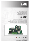
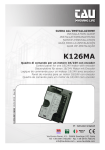
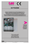
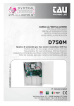
1
>ITALIANO >ENGLISH >DEUTSCH >FRANÇAIS >ESPAÑOL Accessories K125M SCHEDA DI COMANDO PER T-ONE5B (12 Vcc) CONTROL CARD FOR T-ONE5B (12 Vcc) STEUERKARTE FÜR T-ONE5B (12 Vcc) CARTE DE COMMANDE POUR T-ONE5B (12 Vcc) TARJETA DE MANDO PARA T-ONE5B (12 Vcc) Guida all’installazione Installation guide Installationsanleitung Notice d’installation Guía para la instalación TAU srl via E. Fermi, 43 - 36066 Sandrigo (VI) Italia - Tel ++390444750190 - Fax ++390444750376 - E-mail: [email protected] K125M 1 http://www.tauitalia.com rev. 00 del 03/06/2009 Edizione 01 - anno 2009 Italiano Introduzione Il presente manuale è destinato solamente al personale tecnico qualifi cato per l’installazione. Nessuna informazione contenuta nel presente fascicolo può essere considerata d’interesse per l’utilizzatore finale. Questo manuale è allegato alla centralina K125M, non deve pertanto essere utilizzato per prodotti diversi! Avvertenze importanti: Togliere l’alimentazione di rete alla scheda prima di accedervi. La centralina K125M è destinata al comando di un motoriduttore elettromeccanico per l’automazione di cancelli, porte e portoni. Ogni altro uso è improprio e, quindi, vietato dalle normative vigenti. È nostro dovere ricordare che l’automazione che state per eseguire, è classificata come “costruzione di una macchina” e quindi ricade nel campo di applicazione della direttiva europea 98/37/CE (Direttiva Macchine). Questa, nei punti essenziali, prevede che: - l’installazione deve essere eseguita solo da personale qualificato ed esperto; - chi esegue l’installazione dovrà preventivamente eseguire “l’analisi dei rischi” della macchina; - l’installazione dovrà essere fatta a “regola d’arte”, applicando cioè le norme; - infine dovrà essere rilasciata al proprietario della macchina la”dichiarazione di conformità”. Risulta chiaro quindi che l’installazione ed eventuali interventi di manutenzione devono essere effettuati solo da personale professionalmente qualificato, in conformità a quanto previsto dalle leggi, norme o direttive vigenti. Nella progettazione delle proprie apparecchiture, TAU rispetta le normative applicabili al prodotto (vedere la dichiarazione di conformità allegata); è fondamentale che anche l’installatore, nel realizzare gli impianti, prosegua nel rispetto scrupoloso delle norme. Personale non qualificato o non a conoscenza delle normative applicabili alla categoria dei “cancelli e porte automatiche” deve assolutamente astenersi dall’eseguire installazioni ed impianti. Chi non rispetta le normative è responsabile dei danni che l’impianto potrà causare! Si consiglia di leggere attentamente tutte le istruzioni prima di procedere con l’installazione. English Introduction This manual has been especially written for use by qualifi ed fitters. No information given in this manual can be considered as being of interest to end users. This manual is enclosed with control unit K125M and may therefore not be used for different products! D-MNL0K125M Important information: Disconnect the panel from the power supply before opening it. The K125M control unit has been designed to control an electromechanical gear motor for automating gates and doors of all kinds. Any other use is considered improper and is consequently forbidden by current laws. Please note that the automation system you are going to install is classifi ed as “machine construction” and therefore is included in the application of European directive 98/37/EC (Machinery Directive). This directive includes the following prescriptions: - Only trained and qualified personnel should install the equipment; - the installer must first make a “risk analysis” of the machine; - the equipment must be installed in a correct and workmanlike manner in compliance with all the standards concerned; - after installation, the machine owner must be given the “declaration of conformity”. This product may only be installed and serviced by qualified personnel in compliance with current, 2 K125M laws, regulations and directives. When designing its products, TAU observes all applicable standards (please see the attached declaration of conformity) but it is of paramount importance that installers strictly observe the same standards when installing the system. Unqualified personnel or those who are unaware of the standards applicable to the “automatic gates and doors” category may not install systems under any circumstances. Whoever ignores such standards shall be held responsible for any damage caused by the system! Do not install the unit before you have read all the instructions. Deutsch Einleitung Das vorliegende Handbuch ist nur für technisches, zur Installation qualifiziertes Personal bestimmt. Die im vorliegenden Heft enthaltenen Informationen sind für den Endbenutzer nicht interessant. Diese Anleitung liegt der Steuerung K125M bei und darf daher nicht für andere Produkte verwendet werden! Wichtige Hinweise: Die Netzstromversorgung vor dem Zugriff zur Schalt- und Steuertafel abschalten. Die Steuerung K125M dient zum Steuern eines elektromechanischen Getriebemotors für die Automatisierung von Türen und Toren. Jeder andere Einsatz ist unsachgemäß und daher laut gültiger Vorschriften verboten. Unsere Pflicht ist, Sie daran zu erinnern, dass die Automatisierung, die Sie ausführen werden, als „Maschinenkonstruktion“ klassiert ist und daher zum Anwendungsbereich der Europäischen Richtlinie 98/37 (Maschinenrichtlinie) gehört. Nach den wichtigsten Punkten dieser Vorschrift: - darf die Installation ausschließlich von erfahrenem Fachpersonal ausgeführt werden; - muss jener, der die Installation ausführt, vorher eine „Risikoanalyse“ der Maschine machen; - muss die Installation “fachgerecht” bzw. unter Anwendung der Vorschriften ausgeführt sein; - muss dem Besitzer der Maschine die „Konformitätserklärung” ausgehändigt werden. Es ist daher offensichtlich, dass Installation und eventuelle Wartungseingriffe nur von beruflich qualifiziertem Personal in Übereinstimmung mit den Verordnungen der gültigen Gesetze, Normen und Vorschriften ausgeführt werden dürfen. Bei der Planung ihrer Apparaturen hält sich TAU an die für das Produkt anwendbaren Vorschriften (siehe anliegende Konformitätserklärung); von grundlegender Wichtigkeit ist, dass sich auch der Installateur bei der Durchführung der Anlage genauestens an die Vorschriften hält. Personal, das nicht qualifiziert ist oder die Vorschriften nicht kennt, die für die Kategorie “automatische Türen und Tore” anwendbar sind, darf Installationen und Anlagen keinesfalls ausführen. Wer sich nicht an die Vorschriften hält, haftet für die Schäden, die von der Anlage verursacht werden können. Vor der Installation bitte alle Anweisungen genau lesen. Français Introduction Le présent manuel est destiné exclusivement au personnel technique qualifié pour l’installation. Aucune information contenue dans ce fascicule ne peut être considérée comme intéressante pour l’utilisateur final. Ce manuel est joint à l’armoire de commande K125M, il ne doit donc pas être utilisé pour des produits différents ! Recommandations importantes : Couper l’alimentation électrique de l’armoire avant d’y accéder. L’armoire de commande K125M est destinée à la commande d’un motoréducteur électromécanique pour l’automatisation de portails et de portes. K125M 3 Toute autre utilisation est impropre et donc interdite par les normes en vigueur. Nous nous devons de rappeler que l’automatisation que vous vous apprêtez à exécuter est classée comme “construction d’une machine” et rentre donc dans le domaine d’application de la Directive Européenne 98/37/CE (Directive Machines). Cette directive, dans ses grandes lignes, prévoit que : - l’installation doit être exécutée exclusivement par du personnel qualifié et expert ; - qui effectue l’installation devra procéder au préalable à “l’analyse des risques” de la machine; - l’installation devra être faite dans les “règles de l’art”, c’est-à-dire en appliquant les normes; - l’installateur devra remettre au propriétaire de la machine la ”déclaration de conformité”. Il est donc clair que l’installation et les éventuelles interventions de maintenance doivent être effectuées exclusivement par du personnel professionnellement qualifié, conformément aux prescriptions des lois, normes ou directives en vigueur. Dans le projet de ses appareils, TAU respecte les normes applicables au produit (voir la déclaration de conformité jointe) ; il est fondamental que l’installateur lui aussi, lorsque qu’il réalise l’installation, respecte scrupuleusement les normes. Tout personnel non qualifié ou ne connaissant pas les normes applicables à la catégorie des “portails et portes automatiques” doit absolument s’abstenir d’effectuer des installations. Qui ne respecte pas les normes est responsable des dommages que l’installation pourra causer! Nous conseillons de lire attentivement toutes les instructions avant de procéder à l’installation. Español Introducción Este manual está destinado sólo al personal técnico cualificado para la instalación. Ninguna información contenida en este manual puede ser considerada interesante para el usuario final. Este manual acompaña a la central K125M; por lo tanto, ¡no debe utilizarse para otro tipo de producto! Advertencias importantes: Corte la alimentación de red a la tarjeta antes de acceder a ella. La central K125M está destinada al accionamiento de un motorreductor electromecánico para la automatización de cancelas, puertas y portones. Cualquier otro uso es considerado inadecuado y, por consiguiente, está prohibido por las normativas vigentes. Es nuestro deber recordarle que la automatización que está por realizar está clasificada como «construcción de una máquina» y, por consiguiente, entra dentro del campo de aplicación de la directiva europea 98/37/CE (Directiva de máquinas). Dicha normativa, en los puntos fundamentales, prevé que: - la instalación debe ser efectuada sólo por personal cualificado y experto; - la persona que efectúe la instalación deberá analizar preventivamente los riesgos de la máquina; - la instalación deberá ser hecha según las reglas del arte, es decir aplicando las normas; - por último, habrá que expedir al dueño de la máquina la «declaración de conformidad». Por consiguiente, es evidente que la instalación y los posibles trabajos de mantenimiento deben ser efectuados por personal cualificado, de acuerdo con cuanto previsto por las leyes, normas y directivas vigentes. Durante el diseño de sus equipos, TAU respeta las normativas aplicables al producto (véase la declaración de conformidad adjunta); también es fundamental que el instalador, al realizar la instalación, respete escrupulosamente las normas. Personal no cualificado, o que no conozca las normativas aplicables a la categoría de las «cancelas y puertas automáticas», debe abstenerse de efectuar instalaciones. ¡Quien no respeta las normativas es responsable de los daños que la instalación podría provocar! Se aconseja leer con atención todas las instrucciones antes de proceder con la instalación. 4 K125M INSTALLAZIONE Prima di procedere assicurarsi del buon funzionamento della parte meccanica. Verificare inoltre che il gruppo motoriduttore sia stato installato correttamente seguendo le relative istruzioni. Eseguiti questi controlli, assicurarsi che il motoriduttore non abbia un assorbimento durante il movimento superiore a 3 A (per un corretto funzionamento del quadro di comando). L’INSTALLAZIONE DELL’APPARECCHIATURA DEVE ESSERE EFFETTUATA “A REGOLA D’ARTE” DA PERSONALE QUALIFICATO COME DISPOSTO DAL D.M. 37/08. NB : si ricorda l’obbligo di mettere a massa l’impianto nonché di rispettare le normative sulla sicurezza in vigore in ciascun paese. LA NON OSSERVANZA DELLE SOPRAELENCATE ISTRUZIONI PUÒ PREGIUDICARE IL BUON FUNZIONAMENTO DELL’APPARECCHIATURA E CREARE PERICOLO PER LE PERSONE, PERTANTO LA “CASA COSTRUTTRICE” DECLINA OGNI RESPONSABILITÀ PER EVENTUALI MAL FUNZIONAMENTI E DANNI DOVUTI ALLA LORO INOSSERVANZA. INSTALLATION Before proceeding, make sure the mechanical components work correctly. Also check that the gear motor assembly has been installed according to the instructions. Then make sure that the power consumption of the gear motor is not greater than 3A (otherwise the control panel may not work properly). THE EQUIPMENT MUST BE INSTALLED “EXPERTLY” BY QUALIFIED PERSONNEL AS REQUIRED BY LAW. NB : it is compulsory to earth the system and to observe the safety regulations that are in force in each country. IF THESE ABOVE INSTRUCTIONS ARE NOT FOLLOWED IT COULD PREJUDICE THE PROPER WORKING ORDER OF THE EQUIPMENT AND CREATE HAZARDOUS SITUATIONS FOR PEOPLE. FOR THIS REASON THE “MANUFACTURER” DECLINES ALL RESPONSIBILITY FOR ANY MALFUNCTIONING AND DAMAGES THUS RESULTING. INSTALLATION Bevor man weitermacht, den korrekten Betrieb des mechanischen Teils überprüfen und konrollieren, ob der Getriebemotor richtig nach den jeweiligen Anweisungen installiert ist. Nachdem diese Kontrollen ausgefürt sind, muss sichergestellt werden, dass der Getriebemotor nicht mehr als 3A Stromaufnahme hat (für den korrekten Betrieb der Steuertafel). DAS GERÄT MUSS GEMÄß DEM GESETZ VON QUALIFIZIERTEM PERSONAL INSTALLIERT WERDEN. N.B.: Bitte beachten Sie, dass die Erdung der Anlage und die Einhaltung der in jedem Land gültigen Sicherheitsvorschriften Pflicht ist. DAS NICHTEINHALTEN DER OBEN ANGEFÜHRTEN ANLEITUNGEN KANN DEN EINWANDFREIEN BETRIEB DES GERÄTS BEEINTRÄCHTIGEN UND GEFAHREN FÜR PERSONEN HERVORRUFEN. DER HERSTELLER HAFTET DAHER NICHT FÜR BETRIEBSSTÖRUNGEN UND SCHÄDEN, DIE AUF DAS NICHTEINHALTEN DER ANLEITUNGEN ZURÜCKZUFÜHREN SIND. INSTALLATION Avant de procéder, s’assurer du bon fonctionnement de la partie mécanique. Vérifier en outre que le groupe opérateur a été correctement installé en suivant les instructions correspondantes. Une fois que ces contrôles ont été effectués, s’assurer que l’absorption de l’opérateur ne dépasse pas 3A (pour un fonctionnement correct de l’armoire de commande). L’INSTALLATION DE L’EQUIPEMENT DOIT ETRE REALISEE “SELON LES REGLES DE L’ART” PAR LE PERSONNEL COMPETENT AYANT LES QUALITES REQUISES PAR LA LOI. N.B.: nous rappelons l’obligation de mettre l’installation à la terre et de respecter les normes de sécurité en vigueur dans le pays d’installation. LANON OBSERVATION DES INSTRUCTIONS POURRAIT COMPROMETTRE LE BON FONCTIONNEMENT DE L’APPAREILLAGE ET CREER UN DANGER POUR LES PERSONNES, PAR CONSEQUENT LA MAISON DECLINE TOUTE RESPONSABILITE POUR D’EVENTUELLES DETERIORATIONS DUES A UNE UTILISATION NON APPROPRIEE OU NON CONFORME AU MODE D’EMPLOI. INSTALACIÓN Antes de continuar, asegúrese de que la parte mecánica funcione bien. También controle que el grupo motorreductor esté instalado correctamente siguiendo las instrucciones respectivas. Una vez concluidos los controles, verifique que l’absorción del motorreductor no supere 3A (para un funcionamiento correcto del quadro de mandos). La instalación del equipo debe ser hecha correctamente por personal que reÚna los requisitos dispuestos por la ley. N.B.: se recuerda que es obligatorio conectar a tierra el equipo y respetar las normas de seguridad vigentes en cada país. la inobservancia de las instrucciones antedichas puede perjudicar el funcionamiento correcto del equipo y constituir un peligro para las personas; el “fabricante” no se considera responsable por posibles problemas de funcionamiento y daños que de ellos se deriven. K125M 5 INDICE CONTENTS INHALTSVERZEICHNIS INDEX ÍNDICE Pag. 7 ITALIANO Pag. 14 ENGLISH Pag. 21 DEUTSCH Pag. 28 FRANÇAIS Pag. 35 ESPAÑOL Pag. 42 SCHEMA CABLAGGIO K123M / K123M WIRING DIAGRAM / SCHALTPLAN DER K123M / SCHÉMA CÂBLAGE K123M / ESQUEMA DEL CABLEADO K123M Pag. 44 DICHIARAZIONE CE / KONFORMITÄTSERKLÄRUNG / DECLARATION OF CONFORMITY / DECLARATlON DE CONFORMITY / DECLARACIÓN DE CONFORMIDAD Pag. 46 GARANZIA / GARANTIE / GUARANTEE / GARANTIE / GARANTÍA 6 K125M Italiano SCHEDA COMANDO PER MOTORIDUTTORE T-ONE5B LOGICA CON MICROPROCESSORE STATO DEGLI INGRESSI VISUALIZZATO DA LEDs PROTEZIONE INGRESSO LINEA CON FUSIBILE FUNZIONE “INGRESSO PEDONALE” CIRCUITO DI LAMPEGGIO INCORPORATO RADIO RICEVITORE 433,92 MHz INTEGRATO A 2 CANALI (CH) SCHEDA CARICA BATTERIA (INTEGRATA) CONNETTORE PER BATTERIA SENSORE AD ENCODER PER RILEVAMENTO OSTACOLI ED AUTOAPPRENDIMENTO DELLA CORSA RALLENTAMENTO REGOLABILE DIAGNOSTICA DEL DIFETTO FUNZIONE VISUALIZZATO DA LED EN CONFORME E CERTIFICABILE FINO A 500 KG DI ANTA ATTENZIONE: - non utilizzare cavi unifilari (a conduttore unico), es. quelli citofonici, al fine di evitare interruzioni sulla linea e falsi contatti; - non riutilizzare vecchi cavi preesistenti. COLLAUDO A collegamento ultimato: I Leds verdi LS devono essere tutti accesi (corrispondono ciascuno ad un ingresso Normalmente Chiuso). Si spengono solo quando sono interessati i comandi ai quali sono associati. I Leds rossi LS devono essere tutti spenti (corrispondono ciascuno ad un ingresso Normalmente Aperto) si accendono solo quando sono interessati i comandi ai quali sono associati. Fa eccezione il led di diagnostica DL3 che deve essere sempre acceso. CARATTERISTICHE TECNICHE Alimentazione scheda Potenza max. motore c.c. Fusibile rapido protezione alimentazione ingresso 13,5 Vac (F1 - 5x20) Fusibile rapido protezione motore (F2 - 5x20) Fusibile rapido protezione ausiliari 18 V dc (F3 - 5x20) Fusibile rapido protezione batteria (F4 - 5x20) Tensione circuiti alimentazione motore Tensione alimentazione circuiti dispositivi ausiliari Tensioni alimentazioni circuiti logici Temperatura di funzionamento Grado di protezione del contenitore K125M 13,5 Vac - 50 Hz 50 W - 18 Vdc F 16 A F 10 A F2A F 10 A 18 Vdc 18 Vdc 5 Vdc -20 °C ÷ +70 °C IP 44 7 LED DI DIAGNOSI DL1 (PEDESTRIAN) DL2 (OPEN/CLOSE) DL3 (ERR) DL4 (STOP) DL5 (PHOTO) DL6 (SENSITIVE EDGE) DL7 (TENSION) led rosso di segnalazione pulsante PEDONALE led rosso di segnalazione pulsante APRE/CHIUDE led rosso di segnalazione ERRORI led verde di segnalazione pulsante STOP led verde di segnalazione FOTOCELLULA led verde di segnalazione BORDO SENSIBILE led verde di segnalazione PRESENZA RETE (anche tensione batteria) COLLEGAMENTI ALLA MORSETTIERA FS1 - FS2 ingresso alimentazione scheda 13,5 Vac - Alimentato dal trasformatore toroidale riposto nell’apposito vano del motore T-ONE5B e protetto da fusibile sull’alimentazione 230 Vac. 1 - 3 (Fixed safety edge) ingresso BORDO SENSIBILE (Bordo sensibile resistivo o costa fissa); Funziona solo durante la fase di apertura e provoca la fermata temporanea del cancello e una parziale richiusura dello stesso per circa 20 cm. liberando così l’eventuale ostacolo. 1= BORDO SENSIBILE, 3= COMUNE. N.B. Se si collega un bordo sensibile resistivo porre il dip-switch nr 9 in ON; Se si collega una costa fissa con contatto NC porre il dip-switch nr 9 in OFF. 2-3 (Photocell) ingresso FOTOCELLULE O DISPOSITIVI DI SICUREZZA attivi in chiusura (contatto Normalmente Chiuso); il loro intervento, in fase di chiusura provoca l’arresto seguito dalla totale riapertura del cancello, in fase di apertura provoca la fermata temporanea del cancello fino a rimozione dell’ostacolo rilevato (solo se programmato dip switch nr. 3 in ON). Nel caso di più dispositivi di sicurezza, collegare tutti i contatti NC IN SERIE. 2= FOTOCELLULA. N.B. Il trasmettittore della fotocellula deve sempre essere alimentato dai morsetti nr 10 11, in quanto su di esso si effettua la verifica del sistema di sicurezza (Fototest). Per eliminare la verifica del sistema di sicurezza, o quando non si usano le fotocellule, porre il dip-switch nr 6 in OFF. Se il fototest non va a buon fine, la centralina non funziona. 4-5 (Stop) ingresso pulsante STOP (contatto Normalmente Chiuso); Arresta il cancello dovunque si trovi, inibendo temporaneamente la chiusura automatica, se programmata. 4= COMUNE, 5= STOP. 4-6 (Open/Close) ingresso pulsante APRE/CHIUDE (contatto Normalmente Aperto); Comanda l’apertura e la chiusura del cancello ed è regolato nel funzionamento dai dipswitches 2 e 4. 5= APRE/CHIUDE. 4-7 (Pedestrian) ingresso pulsante PEDONALE (contatto Normalmente Aperto); Comanda l’apertura e la chiusura parziale del cancello per ~1 m di corsa ed è regolato nel funzionamento dai dip-switches 2 e 4. 7= PEDONALE. 8-9 (Photocell RX ) uscita 18 Vdc, max. 15 W, per l’ALIMENTAZIONE DELLE RX ED EVENTUALI ALTRI TX DELLE FOTOCELLULE, RICEVITORI ESTERNI, etc; collegare max. n° 3 coppie di fotocellule. 8= NEGATIVO, 9= POSITIVO. 8 K125M 10 - 11 (Photocell TX) uscita 18 Vdc, per l’ALIMENTAZIONE DEL TX DELLE FOTOCELLULE (solo quello che effettua il Fototest) max. nr. 1 trasmettitore fotocellule. 10= NEGATIVO, 11= POSITIVO. 12 - 13 (Flashing light) uscita LAMPEGGIANTE 18 Vdc, max. 20 W. Il segnale fornito è già opportunamente modulato per l’uso diretto. La frequenza di lampeggio è doppia in fase di chiusura. 12= NEGATIVO, 13= POSITIVO. 14 - 15 (Gate open warning light) uscita per SPIA CANCELLO APERTO 18 Vdc, max. 3 W; durante l’apertura del cancello la spia lampeggia lentamente, a cancello aperto resta accesa e durante la chiusura lampeggia a velocità doppia. 14= NEGATIVO, 15= POSITIVO. 16 - 17 (2nd radio channel) uscita 2° CANALE RADIO (il suo funzionamente dipende dai dipswitch nr 7 - 8) da utilizzarsi per aprire/chiudere un altro cancello o per comandare le luci del giardino, o per la funzione “ILLUMINAZIONE DI ZONA”. 18 - 19 (Antenna) Ingresso ANTENNA per RX 433,92 MHz incorporata. 18= MASSA, 19= SEGNALE. 20 - 21 uscita alimentazione MOTORE 18 Vdc max. 50 W. 20= NEGATIVO, 21= POSITIVO. M5 innesto rapido per connessione ENCODER. Blu= 0 Vcc (GND), marrone= 5 Vcc (+5V), bianco= SEGNALE ENCODER (ENC). 22 - 23 ingresso BATTERIA 12V - 7,2Ah. PROCEDURA DI MEMORIZZAZIONE ATTENZIONE: Dopo aver alimentato il quadro di comando attendere 2 sec. prima di iniziare a svolgere le manovre di regolazione. N.B. Il cancello deve necessariamente avere i fermi meccanici di sicurezza sia in apertura che in chiusura. Terminata l’installazione dell’automazione: 1_ portare il cancello a 1 m ca. dalla battuta in chiusura; 2_ posizionare il dip-switch nr. 10 in ON; 3_ comandare l’automazione agendo su uno dei seguenti ingressi: A/C, radiocomando o pulsante scheda (PROG). 4_ il cancello deve cominciare a chiudere. N.B.: nel caso dovesse aprirsi, sospendere la programmazione resettando il quadro elettrico (togliere l’alimentazione al quadro per almeno 5 sec. e rimettere il dip-switch nr. 10 in OFF), e quindi a quadro disalimentato invertire tra di loro i fili di alimentazione del motore. Riprendere poi la procedura dal punto 1. 5_ effettuata la chiusura, trascorso un tempo di circa 2 sec., viene eseguita automaticamente un’apertura totale; 6_ ad apertura completata, attendere che il led DL3 sia acceso fisso, quindi posizionare il dip-switch nr. 10 in OFF; 7_ l’automazione è ora pronta per il funzionamento. Effettuare le regolazioni logiche. N.B.: agendo su qualsiasi regolazione del quadro di comando (trimmer o dip-switches) è necessario effettuare una manovra completa (apertura e chiusura) dell’automazione per rendere attive le nuove impostazioni. K125M 9 REGOLAZIONI LOGICHE TRIMMER RALL. Regolazione rallentamento: da 0 a 150 cm circa prima del finecorsa; Nota: prima di impostare il rallentamento, l’automazione deve eseguire una manovra completa di apertura e chiusura. FR. Regolazione sensibilità rilevamento ostacoli. Regolare il trimmer per una spinta del cancello atta a garantire il funzionamento, facendo attenzione a non superare quella consentita dalle norme in uso (EN 12453). Ruotando il trimmer in senso orario (+) si aumenta la coppia motore, viceversa, ruotandolo in senso antiorario (-), diminuisce. T.C.A. Regolazione Tempo di Chiusura Automatica: da 3 a 255 secondi ca. (vedi dip-switch nr. 1); Dip switch 1 on: ad apertura completata, la chiusura del cancello è automatica trascorso un tempo impostato sul trimmer T.C.A.; off: la chiusura necessita di un comando manuale; 2 on: ad automazione funzionante, una sequenza di comandi di apertura/chiusura induce il cancello ad una APERTURA-CHIUSURA-APERTURA-CHIUSURA, etc. (vedi anche dip switch 4); off: nelle stesse condizioni, la stessa sequenza di comandi di apertura/chiusura induce il cancello ad una APERTURA-STOP-CHIUSURA-STOP-APERTURA-STOP, etc. (funzione passo-passo); 3 on: durante la fase di apertura la fotocellula interviene arrestando il cancello fino a rimozione dell’ostacolo rilevato. Alla rimozione dell’ostacolo il cancello riprende l’apertura; off: durante la fase di apertura la fotocellula non interviene; 4 on: funzione NO-REVERSE attiva; il cancello ignora i comandi di chiusura durante l’apertura e l’inversione di marcia avviene solo in fase di chiusura; off: azionando il pulsante apre-chiude avremo una inversione di marcia anche in fase di apertura; 5 on: la funzione prelampeggio è abilitata; off: la funzione prelampeggio è disabilitata; 6 on: la funzione “verifica delle fotocellule” è inserita; off: la funzione “verifica delle fotocellule” è disinserita. N.B.: da utilizzare quando non si usano le fotocellule; 7 - 8 funzionamento 2° CANALE RADIO (morsetti nr 16 - 17) Dip 7 Dip 8 Funzione Contatto cancello aperto: il contatto si attiva all’apertura del cancello, rimane OFF OFF attivo durante il tempo di apertura, durante il TCA e durante la richiusura. Si disattiva una volta che il cancello ha completato la chiusura. Funzione bistabile attiva: all’impulso del radiocomado il contatto si attiva e OFF ON rimane tale fino al successivo impulso. Funzione monostabile attiva 2 sec.: all’impulso del radiocomado il contatto si ON OFF attiva e rimane tale per 2 sec. Funzione monostabile attiva 180 sec.: all’impulso del radiocomado il contatto ON ON si attiva e rimane tale per 180 sec. 9 on: BORDO SENSIBILE RESISTIVO (morsetto nr 1); off: COSTA FISSA (contatto NC - morsetto nr 1); 10 on: si abilita la funzione di memorizzazione per l’autoapprendimento della corsa; off: posizione in cui lasciare il dip-switch al termine della procedura di memorizzazione. 10 K125M CARATTERISTICHE DELLA K125M LED - DL3 Il led, oltre ad indicare la presenza dell’alimentazione, segnala eventuali errori con una serie di lampeggi predefiniti: • sempre acceso: funzionamento regolare; • 1 lampeggio: tensione della batteria tampone inferiore a 11,3 Vdc; Controllare l’alimentazione di rete, caricare la batteria, sostituire la batteria; • 2 lampeggi: errore fototest; Disabilitare fototest (dip-switch 6 in OFF), verificare funzionamento fotocellule e loro collegamento; • 3 lampeggi: mancanza tensione di rete; Controllare interruttore magnetotermico (a monte dell’impianto), controllare fusibili; • 4 lampeggi: superamento limite max. di corrente; Picco di eccessivo assorbimento del motoriduttore, controllare l’assenza di ostacoli lungo la corsa del cancello, verificare l’assorbimento di corrente del motore a vuoto e applicato al cancello; • 5 lampeggi: assenza segnale encoder; Controllare cablaggio, verificare encoder tramite TEST-ENCODER (opzionale), verificare che il motore giri liberamente alimentato direttamente dalla batteria, verificare fusibile F2; • 6 lampeggi: presenza ostacolo dopo 5 tentativi di chiusura falliti; Controllare l’assenza di ostacoli lungo la corsa del cancello e la scorrevolezza dello stesso; • 7 lampeggi: non è stata eseguita alcuna procedura di memorizzazione; Eseguire procedura di memorizzazione. L’indicazione di più errori viene eseguita con una pausa di 2 sec. tra una segnalazione e l’altra. L’indicazione degli errori persiste fino all’esecuzione di una manovra completa (apertura e chiusura) dell’automazione. Nel caso di 5 interventi consecutivi (durante la stessa manovra di apertura o chiusura) da parte dei sistemi di sicurezza, la centrale entrerà in fase di corsa rallentata alla ricerca della battuta in chiusura. É necessario che l’automazione completi una manovra (apertura e successiva chiusura) per resettarsi, altrimenti ripartirà la fase di ricerca della battuta di fine corsa dopo ogni singolo intervento dei dispositivi di sicurezza. SCHEDA CARICA BATTERIA (INTEGRATA) Se si collega la batteria, in assenza di rete l’automazione risulta comunque funzionante. Nel caso la tensione scenda sotto gli 11,3 Vdc, l’automazione cessa di funzionare (il quadro di comando rimane alimentato); quando, invece, scende sotto i 10,2 Vdc, la scheda sgancia completamente la batteria (il quadro di comando non è più alimentato). RILEVAMENTO OSTACOLI La funzione di rilevamento ostacoli (impostabile tramite trimmer FR) intervenendo in fase di apertura dell’automazione provoca una richiusura della stessa di 20 cm ca., mentre in fase di chiusura provoca un’apertura totale. ATTENZIONE: la logica del quadro di comando può interpretare un attrito meccanico come un eventuale ostacolo. RALLENTAMENTO Per evitare che il cancello sbatta alla fine della corsa, è possibile impostare (tramite il trimmer RALL) il rallentamento in apertura e in chiusura su una distanza variabile da 10 a 150 cm. (ruotando il trimmer in senso orario si aumenta la distanza di rallentamento; viceversa, ruotandolo in senso antiorario la distanza di rallentamento si accorcia). Si consiglia di impostare la distanza di rallentamento tenendo conto del peso del cancello e degli attriti meccanici in gioco. N.B.: il pulsante PROG della scheda ha la stessa funzione del tasto APRE/CHIUDE. K125M 11 FUNZIONI AVANZATE Funzione orologio: è possibile utilizzare un timer (esempio settimanale) collegato all’ingresso del pulsante apre-chiude per mantenere aperto il cancello in determinate fascie orarie e permetterne poi la richiusura automatica. N.B. Il cancello rimane aperto finchè l’ingresso Ap/Ch rimane impegnato. Funzione “solo Apre”: ponendo il dip 1 ed il dip 4 in ON, l’ingresso Ap/Ch funzionerà solo come comando di apertura, mentre il cancello chiuderà esclusivamente una volta trascorso il tempo di chiusura automatica. Funzione “contatto cancello aperto”: ponendo il dip 7 ed il dip 8 in OFF, il 2° ch radio (morsetti nr 16 - 17) funzionerà da contatto pulito che indica quando il cancello è aperto. È possibile utilizzare questa funzione per collegare una “ILLUMINAZIONE DI ZONA” o come segnalazione di cancello aperto. RADIO RICEVITORE 433,92 MHz INTEGRATO Il radio ricevitore può apprendere fino ad un max di 30 codici a dip-switches (TXD2, TXD4, BUG2, BUG4, SLIM, SLIM-C) o rolling code (BUG2R, BUG4R, SLIM-R) da impostare liberamente su due canali. Il primo canale comanda direttamente la scheda di comando per l’apertura dell’automazione; il secondo canale comanda un relè per un contatto pulito N.A. in uscita ai morsetti nr 16 e 17 (max 24 Vac, 1 A). La modalità di apprendimento (dip-switches o rolling code) viene determinata dal primo radiocomando e rimarrà la stessa fino alla cancellazione totale di tutti i codici di entrambi i canali. APPRENDIMENTO RADIOCOMANDI CH1 = APRE/CHIUDE CH2 = 2° canale 1_ premere brevemente il tasto CH1 se si desidera associare un radiocomando alla funzione APRE/ CHIUDE; 2_ il led DL3 si spegne per indicare la modalità di apprendimento dei codici (se non viene immesso nessun codice entro 10 secondi, la scheda esce dalla modalità di programmazione); 3_ premere il tasto del radiocomando che si desidera utilizzare; 4_ il led DL3 si riaccende per segnalare l’avvenuta memorizzazione (se ciò non accade, attendere 10 secondi e riprendere dal punto 1); 5_ se si desidera memorizzare altri radiocomandi, ripetere la procedura dal punto 1 fino ad un massimo di 30 trasmettitori; 6_ se si desidera effettuare la memorizzazione sul 2° canale, ripetere la procedura dal punto 1 utilizzando il tasto CH2 anzichè il tasto CH1; 7_ se si desidera uscire dalla modalità di apprendimento senza memorizzare un codice, premere brvemente il tasto CH1 o il tasto CH2. N.B.: nel caso di raggiungimento del nr massimo di radiocomandi (nr 30), il led DL3 inizierà a lampeggiare velocemente per circa 3 secondi senza però eseguire la memorizzazione. PROGRAMMAZIONE REMOTA TRAMITE SLIM-R e BUG-R È possibile anche eseguire l’apprendimento remoto della nuova versione di radiocomandi SLIM-R e BUG-R, ossia senza agire direttamente sui tasti di programmazione della ricevente. Sarà sufficiente disporre di un radiocomando già programmato nella ricevente per poter aprire la procedura di programmazione remota dei nuovi radiocomandi, programmati tramite TAUPROG. 12 K125M Attivazione della modalità di autoapprendimento nella centrale e memorizzazione del nuovo radiocomando. 1. Nel radiocomando SLIM-R o BUG-R già memorizzato e funzionante ”vecchio”, premere e tenere premuto il tasto del canale 1 2. Premere per 3 volte il tasto del canale 2. 3. Rilasciare i tasti. Il led del radiocomando inizierà a lampeggiare indicando l’abilitazione della modalità di autoapprendimento. 4. Premere il tasto corrispondente al canale che si dovrà memorizzare. 5. A questo punto la centrale confermerà il passaggio in modalità di programmazione accendendo il lampeggiante. 6. Premere sul nuovo radiocomando il tasto da memorizzare. Se la programmazione è andata a buon fine il lampeggiante della centrale si spegne e anche il nuovo radiocomando è pronto all’uso. CANCELLAZIONE RADIOCOMANDI 1_ tenere premuto per 3 secondi ca. il tasto CH1 al fine di cancellare tutti i radiocomandi ad esso associati; 2_ il led DL3 inizia a lampeggiare lentamente per indicare che la modalità di cancellazione è attivata; 3_ tenere premuto nuovamente il tasto CH1 per 3 secondi; 4_ il led DL3 si spegne per 3 secondi ca. per poi riaccendersi fisso ad indicare l’avvenuta cancellazione; 5_ riprendere la procedura dal punto 1 utilizzando il tasto CH2 per cancellare tutti i radiocomandi ad esso associati; 6_ se si desidera uscire dalla modalità di cancellazione senza memorizzare un codice, premere brevemente il tasto CH1 o il tasto CH2. ATTENZIONE: Se si desidera memorizzare un nuovo tipo di telecomando (es: da dip-switches a rolling code o viceversa) è necessario cancellare entrambi i canali. MALFUNZIONAMENTI: POSSIBILI CAUSE E RIMEDI 1_ L’automazione non parte a_ Verificare con lo strumento (Multimetro) la presenza dell’alimentazione 230Vac; b_ Verificare che i contatti N.C. della scheda siano effettivamente normalmente chiusi (3 led verdi accesi) e che i led rossi dei comandi di apertura siano spenti; c_ Impostare il dip 6 (fototest) su OFF; d_ Aumentare il trimmer FR al massimo; e_ Controllare con lo strumento (Multimetro) che i fusibili siano integri. 2_ Il radiocomando ha poca portata a_ Controllare che il collegamento della massa e del segnale dell’antenna non sia invertito; b_ Non eseguire giunzioni per allungare il cavo dell’antenna; c_ Non installare l’antenna in posizioni basse o in posizioni nascoste dalla muratura o dal pilastro; d_ Controllare lo stato delle pile del radiocomando. 3_ Il cancello si apre al contrario a_ Invertire il collegamento del motore (morsetti nr 20 - 21). K125M 13 English CONTROL BOARD FOR T-ONE5B GEARMOTOR MICROPROCESSOR-CONTROLLED LOGIC INPUT STATUS LED’S LINE INPUT FUSE “PEDESTRIAN GATE” FUNCTION BUILT-IN FLASHING LIGHT CIRCUIT 433.92 MHz 2 CHANNEL BUILT-IN RADIO RECEIVER (CH) BATTERY CHARGER BOARD (INTEGRATED) BATTERY CONNECTOR ENCODER SENSOR FOR OBSTACLE DETECTION AND SELF-LEARNING OF TRAVEL ADJUSTABLE DECELERATION DIAGNOSTICS OF MALFUNCTIONS SIGNALLED BY LED EN COMPLIANT AND CERTIFIABLE UP TO 500 KG LEAF ATTENTION: - do not use single cables (with one single wire), ex. telephone cables, in order to avoid breakdowns of the line and false contacts; - do not re-use old pre-existing cables. TESTING When you have completed the connection: All the green LEDs must be on (each of them corresponds to a Normally Closed input). The go off only when the controls to which they are associated are operated. All the red LS LEDs must be off (each of them corresponds to a Normally Open input). The light up only when the controls to which they are associated are operated. Except for the DL3 diagnostics led which must always be on. TECHNICAL CHARACTERISTICS Board power supply Max motor power DC Fast acting fuse for protection of input power supply 13.5 Vac (F1 - 5x20) Fast acting fuse for motor protection (F2 - 5x20) Fast acting fuse for protection of auxiliary circuits 18 V dc (F3 - 5x20) Fast acting fuse for protection of battery (F4 - 5x20) Motor power supply circuits voltage Auxiliary device circuits supply voltage Logic circuits supply voltages Operating temperature Box protected to 14 K125M 13,5 Vac - 50 Hz 50 W - 18 Vdc F 16 A F 10 A F2A F 10 A 18 Vdc 18 Vdc 5 Vdc -20 °C ÷ +70 °C IP 44 DIAGNOSTICS LED DL1 (PEDESTRIAN) DL2 (OPEN/CLOSE) DL3 (ERR) DL4 (STOP) DL5 (PHOTO) DL6 (SENSITIVE EDGE) DL7 (TENSION) PEDESTRIAN button red LED signal OPEN/CLOSE button red LED signal ERRORS red LED signal STOP button green LED signal PHOTOCELL green LED signal SENSITIVE EDGE green LED signal POWER ON (also battery voltage) green LED signal CONNECTIONS TO TERMINAL BOARD FS1 - FS2 board supply input 13,5 Vac – Powered by the toroidal transformer housed in the T-ONE5B motor and protected by a fuse on the 230 Vac power supply. 1 - 3 (Fixed safety edge) SENSITIVE EDGE input (resistive sensitive edge or fixed safety edge); Works only when the gate is opening; temporarily stops the gate and partially closes it by about 20 cm in order to allow the obstacle to be removed. 1= SENSITIVE EDGE, 3= COMMON. N.B. If a resistive sensitive edge is connected, set dip-switch no. 9 to ON; If a fixed safety edge with NC contact is connected, set dip-switch no. 9 to OFF. 2-3 (Photocell) input for PHOTOCELLS OR SAFETY DEVICES active during closure (Normally Closed contact); They stop the gate during closing and totally reopen it; they temporarily stop the gate during opening in order to allow the obstacle to be removed (if dip switch n° 3 set to ON). If there is more than one safety device, connect all the NC contacts IN SERIES. 2= PHOTOCELL. N.B. The photocell transmitter must always be supplied by terminals no. 10 - 11, since the safety system test (phototest) is carried out on it. To override the testing of the safety system, or when the photocells are not used, set dip-switch no. 6 to OFF. If the phototest is not successful, the control unit will not operate. 4-5 (Stop) STOP pushbutton input (Normally Closed contact); It stops the gate in any position, temporarily inhibiting its automatic closing, if programmed. 4= COMMON, 5= STOP. 4-6 (Open/Close) OPEN/CLOSE pushbutton input (Normally Open contact); It commands the opening and closing of the gate and its operation is controlled by dip-switches 2 and 4. 5= OPEN/CLOSE. 4-7 (Pedestrian) PEDESTRIAN pushbutton input (Normally Open contact); It commands the partial opening and closing of the gate for ~1 m of travel and its operation is controlled by dip-switches 2 and 4. 7= PEDESTRIAN. 8-9 (Photocell RX ) 18 Vdc, max. 15 W, output to POWER THE RXs AND ANY OTHER TXs OF PHOTOCELLS THAT ARE PRESENT, EXTERNAL RECEIVERS, etc.; connect a max. of 3 pair of photocells. 8= NEGATIVE, 9= POSITIVE. 10 - 11 (Photocell TX) 18 Vdc, output for PHOTOCELL TX (only the one that performs the Phototest) max. no. 1 photocell transmitter. 10= NEGATIVE, 11= POSITIVE. K125M 15 12 - 13 (Flashing light) FLASHING LIGHT output 18 Vdc, max. 20 W. The signal is already modulated for direct use. Flashing frequency during closing is double. 12= NEGATIVE, 13= POSITIVE. 14 - 15 (Gate open warning light) GATE OPEN LED output 18 Vdc, max. 3 W; during opening of the gate the warning light flashes slowly, when the gate is open it remains steadily illuminated and during closure it flashes twice as fast. 14= NEGATIVE, 15= POSITIVE. 16 - 17 (2nd radio channel) 2nd RADIO CHANNEL output (its operation depends on dip-switches nos. 7 - 8) to be used for opening/closing another gate, for controlling garden lights or for the “ZONE LIGHTING” function. 18 - 19 (Antenna) 433,92 MHz built-in RX ANTENNA input. 18= EARTH, 19= SIGNAL. 20 - 21 MOTOR supply output 18 Vdc, max. 50 W. 20= NEGATIVE, 21= POSITIVE. M5 quick coupling for ENCODER connection. Blue= 0 Vdc (GND), brown= 5 Vdc (+5V), white= ENCODER SIGNAL (ENC). 22 - 23 BATTERY 12V - 7,2Ah input. MEMORIZATION PROCEDURE WARNING: After powering the control panel, wait 2 seconds before you start performing the adjustment operations. N.B. The gate must be equipped with the opening and closing safety stops. When you have completed the installation procedures : 1_ bring the gate to approx. 1 m from the closing travel limit; 2_ set dip-switch no. 10 to ON; 3_ operate the automation using one of the following inputs: A/C, radio control or card button (PROG); 4_ the gate must start to close. N.B.: if it opens, stop the programming procedure by resetting the electric panel (disconnect the power supply to the panel for at least 5 sec. and set dip-switch no. 10 to OFF); with the control panel disconnected, exchange the motor supply wires. Restart the procedure from point 1. 5_ when the gate has closed, after approximately 2 seconds a complete opening manoeuvre is executed automatically; 6_ when the gate has opened, wait for the DL3 led to be fixedly on, then set dip-switch no.10 to OFF; 7_ the automation is now ready for operation. Make the logic adjustments. N.B.: When any adjusting devices (trimmers or dip-switches) on the control panel are operated, a complete manoeuvre must be carried out in order for the new settings to take effect. 16 K125M LOGIC ADJUSTMENTS TRIMMER RALL. Deceleration adjustment: from 0 to 150 cm before the limit switch; Note: the automation must perform a complete opening and closing manoeuvre before setting the deceleration. FR. Obstacle detection sensitivity adjustment. The trimmer is set to provide sufficient thrust to work the gate without exceeding the limits established by current standards (EN 12453). Turning the trimmer clockwise (+) increases the motor torque, turning it anticlockwise (-) reduces it. T.C.A. Automatic Closing time adjustment: from about 3 to 255 seconds (see dip-switch no. 1); Dip switch 1 on: after opening, the gate automatically closes when the delay set on the T.C.A. trimmer expires. off: automatic closing disabled. 2 on: with automatic closing enabled, a sequence of open/close commands causes the gate to OPENCLOSE-OPEN-CLOSE etc (see also dip switch 4). off: in the same conditions, the same command sequence causes the gate to OPEN-STOPCLOSESTOP-OPEN-STOP (step-by-step). 3 on: during opening, the photocell cuts in to stop the gate until the obstacle is removed. When the obstacle is removed the gate resumes opening; off: during opening, the photocell does not cut in. 4 on: NO-REVERSE function activated; the gate ignores the closure commands during opening and reversal of movement occurs only during closure; off: the open-close pushbutton reverses the direction of movement of the gate even while it is opening. 5 on: the pre-flashing function enabled. off: the pre-flashing function disabled. 6 on: the “photocell test” function is enabled; off: the “photocell test” function is disabled. N.B.: to be used when the photocells are not used. 7 - 8 2nd RADIO CHANNEL operation (terminals no. 16 - 17) Dip 7 Dip 8 Function Gate contact open: The contact activates on opening the gate and remains OFF OFF active during the open time, during the TCA and during reclosure. It deactivates once the gate has completed its closure movement. Bistable function active: the radio control impulse causes the contact to OFF ON activate and remain active until the subsequent impulse. Monostable function active for 2 sec.: the radio control impulse causes the ON OFF contact to activate and remain active for 2 sec. Monostable function active for 180 sec.: the radio control impulse causes the ON ON contact to activate and remain active for 180 sec. 9 on: RESISTIVE SENSITIVE EDGE (terminal no. 1); off: FIXED EDGE (NC contact – terminal no. 1); 10 on: the memorization function is enabled for self-learning of the travel; off: leave the dip-switch in this position when the memorization procedure has been completed. K125M 17 K125M CHARACTERISTICS LED - DL3 The LED, besides indicating that the power supply is connected, also signals errors with a series of pre-defined flashes: • steady light: normal operation; • 1 flash: buffer battery voltage lower than 11.3 Vdc; Check the mains power supply, charge the battery, replace the battery; • 2 flashes: phototest error; Disable phototest (dip-switch 6 OFF), check operation and connection of photocells; • 3 flashes: power failure; Check the thermal-magnetic circuit breaker (upstream from system), check the fuses; • 4 flashes: max current limit exceeded; Gearmotor has exceeded absorption limits, check for obstacles across the path of the gate, check the current absorption of the motor when loadless and under load; • 5 flashes: absence of encoder signal; Check wiring, check encoder through TEST-ENCODER (optional), verify that the motor turns freely if powered directly by the battery, check fuse F2; • 6 flashes: presence of obstacle after 5 failed attempts to close; Make sure there are no obstacles across the path of the gate and that it slides smoothly; • 7 flashes: no memorization procedure has been executed; Execute memorization procedure. Multiple errors are signalled by a 2-second pause between signals. Errors will continue to be signalled until a complete opening and closing manoeuvre is executed. If the safety devices are activated 5 consecutive times during the same opening or closing manoeuvre, the control unit will switch to slow-down mode as it searches for the closing travel limit. To reset, the gate must execute a complete opening and closing cycle, otherwise the travel limit search phase will start again each time the safety devices are activated. BATTERY CHARGER BOARD (INTEGRATED) If the battery is connected the automation will operate in any case if there is no mains power supply. If the voltage drops below 11.3 Vdc, the automation ceases to operate (the control unit remains fed); whereas, when the voltage drops below 10.2 Vdc, the card completely disconnects the battery (the control panel is no longer fed). OBSTACLE DETECTION If the obstacle detection function (which can be set through trimmer FR) is activated during an opening manoeuvre, the gate closes approx. 20 cm., if it is activated during a closing manoeuvre, the gate opens all the way . WARNING: the control panel logics may interpret mechanical friction as an obstacle. SLOW-DOWN To prevent the gate from shuddering at the end of its travel, you can set (through the RALL trimmer) the slow down function for the opening and closing manoeuvres at a distance of 10 to 150 cm from the end of travel (by rotating the trimmer clockwise the slow-down distance is increased; vice-versa, by rotating it counter-clockwise the slow-down distance is diminished). When setting the slow-down distance, you should take into account the weight of the gate as well as mechanical frictions. N.B.: the PROG button on the board has the same function as the OPEN/CLOSE button. 18 K125M ADVANCED FUNCTIONS Clock function: a timer can be connected to the open-close pushbutton in order to keep the gate open at certain times during the day, after which it reverts to automatic closing. N.B. The gate remains open as long as the Op/Cl input continues to be activated. “Open only” function: setting dip 1 and dip 4 to ON, the Op/Cl input will function solely as an opening command and the gate will close only after the automatic closure time has elapsed. “Gate contact open” function: setting dip 7 and dip 8 to OFF, the 2nd ch radio (terminals 16 - 17) will act as a no-voltage contact which indicates when the gate is open. This function can be used to connect “ZONE LIGHTING” or as a gate open signal. 433.92 MHz BUILT-IN RADIO RECEIVER The radio receiver can learn up to a maximum of 30 dip-switches (TXD2, TXD4, BUG2, BUG4, SLIM, SLIM-C) or rolling codes (BUG2R, BUG4R, SLIM-R) which can be set on the two channels as required. The first channel directly commands the control board for opening the automatic device; the second channel commands a relay for a N.O. no-voltage output contact (terminals 16 - 17, max. 24 Vac, 1 A). The learning mode (dip-switch or rolling code) is determined by the first radio control device and remains unchanged until all the codes have been cancelled. LEARNING SYSTEM FOR RADIO CONTROL DEVICES CH1 = OPEN/CLOSE CH2 = 2nd channel 1_ press button CH1 briefly to associate a radio control device with the OPEN/CLOSE function; 2_ LED DL3 turns off to indicate that the code learning mode has been activated (if no code is entered within 10 seconds, the board exits the programming mode); 3_ press the button of the relative radio control device; 4_ LED DL3 turns on again to indicate that the code has been memorised (if this does not happen, wait 10 seconds and start again from point 1); 5_ to memorise codes to other radio control devices, repeat the procedure from point 1 up to a maximum of 30 transmitters; 6_ to memorise codes on the 2nd channel, repeat the procedure from point 1 using button CH2 instead of CH1; 7_ to exit the learning mode without memorising a code, press button CH1 or CH2 briefly. N.B.: If the maximum number of radio controls is reached (30), the LED DL3 will begin to flash rapidly for about 3 seconds but without performing memorisation. REMOTE PROGRAMMING BY MEANS OF SLIM-R and BUG-R It is also possible to carry out the remote self-learning of the new version of transmitters SLIM-R and BUG-R, that is without pressing the receiver’s programming buttons. It will be sufficient to have an already programmed transmitter in the receiver in order to start the procedure of remote programming of the new transmitters, programmed by means of TAUPROG. K125M 19 Activation of self-learning mode of the control unit and memorisation of the new radio control. 1. On the “old” previously memorised and functional SLIM-R or BUG-R radio control, press and hold the key of channel 1 2. Press the key for channel 2 three times. 3. Release the keys. The radio control led starts flashing to indicate that the self-learning mode is enabled. 4. Press the key of the channel to be memorised. 5. At this point the control unit confirms changeover to programming mode by activating the flashing light. 6. Press the radio control key to be memorised again. If programming is successful the flashing light on the control unit turns off and the new radio control is ready to use. CANCELLING CODES FROM RADIO CONTROL DEVICES 1_ keep button CH1 pressed for 3 seconds in order to cancel all the associated radio control devices; 2_ LED DL3 flashes slowly to indicate that the cancellation mode has been activated; 3_ press button CH1 again for 3 seconds; 4_ LED DL3 turns off for approx. 3 seconds and then remains steady to indicate that the code has been cancelled; 5_ repeat the procedure from point 1 using button CH2 to cancel all the associated radio control devices; 6_ to exit the learning mode without memorising a code, press button CH1 or CH2 briefly. ATTENTION: TO memorise a code on a new type of remote control unit (e.g.: from dip-switch to rolling code or viceversa) both channels must be cancelled. MALFUNCTIONS: POSSIBLE CAUSES AND SOLUTION 1_ The automation does not start a_ Check there is 230Vac power supply with the multimeter; b_ Check that the NC contacts of the card are actually normally closed (3 green LEDs on); c_ Set dip 6 (phototest) to OFF; d_ Increase the FR trimmer to the limit; e_ Check that the fuses are intact with the multimeter. 2_ The radio control has very little range a_ Check that the ground and the aerial signal connections have not been inverted; b_ Do not make joints to increase the length of the aerial wire; c_ Do not install the aerial in a low position or behind walls or pillars; d_ Check the state of the radio control batteries. 3_ The gate opens the wrong way Invert the motor connections on the terminal block (terminals 20 - 21). 20 K125M Deutsch STEUERKARTE FÜR DEN GETRIEBEMOTOR T-ONE5B MIKROPROZESSORLOGIK STATUSANZEIGE DER EINGÄNGE DURCH LEDs SCHUTZ DES LINIENEINGANGS MIT SICHERUNG „GEHFLÜGEL“-FUNKTION EINGEBAUTER BLINKKREISLAUF 433,92 MHz FUNKEMPFÄNGER, EINGEBAUT, 2 KANÄLE (CH) BATTERIELADEKARTE (EINGEBAUT) VERBINDER FÜR BATTERIE ENCODERSENSOR ZUR WAHRNEHMUNG VON HINDERNISSEN UND SELBSTERLERNUNG DES LAUFS EINSTELLBARE VERLANGSAMUNG STÖRUNGSDIAGNOSE MIT LED-ANZEIGE ENTSPRICHT EN-NORMEN UND ZERTIFIZIERBAR BIS 500 KG FLÜGEL ACHTUNG: - Verwenden Sie keine Leitungen mit einzeldraht wie z.b. bei den Sprechanlagen, um unterbrechungen auf der Linie und zu vermeiden; - Verwenden Sie keine alte vorhandene verkabelung. ENDPRÜFUNG A collegamento ultimato: müssen alle grünen LEDs leuchten (jede LED entspricht einem gewöhnlich geschlossenen Eingang). Sie schalten erst ab, wenn die Steuervorrichtungen aktiviert sind, mit denen sie kombiniert sind. müssen alle roten LEDs LS abgeschaltet sein (jede LED entspricht einem gewöhnlich geöffneten Eingang). Sie leuchten erst auf, wenn die Steuervorrichtungen aktiviert sind, mit denen sie kombiniert sind. Außer dem diagnostischen Led DL3, das immer EIN sein muß. TECHNISCHE MERKMALE Versorgung der Steuerkarte Höchstleistung des Gleichstrommotors Schnellsicherung zum Schutz der Eingangsversorgung 13,5 Vac (F1 - 5x20) Schnellsicherung zum Schutz des Motors (F2 - 5x20) Schnellsicherung zum Schutz der Hilfskreise 18 V dc (F3 - 5x20) Schnellsicherung zum Schutz der Hilfskreise 18 V dc (F4 - 5x20) Spannung der Versorgungskreise des Motors Spannung der Versorgungskreise der Hilfsvorrichtungen Versorgungsspannungen der logischen Kreisläufe Betriebstemperatur Schutzart des Gehäuses K125M 13,5 Vac - 50 Hz 50 W - 18 Vdc F 16 A F 10 A F2A F 10 A 18 Vdc 18 Vdc 5 Vdc -20 °C ÷ +70 °C IP 44 21 DIAGNOSE-LEDs DL1 (PEDESTRIAN) DL2 (OPEN/CLOSE) DL3 (ERR) DL4 (STOP) DL5 (PHOTO) DL6 (SENSITIVE EDGE) DL7 (TENSION) rote LED für Taste GEHFLÜGEL rote LED für Taste AUF/ZU rote LED für DEFEKTE-Zeichengeber grüne LED für Taste STOPP grüne LED für FOTOZELLE grüne LED für SICHERHEITSLEISTE grünes LED STROMNETZ ANWESEND (auch Batteriespannung) ANSCHLÜSSE AM KLEMMENBRETT FS1 - FS2 Eingang Steuerkartenversorgung 13,5 Vac – Versorgt durch Ringtransformator, untergebracht in einem speziellen Abteil des Motors T-ONE5B und geschützt durch Sicherung an der 230 Vac Versorgung. 1 - 3 (Fixed safety edge) Eingang SCHALTLEISTE (Widerstandsschaltleiste oder feste Schaltleiste); Funktioniert nur in Öffnung und verursacht das vorübergehende Anhalten des Tors und ein teilweises Wiederschließen um ca. 20 cm, wodurch ein eventuelles Hindernis frei wird. 1= SCHALTLEISTE, 3= GEMEINSAM. HINWEIS: Wenn eine Widerstandschaltleiste angeschlossen wird, den Dip-Switch Nr. 9 auf ON stellen; Wenn eine feste Schaltleiste mit NC-Kontakt angeschlossen wird, den DipSwitch Nr. 9 auf OFF stellen. 2-3 (Photocell) Eingang PHOTOZELLEN ODER SICHERHEITSVORRICHTUNGEN beim Schließen aktiv (Normalerweise Geschlossener Kontakt); Ihr Ansprechen verursacht in Schließung das Anhalten des Tors, gefolgt von seiner vollständigen Öffnung, und in Öffnung das vorübergehende Anhalten des Tors, bis das wahrgenommene Hindernis beseitigt ist (falls Dip-Switch Nr. 3 auf ON gestellt ist). Im Falle mehrerer Sicherheitsvorrichtungen, müssen alle NC-Kontakte SERIENGESCHALTET werden. 2= PHOTOZELLE. HINWEIS: Der Fotozellensender muss immer von den Klemmen Nr. 10 - 11 gespeist sein, da die Überprüfung des Sicherheitssystems (Fotozellentest) an ihm erfolgt. Um das Sicherheitssystem nicht zu überprüfen bzw. wenn keine Fotozellen benutzt sind, muss der Dip-Switch Nr. 6 auf OFF gestellt werden. Wenn der Phototest negativ erfolgt, funktioniert das Steuergerät nicht. 4-5 (Stop) Eingang für die Taste STOP (normal geschlossener Kontakt); er hält das Tor an, wo immer sich dieses befindet und schaltet die automatische Schließung, falls programmiert, vorübergehend ab. 4= GEMEINSAM, 5= STOP. 4-6 (Open/Close) Eingang für die Taste ÖFFNET/SCHLIEßT (normal offener Kontakt); Er steuert das Öffnen und das Schließen des Tors; seine Funktionsweise wird über die DipSwitches 2 und 4 eingestellt. 5= ÖFFNET/SCHLIEßT. 4-7 (Pedestrian) Eingang GEHFLÜGELTASTE (normal offener Kontakt); Er steuert die Teilöffnung und –schließung des Tors für ~1 m Lauf; seine Funktionsweise wird über die Dip-Switches 2 und 4 eingestellt. 7= GEHFLÜGEL. 8-9 (Photocell RX ) Ausgang 18 Vdc, max. 15 W, zur SPEISUNG DER RX UND EVENTUELLER ANDERER TX DER PHOTOZELLEN, EXTERNE EMPFÄNGER usw.; max. Nr. 3 Fotozellenpaare anschließen. 8= MINUS, 9= PLUS. 22 K125M 10 - 11 (Photocell TX) 18 Vdc, Ausgang für die VERSORGUNG DES FOTOZELLENSENDERS (nur der, der den Phototest ausführt) max. Nr. 1 Fotozellensender. 10= MINUS, 11= PLUS. 12 - 13 (Flashing light) Ausgang für die BLINKLEUCHTE, 18 Vdc, max. 20 W. Das gelieferte Signal ist bereits für den Direktgebrauch moduliert. Die Blinkhäufigkeit ist in der Schließphase doppelt. 12= MINUS, 13= PLUS. 14 - 15 (Gate open warning light) Ausgang für 18 Vdc, max. 3 W, KONTROLLLAMPE TOR GEÖFFNET; während der Öffnung des Tors, blinkt die Meldeleuchte langsam, bei geöffnetem Tor bleibt sie eingeschaltet und während des Schließens blinkt sie mit doppelter Geschwindigkeit. 14= MINUS, 15= PLUS. 16 - 17 (2nd radio channel) Ausgang 2. FUNKKANAL (seine Funktion hängt von den Dip-Switchs 7 und 8 ab), der zur Öffnung/Schließen eines anderen Tors verwendet wird oder um die Gartenbeleuchtung oder für die Funktion „ZONENBELEUCHTUNG“ zu steuern. 18 - 19 (Antenna) Eingang für 433,92 MHz ANTENNE mit eingebautem Empfänger. 18= MASSE, 19= SIGNAL. 20 - 21 Ausgang MOTORversorgung 18 Vdc, max. 50 W. 20= MINUS, 21= PLUS. M5 Schnellkupplung für Anschluss ENCODER. Blau= 0 Vcc (GND), braun= 5 Vcc (+5V), weiß= SIGNAL ENCODER (ENC). 22 - 23 Eingang BATTERIE 12V - 7,2Ah. SPEICHERVERFAHREN ACHTUNG: Nach der Versorgung der Schalt- und Steuertafel, vor Beginn der Einstellverfahren ca. 2 Sekunden warten. HINWEIS: Das Tor muss die Sicherheitsanschläge sowohl in Öffnung als auch in Schließung haben. Nach der Installation der Automatisierung: 1_ das Tor in ca. 1 m Entfernung vom Anschlag in Schließung bewegen; 2_ Dip-Switch Nr. 10 auf ON stellen; 3_ Die Automatisierung steuern, indem einer der Eingänge ÖFFNET/SCHLIEßT, die Funksteuerung oder die Taste an der Steuerkarte betätigt wird (PROG); 4_ Das Tor muss sich schließen. HINWEIS: sollte sich das Tor öffnen, die Programmierung unterbrechen und die Schalttafel rückstellen (die Versorgung zur Tafel hin mindestens 5 Sek. lang abschalten, Dip-Switch Nr. 10 auf OFF stellen), dann die Versorgungsdrähte des Motors mit nicht versorgter Schalt- und Steuertafel untereinander umkehren. Danach das Verfahren ab Punkt 1 fortsetzen. 5_ nach der Schließung erfolgt nach einer Zeit von ca. 2 Sek. automatische eine vollständige Öffnung; 6_ nachdem die Öffnung beendet ist, warten, bis daß Led DL3 fest EIN ist, dann Dip-Switch Nr. 10 auf OFF stellen; 7_ die Automatisierung ist nun betriebsbereit. Die Logik einstellen. HINWEIS: Wenn eine Einstellung der Steuertafel verändert wird (Trimmer oder DipSwitches) muss die Automatisierung eine vollständige Bewegung (Öffnung und Schließung) durchführen, damit die neuen Einstellungen aktiviert werden. K125M 23 EINSTELLUNG DER LOGIK TRIMMER RALL. Einstellung der Verlangsamung: von 0 bis 150 cm vor dem Endschalter; Bitte bemerken: bevor die Verlangsamung eingestellt wird, muss die Automatisierung eine vollständige Öffnung und Schließung ausführen. FR. Einstellung des Ansprechvermögens bei der Wahrnehmung von Hindernissen. Den Trimmer so einstellen, dass die Bewegung des Tors durch den Schub gewährleistet ist, dabei aber nicht den laut Vorschriften zulässigen Schub überschreiten (EN 12453). Den Trimmer im Uhrzeigersinn drehen (+), somit wird der Drehmoment des Antriebs erhöht, gegen den Uhrzeigersinn (-) wird er verringert. T.C.A. Einstellung der Automatischen Schließzeit: von 3 bis ca. 255 Sekunden (siehe Dip-Switch Nr. 1); Dip switch 1 on: nach der vollständigen Öffnung erfolgt die Schließung des Tors nach der mit Trimmer T.C.A. eingestellten Zeit auf automatische Weise. off: die automatische Wiederschließung ist abgeschaltet. 2 on: unter denselben Bedingungen verursacht dieselbe Reihe an Steuerbefehle ÖFFNUNGSCHLIEßUNG-ÖFFNUNG-SCHLIEßUNG, usw (siehe auch Dip-Switch Nr. 4). off: bei funktionierender Automatisierung verursacht eine Reihe Auf-Zu-Steuerbefehlen ÖFFNUNG-STOPSCHLIEßUNG-STOP-ÖFFNUNG-STOP (Funktion Schrittbetrieb). 3 on: die Fotozelle spricht in Öffnung an und hält das Tor bis zur Entfernung des wahrgenommenen Hindernisses an. Nach Entfernung des Hindernisses nimmt das Tor die Öffnung wieder auf; off: die Fotozelle spricht in Öffnung nicht an und verhält sich in Schließung. 4 on: Funktion NO-REVERSE aktiv; das Tor ignoriert die Schließsteuerungen während des Öffnens und die Bewegungsumkehrung erfolgt nur in der Schließphase. off: durch die Betätigung der Taste Öffnet/Schließt erfolgt eine Umkehrung des Laufs auch in Öffnung. 5 on: Die Funktion Vorwarnung ist aktiviert. off: Die Funktion Vorwarnung ist deaktiviert. 6 on: die Funktion „Fotozellentest“ ist eingeschaltet; off: die Funktion „Fotozellentest“ ist abgeschaltet. N.B.: nur verwenden, wenn die Fotozellen benutzt sind; 7 - 8 Betrieb des 2. FUNKKANAL (Klemmen Nr. 16 - 17); Dip 7 Dip 8 Funktion Kontakt Tor auf: Der Kontakt wird bei der Öffnung des Tors aktiviert, bleibt während der Öffnungszeit, während des TCA und während des erneuten OFF OFF Schließens aktiv. Er wird deaktiviert, nachdem das Tor die Schließbewegung beendet hat. Aktive Bistable-Funktion: Bei Erhalt des Impulses der Funksteuerung wird der OFF ON Kontakt aktiviert und bleibt bis zum folgenden Impuls in diesem Zustand. 2 Sek. Aktive monostabile Funktion: Bei Erhalt der Funksteuerung wird der ON OFF Kontakt aktiviert und bleibt 2 Sek. in diesem Zustand. 180 Sek. aktive monostabile Funktion: Bei Erhalt der Funksteuerung wird der ON ON Kontakt aktiviert und bleibt 180 Sek. in diesem Zustand. 9 on: WIDERSTANDSSCHALTLEISTE (Klemme Nr. 1); off: FESTE SCHALTLEISTE (Kontakt NC – Klemme Nr. 1); 10 on: Aktivierung der Speicherfunktion für die Selbsterlernung des Laufs; off: der Dip-Switch muss am Ende des Speicherverfahrens in dieser Position bleiben. 24 K125M MERKMALE DER SCHALT- UND STEUERTAFEL K125M LED - DL3 Diese LED zeigt an, dass die Versorgung vorhanden ist und weist durch eine vorbestimmte Menge an Blinkvorgängen auf eventuelle Defekte hin: • immer ein: ordnungsgemäßer Betrieb; • 1-maliges Blinken:Spannung der Pufferbatterie unter 11,3 Vdc; Netzversorgung kontrollieren, Batterie aufladen, Batterie auswechseln; • 2-maliges Blinken: Fehler Fotozellentest; Fotozellentest deaktivieren (Dip-Switch Nr. 6 auf OFF), Betrieb und Anschlüsse der Fotozellen überprüfen; • 3-maliges Blinken: keine Netzspannung; Magnetothermischen Schalter (vor der Anlage) und Sicherungen kontrollieren; • 4-maliges Blinken: Überschreitung der max. Stromgrenze; Zu hohe Stromaufnahme des Getriebemotors; die Stromaufnahme des am Tor angebrachten Motors und des Motors ohne Last ohne Hindernisse entlang des Torslaufs kontrollieren; • 5-maliges Blinken: kein Encodersignal; Verdrahtung kontrollieren; Encoder mit ENCODERTEST (Optional) überprüfen, Überprüfen, daß der Motor einwandfrei dreht, wenn direkt von der Batterie versorgt; Schmelzsicherung überprüfen; • 6-maliges Blinken: Hindernis vorhanden nach 5 gescheiterten Schließversuchen; Prüfen, dass keine Hindernisse entlang des Torlaufs vorhanden sind und kontrollieren, ob das Tor gut gleitet; • 7-maliges Blinken: kein Speicherverfahren ausgeführt; Speicherverfahren durchführen. Die Anzeige mehrerer Fehler erfolgt mit einer Pause von 2 Sekunden zwischen einer Anzeige und der nächsten. Die Fehleranzeige erscheint bis zur Durchführung einer vollständigen Bewegung (Öffnung und Schließung) der Automatisierung. Im Falle von 5 aufeinanderfolgenden Auslösungen des Sicherheitssystems (während derselben Öffnungs- oder Schließbewegung) wird die Steuerung versuchen, den Anschlag in Schließung mit Verlangsamung zu erreichen. Damit sich das Sicherheitssystem rückstellt, muss die Automatisierung eine ganze Bewegung (Öffnung mit nachfolgender Schließung) durchführen, andernfalls wird sich die Suche des Endlaufanschlags nach jeder Auslösung der Sicherheitsvorrichtungen wiederholen. BATTERIELADEKARTE (EINGEBAUT) Wenn man die Batterie anschließt, funktioniert die Automatisierung auch bei Netzstromausfall. Wenn die Spannung unter 11,3 Vdc sinkt, wird die Automatisierung nicht mehr funktionieren (die Steuertafel bleibt jedoch gespeist); wenn die Spannung dagegen unter 10,2 Vdc sinkt, schaltet die Karte die Batterie ganz ab (die Steuertafel ist nicht mehr gespeist). WAHRNEHMUNG VON HINDERNISSEN Wenn die Funktion Wahrnehmung von Hindernissen (einstellbar über Trimmer FR) in der Öffnungsphase der Automatisierung eingreift, verursacht sie das erneute Schließen des Tors um ca. 20 cm; wogegen sie in der Schließphase eine vollständige Öffnung verursacht. ACHTUNG: die Logik der Steuertafel kann eine mechanische Reibung als eventuelles Hindernis ausdeuten. VERLANGSAMUNG Damit das Tor am Ende seines Laufs nicht aufprallt, kann die Verlangsamung in Öffnung und Schließung über Trimmer RALL auf eine Distanz zwischen 10 bis 150 cm eingestellt werden (durch Drehung des Trimmers im Uhrzeigersinn verlängert sich die Verlangsamungsdistanz, durch Drehung gegen den Uhrzeigersinn verkürzt sie sich). Bei der Einstellung der Verlangsamungsdistanz sollten das Torgewicht sowie die mitspielenden mechanischen Reibungen berücksichtigt werden. N.B.: die Taste PROG der Karte hat dieselbe Funktion der Taste ÖFFNET/SCHLIEßT. K125M 25 FORTGESCHRITTENE FUNKTIONEN Timerfunktion: Ein Timer kann am Eingang der Taste Öffnet-Schließt angeschlossen werden, so dass das Tor zu bestimmten Tageszeiten geöffnet bleibt und dann automatisch geschlossen wird. HINWEIS: Das Tor bleibt geöffnet, bis der Eingang Ap/CH aktiviert ist. Funktion „nur Öffnen“: Wenn Dip 1 und 4 auf ON gestellt werden, funktioniert der Eingang Ap/ Ch nur als Öffnungssteuerung, während das Tor erst geschlossen wird, nachdem die automatische Schließzeit beendet ist. Funktion „Kontakt Tor auf“: Wenn Dip 7 und 8 auf OFF gestellt werden, funktioniert der 2. Funkkanal (Klemmen Nr. 16 – 17) nur als potentialfreier Kontakt, der anzeigt, wenn das Tor geöffnet ist. Diese Funktion kann verwendet werden, um eine „ZONENBELEUCHTUNG“ anzuschließen oder als Anzeige geöffnetes Tor. EINGEBAUTER 433,92 MHz FUNKEMPFÄNGER Der Funkempfänger kann bis zu max. 30 Dip-Switch-Codes (TXD2, TXD4, BUG2, BUG4, SLIM, SLIM-C) oder Rolling Codes (BUG2R, BUG4R, SLIM-R) erlernen, die beliebig an den beiden Kanälen einzustellen sind. Der erste Kanal steuert die Steuerkarte zur Öffnung der Automatisierung direkt, der zweite Kanal steuert ein Relais für einen im Ausgang potentialfreien NO-Kontakt (Klemmen Nr. 16 - 17, max 24 Vac, 1 A). Der Erlernungsmodus (Dip-Switches oder Rolling Code) wird durch die erste Funksteuerung bestimmt und bleibt so, bis alle Codes gelöscht werden. ERLERNUNG DER FUNKSTEUERUNGEN CH1 = ÖFFNET/SCHLIEßT CH2 = 2. Kanal 1_ kurz auf Taste CH1 drücken, wenn man einer Funksteuerung die Funktion ÖFFNET/SCHLIEßT zuordnen will; 2_ die LED DL3 erlischt, um anzuzeigen, dass man sich im Modus Codeerlernung befindet (wird innerhalb von 10 Sekunden kein Code eingegeben, so geht die Steuerkarte aus der Programmierung heraus); 3_ auf die Taste der Funksteuerung drücken, die man benutzen will; 4_ die LED DL3 leuchtet wieder auf, um die erfolgte Speicherung anzuzeigen (andernfalls 10 Sekunden warten und ab Punkt 1 wiederholen); 5_ wenn man andere Funksteuerungen speichern will, das Verfahren ab Punkt 1 wiederholen, bis zu max. 30 Sendern; 6_ wenn man die Speicherung am 2. Kanal ausführen will, das Verfahren ab Punkt 1 wiederholen, aber statt Taste CH1 die Taste CH2 verwenden; 7_ wenn man den Erlernungsmodus ohne Speichern eines Codes verlassen will, kurz auf Taste CH1 oder CH2 drücken. HINWEIS: Wenn die Höchstzahl der Funksteuerungen (30) erreicht wird, beginnt die LED DL3 schnell ca. 3 Sekunden lang zu blinken, ohne jedoch die Speicherung vorzunehmen. FERNPROGRAMMIERUNG MITTELS SLIM-R und BUG-R Ist es auch möglich, die Fernselbstlernung der neuen Version von Handsendern SLIM-R und BUG-R auszuführen, d.h. ohne der Programmierungstasten des Empfängers zu drücken. Es wird genügend sein, einen schon programmierten Handsender im Empfänger zu haben, um die Fernprogrammierung der neuen und mittels TAUPROG programmierten Handsender zu starten. 26 K125M Aktivierung der Selbsterlernungsvorgehensweisen in der Steuerung und Speicherung der neuen Funksteuerung. 1. In der schon gespeicherten und „alten“ funktionierenden Funksteuerung SLIM-R oder BUG-R die Taste des Kanals 1 gedrückt halten. 2. 3mal die Taste des Kanals 2 drücken. 3. Die Tasten loslassen. Die Led der Funksteuerung beginnt zu blinken und zeigt so die Aktivierung der Selbsterlernungsvorgehensweisen an. 4. Die dem Kanal entsprechende Taste drücken, der gespeichert werden soll. 5. Nun bestätigt die Steuerung den Übergang in die Programmierungsvorgehensweise, was durch ein Blinken angezeigt wird. 6. In der neuen Funksteuerung die zu speichernde Taste drücken. Wenn die Programmierung erfolgreich abgeschlossen wird, erlischt das Blinken der Steuerung und auch die neue Funksteuerung ist betriebsbereit. LÖSCHEN VON FUNKSTEUERUNGEN 1_ ca. 3 Sekunden lang auf Taste CH1 drücken, um alle ihr zugeordneten Funksteuerungen zu löschen; 2_ die LED DL3 beginnt ein langsames Blinken, um anzuzeigen, das der Modus Löschen aktiviert ist; 3_ Taste CH1 3 weitere Sekunden gedrückt halten; 4_ die LED DL3 erlischt ca. 3 Sekunden und leuchtet dann wieder fest auf, um anzuzeigen, dass das Löschen ausgeführt ist; 5_ das Verfahren ab Punkt 1 an Taste CH2 wiederholen, um alle ihr zugeordneten Funksteuerungen zu löschen; 6_ wenn man den Löschmodus ohne Löschen eines Codes verlassen will, kurz auf Taste CH1 oder CH2 drücken. ACHTUNG: Wenn man einen neuen Typ einer Funksteuerung speichern will (z.B. von DipSwitches auf Rolling Code oder umgekehrt) müssen beide Kanäle gelöscht werden. BETRIEBSSTÖRUNGEN: MÖGLICHE URSACHEN UND ABHILFEN 1_ Kein Start der Automatisierung a_ Mit einem Multimeter prüfen, ob die 230 Vac Versorgung vorhanden ist. b_ Prüfen, dass die NC-Kontakte der Steuerkarte effektiv gewöhnlich geschlossen sind (3 grüne LEDs eingeschaltet); c_ Dip 6 (Fotozellentest) auf OFF stellen; d_ Trimmer FR auf das Maximum stellen; e_ Die Sicherungen mit dem Multimeter kontrollieren; 2_ Funksteuerung mit wenig Reichweite a_ Prüfen, dass der Anschluss der Masse und des Antennesignals nicht umgekehrt ist; b_ Zur Verlängerung des Antennekabels keine Verbindungen ausführen; c_ Die Antenne nicht zu niedrig oder durch Mauern oder Pfeiler versteckt installieren; d_ Den Zustand der Batterien in der Funksteuerung überprüfen. 3_ Das Tor öffnet sich umgekehrt a_ Die Anschlüsse des Motors am Klemmenbrett untereinander umkehren (Klemmen 20 und 21); K125M 27 Français CARTE DE COMMANDE POUR MOTORÉDUCTEUR T-ONE5B LOGIQUE AVEC MICROPROCESSEUR ÉTAT DES ENTRÉES VISUALISÉ PAR LEDS (DIODES ÉLECTROLUMINESCENTES) PROTECTION ENTRÉE LIGNE PAR FUSIBLE FONCTION «OUVERTURE PIÉTON» CIRCUIT DE CLIGNOTEMENT INCORPORÉ RÉCEPTEUR RADIO 433,92 MHz INTÉGRÉ À 2 CANAUX (CH) CARTE CHARGEUR DE BATTERIE (INTÉGRÉE) CONNECTEUR POUR BATTERIE CAPTEUR À ENCODEUR POUR DÉTECTION DES OBSTACLES ET AUTO-APPRENTISSAGE DE LA COURSE RALENTISSEMENT RÉGLABLE DIAGNOSTIC DU DÉFAUT FONCTION VISUALISÉ PAR LED CONFORME LES NORMES EN ET CERTIFIABLE JUSQU’À 500KG DE VANTAIL ATTENTION : - ne pas utiliser les câbles unifilaires (à conducteur unique), par exemple ceux des interphones, afin d’éviter les coupures sur la ligne et les faux contacts ; - ne pas réutiliser les anciens câbles préexistants. ESSAI Une fois que la connexion a été effectuée : Les Leds vertes doivent toutes être allumées (elles correspondent chacune à une entrée Normalement Fermée). Elles ne s’éteignent que lorsque les commandes auxquelles elles sont associées sont actives. Les Leds rouges LS doivent être toutes éteintes (elles correspondent chacune à une entrée Normalement Ouverte). Elles ne s’allument que lorsque les commandes auxquelles elles sont associées sont actives. Excepté le led de diagnostique DL3 qui doit être toujours allumé. CARACTÉRISTIQUES TECHNIQUES Alimentation carte Puissance max. moteur en c.c. Fusible rapide protection alimentation entrée 13,5 Vca (F1 – 5x20) Fusible rapide protection moteur (F2 – 5x20) Fusible rapide protection auxiliaires 18 Vcc (F3 – 5x20) Fusible rapide protection batterie (F4 – 5x20) Tension circuits d’alimentation moteur Tension d’alimentation circuits dispositifs auxiliaires Tension d’alimentation circuits logiques Température de fonctionnement Indice de protection de l’armoire 28 K125M 13,5 Vac - 50 Hz 50 W - 18 Vdc F 16 A F 10 A F2A F 10 A 18 Vdc 18 Vdc 5 Vdc -20 °C ÷ +70 °C IP 44 LEDS DE DIAGNOSTICS DL1 (PEDESTRIAN) DL2 (OPEN/CLOSE) DL3 (ERR) DL4 (STOP) DL5 (PHOTO) DL6 (SENSITIVE EDGE) DL7 (TENSION) led rouge de signalisation touche PIÉTON led rouge de signalisation touche OUVRE/FERME led rouge de signalisation ERREURS led verte de signalisation touche STOP led verte de signalisation PHOTOCELLULE led verte de signalisation BARRE PALPEUSE led verte de signalisation PRÉSENCE ALIMENTATION (tension batterie aussi) CONNEXIONS AU BORNIER FS1 - FS2 entrée alimentation carte 13,5 Vca - Alimentée par le transformateur toroïdal situé dans le logement du moteur T-ONE5B et protégé par un fusible sur l’alimentation 230 Vca. 1 - 3 (Fixed safety edge) entrée BORD SENSIBLE (bord sensible résistif ou barre palpeuse fixe) ; Fonctionne seulement durant la phase d’ouverture du portail et provoque l’arrêt momentané du portail et une refermeture partielle de ce dernier d’environ 20 cm, en libérant ainsi l’éventuel obstacle. 1= BORD SENSIBLE, 3= COMMUN. N.B. Si on connecte un bord sensible résistif, mettre le dip-switch n° 9 sur ON ; Si on connecte une barre palpeuse fixe avec contact NF, mettre le dip-switch n° 9 sur OFF. 2-3 (Photocell) entrée PHOTOCELLULES ou DISPOSITIFS DE SÉCURITÉ actifs en fermeture (contact Normalement Fermé) ; leur intervention, en phase de fermeture, provoque l’arrêt suivi de la réouverture totale du portail, en phase d’ouverture, elle provoque l’arrêt momentané du portail jusqu’à l’enlèvement de l’obstacle détecté (en cas de programmation, dip-switch n°3 ON). Quand il y a plusieurs dispositifs de sécurité, connecter tous les contacts NF EN SÉRIE. 2= PHOTOCELLULE. N.B. L’émetteur de la photocellule doit toujours être alimenté par les bornes n° 10 - 11, dans la mesure où c’est sur lui que s’effectue le contrôle du système de sécurité (phototest). Pour éliminer le contrôle du système de sécurité ou quand on n’utilise pas les photocellules, mettre le dip-switch n° 6 sur OFF. Si le résultat du phototest est négatif, la logique de commande ne fonctionne pas. 4-5 (Stop) entrée bouton STOP (contact Normalement Fermé) ; Arrête le portail quelle que soit la position dans laquelle il se trouve en inhibant temporairement la fermeture automatique si elle est programmée. 4= COMMUN, 5= STOP. 4-6 (Open/Close) entrée bouton OUVRE/FERME (contact Normalement Ouvert) ; Commande l’ouverture et la fermeture du portail et est réglée dans le fonctionnement par les dipswitchs 2 et 4. 5= OUVRE/FERME. 4-7 (Pedestrian) entrée bouton PIÉTON (contact Normalement Ouvert) ; Commande l’ouverture et la fermeture partielles du portail sur ~1 m de course et est réglée dans le fonctionnement par les dip-switchs 2 et 4. 7= PIÉTON. 8-9 (Photocell RX ) sortie 18 Vdc, max. 15 W, pour l’ALIMENTATION DES RX ET ÉVENTUELS AUTRES TX DES PHOTOCELLULES, RÉCEPTEURS EXTÉRIEURS, etc ; connecter 3 paires de photocellules max. 8= NÉGATIF, 9= POSITIF. K125M 29 10 - 11 (Photocell TX) sortie 18 Vdc, pour L’ALIMENTATION DE L’ÉMETTEUR DES PHOTOCELLULES (seulement l’émetteur TX qui effectue le Phototest) max. 1 émetteur photocellule. 10= NÉGATIF, 11= POSITIF. 12 - 13 (Flashing light) sortie CLIGNOTANT 18Vdc, max. 20W. Le signal fourni est déjà modulé pour l’utilisation directe. La fréquence de clignotement est double en phase de fermeture. 12= NÉGATIF, 13= POSITIF. 14 - 15 (Gate open warning light) sortie pour VOYANT PORTAIL OUVERT 18 Vdc, max. 3 W; durant l’ouverture du portail, le voyant clignote lentement, quand le portail est ouvert il reste allumé et durant la fermeture il clignote avec vitesse double. 14= NÉGATIF, 15= POSITIF. 16 - 17 (2nd radio channel) sortie 2e CANAL RADIO (son fonctionnement dépend des dipswitchs n° 7 - 8) à utiliser pour ouvrir/fermer un autre portail ou pour commander les lumières extérieures, ou pour la fonction « ÉCLAIRAGE DE ZONE ». 18 - 19 (Antenna) Entrée antenne pour RÉCEPTEUR incorporé. 18= MASSE, 19= SIGNAL. 20 - 21 sortie alimentation MOTEUR 18 Vdc, max. 50 W. 20= NÉGATIF, 21= POSITIF. M5 raccord rapide pour connexion ENCODEUR. Bleu = 0 Vcc (GND), marron = 5 Vcc (+5V), blanc = SIGNAL ENCODEUR (ENC). 22 - 23 entrée BATTERIE 12V - 7,2Ah. PROCÉDURE DE MÉMORISATION ATTENTION : Après avoir alimenté la logique de commande, attendre 2 secondes avant de commencer les manœuvres de réglage. N.B. Le portail doit nécessairement avoir les butées de sécurité aussi bien en ouverture qu’en fermeture. Après avoir terminé l’installation de l’automatisme : 1_ mettre le portail à environ 1 m de la butée en fermeture ; 2_ positionner le dip-switch n. 10 sur ON ; 3_ commander l’automatisme en agissant sur l’une des entrées suivantes : O/F, radiocommande ou touche carte(PROG). 4_ le portail doit commencer à se fermer. N.B.: S’il devait s’ouvrir, suspendre la programmation en réinitialisant la logique de commande (couper l’alimentation pendant au moins 5 secondes et remettre le dip-switch n. 10 sur OFF), puis en l’absence de tension, inverser entre eux les fils d’alimentation du moteur. Reprendre ensuite la procédure à partir du point 1. 5_ après avoir effectué la fermeture, au bout d’environ 2 s, l’automatisme effectue automatiquement une ouverture totale ; 6_ à la fin de l’ouverture, attendre que le led DL3 soit allumé fixe, depuis positionner le dip-switch n. 10 sur OFF; 7_ l’automatisme est maintenant prêt à fonctionner. Effectuer les réglages logiques. N.B. : quand on agit sur un dispositif de réglage quelconque de la logique de commande (trimmer ou dip-switchs) il faut effectuer une manœuvre complète (ouverture et fermeture) de l’automatisme pour rendre actifs les nouveaux réglages. 30 K125M RÉGLAGES LOGIQUES TRIMMER RALL. réglage ralentissement : de 0 à 150 cm avant le fin de course ; Note : avant de régler le ralentissement, l’automatisme doit effectuer une manœuvre complète d’ouverture et de fermeture. FR. réglage sensibilité détection obstacles. Régler le trimmer pour obtenir la poussée du portail à même d’en garantir le fonctionnement, en veillant à ne pas dépasser la force autorisée par les normes en vigueur (EN 12453). En tournant le trimmer dans le sens horaire (+) on augmente le couple moteur, vice versa, en le tournant dans le sens antihoraire (-), on le diminue. T.C.A. réglage Temps de Fermeture Automatique : de 3 à 255 secondes env. (voir dip-switch n. 1) ; Dip switch 1 on: après l’ouverture totale, la fermeture du portail est automatique après l’écoulement du temps sélectionné sur le trimmer T.C.A. ; off: la refermeture automatique est exclue ; 2 on: quand l’automatisme fonctionne, une séquence de commandes d’ouverture/fermeture induit le portail à une OUVERTURE-FERMETURE-OUVERTURE-FERMETURE etc ( voir également dip-switch 4) ; off: dans les mêmes conditions, la même séquence de commandes induit le portail à une OUVERTURE-STOP-FERMETURE-STOP-OUVERTURE-STOP (fonction pas-à-pas) ; 3 on: durant la phase d’ouverture la photocellule intervient en arrêtant le portail jusqu’à l’enlèvement de l’obstacle détecté. À l’élimination de l’obstacle le portail reprend l’ouverture; off: durant la phase d’ouverture la photocellule n’intervient pas ; 4 on: fonction NO-REVERSE active ; le portail ignore les commandes de fermeture durant l’ouverture et l’inversion de marche ne s’effectue qu’en phase de fermeture ; off: l’actionnement du bouton ouvre-ferme provoque une inversion de marche également en phase d’ouverture. 5 on: la fonction de préclignotement est activée. off: la fonction de préclignotement est désactivée. 6 on: la fonction «contrôle des photocellules» est activée ; off: la fonction «contrôle des photocellules» est désactivée. N.B. : à employer quand on n’utilise pas les photocellules ; 7 - 8 fonctionnement 2e CANAL RADIO (bornes n° 16 - 17); Dip 7 Dip 8 Fonction Contact portail ouvert : le contact s’active à l’ouverture du portail, reste actif OFF OFF durant le temps d’ouverture, durant le TCA et durant la refermeture. Il se désactive une fois que le portail a complété la fermeture. Fonction bistable active : à l’impulsion de la radiocommande, le contact OFF ON s’active et reste actif jusqu’à l’impulsion successive. Fonction monostable active 2 s : à l’impulsion de la radiocommande, le contact ON OFF s’active et reste actif pendant 2 s. Fonction monostable active 180 s : à l’impulsion de la radiocommande, le ON ON contact s’active et reste actif pendant 180 s. 9 on: BORD SENSIBLE RÉSISITIF (borne n°1) ; off: BARRE PALPEUSE FIXE (contact NF - borne n°1) ; 10 on: valide la fonction de mémorisation pour l’auto-apprentissage de la course ; off: position dans laquelle laisser le dip-switch à la fin de la procédure de mémorisation. K125M 31 CARACTÉRISTIQUES DE LA K125M LED - DL3 La led, en plus d’indiquer la présence de tension, signale les éventuelles erreurs avec une série de clignotements prédéfinis : • toujours allumée : fonctionnement régulier ; • 1 clignotement : tension de la batterie tampon inférieure à 11,3 Vcc ; Contrôler l’alimentation de secteur, charger la batterie, remplacer la batterie. • 2 clignotements : erreur phototest ; Désactiver le phototest (dip-switch 6 sur OFF), vérifier le fonctionnement des photocellules et leur connexion. • 3 clignotements : manque du courant de secteur ; Contrôler le disjoncteur (en amont de l’installation), contrôler les fusibles. • 4 clignotements : dépassement limite max. de courant ; Pic d’absorption excessive du motoréducteur, contrôler l’absence d’obstacles le long de la course du portail, vérifier l’absorption de courant du moteur à vide et appliquée au portail. • 5 clignotements : absence signal encodeur ; Contrôler le câblage, vérifier l’encodeur à l’aide du TEST-ENCODEUR (en option), vérifier que le moteur tourne librement si alimenté directement par la batterie, vérifier le fusible F2; • 6 clignotements : présence obstacle après 5 tentatives de fermeture sans succès ; Contrôler l’absence d’obstacles le long de la course du portail et son coulissement fluide. • 7 clignotements : aucune procédure de mémorisation n’a été effectuée ; Effectuer la procédure de mémorisation. L’indication de plusieurs erreurs est effectuée avec une pause de 2 secondes entre une signalisation et la suivante. L’indication des erreurs persiste jusqu’à l’exécution d’une manœuvre complète (ouverture et fermeture) de l’automatisme. Dans le cas de 5 interventions consécutives (durant la même manœuvre d’ouverture ou de fermeture) de la part des systèmes der sécurité, la logique de commande entrera en phase de course ralentie à la recherche de la butée en fermeture. Il faut que l’automatisme complète une manœuvre (ouverture et fermeture successive) pour se réinitialiser, autrement la phase de recherche de la butée de fin de course repartira après chaque intervention des dispositifs de sécurité. CARTE CHARGEUR DE BATTERIE (INTÉGRÉE) Si la batterie est connectée, en cas de coupure de courant l’automatisme fonctionne quand même. Si la tension descend en dessous de 11,3 Vcc, l’automatisme cesse de fonctionner (l’armoire de commande reste alimentée) ; quand, par contre, elle descend en dessous de 10,2 Vcc, la carte déconnecte complètement la batterie (l’armoire de commande n’est plus alimentée). DÉTECTION DES OBSTACLES La fonction de détection des obstacles (réglable au moyen du trimmer FR) intervenant en phase d’ouverture de l’automatisme provoque une manœuvre de fermeture d’environ 20 cm tandis qu’en phase de fermeture elle provoque une ouverture totale. ATTENTION : la logique de commande peut interpréter un frottement mécanique comme un éventuel obstacle. RALENTISSEMENT Pour éviter que le portail heurte violemment la butée, il est possible de régler (au moyen du trimmer RALL) le ralentissement en ouverture et en fermeture sur une distance variable de 10 à 150 cm (en tournant le trimmer dans le sens des aiguilles d’une montre, on augmente la distance de ralentissement ; vice versa, en le tournant dans le sens contraire, la distance de ralentissement diminue). Il est conseillé de régler la distance de ralentissement en tenant compte du poids du portail et des frottements mécaniques en jeu. N.B. : la touche PROG de la carte a la même fonction que la touche OUVRE/FERME. 32 K125M FONCTIONS AVANÇÉES Fonction horloge: Il est possible utiliser un temporisateur connecté sur l’entrée du bouton ouverturefermeture pour maintenir le portail ouvert à certains moments de la journée et en permettre ensuite la refermeture automatique. N.B. Le portail reste ouvert tant que l’entrée Ap/Ch (ouverture/fermeture) est occupée. Fonction « Ouverture seulement » : en mettant le dip 1 et le dip 4 sur ON, l’entrée Ap/Ch fonctionnera uniquement comme commande d’ouverture, tandis que le portail fermera exclusivement une fois que le temps de fermeture automatique s’est écoulé. Fonction « contact portail ouvert » : en mettant le dip 7 et le dip 8 sur OFF, le 2e canal radio (bornes n° 16 - 17) fonctionnera comme contact sans potentiel qui indique quand le portail est ouvert. Il est possible d’utiliser cette fonction pour connecter un « ÉCLAIRAGE DE ZONE » ou come signalisation de portail ouvert. RÉCEPTEUR RADIO 433,92 MHz INTÉGRÉ Le récepteur radio peut apprendre jusqu’à un max. de 30 codes à dip-switchs (TXD2, TXD4, BUG2, BUG4, SLIM, SLIM-C) ou rolling code (BUG2R, BUG4R, SLIM-R) à paramétrer librement sur deux canaux. Le premier canal commande directement la carte de commande pour l’ouverture de l’automatisme ; le deuxième canal commande un relais pour un contact à vide N.O. en sortie (bornes 16 - 17, max. 24 Vca, 1 A). Le mode d’apprentissage (dip-switchs ou rolling code) est déterminé par le premier émetteur et restera le même jusqu’à l’effacement total de tous les codes. APPRENTISSAGE ÉMETTEUR CH1 = OUVRE/FERME CH2 = 2e canal 1_ presser rapidement la touche CH1 si l’on souhaite associer un émetteur à la fonction OUVRE/ FERME ; 2_ la led DL3 s’éteint pour indiquer le mode d’apprentissage des codes (si aucun code n’est introduit dans les 10 secondes, la carte sort du mode de programmation) ; 3_ presser la touche de l’émetteur que l’on souhaite utiliser ; 4_ la led DL3 se rallume pour signaler que le code a été mémorisé (si ce n’est pas le cas, attendre 10 secondes et répéter la procédure à partir du point 1) ; 5_ si l’on souhaite mémoriser d’autres émetteurs, répéter la procédure à partir du point 1 jusqu’à un maximum de 30 émetteurs ; 6_ si l’on souhaite effectuer la mémorisation sur le 2e canal, répéter la procédure à partir du point 1 en utilisant la touche CH2 au lieu de la touche CH1 ; 7_ si l’on souhaite sortir du mode d’apprentissage sans mémoriser un code, presser brièvement la touche CH1 ou la touche CH2. N.B.: si le nombre maximum de radiocommandes (30) a été atteint, la led DL3 commencera à clignoter rapidement pendant environ 3 secondes sans toutefois effectuer la mémorisation. PROGRAMMATION RECULÉ PAR SLIM-R et BUG-R Il est aussi possibile d’effectuer l’apprentissage reculé de la dernière version des émetteurs SLIM-R et BUG-R, c’est-à-dire sans appuyer sur les poussoires de programmation du récepteur. Il faudra seulement utiliser un émetteur déjà programmé sur le récepteur pour pouvoir ouvrir la procédure de programmation reculée des nouveaux émetteurs, programmés au moyen de TAUPROG. K125M 33 Activation de la modalité d’auto-apprentissage dans la logique de commande et mémorisation de la nouvelle radiocommande. 1. Sur « l’ancienne » radiocommande SLIM-R ou BUG-R, déjà mémorisée et fonctionnant dans l’installation, presser et maintenir enfoncée la touche du canal 1 2. Presser 3 fois la touche du canal 2. 3. Relâcher les touches. La led de la radiocommande commencera à clignoter en indiquant l’activation de la modalité d’auto-apprentissage. 4. Presser la touche correspondant au canal que l’on devra mémoriser. 5. La logique de commande confirmera alors le passage en modalité de programmation en allumant le clignotant. 6. Presser sur la nouvelle radiocommande la touche à mémoriser. Si la programmation a été effectuée correctement, le clignotant de la logique de commande s’éteint et la nouvelle radiocommande est prête à l’emploi. EFFACEMENT ÉMETTEURS 1_ maintenir enfoncée pendant environ 3 secondes la touche CH1 pour effacer tous les émetteurs qui lui sont associés ; 2_ la led DL3 commence à clignoter lentement pour indiquer que le mode d’effacement est activé ; 3_ maintenir de nouveau la touche CH1 enfoncée pendant 3 secondes ; 4_ la led DL3 s’éteint pendant environ 3 secondes puis se rallume sans plus s’éteindre pour indiquer que l’effacement a été fait ; 5_ reprendre la procédure à partir du point 1 en utilisant la touche CH2 pour effacer tous les émetteurs qui lui sont associés ; 6_ si l’on souhaite sortir du mode d’effacement sans mémoriser un code, presser brièvement la touche CH1 ou la touche CH2. ATTENTION : Si l’on souhaite mémoriser un nouveau type d’émetteur (ex. de dip-switchs à rolling code ou vice versa) il faut effacer les émetteurs présents dans les deux canaux. PROBLÈMES DE FONCTIONNEMENT : CAUSES POSSIBLES ET REMÈDES 1_ L’automatisme ne démarre pas a_ Vérifier avec l’instrument (Multimètre) la présence de l’alimentation 230 Vca ; b_ Vérifier que les contacts N.F. de la carte sont effectivement normalement fermés (3 led vertes allumées) ; c_ Mettre le dip-switch 6 (phototest) sur OFF : d_ Tourner le trimmer FR sur le maximum ; e_ Contrôler avec l’instrument (Multimètre) que les fusibles sont intacts. 2_ La portée de la radiocommande est faible a_ Contrôler que la connexion de la masse et du signal de l’antenne n’est pas inversée ; b_ Ne pas effectuer d’épissures pour prolonger le câble de l’antenne ; c_ Ne pas installer l’antenne dans des positions basses ou cachées par la maçonnerie ou par le pilier ; d_ Contrôler l’état des piles de la radiocommande. 3_ Le portail s’ouvre dans le sens contraire a_ Intervertir les connexions du moteur sur le bornier (bornes 20 et 21). 34 K125M Español TARJETA DE MANDO PARA MOTORREDUCTOR T-ONE5B LÓGICA CON MICROPROCESADOR ESTADO DE LAS ENTRADAS VISUALIZADO POR LEDs PROTECCIÓN ENTRADA LÍNEA CON FUSIBLE FUNCIÓN “ENTRADA PEATONAL” CIRCUITO DE DESTELLO INCORPORADO RADIORRECEPTOR DE 433,92 MHz INTEGRADO DE 2 CANALES (CH) TARJETA CARGA BATERÍA (INTEGRADA) CONECTOR PARA BATERÍA SENSOR CON CODIFICADOR PARA RELEVAR OBSTÁCULOS Y PARA EL AUTOAPRENDIZAJE DEL RECORRIDO DESACELERACIÓN REGULABLE DIAGNÓSTICO DEL DEFECTO DE LA FUNCIÓN VISUALIZADO POR EL LED EN CONFORME Y CERTIFICABLE HASTA 500 KG DE HOJA • ATENCIÓN: - no utilizen cables monoconductores (como por ejemplo los del interfono) para evitar interrupciones en la linea y falsos contactos; - no utilizen cables viejos preexistentes. PRUEBA DE CONTROL Cuando la conexión se ha terminado: Los Leds verdes tienen que estar todos encendidos (cada uno de ellos corresponde a una entrada Normalmente Cerrada). Se apagan sólo cuando están afectados los mandos a los que están asociados. Los Leds rojos LS tienen que estar todos apagados (cada uno de ellos corresponde a una entrada Normalmente Abierta). Se encienden sólo cuando están afectados los mandos a los que están asociados. Hace excepción el led de diagnóstico DL3, que debe estar siempre encendido. CARACTERÍSTICAS TÉCNICAS Alimentación tarjeta Potencia máx. del motor c.c.. Fusible rápido protección alimentación entrada 13,5 Vac (F1 - 5x20) Fusible rápido protección motor (F2 - 5x20) Fusible rápido protección auxiliares 18 V dc (F3 - 5x20) Fusible rápido protección batería (F4 - 5x20) Tensión circuitos alimentación motor Tensión alimentación circuitos dispositivos auxiliares Tensiones alimentaciones circuitos lógicos Temperatura de funcionamiento Grado de protección de la caja K125M 13,5 Vac - 50 Hz 50 W - 18 Vdc F 16 A F 10 A F2A F 10 A 18 Vdc 18 Vdc 5 Vdc -20 °C ÷ +70 °C IP 44 35 LED DE DIAGNÓSTICO DL1 (PEDESTRIAN) DL2 (OPEN/CLOSE) DL3 (ERR) DL4 (STOP) DL5 (PHOTO) DL6 (SENSITIVE EDGE) DL7 (TENSION) led rojo de aviso botón PEATONAL led rojo de aviso botón ABRE/CIERRA led rojo de aviso ERRORES led verde de aviso botón de STOP led verde de aviso FOTOCÉLULA led verde de aviso BORDE SENSIBLE led verde de aviso PRESENCIA TENSIÓN (también tensión batería) CONEXIONES AL TERMINAL DE CONEXIONES FS1 - FS2 entrada alimentación tarjeta 13,5 Vac - Alimentado por el transformador toroidal colocado en el correspondiente compartimiento del motor T-ONE5B y protegido por un fusible en la alimentación 230 Vac. 1 - 3 (Fixed safety edge) entrada BANDA SENSIBLE (Banda sensible resistiva o borde fijo); Funciona sólo durante la etapa de apertura de la cancela y provoca la parada momentánea de la cancela y su cierre parcial por alrededor de 20 cm así liberando el posible obstáculo. 1= BANDA SENSIBLE, 3= COMÚN. N.B. Si se conectara una banda sensible resistiva, coloque el dip-switch nro. 9 en ON; Si se conectara una banda fija con contacto NC, coloque el dip-switch nro. 9 en OFF. 2-3 (Photocell) entrada FOTOCÉLULAS O DISPOSITIVOS DE SEGURIDAD activos durante el cierre (contacto Normalmente Cerrado); su accionamiento, durante el cierre, provoca la parada seguida por la apertura total de la cancela, durante la apertura provoca la parada momentánea de la cancela hasta que se quita el obstáculo detectado (si el dip switch n°3 está en ON). En el caso de varios dispositivos de seguridad, conecte todos los contactos NC EN SERIE. 2= FOTOCÉLULA. N.B. El transmisor de la fotocélula tiene que estar alimentado siempre por los bornes nº. 10 - 11, puesto que la verificación del sistema de seguridad (Fototest) se efectúa sobre ellos. Para eliminar la verificación del sistema de seguridad, o cuando no se utilizan las fotocélulas, situar el dip-switch nº. 6 en OFF. Si el fototest no diera resultados positivos, la central no funcionará. 4-5 (Stop) entrada botón STOP (contacto Normalmente Cerrado); Detiene la cancela no importa donde se encuentre, bloqueando temporalmente el cierre automático si está programado. 4= COMÚN, 5= STOP. 4-6 (Open/Close) entrada botón ABRE/CIERRA (contacto Normalmente Abierto); Controla la apertura y el cierre de la cancela y su funcionamiento está controlado por los dip-switches 2 y 4. 5= ABRE/CIERRA. 4-7 (Pedestrian) entrada botón PEATONAL (contacto Normalmente Abierto); Controla la apertura y el cierre parcial de la cancela durante ~1 m de recorrido y su funcionamiento está controlado por los dip-switches 2 y 4. 7= PEATONAL. 8-9 (Photocell RX ) salida de 18 Vdc, max. 15 W, para la ALIMENTACIÓN DE LOS RECEPTORES Y OTROS TRANSMISORES DE LAS FOTOCÉLULAS, RECEPTORES EXTERIORES, etc.; conectar máx. 3 pares de fotocélulas. 8= NEGATIVO, 9= POSITIVO. 36 K125M 10 - 11 (Photocell TX) salida 18 Vdc, para ALIMENTACIÓN DEL TX DE LAS FOTOCÉLULAS (sólo aquel que realiza el Fototest) máx. nº 1 transmisor fotocélula. 10= NEGATIVO, 11= POSITIVO. 12 - 13 (Flashing light) salida LUZ INTERMITENTE 18 Vdc, max. 20 W. La señal enviada está modulada para el uso directo. La frecuencia de parpadeo es doble durante el cierre. 12= NEGATIVO, 13= POSITIVO. 14 - 15 (Gate open warning light) salida para INDICADOR LUMINOSO CANCELA ABIERTA 18 Vdc, max. 3 W; durante la apertura de la cancela el indicador luminoso destella lentamente, con la cancela abierta queda encendido y durante el cierre destella al doble de la velocidad. 14= NEGATIVO, 15= POSITIVO. 16 - 17 (2nd radio channel) salida 2° CANAL RADIO (su funcionamiento depende de los dipswitch nros. 7 - 8) se debe utilizar para abrir/cerrar otra cancela o para accionar las luces del jardín, o para la función “ILUMINACIÓN DE ZONA”. 18 - 19 (Antenna) entrada ANTENA incorporada para RX 433,92 MHz. 18= TIERRA, 19= SEGÑAL. 20 - 21 salida alimentación MOTOR 18 Vdc, máx. 50 W. 20= NEGATIVO, 21= POSITIVO. M5 conector rápido para la conexión del ENCODER. Azul = 0 Vcc (GND), marrón= 5 Vcc (+5V), blanco= SEÑAL ENCODER (ENC). 22 - 23 entrada BATERÍA 12V - 7,2Ah. PROCEDIMIENTO DE MEMORIZACIÓN ATENCIÓN: Después de haber alimentado el tablero de control, espere 2 seg. antes de efectuar las maniobras de ajuste. N.B. La cancela tiene que presentar obligatoriamente los topes de seguridad necesarios tanto en apertura como en cierre. Cuando haya terminado la instalación de la automatización: 1_ sitúe la cancela a aprox. 1 m del tope de cierre; 2_ coloque el dip-switch nº. 10 en ON; 3_ controle la automatización accionando una de las siguientes entradas: A/C, radiocontrol o botón tarjeta (PROG). 4_ la cancela tiene que empezar a cerrarse. N.B.: en caso de que se tuviera que abrir, suspenda la programación reiniciando el tablero eléctrico (saque la alimentación al tablero durante por lo menos 5 seg. y coloque de nuevo el dip-switch nº. 10 en OFF) y, con el tablero sin alimentación, invierta entre ellos los cables de alimentación del motor. Luego empiece de nuevo a partir del punto 1. 5_ cuando se haya cerrado, y después de aproximadamente 2 seg., se lleva a cabo de forma automática una apertura total; 6_ cuando la apertura se haya completado, espere que el led DL3 sea encendido fijo, pues coloque el dip-switch nº. 10 en OFF; 7_ la automatización ya está preparada para el funcionamiento. Efectúe los ajustes lógicos. N.B.: para activar las nuevas configuraciones es necesario efectuar una maniobra completa (apertura y cierre) de la automatización accionando uno de los ajustes del tablero de mandos (trimmer o dip-switches). K125M 37 AJUSTES LÓGICOS TRIMMER RALL. regulación deceleración: de 0 a 150 cm antes del fin de carrera; Nota: antes de configurar la deceleración, la automatización tiene que efectuar una maniobra completa de apertura y cierre. FR. ajuste sensibilidad detección obstáculos. Regule el trimmer para el empuje de la cancela que garantiza el funcionamiento, no supere aquel permitido por las normas de uso (EN 12453). Girando el trimmer en el sentido horario (+) aumenta el par del motor; girándolo en el sentido antihorario (-), disminuye. T.C.A. ajuste Tiempo de Cierre Automático: de 3 a 255 segundos aprox. (véase dip-switch nº. 1); Dip switch 1 on: cuando se completa la apertura, el cierre de la cancela es automático transcurrido el tiempo configurado en el trimmer T.C.A.; off: queda excluido el cierre automático; 2 on: con automatización en funcionamiento, una secuencia de mandos de apertura/cierre induce la cancela a una APERTURA-CIERRE-APERTURA- CIERRE, etc (véase también dip switch 4); off: en las mismas condiciones, la misma secuencia de mando induce la cancela a una APERTURASTOP-CIERRE -STOP-APERTURA-STOP (función paso a paso); 3 on: durante la etapa de apertura la fotocélula actúa deteniendo la cancela hasta que se elimina el obstáculo detectado. Al quitar el obstáculo, la cancela reanuda la apertura; off: durante la etapa de apertura la fotocélula no actúa; 4 on: función NO-REVERSE activa; la cancela ignora los mandos de cierre durante la apertura y la inversión de marcha se lleva a cabo sólo durante el cierre; off: accionando el botón abrir-cerrar se producirá una inversión de dirección también durante la apertura. 5 on: la función parpadeo está activada. off: la función parpadeo está desactivada. 6 on: la función “verificación de las fotocélulas” está activada; off: la función “verificación de las fotocélulas” está desactivada. N.B.: úsela cuando no se utilizan las fotocélulas; 7 - 8 funcionamiento 2° CANAL RADIO (bornes n° 16 - 17); Dip 7 Dip 8 Función Contacto cancela abierta: el contacto se activa al abrirse la cancela, queda OFF OFF activo durante el tiempo de apertura, durante el TCA y durante el cierre. Se desactiva cuando la cancela termina de cerrarse. Función biestable activa: durante el impulso del radiomando, el contacto se OFF ON activa y queda activo hasta el siguiente impulso. Función monoestable activa 2 seg.: durante el impulso del radiomando, el ON OFF contacto se activa y queda activo durante 2 segundos. Función monoestable activa 180 seg.: durante el impulso del radiomando, el ON ON contacto se activa y queda activo durante 180 segundos. 9 on: BANDA SENSIBLE RESISTIVA (borne nro. 1); off: BORDE FIJO (contacto NC - borne nro.1); 10 on: se activa la función de memorización para el autoaprendizaje del recorrido; off: posición en la que es necesario dejar el dip-switch al final del procedimiento de memorización. 38 K125M CARACTERÍSTICAS DE LA K125M LED - DL3 El led, además de indicar la presencia de la alimentación, señala eventuales errores con una serie de destellos predefinidos: • siempre encendido: funcionamiento regular; • 1 destello: tensión de la batería tampón inferior a 11,3 Vdc; Controle la alimentación de red, cargue la batería, sustituya la batería; • 2 destellos: error fototest; Desactive el fototest (dip-switch 6 en OFF), verifique el funcionamiento de las fotocélulas y su conexión; • 3 destellos: falta tensión de red; Controle el interruptor magnetotérmico (en la parte superior de la instalación), controle los fusibles; • 4 destellos: superación límite máximo de corriente; Tope de absorción excesiva del motorreductor, controle la ausencia de obstáculos a lo largo del recorrido de la cancela, verifique la absorción de corriente del motor en vacío y aplicado a la cancela; • 5 destellos: ausencia de señal del codificador; Controle el cableado, verifique el codificador mediante TEST-ENCODER (opcional), verifique que el motor gire libremente si está alimentado directamente por la batería, verifique el fusible F2; • 6 destellos: presencia de un obstáculo después de 5 intentos de cierre fracasados; Controle la ausencia de obstáculos a lo largo del recorrido de la cancela y su deslizamiento; • 7 destellos: no se ha llevado a cabo ninguna memorización; Lleve a cabo una memorización. La indicación de que existe más de un error se lleva a cabo con una pausa de 2 seg. entre una señalación y la otra. La indicación de los errores se repite hasta la ejecución de una maniobra completa (apertura y cierre) de la automatización. Si se producen 5 intervenciones consecutivas (durante la misma maniobra de apertura o cierre) por parte de los sistemas de seguridad, la central entrará en fase de recorrido decelerado buscando el tope durante el cierre. Es necesario que la automatización complete una maniobra (una apertura y el sucesivo cierre) para reiniciarse, en caso contrario empezará de nuevo la fase de búsqueda del tope de final de carrera después de cada intervención de los dispositivos de seguridad. TARJETA CARGA BATERÍA (INTEGRADA) Si se conecta la batería, en ausencia de red la automatización funciona de todos modos. Si la tensión desciende por debajo de los 11,3 Vdc, la automatización deja de funcionar (el tablero de control sigue estando alimentado); cuando, en cambio, desciende por debajo de los 10,2 Vdc, la tarjeta se desconecta completamente de la batería (el tablero de control deja de estar alimentado). DETECCIÓN OBSTÁCULOS La función de detección de obstáculos (que es posible configurar a través del trimmer FR) al intervenir en la fase de apertura de la automatización provoca un nuevo cierre de aprox. 20 cm, mientras en la fase de cierre provoca una apertura total. ATENCIÓN: la lógica del tablero de mandos puede interpretar un roce mecánico como un eventual obstáculo. DECELERACIÓN Para evitar que la cancela golpee al final del recorrido, es posible configurar (a través del trimmer RALL) la deceleración durante la apertura y durante el cierre sobre una distancia variable de 10 a 150 cm. (girando el trimmer en el sentido de las agujas del reloj se aumenta la distancia de deceleración; viceversa, girando en sentido contrario a las agujas del reloj la distancia de deceleración disminuye). Se aconseja configurar la distancia de deceleración teniendo en cuenta el peso de la cancela y los roces mecánicos en juego. N.B.: el botón PROG de la tarjeta tiene la misma función de la tecla ABRE/CIERRA. K125M 39 FUNCIONES AVANZADAS Función reloj: es posible utilizar un reloj conectado en la entrada botón abrir-cerrar para mantener abierta la cancela durante ciertas horas del día y después permitir su cierre automático. N.B. La cancela quedará abierta mientras la entrada Abre/Cierra esté activa. Función “sólo Abrir”: colocando el dip 1 y el dip 4 en ON, la entrada Abre/Cierra funcionará sólo como mando de apertura, mientras que la cancela se cerrará únicamente cuando haya transcurrido el tiempo de cierre automático. Función “contacto cancela abierta”: colocando el dip 7 y el dip 8 en OFF, el 2° ch radio (bornes nros. 16 - 17) funcionará como contacto sin tensión que indica que la cancela está abierta. Esta función se puede utilizar para conectar una “ILUMINACIÓN DE ZONA” o como señal de cancela abierta. RADIORRECEPTOR 433,92 MHz INTEGRADO El radiorreceptor puede aprender hasta un máx. de 30 códigos de dip-switches (TXD2, TXD4, BUG2, BUG4, SLIM, SLIM-C) o rolling code (BUG2R, BUG4R, SLIM-R) que es posible configurar libremente en dos canales. El primer canal controla directamente la tarjeta de mando para la apertura de la automatización; el segundo canal controla un relé para un contacto limpio N.A. en salida (bornes n.º 16 y 17, máx. 24 Vac, 1 A). La modalidad de aprendizaje (dip-switches o rolling code) está determinada por el primer radiocontrol y seguirá siendo la misma hasta la anulación total de todos los códigos. APRENDIZAJE DE LOS RADIOCONTROLES CH1 = ABRE/CIERRA CH2 = 2° canal 1_ pulse brevemente la tecla CH1 si quiere asociar un radiocontrol a la función ABRE/CIERRA; 2_ el led DL3 se apagará para indicar la modalidad de aprendizaje de los códigos (si no se introduce ningún código en un plazo de 10 segundos, la tarjeta saldrá de la modalidad de programación); 3_ pulse la tecla del radiocontrol que se desea utilizar; 4_ el led DL3 se enciende de nuevo para señalar que la memorización se ha efectuado (si no sucede, espere 10 segundos y vuelva a empezar desde el punto 1); 5_ si quiere memorizar otros radiocontroles repita el procedimiento desde el punto 1 hasta un máximo de 30 transmisores; 6_ si desea efectuar la memorización en el 2° canal, repita el procedimiento desde el punto 1 utilizando la tecla CH2 en lugar de la tecla CH1; 7_ si desea salir de la modalidad de aprendizaje sin memorizar un código, pulse brevemente la tecla CH1 o la tecla CH2. N.B.: si se alcanzara el número máximo de radiomandos (30), el led DL3 comenzará a destellar durante unos 3 segundos sin realizar la memorización. PROGRAMACIÓN REMOTA TRÁMITE SLIM-R y BUG-R Es también posible hacer l’aprendizaje remoto de la nueva versión de los radiocontroles SLIM-R y BUG-R, o sea sin obrar directamente sobre las teclas de programación del receptor. Será suficiente disponer de un radiocontrol ya programado en el receptor, para poder abrir el procedimiento de programación remota de los nuevos radiocontroles ya programados trámite el programador TAUPROG. 40 K125M Activación de la modalidad de autoaprendizaje en la central y memorización del nuevo radiocontrol. 1. En el radiocontrol SLIM-R o BUG-R ya memorizado y funcionante ”viejo”, pulse y mantenga pulsada la tecla del canal 1 2. Pulse 3 veces la tecla del canal 2. 3. Suelte las teclas. El led del radiocontrol empezará a emitir destellos indicando la activación de la modalidad de autoaprendizaje. 4. Pulse la tecla correspondiente al canal que se tendrá que memorizar. 5. A estas alturas la central confirmará el cambio a la modalidad de programación encendiendo la luz intermitente. 6. Pulse en el nuevo radiocontrol la tecla que se tiene que memorizar. Si la programación ha obtenido un resultado positivo, la luz intermitente de la central se apagará y el nuevo radiocontrol también estará listo para ser utilizado. ELIMINACIÓN DE LOS RADIOCONTROLES 1_ mantenga pulsada durante 3 segundos aprox. la tecla CH1 para eliminar todos los radiocontroles asociados a ella; 2_ el led DL3 empezará a emitir destellos lentamente para indicar que la modalidad de eliminación está activada; 3_ mantenga pulsada de nuevo la tecla CH1 durante 3 segundos; 4_ el led DL3 se apagará durante 3 segundos aprox. y luego se encenderá fijo para indicar que la eliminación se ha efectuado; 5_ empezar de nuevo desde el punto 1 utilizando la tecla CH2 para eliminar todos los radiocontroles asociados a ella; 6_ si desea salir de la modalidad de eliminación sin memorizar un código, pulse brevemente la tecla CH1 o la tecla CH2. ATENCIÓN: Si desea memorizar un nuevo tipo de mando a distancia (por ej.: de dip-switches a rolling code o viceversa) será necesario eliminar los dos canales. FALLOS: POSIBLES CAUSAS Y SOLUCIONES 1_ La automatización no funciona a_ Verifique con el instrumento (Multímetro) la presencia de alimentación 230Vac; b_ Verifique que los contactos N.C. de la tarjeta sean efectivamente normalmente cerrados (3 led verdes encendidos); c_ Configure el dip 6 (fototest) en OFF; d_ Aumente el trimmer FR al máximo; e_ Controle con el instrumento (Multímetro) que los fusibles estén intactos. 2_ El radiocontrol tiene poco alcance a_ Controle que la conexión de la masa y de la señal de la antena no esté invertida; b_ No efectúe uniones para alargar el cable de la antena; c_ No instale la antena en posiciones bajas o en posiciones escondidas por la pared o por el soporte; d_ Controle el estado de las pilas del radiocontrol. 3_ La cancela se abre al contrario a_ Invierta entre ellas las conexiones del motor en el terminal de conexiones (bornes 20 y 21). K125M 41 SCHEMA CABLAGGIO K125M K125M WIRING DIAGRAM SCHALTPLAN DER K125M SCHÉMA CÂBLAGE K125M ESQUEMA DEL CABLEADO K125M 2 3 Dip-switches 4 5 6 7 8 9 10 + - 23 22 21 20 ENC +5V GND M BATT 1 + - ON M5 RALL - + 1 FR - 2 3 4 5 + 6 7 8 9 10 RALL TCA - + FR DL1 DL4 DL4 STOP TCA DL2 DL1 PEDESTRIAN DL2 OPEN/CLOSE F4 10A PROG DL5 DL6 CH1 DL3 DL5 PHOTO DL7 CH2 DL6 SENSITIVE EDGE DL3 ERROR DL7 TENSION 42 19 18 17 16 K125M K125M F2 10A F1 16A 15 14 13 12 11 10 9 8 7 6 5 4 3 2 1 F3 2A TRA Antenna 10 ALL R CA OG H1 H2 Gate open warning light max. 3W 19 18 17 16 15 14 13 12 11 10 9 8 7 6 5 4 3 2 1 2nd radio channel + + + Photocell TX + 12V - 0V Pedestrian Open/Close Stop Common Common Photocell Fixed safety edge Flashing light 18 Vdc max. 20W RX TX Photocells 12 12345 F3 2A FS1 TRASF FS2 K125M 43 DICHIARAZIONE DI CONFORMITA’ DECLARATION OF CONFORMITY KONFORMITÄTSERKLÄRUNG (ai sensi della Direttiva Europea 98/37/CE AlI. II.A) (European Directive 98/37/EC All. Il.A) (gemäß der Europäischen Richtlinie 98/37/CE Anl. Il.A) DECLARATlON DE CONFORMITY (aux termes de la Directive européenne 98/37/CE All. II.A) DECLARACIÓN DE CONFORMIDAD (según la Directiva Europea 98/37/CE Anex. Il.A) Fabbricante / Manufacturer / Hersteller / Fabricant / Fabricante: TAU s.r.l. Indirizzo / Address / Adresse / Adresse / Dirección: Via E. Fermi, 43 36066 - Sandrigo VICENZA - ITALY - - - - - Dichiara sotto la propria responsabilità che il prodotto: Declares under its own responsibility that the following product: Erklärt auf eigene Verantwortung, daß das Produkt: Déclare sous sa propre responsabilté que le produit: Declara, bajo su propria responsabilidad, que el producto: Quadro di comando / Control panel / Schalttafel / Armoire de commande / Cuadro de mando: K125M - - - - - È conforme ai requisiti essenziali di sicurezza delle direttive: It also complies with the main safety requirements of the follwing Directives: Es entspricht den grundlegenden Sicherheitsbedingungen der Direktiven: Est conforme aux exigences essentielles de sécurité des Directives: Es conforme a los requisitos esenciales de seguridad de las Directivas: APPARECCHIATURE RADIO / RADIO SETS / RADIOAPPARATE / INSTALLATIONS RADIO / RADIOEQUIPOS 1999/5/CE BASSA TENSIONE / LOW VOLTAGE / NIEDERSPANNUNG / BASSE TENSION / BAJA TENSION 73/23/CEE, 93/68/CEE COMPATIBILITÀ ELETTROMAGNETICA / ELECTROMAGNETIC COMPATIBILITY / ELEKTROMAGNETISCHE KOMPATIBILITÄT / COMPATIBILITÉ ÉLECTROMAGNÉTIQUE / COMPATIBILIDAD ELECTROMAGNETICA 89/336/CEE, 93/68/CEE, 98/37/CE - - - - - nonché alle loro modificazioni e aggiornamenti, e alle disposizioni che ne attuano il recepimento all’interno dell’Ordinamento Legislativo Nazionale del paese di destinazione e utilizzo della macchina. and any subsequent revisions thereof, and comply with the provisions that implement said directives in the national legislation of the country of destination where the products are to be used. sowie mit ihren Änderungen und Neubearbeitungen und den Verordnungen für deren Wahrnehmung innerhalb der Gesetzgebung des Bestimmungs - und Benutzungslandes der Maschine. ainsi qu’à leurs modifications et mises à jour, et aux dispositions qui les transposent dans le cadre du Système Législatif National du pays de destination et d’emploi de la machine. así como también sus modificaciones y actualizaciones, y las disposiciones de adaptación del Ordenamiento Legislativo Nacional del país de destino y utilización de la máquina. Sandrigo, 23/01/2009 Il Rappresentante Legale / The legal Representative Der gesetzliche Vertreter / Le Représentant Légal El Representante Legal _________________________________________ Bruno Danieli 44 K125M NOTES K125M 45 Garanzia TAU: condizioni generali ♦ ITALIANO La garanzia della TAU ha durata di 24 mesi dalla data di acquisto dei prodotti (fa fede il documento fiscale di vendita, scontrino o fattura, che deve essere conservato allegato alla presente). Il cliente TAU ha diritto ad usufruire della garanzia qualora abbia compilato ed inviato entro 10 giorni dalla data di installazione dell’apparecchiatura l’apposito certificato. La garanzia comprende la riparazione con sostituzione gratuita (franco sede TAU: spese di imballo e di trasporto sono a carico del cliente) delle parti che presentano difetti di lavorazione o vizi di materiale riconosciuti dalla TAU. In caso di intervento a domicilio, anche nel periodo coperto da garanzia, l’utente è tenuto a corrispondere il “Diritto fisso di chiamata” per spese di trasferimento a domicilio, più manodopera. La garanzia decade nei seguenti casi: • Qualora il guasto sia determinato da un impianto non eseguito secondo le istruzioni fornite dall’azienda all’interno di ogni confezione; • Qualora non siano stati impiegati tutti componenti originali TAU per l’installazione dell’automatismo; • Qualora i danni siano causati da calamità naturali, manomissioni, sovraccarico di tensione, alimentazione non corretta, riparazioni improprie, errata installazione, o altre cause non imputabili alla TAU. • Qualora non siano state effettuate le manutenzioni periodiche da parte di un tecnico specializzato secondo le istruzioni fornite dall’azienda all’interno di ogni confezione. • Usura dei componenti. La riparazione o la sostituzione dei pezzi durante il periodo di garanzia non comporta un prolungamento del termine di scadenza della garanzia stessa. The TAU Guarantee: general conditions ♦ ENGLISH TAU-Garantie: Allgemeine Bedingugen ♦ DEUTSCH Garantie TAU: conditions générales ♦ FRANÇAIS TAU guarantees this product for a period of 24 months from the date of purchase (as proved by the sales document, receipt or invoice which must be attached to this guarantee). The guarantee is only valid if customers fill in and send the relative certificate no later than 10 days after product installation. This guarantee covers the repair or replacement at TAU’s expense (ex-works TAU: packing and transport at the customer’s expense) of parts that TAU recognises as being faulty as regards workmanship or materials. For visits to the customer’s facilities, also during the guarantee period, a “Call-out fee” will be charged for travelling expenses and labour costs. The guarantee does not cover the following cases: • If the fault was caused by an installation that was not performed according to the instructions provided by the company inside the product pack; • If original TAU spare parts were not used to install the product; • If the damage was caused by an Act of God, tampering, overvoltage, incorrect power supply, improper repairs, incorrect installation, or other reasons that do not depend on TAU. • If a specialised maintenance man does not carry out routine maintenance operations according to the instructions provided by the company inside the product pack. • Wear of components. The repair or replacement of pieces under guarantee does not extend the guarantee period. Die Garantie der Firma TAU hat 24 Monate Gültigkeit ab Kaufdatum (das Datum muss durch eine Quittung oder Rechnung belegt sein, die zusammen mit dem vorliegenden Garantieschein aufbewahrt werden muss). Der Kunde der Firma TAU hat nur Anspruch auf die Garantieleistungen, falls er die Bescheinigung ausgefüllt und innerhalb von 10 Tagen ab Installationsdatum der Apparatur eingesendet hat. Die Garantie schließt die Reparatur mit kostenlosem Ersatz (ab Werk der Firma TAU: Verpackungs- und Transportkosten gehen zu Lasten des Kunden) jener Teile ein, die von TAU anerkannte Fabrikations- oder Materialfehler aufweisen. Im Falle von Eingriffen am Standort des Kunden, auch in der Garantiezeit, hat der Kunde ein “feste Abrufgebühr” für die Reisekosten zum Standort des Kunden und die Arbeitskraft zu zahlen. Die Garantie wird in folgenden Fällen ungültig: • wenn der Defekt durch eine Installation verursacht ist, die nicht nach den in jeder Packung enthaltenen Herstelleranweisungen erfolgte; • wenn für die Installation der Vorrichtung auch andere Teile als Original-TAU-Komponenten verwendet wurden; • wenn die Schäden durch Naturkatastrophen, Handhabungen, Spannungsüberlasten, unkorrekte Versorgung, unsachgemäße Reparaturen, falsche Installation oder sonstiges, für das die Firma TAU keine Verantwortung hat, verursacht sind; • wenn die regelmäßigen Wartungsarbeiten nicht durch einen Fachtechniker nach den in jeder Packung enthaltenen Herstelleranweisungen ausgeführt worden sind. • Verschleiß den Komponenten. Reparatur oder Ersatz von Teilen während der Garantiezeit führt zu keiner Verlängerung derselben. La garantie TAU a une durée de 24 mois à compter de la date d’achat des produits (le document fiscal de vente, ticket de caisse ou facture, fait foi et doit être conservé avec la présente garantie). Le client TAU a le droit de bénéficier de la garantie s’il a rempli et renvoyé le certificat de garantie dans les 10 jours qui suivent la date d’installation de l’automatisme. La garantie comprend la réparation avec remplacement gratuit (départ usine TAU: frais d’emballage et de transport à la charge du client) des parties qui présentent des défauts de fabrication ou des vices de matériau reconnus par TAU. En cas d’intervention à domicile, y compris dans la période couverte par la garantie, l’utilisateur est tenu de verser le “Forfait d’intervention” correspondant au coût du déplacement à domicile, plus la main d’œuvre. La garantie n’est plus applicable dans les cas suivants : • Si la panne est provoquée par une installation qui n’a pas été effectuée suivant les instructions fournies par le constructeur et présentes à l’intérieur de chaque emballage ; • Si l’on n’a pas utilisé que des pièces originales TAU pour l’installation de l’automatisme ; • Si les dommages sont causés par des calamités naturelles, des actes de malveillance, une surcharge de tension, une alimentation électrique incorrecte, des réparations impropres, une installation erronée ou d’autres causes non imputables à TAU. • Si l’automatisme n’a pas été soumis aux maintenances périodiques de la part d’un technicien spécialisé selon les instructions fournies par le constructeur à l’intérieur de chaque emballage. • Usure des composants. La réparation ou le remplacement des pièces durant la période de garantie ne comporte pas le prolongement de la date d’expiration de la garantie en question. Garantía TAU: condiciones generales ♦ ESPAÑOL La garantía de TAU tiene una cobertura de 24 meses a partir de la fecha de compra de los productos (la fecha válida es la que figura en el comprobante de venta, recibo o factura, que deberá conservarse junto con la presente). El cliente TAU tiene derecho a la garantía cuando haya cumplimentado y remitido el certificado antes de 10 días desde la fecha de instalación del equipo. La garantía incluye la reparación con sustitución gratuita (franco fábrica TAU: gastos de embalaje y de transporte a cargo del cliente) de las piezas que tuvieran defectos de fábrica o vicios de material reconocidos por TAU. En el caso de reparación a domicilio, incluso en el período cubierto por garantía, el usuario deberá hacerse cargo de los gastos de desplazamiento a domicilio, más la mano de obra. La garantía caduca en los siguientes casos: • Si la avería ha sido determinada por una instalación realizada sin respetar las instrucciones dadas por la empresa que se encuentran en el interior de cada embalaje; • Si no se han utilizado todos los componentes originales TAU para la instalación del automatismo; • Si los daños han sido causados por catástrofes naturales, modificaciones, sobrecargas de tensión, alimentación incorrecta, reparaciones inadecuadas, instalación incorrecta u otras causas no imputables a TAU; • Si no se han efectuado los trabajos de mantenimiento periódico por parte de un técnico especializado, según las instrucciones dadas por la empresa que se encuentran en el interior de cada embalaje. • Usura de los componentes. La reparación o sustitución de las piezas durante el período de garantía no implican la extensión de la garantía. * E’ obbligatorio riportare la data di installazione * Das Installationsdatum muß angeführt sein * The date of installation must be indicated * Es obligatorio indicar la fecha de instalación * Il est obligatoire d’indiquer la date d’installation Certificato di Garanzia TAU - The TAU Guarantee Certificate - Certificat de Garantie TAU - TAU- Garantieschein - Certificado de Garantía TAU I- IMPORTANTE: durante l’installazione è fondamentale che l’installatore compili esattamente il presente certificato di garanzia. Il certificato dovrà essere inviato alla TAU entro 10 giorni dalla data di installazione. In questo modo l’utente avrà la certezza che il prodotto installato potrà godere della garanzia per la durata di 24 mesi. GB- IMPORTANT: during installation, the installer must correctly fill in this guarantee certificate. The certificate must be sent to TAU within 10 days from the date of installation. The user will thus be sure that the installed product will enjoy a 24 month guarantee. F- IMPORTANT: Au moment de l’installation il est fondamental que l’installateur remplisse intégralement ce certificat de garantie. Le certificat devra être envoyé à TAU dans les 10 jours qui suivent la date d’installation. De cette manière, l’utilisateur aura la certitude que le produit installé pourra bénéficier d’une garantie de 24 mois. D- ACHTUNG: Während der Installation ist es wichtig, daß der Installateur diesen Garantieschein genau ausfüllt. Der Schein muß der TAU innerhalb von 10 Tagen ab dem Installationsdatum übermittelt werden. Auf diese Weise hat der Kunde die Gewißheit, daß für die installierten Produkte die 24-monatige Garantie in Anspruch genommen werden kann. E- IMPORTANTE: durante la instalación es fundamental que el instalador rellene este certificado de garantía. El certificado se debe enviar a TAU antes de transcurridos 10 días desde la fecha de instalación. Así, el cliente tendrá la certeza de que el producto instalado está cubierto por la garantía por un plazo de 24 meses. TIMBRO DEL RIVENDITORE TIMBRO DELL’INSTALLATORE DATI DELL’UTENTE FINALE RETAILER’S STAMP - CACHET DU REVENDEUR INSTALLER’S STAMP - CACHET DE L’INSTALLATEUR USER INFORMATION - COORDONNÉES DE L’UTILISATEUR FINAL STEMPEL DES HÄNDLERS - SELLO DEL REVENDEDOR STEMPEL DES INSTALLATEURS - SELLO DEL INSTALADOR DATEN DES ENDABNEHMERS - DATOS DEL USUARIO FINAL Cognome/Surname/Nom/Nachname/Apellido ______________________________ Nome/Name/Prénom/Name/Nombre ______________________________ Via/Road/Rue/Straße/Calle ______________________________ Cap/Post code/Code postal/BLZ/C.P. Data di acquisto: Data di installazione*: ______________________________ Date of purchase - Date d’achat: Date of installation* - Date d’installation*: Telefono/Tel./Téléphone/Telefon/Teléfono Kaufdatum - Fecha de compra: Installationsdatum* - Fecha de instalación*: ______________________________ ---- --------------------------------------------------------------------------------- I dati personali riportati sul presente tagliando saranno utilizzati allo scopo di far valere la garanzia e per un eventuale invio di materiale informativo. Saranno trattati in ottemperanza alla legge sulla privacy 675/96 (e modifiche successive). The personal data specified on the present coupon shall be used to enforce the guarantee and for eventual forwarding of informative material, and shall be treated in compliance with the privacy law 675/96 (and subsequent amendments). Die auf dem vorliegenden Schein angegebenen persönlichen Daten werden dazu benutzt, die Garantie geltend zu machen und eventuelles Informationsmaterial zu senden. Sie werden unter Einhaltung des Datenschutzgesetzes 675/96 behandelt (und ihren nachfolgende Änderungen). Les données personnelles contenues dans ce coupon seront utilisées pour faire valoir la garantie et pour l’envoi éventuel de matériel d’information. Elles seront traitées dans le respect de la loi italienne sur la protection des données personnelles n° 675/96 (et modifications successives). Los datos personales que figuran en el presente cupón se utilizarán para hacer valer la garantía y para un eventual envío de material informativo. Se tratarán cumpliendo todos los requisitos que obliga la ley sobre la privacidad 675/96 (y modificaciones sucesivas). Doc. cod. D-CGR0TAU00 Tagliare lungo la linea tratteggiata il taglianto e spedire in busta chiusa a: rev. 04 del 07/12/2007 Cut along the dotted line and send in a closed envelope to: Couper long de la ligne pointillée et renvoyer le coupon sous enveloppe fermée à: Schneiden Sie entlang der gestrichelten Linie die Allonge ab und schicken Sie diese in einem geschlossenen Kuvert an: Corte el cupón a lo largo de la línea de puntos y envíelo en sobre cerrado a: Servizio Assistenza Tecnica (Italia) VERDE 840 500122 ADDEBITO RIPARTITO Dal lunedì al venerdì (solo dall’Italia) 08:00 - 12:00 e 14:00 - 18:00 TAU srl Via E. Fermi,43 36066 Sandrigo (VI) ITALY Tel. 0039 0444 750190 Fax 0039 0444 750376 E-mail: [email protected] http://www.tauitalia.com ---- --------------------------------------------------------------------------------- Serial n°_______________ Serial n°_______________ Serial n°_______________ Certificato di Garanzia TAU - The TAU Guarantee Certificate - Certificat de Garantie TAU - TAU- Garantieschein - Certificado de Garantía TAU I- Riportare l’etichetta adesiva (o in mancanza il numero di matricola) relativa ad ogni prodotto facente parte dell’impianto. Motore Attenzione: la garanzia non ha validità nel caso in cui non siano stati impiegati tutti componenti originali TAU per l’installazione dell’impianto automatico di apertura. Motor GB- Attach the adhesive label (or the series number) of each product in the system. Moteur Attention: the guarantee is not valid if TAU original components are not used to install the automatic opening system. Motor F- Reporter l’étiquette adhésive (ou à défaut, le numéro matricule) relative à tous les produits composant l’installation. Motor Attention la garantie n’est pas valable si des composants non originaux TAU ont été utilisés pour l’installation de l’automatisme d’ouverture. D- Die Daten auf dem Aufkleber (oder wenn dieser nicht vorhanden ist, die Matrikelnummer) sind für jedes Produkt der Anlage anzuführen. Achtung! Die Garantie verfällt, wenn für die Installation der automatischen Öffnungsanlage nicht ausschließlich TAU-Original-Ersatzteile verwendet wurden. E- Añada la etiqueta adhesiva (o, si faltara, el número de matrícula) de cada producto que forma parte del equipo. Serial n°_______________ Atención: la garantía no es válida si no se han empleado todos componentes originales TAU para la instalación del equipo automático de apertura. Quadro elettrico di comando Radio ricevente Fotocellule o/e altro Motore Electric control panel Motor Radio receiver Photocell and/or alternative Coffret électrique de commande Moteur Récepteur Photocellules ou/etautre Elektr. Schaltpult Motor Funkempfänger Photozellen bzw. Sonstiges Cuadro eléctrico de mando Motor Radiorreceptor Fotocélulas o demás Serial n°_______________ I- Nel caso di un impianto comprendente più prodotti TAU soggetti a garanzia raggruppare le etichette adesive in un unico certificato di garanzia o spedire in un’unica busta chiusa tutti i certificati di garanzia relativi ai prodotti utilizzati nell’impianto. GB- In case of a system containing several TAU products under guarantee, collect the sticky labels in a single guarantee certificate and send all the guarantee certificates concerning the products used in the plant in a closed envelope. F- Si une installation comprend plusieurs produits TAU sujets à garantie, regrouper les étiquettes adhésives sur un seul certificat de garantie ou expédier dans une seule enveloppe fermée tous les certificats de garantie relatifs aux produits utilisés dans l’installation. D- Bei einer Anlage mit mehreren Produkten von TAU, die unter die Garantie fallen, sind die Daten der Aufkleber in einem einzigen Garantieschein anzuführen. Es können aber auch sämtliche Garantiescheine für die in der Anlage verwendeten Produkte in einem geschlossenen Kuvert übermittelt werden. E- Si una instalación incluyera varios productos TAU cubiertos por garantía, junte todas las etiquetas adhesivas en un solo certificado de garantía o envíe en un sobre único todos los certificados de garantía referidos a los productos usados en la instalación.