1
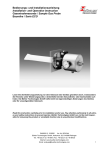
Bedienungs- und Installationsanleitung
Installation- and Operation Instruction
Gasentnahmesonde / Sample Gas Probe
Baureihe / Serie ECO
Lesen Sie die Bedienungsanleitung vor dem Gebrauch des Gerätes gründlich durch, insbesondere
die Hinweise unter Gliederungspunkt 2. Andernfalls könnten Gesundheits- oder Sachschäden auftreten. Die Bühler Technologies GmbH haftet nicht bei eigenmächtigen Änderungen des Gerätes
oder für unsachgemäßen Gebrauch.
Read this instruction carefully prior to installation and/or use. Pay attention particularly to all advises and safety instructions to prevent injuries. Bühler Technologies GmbH can not be held responsible for misusing the product or unreliable function due to unauthorised modifications.
BX460013, 12/2006
Art. Nr. 9031044
Bühler Technologies GmbH, Harkortstr. 29, D-40880 Ratingen,
Tel. +49 (0) 21 02 / 49 89-0, Fax. +49 (0) 21 02 / 49 89-20
Email: [email protected]
1
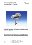
Bedienungs- und Installationsanleitung
Installation- and Operation Instruction
Gasentnahmesonde / Sample Gas Probe
Baureihe / Serie ECO
Inhaltsverzeichnis
1
2
3
4
5
6
7
8
9
Seite
Einleitung................................................................................................................................................ 3
Wichtige Hinweise ................................................................................................................................. 3
Transport und Lagerungsvorschriften ................................................................................................ 5
Aufbauen und Anschließen .................................................................................................................. 5
4.1 Montage ........................................................................................................................................... 5
4.2 Anschluss der Gasleitungen ............................................................................................................ 5
4.3 Elektrische Anschlüsse .................................................................................................................... 6
Betrieb und Wartung ............................................................................................................................. 7
5.1 Warnhinweise................................................................................................................................... 7
5.2 Betrieb .............................................................................................................................................. 7
5.3 Rückspülung des Eintrittsfilters ........................................................................................................ 8
5.4 Wartung............................................................................................................................................ 8
Fehlersuche und Beseitigung .............................................................................................................. 9
Instandsetzung und Entsorgung.......................................................................................................... 9
7.1 Entsorgung ....................................................................................................................................... 9
Ersatzteile .............................................................................................................................................10
Beiliegende Unterlagen .......................................................................................................................10
Contents
1
2
3
4
5
6
7
8
9
2
page
Introduction ..........................................................................................................................................11
Important advices ................................................................................................................................11
Transport and storing regulations .....................................................................................................12
Installation and connection ................................................................................................................13
4.1 Mounting.........................................................................................................................................13
4.2 Connecting the sample tube ..........................................................................................................13
4.3 Electrical connections ....................................................................................................................13
Operation and Maintenance................................................................................................................14
5.1 Indication of risk .............................................................................................................................14
5.2 Operation and maintenance...........................................................................................................15
5.3 Blow back .......................................................................................................................................15
5.4 Maintenance...................................................................................................................................16
Trouble shooting and elimination ......................................................................................................16
Repair and disposal.............................................................................................................................17
7.1 Disposal..........................................................................................................................................17
Spare parts ...........................................................................................................................................17
Attached documents ...........................................................................................................................17
BX460013, 12/2006
Art. Nr. 9031044
Bedienungs- und Installationsanleitung
Installation- and Operation Instruction
Gasentnahmesonde / Sample Gas Probe
Baureihe / Serie ECO
1
Einleitung
Die Gasentnahmesonde der Baureihe ECO ist zum Einbau in Gasanalysesystemen bestimmt. Gasentnahmesonden gehören zu den wichtigsten Bauteilen eines Gasaufbereitungssystems. Bitte beachten Sie
deshalb auch das dazugehörige Datenblatt am Ende dieser Anleitung und überprüfen Sie vor Einbau der
Gasentnahmesonden, ob die genannten technischen Daten den Anwendungsparametern entsprechen.
Überprüfen Sie ebenfalls, ob alle zum Lieferumfang gehörenden Teile vollständig vorhanden sind.
Bitte beachten Sie beim Anschluss die Kennwerte der Sonde und bei Ersatzteilbestellungen die richtigen
Ausführungen
2
Wichtige Hinweise
Der Einsatz der Geräte ist nur zulässig, wenn:
−
das Produkt unter den in der Bedienungs- und Installationsanleitung beschriebenen Bedingungen, dem
Einsatz gemäß Typenschild und für Anwendungen, für die es vorgesehen ist, verwendet wird.
−
die im Datenblatt und der Anleitung angegebenen Grenzwerte eingehalten werden.
−
Überwachungsvorrichtungen/ Schutzvorrichtung korrekt angeschlossen sind.
−
die Service- und Reparaturarbeiten, die nicht in dieser Anleitung beschrieben sind, von Bühler Technologies GmbH durchgeführt werden.
− Originalersatzteile verwendet werden.
Diese Bedienungsanleitung ist Teil des Betriebsmittels. Der Hersteller behält sich das Recht vor, die
Leistungs-, die Spezifikations- oder die Auslegungsdaten ohne Vorankündigung zu ändern. Bewahren Sie
die Anleitung für den späteren Gebrauch auf.
Beachten Sie unbedingt die für den Einbauort relevanten Sicherheitsvorschriften und allgemeinen gültigen
Regeln der Technik.
Begriffsbestimmungen für Warnhinweise:
HINWEIS
Signalwort für wichtige Information zum Produkt auf die im besonderen Maße
aufmerksam gemacht werden soll.
VORSICHT
Signalwort zur Kennzeichnung einer Gefährdung mit geringem Risiko, die zu einem
Sachschaden oder leichten bis mittelschweren Körperverletzungen führen kann, wenn
sie nicht vermieden wird.
WARNUNG
Signalwort zur Kennzeichnung einer Gefährdung mit mittlerem Risiko, die
möglicherweise Tod oder schwere Körperverletzungen zur folge hat, wenn sie nicht
vermieden wird.
GEFAHR
Signalwort zur Kennzeichnung einer Gefährdung mit hohem Risiko, die unmittelbar Tod
oder schwere Körperverletzung zur folge hat, wenn sie nicht vermieden wird.
Warnung vor einer allgemeinen Gefahr
Warnung vor explosionsgefährdeten Bereichen
Netzstecker ziehen
Warnung vor elektrischer
Spannung
Warnung vor heißer Oberfläche
Atemschutz tragen
Warnung vor dem Einatmen giftiger Gase
Gesichtsschutz
tragen
Warnung vor ätzenden
Flüssigkeiten
Handschuhe tragen
BX460013, 12/2006
Art. Nr. 9031044
3
Bedienungs- und Installationsanleitung
Installation- and Operation Instruction
Gasentnahmesonde / Sample Gas Probe
Baureihe / Serie ECO
Das Gerät darf nur von Fachpersonal installiert werden, das mit den Sicherheitsanforderungen und den
Risiken vertraut ist.
Beachten Sie unbedingt die für den Einbauort relevanten Sicherheitsvorschriften und allgemein gültigen
Regeln der Technik. Beugen Sie Störungen vor und vermeiden Sie dadurch Personen- und Sachschäden.
Der für die Anlage Verantwortliche muss sicherstellen, dass:
−
Sicherheitshinweise und Betriebsanleitungen verfügbar sind und eingehalten werden,
−
Unfallverhütungsvorschriften der Berufsgenossenschaften beachtet werden; in Deutschland:
Allgemeine Vorschriften” (VBG 1) und “Elektrische Anlagen und Betriebsmittel (VBG 4)”,
−
die zulässigen Daten und Einsatzbedingungen eingehalten werden,
−
Schutzeinrichtungen verwendet werden und vorgeschriebene Wartungsarbeiten durchgeführt werden,
−
bei der Entsorgung die gesetzlichen Regelungen beachtet werden.
Wartung, Reparatur:
−
Reparaturen an den Betriebsmitteln dürfen nur von Bühler autorisiertem Personal ausgeführt werden.
−
Nur Umbau-, Wartungs- oder Montagearbeiten ausführen, die in dieser Bedienungs- und Installationsanleitung beschrieben sind.
−
Nur Original-Ersatzteile verwenden.
Bei Durchführung von Wartungsarbeiten jeglicher Art müssen die relevanten Sicherheits- und
Betriebsbestimmungen beachtet werden.
GEFAHR
Elektrische Spannung
Gefahr eines elektrischen Schlages.
Trennen Sie das Gerät bei allen Arbeiten vom Netz. Sichern Sie das Gerät
gegen unbeabsichtigtes Wiedereinschalten.
Das Gerät darf nur von instruiertem, fachkundigem Personal geöffnet werden.
GEFAHR
Giftige, ätzende Gase
Messgas kann gesundheitsgefährdend sein.
Sorgen Sie ggf. für eine sichere Ableitung des Gases.
Stellen Sie vor Beginn der Wartungsarbeiten die Gaszufuhr ab und sichern Sie
sie gegen unbeabsichtigtes Aufdrehen.
Schützen Sie sich bei der Wartung vor giftigen / ätzenden Gasen. Tragen Sie
die entsprechende Schutzausrüstung.
GEFAHR
Explosionsgefahr bei Verwendung in Explosionsgefährdeten Bereichen
Das Betriebsmittel ist nicht für den Einsatz in explosionsgefährdeten Bereichen
geeignet.
Durch das Gerät dürfen keine zündfähigen oder explosiven Gasgemische
geleitet werden.
4
BX460013, 12/2006
Art. Nr. 9031044
Bedienungs- und Installationsanleitung
Installation- and Operation Instruction
Gasentnahmesonde / Sample Gas Probe
Baureihe / Serie ECO
3
Transport und Lagerungsvorschriften
Die Gasentnahmesonde nur in der Originalverpackung oder einem geeigneten Ersatz transportieren.
Bei längerer Nichtbenutzung ist die Gasentnahmesonde gegen Feuchtigkeit und Wärme zu schützen.
Die Gasentnahmesonde muss in einem überdachten, trockenen, vibrations- und staubfreien Raum bei
einer Temperatur von –20°C bis +50°C aufbewahrt werden.
4
4.1
Aufbauen und Anschließen
Montage
Die Gasentnahmesonden sind zur Flanschmontage vorgesehen. Einbauort und Einbaulage bestimmen
sich aus anwendungsrelevanten Voraussetzungen. Falls möglich, sollte der Einbaustutzen eine leichte
Neigung zur Kanalmitte haben. Der Einbauort sollte wettergeschützt sein.
Ebenfalls muss auf ausreichenden und sicheren Zugang sowohl für die Installation als auch für spätere
Wartungsarbeiten geachtet werden. Beachten Sie hier insbesondere die Ausbaulänge des Sondenrohres!
Soweit die Sonde in Einzelteilen zum Einbauort gebracht wird, muss sie zunächst zusammengebaut werden. Bei dem Entnahmerohr 03 (gesinterter Edelstahlfilter) wird dieser lediglich angeschraubt.
Die Entnahmerohre 10 und 11 werden eingeschraubt. Dann wird die Filtertüte übergezogen und mit der
Schelle flanschseitig gesichert.
Am Druckluftbehälter befinden sich am Umfang zwei Muffen mit G ¼“ Innengewinden. Eine dieser Muffen
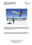
wird für den Ablass von Kondensat benötigt und muss nach unten zeigen. Die andere kann für den Anschluss eines Manometers genutzt werden (siehe Photo auf der 1. Seite, nicht im Lieferumfang). Nichtbenutzte Muffen müssen mit einem Stopfen abgedichtet werden.
Um die Einbaulage der Sonde frei bestimmbar zu machen, kann der Druckluftbehälter gedreht werden.
Dazu drehen Sie den Stopfen des Druckluftanschlusses an der Rückseite (Zeichnung siehe Datenblatt)
heraus. Man sieht nun die Sechskantmutter in der Öffnung. Lösen Sie diese, ziehen Sie den Druckluftbehälter von der Sonde weg und drehen Sie ihn in die gewünschte Richtung. Achten Sie darauf, dass eine
Muffe auf dem Umfang für das Ablassen von Kondensat nach unten zeigt. Ziehen Sie die Mutter nun wieder an und schrauben Sie den Stopfen wieder fest ein.
Danach wird die Sonde unter Verwendung der beigefügten Dichtungen und Schrauben am Gegenflansch
befestigt.
Bei warmen Anwendungen sollten die blank liegenden Flanschteile und ggf. der Einbaustutzen nach der
Montage isoliert werden, damit Kältebrücken unbedingt vermieden werden. Das Isoliermaterial muss den
Anwendungsvoraussetzungen entsprechen und wetterfest sein.
4.2
Anschluss der Gasleitungen
Die Messgasleitung ist mittels einer geeigneten Verschraubung (NPT ¼“) sorgfältig und fachgerecht anzuschließen. Dies gilt auch für den Prüfgasanschluss. Wird letzterer nicht benutzt, so ist er mit einem Stopfen
zu verschließen.
Soll bei Ihrer Anwendung Kondensation in der Leitung vermieden werden, ist diese zu beheizen. Die Verschraubung und die Sonde sind dann zu isolieren.
!
!
WARNUNG
Gasaustritt
Prüfen Sie die Leitungen auf Dichtheit.
BX460013, 12/2006
Art. Nr. 9031044
5
Bedienungs- und Installationsanleitung
Installation- and Operation Instruction
Gasentnahmesonde / Sample Gas Probe
Baureihe / Serie ECO
4.3
Elektrische Anschlüsse
WARNUNG
Der Anschluss darf nur von geschultem Fachpersonal vorgenommen werden.
VORSICHT
Falsche Netzspannung kann das Gerät zerstören
Die Spannungsversorgung betrögt 24 VDC.
Das Gerät ist mit einem Stecker nach DIN 43650 für ausgestattet. Nachfolgend sind die Anschlussbelegungen und die Zuordnung der Magnetventile zur Funktion angegeben. Die angegebenen Nummern entsprechen denen auf den Steckern.
Die Spannungsversorgung beträgt 24 VDC
M3
Rückspülung /
Blow back
PE
1
2
3
1
2
Meßgas /
Sample
3
PE
A000092X
WARNUNG
Beschädigung des Gerätes bei Durchführung der Isolationsprüfung
Führen Sie keine Prüfung der Spannungsfestigkeit mit Hochspannung
am Gesamtgerät durch!
Das Gerät ist mit umfangreichen EMV-Schutzmaßnahmen ausgerüstet. Bei einer Prüfung der Spannungsfestigkeit werden elektronische Filterbauteile beschädigt. Die notwendigen Prüfungen wurden bei allen zu
prüfenden Baugruppen werkseitig durchgeführt (Prüfspannung je nach Bauteil 1 kV bzw. 1,5 kV).
Sofern Sie die Spannungsfestigkeit selbst nochmals prüfen wollen, führen Sie diese nur an den entsprechenden Einzelkomponenten durch.
Klemmen Sie die Heizung der Sonde bzw. des Gasdruckbehälters ab und stecken Sie die Versorgung der
Magnetventile aus (siehe Anschlussbelegung im Anhang). Führen Sie nun die Spannungsfestigkeitsprüfung gegen Erde durch.
6
BX460013, 12/2006
Art. Nr. 9031044
Bedienungs- und Installationsanleitung
Installation- and Operation Instruction
Gasentnahmesonde / Sample Gas Probe
Baureihe / Serie ECO
5
5.1
Betrieb und Wartung
Warnhinweise
−
Die Gasentnahmesonde darf nicht außerhalb ihrer Spezifikationen betrieben werden.
−
Reparaturen an den Betriebsmitteln dürfen nur von Bühler autorisiertem Personal ausgeführt werden.
−
Führen Sie nur Umbau-, Wartungs- oder Montagearbeiten aus, die in dieser Bedienungs- und Installationsanleitung beschrieben sind.
−
Verwenden Sie nur Original-Ersatzteile.
−
Beachten Sie bei der Durchführung von Wartungsarbeiten jeglicher Art die relevanten Sicherheits- und
Betriebsbestimmungen.
GEFAHR
Elektrische Spannung
Gefahr eines elektrischen Schlages.
Trennen Sie das Gerät bei allen Wartungsarbeiten vom Netz. Sichern Sie das
Gerät gegen unbeabsichtigtes Wiedereinschalten.
Der Anschluss darf nur von geschultem Fachpersonal vorgenommen werden.
Achten Sie auf die korrekte Spannungsversorgung!
GEFAHR
Giftige, ätzende Gase
Messgas kann gesundheitsgefährdend sein.
Stellen Sie vor Beginn der Wartungsarbeiten die Gaszufuhr ab und spülen Sie
die Gasleitungen ggf. mit Luft.
Bitte sorgen Sie ggf. für eine sichere Ableitung des Gases.
Schützen Sie sich bei der Wartung vor giftigen / ätzenden Gasen. Tragen Sie
die entsprechende Schutzausrüstung.
!
VORSICHT
Heiße Oberfläche
Verbrennungsgefahr
Lassen Sie das Gerät erst abkühlen, bevor Sie mit den Wartungsarbeiten
beginnen.
5.2
Betrieb
Kontrollieren Sie vor Inbetriebnahme,
−
die Schlauch- und Elektroanschlüsse auf Nichtbeschädigung und korrekte Montage.
−
dass keine Teile der Gasentnahmesonde demontiert sind.
−
dass die Schutz- und Überwachungsvorrichtungen vorhanden und funktionsfähig sind.
−
dass der Gas Ein- und Ausgang der Gasentnahmesonde nicht zugesperrt ist.
BX460013, 12/2006
Art. Nr. 9031044
7
Bedienungs- und Installationsanleitung
Installation- and Operation Instruction
Gasentnahmesonde / Sample Gas Probe
Baureihe / Serie ECO
−
dass die Umgebungsparameter eingehalten werden.
−
dass die Leistungsangaben auf dem Typenschild eingehalten werden.
−
ob Spannung und Frequenz auf dem Typenschild mit den Netzwerten übereinstimmen.
−
ob alle Anschlusskabel zugentlastet montiert sind.
−
ob Schutzmaßnahmen durchgeführt sind (Erdung).
− ob Leitungseinführung sachgemäß abgedichtet ist.
Die Sonden sind mit einem Eintrittsfilter ausgerüstet, welcher sich permanent im Prozessstrom befindet.
Dieser Filter lässt sich mittels Druckluft rückspülen, d.h. die Luft wird von innen nach außen durch den
Filter geblasen und löst so die anhaftenden Partikel ab.
5.3
Rückspülung des Eintrittsfilters
Bitte beachten sie, dass zum Rückspülen gefilterte Luft mindestens nach PNEUROP / ISO Klasse 4 verwendet wird:
Klasse
4
Partikel/ m3
Drucktaupunkt
Restölgehalt
Partikelgröße: (1 bis 5) µm
[°C]
[mg/m3]
≤3
≤5
bis 1000
(keine Partikel ≥ 15µm)
In der Steuerung des Systems ist eine sequentielle Ansteuerung der Ventile vorzusehen, d.h.:
1. Absperren des Magnetventils für den Messgasausgang.
2. Danach Öffnen des Magnetventils zwischen Druckluftbehälter und Sonde für ca. 10 Sekunden
3. Magnetventil für den Messgasausgang wieder öffnen.
Zwischen dem Schließen des einen und dem Öffnen des anderen Magnetventils muss eine Verzögerungszeit vorgesehen werden, um Druckstöße in der Messgasleitung zu vermeiden.
Die Rückspülung kann auch als geschlossener Vorgang in Zeitintervallen von sowohl einigen Minuten bis
Stunden als auch Tagen je nach Bedarf eingestellt werden. Hierzu bieten wir eine Rückspülsteuerung Typ
RSS 24 an.
5.4
Wartung
Die Sonden arbeiten bei ausreichender Rückspülung des Eintrittsfilters wartungsfrei. Dennoch kann es
aufgrund der Prozessbedingungen zum allmählichen Zusetzen des Filterelementes kommen. Sollte dies
der Fall sein, muss das Filterelement ausgewechselt werden. Hierzu muss die Sonde vollständig ausgebaut und nach Wechsel des Elementes wie in Kapitel 4 beschrieben wieder installiert werden.
Für den Wechsel der Filtertüten lösen Sie die Schelle, ziehen den alten Filter ab und montieren den neuen
in umgekehrter Reihenfolge.
Achtung! Bei Prozesstemperaturen über 135°C muss dies eine Filtertüte aus PTFE sein.
Der Edelstahlfilter wird abgeschraubt und durch den neuen ersetzt. Gegebenenfalls kann der Filter auch in
einem Ultraschallbad gereinigt werden.
Je nach Aufstellungsort und Applikationsbedingungen kann es im Druckluftbehälter für die Rückspülluft zu
leichter Kondensatbildung kommen. Es ist daher empfehlenswert mindestens einmal jährlich die Ablassschraube am Boden des Behälters zu öffnen und das Kondensat abzulassen.
Sollte aufgrund der Betriebsverhältnisse ein häufiges Warten der Sonden erforderlich sein, empfehlen wir
im Zuge dieser Intervalle auch das Kondensat zu entleeren.
8
BX460013, 12/2006
Art. Nr. 9031044
Bedienungs- und Installationsanleitung
Installation- and Operation Instruction
Gasentnahmesonde / Sample Gas Probe
Baureihe / Serie ECO
6
Fehlersuche und Beseitigung
!
!
VORSICHT
Risiko durch fehlerhaftes Gerät
Personen- oder Sachschäden möglich
Beheben Sie Störungen am Gerät umgehend. Schalten Sie das Gerät aus und
trennen Sie es vom Netz.
Problem / Störung
Kein bzw. verminderter
Gasfluss
7
mögliche Ursache
Abhilfe
−
Filterelement verstopft
−
Filterelement reinigen bzw. austauschen
−
Magnetventil geschlossen
−
Magnetventil öffnen
−
Rückspülung ohne Funktion
−
Druckluftnetz überprüfen, Magnetventil überprüfen
Instandsetzung und Entsorgung
Sollte ein Fehler beim Betrieb auftreten, finden Sie unter Gliederungspunkt 6. Hinweise für die Fehlersuche
und Beseitigung.
Sollten Sie weitere Fragen haben, wenden Sie sich bitte an unseren Service
Tel.: +49-(0)2102-498955 oder Ihre zuständige Vertretung.
Ist nach Beseitigung eventueller Störungen und nach Einschalten der Netzspannung die korrekte Funktion
nicht gegeben, muss das Gerät durch den Hersteller überprüft werden. Bitte senden Sie das Gerät zu diesem Zweck in geeigneter Verpackung an:
Bühler Technologies GmbH
- Reparatur/Service Harkortstraße 29
40880 Ratingen
Deutschland
7.1
Entsorgung
Bei der Entsorgung sind die gesetzlichen Vorschriften, insbesondere für die Entsorgung von elektronischen
Bauteilen, zu beachten.
BX460013, 12/2006
Art. Nr. 9031044
9
Bedienungs- und Installationsanleitung
Installation- and Operation Instruction
Gasentnahmesonde / Sample Gas Probe
Baureihe / Serie ECO
8
Ersatzteile
Bei Ersatzteilbestellungen bitten wir Sie, Gerätetyp und Seriennummer anzugeben.
Bauteile für Nachrüstung und Erweiterung finden Sie im angehängten Datenblatt und in unserem Katalog.
Die folgenden Ersatzteile sollten vorgehalten werden:
Ersatzteil
Artikel-Nr.
Flanschdichtung Typ 222.
90 09 079
Dichtung für Sondenrohr Typ 222.
90 09 068
Ersatzfilter bis 135 °C, Polyester
46 222 0071
Ersatzfilter bis 260 °C, PTFE
46 222 0072
O-Ring für Druckluftbehälter
90 09 081
Cu-Dichtring für Druckluftbehälter
90 09 053
9
Beiliegende Unterlagen
Am Ende dieser Anleitung sind folgende Dokumente angehängt:
−
Datenblatt:
DD460003, DE460003, DA460003
−
Konformitätserklärung:
KX460003
10
BX460013, 12/2006
Art. Nr. 9031044
Bedienungs- und Installationsanleitung
Installation- and Operation Instruction
Gasentnahmesonde / Sample Gas Probe
Baureihe / Serie ECO
1
Introduction
The sample gas probe series ECO is designed for installation in gas analysing systems.
Sample gas probes are very important components in a sample conditioning system. Hence it is essential
to read this manual carefully and check that all application parameters are completely matched by the selected gas probe (see corresponding drawing in the data sheet attached). In addition check also the shipment and make sure you have received all parts.
Regard the specific limits of the gas probe. Please only order the spare parts which matching the probe
type.
2
Important advices
Operation of the device is only valid if
−
the product is used under the conditions described in the installation- and operation instruction, the
intended application according to the type plate and the intended use,
−
the performance limits given in the datasheets and in the installation- and operation instruction are
obeyed,
−
monitoring devices and safety devices are installed properly,
−
service and repair is carried out by Bühler Technologies GmbH, unless described in this manual,
− only original spare parts are used.
This manual is part of the equipment. The manufacturer keeps the right to modify specifications without
advanced notice. Keep this manual for later use...
Definitions for warnings:
NOTE
Signal word for important information to the product.
CAUTION
Signal word for a hazardous situation with low risk, resulting in damaged to the device or
the property or minor or medium injuries if not avoided.
WARNING
Signal word for a hazardous situation with medium risk, possibly resulting in severe
injuries or death if not avoided.
DANGER
Signal word for an imminent danger with high risk, resulting in severe injuries or death if
not avoided.
Warning against hazardous situation
Warning against possible
explosive atmospheres
disconnect from
mains
Warning against electrical voltage
Warning against hot surface
wear respirator
Warning against respiration of toxic gases
wear face protection
Warning against acid
and corrosive substances
wear gloves
Installation of the device shall be performed by trained staff only, familiar with the safety requirements and
risks.
Check all relevant safety regulations and technical indications for the specific installation place. Prevent
failures and protect persons against injuries and the device against damage.
BX460013, 12/2006
Art. Nr. 9031044
11
Bedienungs- und Installationsanleitung
Installation- and Operation Instruction
Gasentnahmesonde / Sample Gas Probe
Baureihe / Serie ECO
The person responsible for the system must secure that:
−
safety and operation instructions are accessible and followed,
−
local safety regulations and standards are obeyed,
−
performance data and installation specifications are regarded,
−
safety devices are installed and recommended maintenance is performed,
−
national regulations for disposal of electrical equipment are obeyed.
Maintenance and repair
−
Repairs on the device must be carried out by Bühler authorized persons only.
−
Only perform modifications, maintenance or mounting described in this manual.
− Only use original spare parts.
During maintenance regard all safety regulations and internal operation instructions.
DANGER
Electrical voltage
Electrocution hazard.
Disconnect the device from power supply. Make sure that the equipment
cannot be reconnected to mains unintentionally.
The device must be opened by trained staff only.
DANGER
Toxic and corrosive gases
Sample gas can be hazardous.
Take care that the gas is exhausted in a place where no persons are in danger.
Before maintenance turn off the gas supply and make sure that it cannot be
turned on unintentionally.
Protect yourself during maintenance against toxic / corrosive gases. Use
gloves, respirator and face protector under certain circumstances.
DANGER
Explosion hazard if used in hazardous areas
The device is not suitable for operation in hazardous areas with potentially
explosive atmospheres.
Do not expose the device to combustible or explosive gas mixtures.
3
Transport and storing regulations
The sample gas probe should be only transported in the original case or in appropriate packing.
Protect the sample gas probe against heat and humidity.
The sample gas probe must be stored in roofed, dry, vibration- und dust free room. Temperature should be
between –20°C / -4°F and +50°C /122°F.
12
BX460013, 12/2006
Art. Nr. 9031044
Bedienungs- und Installationsanleitung
Installation- and Operation Instruction
Gasentnahmesonde / Sample Gas Probe
Baureihe / Serie ECO
4
4.1
Installation and connection
Mounting
The sample gas probes are provided with a mounting flange. The installation site and the installation position depend on the application. Whenever possible the extension tube should point slightly downward. The
place of installation should be weather shielded.
Make sure that the access to the installation site is safe and free, also for maintenance carried out later
and that there is enough space to take out the probe even with the extension tube attached.
In case that the sample gas probe is transported in parts to the installation site, the probe has to be assembled first.
The extension 03 (sintered stainless steel) has to be screwed in.
The extensions 10 and 11 are screwed in. Then the filter hose is fitted and secured with the clamp near the
flange.
At the perimeter of the blowback vessel are two inner threads G ¼“. One of these threads is used for condensate draining and has to point downwards. The other thread may be used for a pressure gauge (see
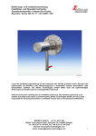
photograph, not part of delivery). Unused threads have to be plugged safely.
The blowback vessel can be turned to make the direction of mounting versatile. To turn the vessel, unscrew the air inlet plug on the plain side (see drawing in data sheet). Inside you now can see the hexagon
nut. Unscrew it, take the pressure vessel carefully a bit away from the probe and turn it into the wanted
direction. Remember that one of the threads on the perimeter has to point downwards. Tighten the nut and
screw in the plug tightly.
At last the probe is mounted using appropriate screws and sealings.
For warm applications all metal parts exposed to ambient must be fully insulated after the probe has been
installed properly. This is necessary to avoid cold spots. The type of insulation must be suitable for the
particular application and be weather proof.
4.2
Connecting the sample tube
The sample tube must be connected with an appropriate fitting (NPT ¼“). This is as well for the optional
calibration port. If the calibration port is not used, it has to be closed with a plug.
!
!
4.3
WARNING
Gas leakage
Check the tightness of all tubes.
Electrical connections
WARNING
The device must be installed by trained staff only.
CAUTION
Wrong mains voltage may damage the device.
Regard the correct mains voltage as given on the type plate.
BX460013, 12/2006
Art. Nr. 9031044
13
Bedienungs- und Installationsanleitung
Installation- and Operation Instruction
Gasentnahmesonde / Sample Gas Probe
Baureihe / Serie ECO
The solenoid valves are equipped with two connectors according to DIN 43650. The power supply is 24V
DC. The wiring and positions of the solenoid valves are found in the drawing below.
M3
Rückspülung /
Blow back
PE
1
2
3
1
2
Meßgas /
Sample
3
PE
A000092X
WARNING
Damage to the device in case of insulation testing
Do not proceed insulation tests with high voltage to the device as a whole.
The device is equipped with extensive EMC protection. If insulation tests are carried out the electronic filter
devices will be damaged. All necessary tests have been carried out for all concerned groups of components at the factory (test voltage 1 kV or 1.5 kV respectively, depending on the device).
If you wish to carry out the insulation test by yourself, please test only separate groups of components.
Disconnect the heating of the probe or of the pressure vessel and pull off the supply of the solenoid valves
(see wiring diagram attached). Then carry out the insulation tests.
5
5.1
−
−
−
−
−
Operation and Maintenance
Indication of risk
The device must be operated within its specifications.
All repairs must be carried out by Bühler authorised personnel only.
Only perform modifications, servicing or mounting described in this manual.
Only use original spare parts.
Regard all relevant safety regulations and internal operating instructions during maintenance.
DANGER
Electrical voltage
Electrocution hazard.
Before any manipulation on the device, disconnect the electrical equipment
from mains power supply. Make sure that the electrical equipment cannot
be reconnected during repair or maintenance.
The wiring must be done by trained staff only. Regard the correct mains
voltage.
14
BX460013, 12/2006
Art. Nr. 9031044
Bedienungs- und Installationsanleitung
Installation- and Operation Instruction
Gasentnahmesonde / Sample Gas Probe
Baureihe / Serie ECO
DANGER
Toxic, corrosive gases
Sample gas may be harmful.
Before maintenance turn off the gas supply and make sure that it cannot be
turned on unintentionally.
Please exhaust sample gas to a safe place.
Protect yourself against toxic / corrosive gas during maintenance. Use
gloves, respirator and face protector under certain circumstances.
!
CAUTION
Hot surface
Hazard of burning
Let the device cool down before maintaining.
5.2
Operation and maintenance
Please check
−
all tubes and electric fittings, make sure there are no damages and mounting is correct.
−
that no part of the sample gas probe is demounted (e.g. cover).
−
whether the protective and surveillance devices are installed and functioning.
−
whether the inlet and outlet tubes of the sample gas probe are not closed.
−
whether the ambient parameters are not exceeded.
−
that power data comply with the data on the rating plate!
−
whether all electrical connections are tightened; check if the monitoring equipment is properly connected and set!
− whether equipment is grounded and duly protected!
The probes have an in-situ filter.
This filter can be cleaned by a blow back with plant air i.e. the pressurized air is blown from inside to outside and back washes the filter element.
5.3
Blow back
Plant air (inert gas) must be dry and free from particles. Please use filtered air (inert gas) subject to the
PNEUROP / ISO class 4
Class
4
[Particles/m3 ] / [paticles/ft³]
Pressure dew point
Oil content
particle size:
(1 up to 5) µm / (39.4 up to 197)⋅10-6in
[°C] / [°F]
[mg/m³] / [lb/ft³]
up to 1000 / up to 28
≤ 3 / ≤ 37
≤ 5 / ≤ 0.312⋅10-6
( no particles ≥ 15µm / 591⋅10-6in)
BX460013, 12/2006
Art. Nr. 9031044
15
Bedienungs- und Installationsanleitung
Installation- and Operation Instruction
Gasentnahmesonde / Sample Gas Probe
Baureihe / Serie ECO
The control circuit of the main system provides the electrical contacts to reassure the following steps:
1. Close sample gas solenoid valve.
2. Open solenoid valve between capacity tank and probe for about 10 seconds.
3. Open sample gas solenoid valve again.
Between closing the one solenoid valve and opening the other, there should be a short delay to prevent the
analyzer line from getting pressure shocks.
The blow back procedure can also be carried out in time sequences i.e. close probe valve and open solenoid valve for 10 seconds – blow back – open probe valve every few minutes, hours or days depending on
dust load in process. A blowback controller type RSS 24 is available for that.
5.4
Maintenance
Normally these probes are free of maintenance. However it may happen due to process conditions that the
upstream filter clogs up after a certain time. In this case the filter has to be replaced. Therefore the probe
must be completely dismounted and after changing the filter be installed again as described in chapter 4.
For exchange of the filter hose, disassemble the clamp, take off the old hose and assemble the new one in
reverse order.
Be careful! With temperatures in the process of more than 135°C (275°F) the filter hose material has to be
PTFE.
The sintered stainless steel filter is unscrewed and replaced by a new one. This filter can be cleaned in an
ultrasonic bath and be used several times. A new seal for the probe type has to be fitted.
Depending on the ambient conditions, formation of condensate may occur in the capacity tank. We recommend, at least once a year, or if the application requires a more frequent regular maintenance, to drain
the capacity tank by opening the outlet on the bottom using an Allen key.
6
Trouble shooting and elimination
!
!
CAUTION
Risk due to defective device
Personal injury or damage to property
In case of failure switch off the device immediately and it should not be
turned on again before elimination of the failure.
Problem / Failure
No or reduced gas flow
16
Possible cause
Solution
−
filter element clogged
−
clean or replace filter element
−
valve shut
−
open valve
−
blow back not efficient
−
if plant air available try with full
pressure and flow; check solenoid valve
BX460013, 12/2006
Art. Nr. 9031044
Bedienungs- und Installationsanleitung
Installation- and Operation Instruction
Gasentnahmesonde / Sample Gas Probe
Baureihe / Serie ECO
7
Repair and disposal
If the device shows irregularities see chapter 6 for troubleshooting
If you need help or more information
call +49(0)2102-498955 or your local agent.
If the device doesn’t work correctly after elimination of failures and turning power on, the device must be
checked by the manufacturer. Please ship the device with suitable packing to
Bühler Technologies GmbH
- Service Harkortstraße 29
40880 Ratingen
Germany
7.1
Disposal
The corresponding laws and regulations of your country must be followed by disposal.
8
Spare parts
To order spare parts please indicate type of device and serial no. For accessories and enhancement see
data sheets and/or catalogue.
The following parts are recommended for stocking:
Spare part
Part no.
Gasket type 222.
90 09 079
Seal for probe pipe type 222.
90 09 068
Filter element, up to 135°C (275°F), Polyester
46 222 0071
Filter element, up to 260°C (500°F), PTFE
46 222 0072
O-ring for pressure vessel
90 09 081
Copper seal for pressure vessel
90 09 053
9
Attached documents
−
data sheet:
DE460003, DA460003
−
declaration of conformity:
KX460003
BX460013, 12/2006
Art. Nr. 9031044
17
EU-Konformitätserklärung gemäß EN 45014
EU-declaration of conformity according to EN 45014
Hiermit erklären wir, dass die nachfolgenden Produkte den wesentlichen Anforderungen
der folgenden Richtlinien in ihrer aktuellen Fassung entsprechen:
-
Richtlinie 73/23/EWG über elektrische Betriebsmittel zur Verwendung innerhalb
bestimmter Spannungsgrenzen
Richtlinie 89 / 336 / EWG über die elektromagnetische Verträglichkeit
Richtlinie 97 / 23 / EG über Druckgeräte
Herewith we declare that the following products correspond to the essential requirements of
- Directive 73 / 23 EWG about electrical equipment for use with certain limits of voltage,
- Directive 89 / 336 / EWG about electromagnetic compatibility,
- Directive 97 / 23 / EG about pressure equipment
Produkte / products
Gasentnahmesonden
(Sample gas probes)
ECO
(Typ, type),
Zur Beurteilung der Konformität wurden folgende harmonisierte Normen herangezogen:
The following harmonized standards have been used:
• EN 61000-6-3 (2001) - Elektromagnetische Vertäglichkeit- Fachgrundnorm Störaussendung
(Wohnbereich,Geschäfts und Gewerbebereich, Kleinbetriebe)
• EN 61000-6-2 (2001) - Elektromagnetische Störfestigkeit- Fachgrundnorm Störfestigkeit
(Industriebereich, 2001)
• EN 60204 –1 (1997) - Sicherheit von Maschinen - elektrische Ausrüstung von Maschinen –
Teil1: Allgemeine Anforderungen
Ratingen, den 04. Oktober 2004
________________________
G.R. Biller
Geschäftsführer – Managing Director
KX 46 0003
__________________________________
Stefan Eschweiler
Technischer Leiter – technical manager
Datum
Bühler Mess- und Regeltechnik GmbH, Harkortstr. 29, D-40880 Ratingen,
Tel. +49 (0) 21 02 / 49 89-0, Fax. +49 (0) 21 02 / 49 89-20
Email: [email protected]
®
Gasentnahmesonde ECO
Der traditionelle Aufbau von Gasentnahmesonden entspricht weitestgehend den VDI/VDE-Richtlinien 3516 aus
dem Jahre 1978. Aufgrund des zwischenzeitlich erreichten
Fortschritts, besonders in der Staubfiltration, verfügen wir
heute über technische Lösungen, die den traditionellen
Ausführungen erheblich überlegen sind.
Insbesondere für Anwendungen in Applikationen mit
niedrigen Temperaturen, aber mittleren bis hohen Staubbelastungen, lassen sich unter Verwendung der neu entwickelten ECO-Sonde besonders die Wartungskosten für
die Filter erheblich reduzieren.
Gleichzeitig wurde aber auch auf eine einfache, kompakte
Konstruktion geachtet, damit die Anschaffungs- und
Installationskosten gering bleiben.
Kernstück der ECO-Sonde ist der Sondenkörper, der sowohl die zur Rückspülung des Filterelementes nötigen
Magnetventile trägt, als auch den zur Effizienzerhöhung der
Rückspülung nötigen Vorratsbehälter für die Druckluft.
Der Vorratsbehälter hat an der Seite zwei Anschluß-muffen,
die zum Anschluß eines Manometers bzw. als
Kondensatablaß genutzt werden können. Der Behälter ist
über eine Zentralschraube befestigt und kann bei Bedarf
ausgerichtet werden.
DD 46 0003
12/2006
Das Filterelement befindet sich unmittelbar im Prozess und
kann aus gesintertem Edelstahl oder textilem Material
bestehen. Der auf dem Filterelement angesammelte Staub
wird beim Rückspülen unmittelbar in den Prozess zurückgeblasen.
Die Rückspülintervalle und die Rückspüldauer werden über
die Steuerung des Analysensystems kontrolliert. Für diese
Aufgabe ist eine auch separat verwendbare Steuerung
erhältlich.
§ kompakte Einbaumaße
§ wirksame Abreinigung
§ verschiedene Filtermaterialien
§ Schmutz bleibt im Prozess
§ lange Wartungsintervalle
§ einfache Installation
Bühler Technologies GmbH
D - 40880 Ratingen, Harkortstr. 29
Tel.: + 49 (0) 2102 / 49 89-0 Fax: + 49 (0) 2102 / 49 89-20
e-mail: [email protected]
Abmessungen mm(in)
1
Flansch DN65 PN6
Vorratsbehälter
Zubehör
ca.392(15.4)
L=350(13.8)
A
A000068X
30(1.2)
4
6
3
2
34(1.3)
5
74(2.9)
168(6.6)
266(10.5)
Ansicht A
ø160(6.3)
ø130(5.1)
Funktionsschema
4
45
3
88(3.5)
2
100(3.9)
6
1
1 = Entnahmerohr (Zubehör)
2 = Anschluss NPT 1/4” (z.B. Kalibriergas)
3 = Messgas Aus NPT1/4”
4 = Anschluss G1/4 (z.B. Manometer)
5 = Kondensat Aus G1/4
6 = Druckluftanschluss G1/4
ø14(0.6)
88(3.5)
110(4.3)
5
3
Technische Daten
Flansch
Kopf
max. Betriebstemperatur Sonde
Umgebungstemperatur
Magnetventil
Gewicht ohne Filterelement
Vorratsbehälter
Volumen Vorratsbehälter
max. Betriebsdruck Vorratsbehälter
1.4571
1.4571
max. 120°C
-20 bis +60°C
VA / Viton / EPDM
24 V DC
ca. 9,3 kg
1.4571
2l
5 bar
Bestellhinweise
Art Nr.
46 22 290
46 22 2007
46 22 2015
46 22 2303
46 22 20071
46 22 20072
Typ
Gasentnahmesonde ECO
Entnahmerohr 10, max. 135°C
Entnahmerohr 11, max. 260°C
Entnahmerohr 03, max. 600°C
Ersatzfilterschlauch
Ersatzfilterschlauch
Werkstoff
Polyester / 1.4571
PTFE / 1.4571
1.4571
Polyester
PTFE
Technische Änderungen vorbehalten
®
Gas sample probe ECO
Traditionally, sample gas probes are equipped with downstream filters located at the end of the probe. In some cases,
up-stream filters penetrating directly into the process or
stack are used. In applications with heavy dust loads, these
probes may be equipped with a “blow back” feature where
pressurized air is blown through the probe and filter against
the normal direction of flow. Many of these systems have
required greater maintenance and downtime due to
inefficient blow-back design.
The new ECO concept has been specifically developed for
applications with higher or variable dust loads at moderate
gas temperatures. Based on long experience in the design
and application of dust filters, Bühler Technologies has
designed the ECO probe equipped with an efficient blowback system for effectively cleaning the filter element. Due to
the efficient dust removal, the ECO probe requires very little
maintenance and down time.
The probe consists of a compact core containing the two
solenoid valves controlling the sample flow and blow-back.
At the back end of the core is a capacitive tank providing the
right volume of pressurized air needed for effective blow-
DE460003
12/2006
back. The blow-back air volume is proportional to the size of
the filter element thus providing an air stream with high
energy and flow.
The tank has two threaded female connections at the side
which can be used to install a pressure gauge and a
condensate drain. It also has a central mounting screw and
can be turned into any desired position.
The up stream filter element is made of textile material or
sintered stainless steel. The back washing intervals and the
blow time are controlled by the analyzer system. A separate
controller for this function is available.
§ Compact design
§ Highly efficient cleaning of filter
§
§
§
§
elements
Various filter material available
Dust remains in process
Low maintenance
Easy to install
Bühler Technologies GmbH
D - 40880 Ratingen, Harkortstr. 29
Tel.: + 49 (0) 2102 / 49 89-0 Fax: + 49 (0) 2102 / 49 89-20
e-mail: [email protected]
Dimensions mm(in)
1
Flange DN65 PN6
Capacitive tank
Accessories
approx. 392(15.4)
L=350(13.8)
A
A000068X
30(1.2)
4
6
3
2
34(1.3)
5
74(2.9)
168(6.6)
266(10.5)
View A
ø160(6.3)
ø130(5.1)
Operating schematic
4
45
3
88(3.5)
2
100(3.9)
6
1
1 = Extension (accessories)
2 = Port NPT 1/4” (e.g. Cal. gas)
3 = Sample port NPT1/4”
4 = Port G1/4” (e.g. pressure gauge)
5 = Condensate outlet G1/4”
6 = Compressed air port G1/4”
ø14(0.6)
88(3.5)
110(4.3)
5
3
Technical data
Flange material
Head material
Probe max. operating temperature
Ambient temperature range
Solenoid valve material
voltage
Weight (approx. without filter element)
Capacitive tank material
volume
max. operating pressure
SS 316 Ti
SS 316 Ti
120°C
-20 to +60°C
Stainless steel / Viton / EPDM
24 V DC
9.3 kg
SS 316 Ti
2l
5 bar
Please indicate with order
Part no.
46 22 290
46 22 2007
46 22 2015
46 22 2303
46 22 20071
46 22 20072
Type
Sample probe ECO
Extension 10, max. 135°C
Extension 11, max. 260°C
Extension 03, max. 600°C
Spare filter hose
Spare filter hose
Material
Polyester / SS 316 Ti
PTFE / SS 316 Ti
SS 316 Ti
Polyester
PTFE
We reserve the right to amend specification
Gas sample probe ECO
Traditionally, sample gas probes are equipped with downstream filters located at the end of the probe. In some cases,
up-stream filters penetrating directly into the process or
stack are used. In applications with heavy dust loads, these
probes may be equipped with a “blow back” feature where
pressurized air is blown through the probe and filter against
the normal direction of flow. Many of these systems have
required greater maintenance and downtime due to
inefficient blow-back design.
The new ECO concept has been specifically developed for
applications with higher or variable dust loads at moderate
gas temperatures. Based on long experience in the design
and application of dust filters, Bühler Technologies has
designed the ECO probe equipped with an efficient blowback system for effectively cleaning the filter element. Due to
the efficient dust removal, the ECO probe requires very little
maintenance and down time.
The probe consists of a compact core containing the two
solenoid valves controlling the sample flow and blow-back.
At the back end of the core is a capacitive tank providing the
right volume of pressurized air needed for effective blow-
DA 46 0003
12/2006
back. The blow-back air volume is proportional to the size of
the filter element thus providing an air stream with high
energy and flow.
The tank has two threaded female connections at the side
which can be used to install a pressure gauge and a
condensate drain. It also has a central mounting screw and
can be turned into any desired position.
The up stream filter element is made of textile material or
sintered stainless steel. The back washing intervals and the
blow time are controlled by the analyzer system. A separate
controller for this function is available.
§ Compact design
§ Highly efficient cleaning of filter
§
§
§
§
elements
Various filter material available
Dust remains in process
Low maintenance
Easy to install
Buhler Technologies LLC
1030 Hamlin Road, Rochester Hills, MI 48309
Phone: 248.652.1546
Fax: 248.652.1598
e-mail: [email protected]
Dimensions mm(in)
1
Flange DN65 PN6
Capacitive tank
Accessories
approx. 392(15.4)
L=350(13.8)
A
A000068X
30(1.2)
4
6
3
2
34(1.3)
5
74(2.9)
168(6.6)
266(10.5)
View A
ø160(6.3)
ø130(5.1)
Operating schematic
4
45
3
88(3.5)
2
100(3.9)
6
1
1 = Extension (accessories)
2 = Port NPT 1/4” (e.g. Cal. gas)
3 = Sample port NPT1/4”
4 = Port G1/4” (e.g. pressure gauge)
5 = Condensate outlet G1/4”
6 = Compressed air port G1/4”
ø14(0.6)
88(3.5)
110(4.3)
5
3
Technical data
Flange material:
Head material:
Probe max. operating temperature (°F):
Ambient temperature range (°F):
Solenoid valve material:
voltage (V DC):
Weight (approx. without filter element) (lb):
Capacitive tank material:
volume (liters):
max operating pressure (psig):
SS 316 Ti
SS 316 Ti
120
-4 to 140
Stainless steel / Viton / EPDM
24
20
SS 316 Ti
2
72
Please indicate with order
Part no.
46 22 290
46 22 2007
46 22 2015
46 22 2303
46 22 20071
46 22 20072
Type
Sample probe ECO
Extension 10, max. 135°C
Extension 11, max. 260°C
Extension 03, max. 600°C
Spare filter hose
Spare filter hose
Material
Polyester / SS 316 Ti
PTFE / SS 316 Ti
SS 316 Ti
Polyester
PTFE
we reserve the right to amend specification