1
S3K2U UPS
USER MANUAL
Line-Interactive
1000 - 3000VA
230V
Version française, : reportez-vous www.solaheviduty.com/products/ups/UPSmanuals.htm.
Para español, consulte www.solaheviduty.com/products/ups/UPSmanuals.htm.
Die deutsche Fassung finden Sie auf www.solaheviduty.com/products/ups/UPSmanuals.htm.
Per l'Italiano, consultare www.solaheviduty.com/products/ups/UPSmanuals.htm.
TABLE OF CONTENTS
IMPORTANT SAFETY INSTRUCTIONS . . . . . . . . . . . . . . . . . . . . . . . . . . . . . . . . . . . . . . . . . . . . . . . .1
WICHTIGE SICHERHEITSANWEISUNGEN . . . . . . . . . . . . . . . . . . . . . . . . . . . . . . . . . . . . . . . . . . . . . .3
1.0
GLOSSARY OF SYMBOLS . . . . . . . . . . . . . . . . . . . . . . . . . . . . . . . . . . . . . . . . . . . . . . . . . .6
2.0
INTRODUCTION . . . . . . . . . . . . . . . . . . . . . . . . . . . . . . . . . . . . . . . . . . . . . . . . . . . . . . . . . .7
3.0
MAJOR COMPONENTS . . . . . . . . . . . . . . . . . . . . . . . . . . . . . . . . . . . . . . . . . . . . . . . . . . . .9
3.1
3.2
3.3
3.4
3.5
3.6
3.7
3.8
Transient Voltage Surge Suppression (TVSS) and EMI/RFI Filters. . . . . . . . . . . . . . . . . . . . 9
Relay . . . . . . . . . . . . . . . . . . . . . . . . . . . . . . . . . . . . . . . . . . . . . . . . . . . . . . . . . . . . . . . . . . . . . . 9
Automatic Voltage Regulator. . . . . . . . . . . . . . . . . . . . . . . . . . . . . . . . . . . . . . . . . . . . . . . . . . 10
Battery Charger . . . . . . . . . . . . . . . . . . . . . . . . . . . . . . . . . . . . . . . . . . . . . . . . . . . . . . . . . . . . 10
Battery . . . . . . . . . . . . . . . . . . . . . . . . . . . . . . . . . . . . . . . . . . . . . . . . . . . . . . . . . . . . . . . . . . . 10
Inverter—1000/1440 Models Only. . . . . . . . . . . . . . . . . . . . . . . . . . . . . . . . . . . . . . . . . . . . . . 10
DC-to-DC Converter—2200/3000 Models Only . . . . . . . . . . . . . . . . . . . . . . . . . . . . . . . . . . . 10
Bi-Directional Converter—2200/3000 Models Only . . . . . . . . . . . . . . . . . . . . . . . . . . . . . . . . 10
4.0
WHAT’S INCLUDED . . . . . . . . . . . . . . . . . . . . . . . . . . . . . . . . . . . . . . . . . . . . . . . . . . . . . . 11
5.0
INSTALLATION . . . . . . . . . . . . . . . . . . . . . . . . . . . . . . . . . . . . . . . . . . . . . . . . . . . . . . . . . 12
5.1
5.2
5.3
5.4
Preparation . . . . . . . . . . . . . . . . . . . . . . . . . . . . . . . . . . . . . . . . . . . . . . . . . . . . . . . . . . . . . . . .
Tower UPS Installation . . . . . . . . . . . . . . . . . . . . . . . . . . . . . . . . . . . . . . . . . . . . . . . . . . . . . .
Rack-Mount UPS Conversion and Installation . . . . . . . . . . . . . . . . . . . . . . . . . . . . . . . . . . .
External Battery Cabinet Installation . . . . . . . . . . . . . . . . . . . . . . . . . . . . . . . . . . . . . . . . . .
6.0
CONTROLS AND INDICATORS. . . . . . . . . . . . . . . . . . . . . . . . . . . . . . . . . . . . . . . . . . . . . . . 18
6.1
6.2
6.3
6.4
6.5
6.6
6.7
6.8
6.9
6.10
ON/Alarm Silence/Battery Test Button . . . . . . . . . . . . . . . . . . . . . . . . . . . . . . . . . . . . . . . . .
OFF Button. . . . . . . . . . . . . . . . . . . . . . . . . . . . . . . . . . . . . . . . . . . . . . . . . . . . . . . . . . . . . . . .
Voltage Programming Button . . . . . . . . . . . . . . . . . . . . . . . . . . . . . . . . . . . . . . . . . . . . . . . . .
Load Level Indicators—4 green, 1 amber . . . . . . . . . . . . . . . . . . . . . . . . . . . . . . . . . . . . . . . .
Battery Level Indicators—5 green . . . . . . . . . . . . . . . . . . . . . . . . . . . . . . . . . . . . . . . . . . . . .
AC Input Indicator—Green . . . . . . . . . . . . . . . . . . . . . . . . . . . . . . . . . . . . . . . . . . . . . . . . . . .
Buck/Boost Indicator—Green . . . . . . . . . . . . . . . . . . . . . . . . . . . . . . . . . . . . . . . . . . . . . . . . .
Battery Indicator—Green/Amber . . . . . . . . . . . . . . . . . . . . . . . . . . . . . . . . . . . . . . . . . . . . . .
Over Temp Indicator—Amber . . . . . . . . . . . . . . . . . . . . . . . . . . . . . . . . . . . . . . . . . . . . . . . . .
Fault Indicator—Red . . . . . . . . . . . . . . . . . . . . . . . . . . . . . . . . . . . . . . . . . . . . . . . . . . . . . . . .
7.0
MODES OF OPERATION . . . . . . . . . . . . . . . . . . . . . . . . . . . . . . . . . . . . . . . . . . . . . . . . . . . 21
7.1
7.2
7.3
7.4
Normal Mode . . . . . . . . . . . . . . . . . . . . . . . . . . . . . . . . . . . . . . . . . . . . . . . . . . . . . . . . . . . . . .
Buck/Boost Mode . . . . . . . . . . . . . . . . . . . . . . . . . . . . . . . . . . . . . . . . . . . . . . . . . . . . . . . . . . .
Battery Mode . . . . . . . . . . . . . . . . . . . . . . . . . . . . . . . . . . . . . . . . . . . . . . . . . . . . . . . . . . . . . .
Battery Recharge Operation . . . . . . . . . . . . . . . . . . . . . . . . . . . . . . . . . . . . . . . . . . . . . . . . . .
i
12
12
12
17
18
18
19
19
19
19
19
19
20
20
21
21
21
22
8.0
COMMUNICATIONS . . . . . . . . . . . . . . . . . . . . . . . . . . . . . . . . . . . . . . . . . . . . . . . . . . . . . . 23
8.1
8.2
DB-9 Connector . . . . . . . . . . . . . . . . . . . . . . . . . . . . . . . . . . . . . . . . . . . . . . . . . . . . . . . . . . . . 23
Remote Shutdown Via the DB-9 Connector . . . . . . . . . . . . . . . . . . . . . . . . . . . . . . . . . . . . . . 23
8.2.1
8.2.2
Any Mode Shutdown—Via Pins 5 & 6. . . . . . . . . . . . . . . . . . . . . . . . . . . . . . . . . . . . . . . . . . . . 23
Battery Mode Shutdown—Via Pins 4 & 5. . . . . . . . . . . . . . . . . . . . . . . . . . . . . . . . . . . . . . . . . 23
8.3
8.4
8.5
USB Interface Port . . . . . . . . . . . . . . . . . . . . . . . . . . . . . . . . . . . . . . . . . . . . . . . . . . . . . . . . . . 24
Data Line Protection Connectors. . . . . . . . . . . . . . . . . . . . . . . . . . . . . . . . . . . . . . . . . . . . . . . 24
UPS Intelligent Communications . . . . . . . . . . . . . . . . . . . . . . . . . . . . . . . . . . . . . . . . . . . . . . 24
9.0
VOLTAGE PROGRAMMING PROCEDURE . . . . . . . . . . . . . . . . . . . . . . . . . . . . . . . . . . . . . . . 25
10.0
MAINTENANCE . . . . . . . . . . . . . . . . . . . . . . . . . . . . . . . . . . . . . . . . . . . . . . . . . . . . . . . . . 26
10.1
10.2
10.3
Cleaning the UPS . . . . . . . . . . . . . . . . . . . . . . . . . . . . . . . . . . . . . . . . . . . . . . . . . . . . . . . . . . . 26
Maintaining Batteries . . . . . . . . . . . . . . . . . . . . . . . . . . . . . . . . . . . . . . . . . . . . . . . . . . . . . . . 26
Battery Replacement . . . . . . . . . . . . . . . . . . . . . . . . . . . . . . . . . . . . . . . . . . . . . . . . . . . . . . . . 26
10.3.1 Internal Battery Replacement Procedure
(Verfahren zum Austausch von internen Batterien) . . . . . . . . . . . . . . . . . . . . . . . . . . . . . . . . 28
11.0
TROUBLESHOOTING . . . . . . . . . . . . . . . . . . . . . . . . . . . . . . . . . . . . . . . . . . . . . . . . . . . . . 29
12.0
SPECIFICATIONS (SECHNISCHE DATEN). . . . . . . . . . . . . . . . . . . . . . . . . . . . . . . . . . . . . . . 31
12.1
Product Warranty Registration . . . . . . . . . . . . . . . . . . . . . . . . . . . . . . . . . . . . . . . . . . . . . . . . 37
ii
FIGURES
Figure 1
Figure 2
Figure 3
Figure 4
Figure 5
Figure 6
Figure 7
Figure 8
Figure 9
Figure 10
Figure 11
Figure 12
Figure 13
Figure 14
Figure 15
Figure 16
Figure 17
Figure 18
Figure 19
Front view of UPS . . . . . . . . . . . . . . . . . . . . . . . . . . . . . . . . . . . . . . . . . . . . . . . . . . . . . . . . . . . . . . . . 7
1000 and 1440VA models—rear view . . . . . . . . . . . . . . . . . . . . . . . . . . . . . . . . . . . . . . . . . . . . . . . . 8
2200 and 3000VA models—rear view . . . . . . . . . . . . . . . . . . . . . . . . . . . . . . . . . . . . . . . . . . . . . . . . 8
Line diagram of S3K2U 1000VA & 1440VA . . . . . . . . . . . . . . . . . . . . . . . . . . . . . . . . . . . . . . . . . . . 9
Line diagram of S3K2U 2200VA & 3000VA . . . . . . . . . . . . . . . . . . . . . . . . . . . . . . . . . . . . . . . . . . . 9
Support base for tower configuration. . . . . . . . . . . . . . . . . . . . . . . . . . . . . . . . . . . . . . . . . . . . . . . . 12
Rack mount handles . . . . . . . . . . . . . . . . . . . . . . . . . . . . . . . . . . . . . . . . . . . . . . . . . . . . . . . . . . . . . 13
Fixed rails with inner members extended . . . . . . . . . . . . . . . . . . . . . . . . . . . . . . . . . . . . . . . . . . . . 13
Rack mounting rails and slide assemblies. . . . . . . . . . . . . . . . . . . . . . . . . . . . . . . . . . . . . . . . . . . . 14
REPO switch connections . . . . . . . . . . . . . . . . . . . . . . . . . . . . . . . . . . . . . . . . . . . . . . . . . . . . . . . . . 16
Load level indicators—4 green, 1 amber . . . . . . . . . . . . . . . . . . . . . . . . . . . . . . . . . . . . . . . . . . . . . 19
Battery level indicators—5 green. . . . . . . . . . . . . . . . . . . . . . . . . . . . . . . . . . . . . . . . . . . . . . . . . . . 19
Normal mode operation with 26-50% load. . . . . . . . . . . . . . . . . . . . . . . . . . . . . . . . . . . . . . . . . . . . 21
Buck/Boost mode operation with 51-75% load and 21-40% battery capacity . . . . . . . . . . . . . . . . 21
Battery mode at 61 – 80% battery capacity. . . . . . . . . . . . . . . . . . . . . . . . . . . . . . . . . . . . . . . . . . . 22
Low Battery mode . . . . . . . . . . . . . . . . . . . . . . . . . . . . . . . . . . . . . . . . . . . . . . . . . . . . . . . . . . . . . . . 22
Load Level Indicators . . . . . . . . . . . . . . . . . . . . . . . . . . . . . . . . . . . . . . . . . . . . . . . . . . . . . . . . . . . . 25
Battery replacement procedure (Batterieaustauschverfahren) . . . . . . . . . . . . . . . . . . . . . . . . . . . 28
Status indicators . . . . . . . . . . . . . . . . . . . . . . . . . . . . . . . . . . . . . . . . . . . . . . . . . . . . . . . . . . . . . . . 29
TABLES
Table 1
Table 2
Table 3
Table 4
Table 5
Table 6
Table 7
Table 8
DB-9 pin assignment . . . . . . . . . . . . . . . . . . . . . . . . . . . . . . . . . . . . . . . . . . . . . . . . . . . . . . . . . . . .
Voltage settings. . . . . . . . . . . . . . . . . . . . . . . . . . . . . . . . . . . . . . . . . . . . . . . . . . . . . . . . . . . . . . . . .
Troubleshooting chart. . . . . . . . . . . . . . . . . . . . . . . . . . . . . . . . . . . . . . . . . . . . . . . . . . . . . . . . . . . .
UPS specifications. . . . . . . . . . . . . . . . . . . . . . . . . . . . . . . . . . . . . . . . . . . . . . . . . . . . . . . . . . . . . . .
Battery cabinet specifications . . . . . . . . . . . . . . . . . . . . . . . . . . . . . . . . . . . . . . . . . . . . . . . . . . . . .
Battery run times . . . . . . . . . . . . . . . . . . . . . . . . . . . . . . . . . . . . . . . . . . . . . . . . . . . . . . . . . . . . . . .
Technische Daten zur USV. . . . . . . . . . . . . . . . . . . . . . . . . . . . . . . . . . . . . . . . . . . . . . . . . . . . . . . .
Technische Daten zum Batteriegehäuse . . . . . . . . . . . . . . . . . . . . . . . . . . . . . . . . . . . . . . . . . . . . .
iii
23
25
30
31
32
33
34
36
iv
IMPORTANT SAFETY INSTRUCTIONS
SAVE THESE INSTRUCTIONS
This manual contains important safety instructions that should be followed during the installation
and maintenance of the UPS and batteries. Please read this manual thoroughly before attempting to
install or operate this UPS.
!
WARNING
SAFETY PRECAUTIONS
To prevent the risk of fire or electric shock, install the UPS in a temperature and humidity
controlled room, free of conductive contaminants, moisture, flammable liquids, gases and
corrosive substances.
Operate the UPS only from a properly grounded (earthed) 220-240 VAC, 50Hz or 60Hz AC
supply.
To reduce the risk of electric shock, do not remove the cover—it has no user-serviceable parts
inside except the internal battery pack. Some components are live, even when AC power is
disconnected. For internal battery pack servicing, follow the instructions provided in 10.3 Battery Replacement. For other service, contact a qualified technician.
!
WARNING
ELECTRICAL PRECAUTIONS
• This UPS should not be supplied from electrical power systems of the IT (Impedance á
Terre) type (IEC 364 - Electrical Installation of Buildings).
• The UPS must be earthed/grounded at all times during operation. Connect only to a mains
supply socket outlet with an earth/ground connection.
!
CAUTION
Although your UPS has been designed and manufactured to ensure personal safety, improper
use can result in electrical shock or fire. To ensure safety, please observe the following rules:
• Turn Off and unplug your UPS before cleaning. Do not use liquid or aerosol cleaners. A dry
cloth is recommended to remove dust from the surface of your UPS.
• Do not install or operate your UPS in or near water.
• Do not place UPS on an unstable cart, stand or table.
• Do not place UPS under direct sunlight or close to heat emitting sources.
• Never block or insert any objects into the ventilation holes or other openings of the UPS.
Keep all vents free of dust accumulation that could restrict air flow.
• Do not place UPS power cord in any area where it may get damaged by heavy objects.
!
WARNING
If your UPS demonstrates any of the following conditions, turn Off and unplug your UPS from
the outlet and contact your local distributor, Sola/Hevi-Duty representative or Sola/Hevi-Duty
Technical Services:
•
•
•
•
The power cord or plug is damaged.
Liquid has been spilled on the UPS.
The circuit protector trips frequently.
The UPS does not operate in accordance with the user manual.
CONDITIONS OF USE: The mains supply socket must be within 2m (6.5 ft.) of the UPS and be easily accessible.
1
Your UPS provides conditioned power to connected equipment. This product is designed for Commercial use only. It is not intended for use with life support and other designated “critical” devices. Maximum load must not exceed that shown on the UPS rating label. If uncertain, contact your local
distributor, Sola/Hevi-Duty representative or the Sola/Hevi-Duty Technical Services.
The S3K2U 1000 VA, and 1440 VA models are not supplied with an input power cable for connection
to the mains supply socket. Use the input mains supply power cable from your data processing equipment to connect the UPS to the mains supply.
For the 2200 VA and 3000VA models, use the supplied 16A-rated input mains supply cables. For UK
supply systems, consult a qualified electrician to connect the lead supplied for the 2200 VA and
3000VA models to the mains supply.
!
CAUTION
The UPS and connected load total earth leakage current must not exceed 3.5mA. If the
connected load earth leakage current is likely to exceed 2.5mA or you are unsure, then convert
the input cable attachment to either a fixed wiring installation or an industrial plug/socket
(e.g., CEE 17 connector). This alteration should be carried out by a competent electrical
engineer who is conversant with local electrical codes and regulations.
When installing the UPS or making input and output connections, comply with relevant safety codes
and standards (e.g. IEC60950, VDE0805, EN62040-1).
Placing magnetic storage media on top of the UPS may result in data corruption.
The equipment can be installed and operated by individuals without previous training.
!
CAUTION
DO NOT CONNECT equipment that could overload the UPS or demand half-wave
rectification from the UPS, for example: electric drills, vacuum cleaners, laserjet/inkjet
printers, hair dryers, overhead projectors.
!
CAUTION
Servicing of batteries should be performed or supervised by personnel knowledgeable of
batteries and required precautions. Keep unauthorized personnel away from the batteries.
A battery can present a risk of electrical shock and high short-circuit current. The following
precautions should be observed when working on batteries:
•
•
•
•
Remove watches, rings, and other metal objects.
Use tools with insulated handles.
Do not dispose battery or batteries in a fire. The battery may explode.
Do not open or mutilate the battery or batteries. Released electrolyte is harmful to skin and
eyes. It is toxic.
• When replacing the battery, use same number and type of battery as the suitable recommended type of battery listed in Table 4.
• Handle, transport and recycle batteries in accordance with local regulations.
Electromagnetic Compatibility—The S3K2U series complies with the requirements of the EMC
Directive 89/336/EEC and the published technical standards. Continued compliance requires installation in accordance with these instructions and use of Sola/Hevi-Duty-approved accessories only.
Environmental-Operate the UPS in an indoor environment only in an ambient temperature range of
0°C to 40°C (32°F to 104°F). Install in a clean environment, free from conductive contaminants, moisture, flammable liquids, gases, or corrosive substances.
Provided are a MultiLink cable and a USB cable for connection to a computer. Do not use the MultiLink cable for other applications. Store in a safe place if not required at this time.
When using the communication features on this UPS, ensure the cabling connected to the DB-9 or
UPS communications ports are kept separated from the power leads to the UPS input and output.
2
WICHTIGE SICHERHEITSANWEISUNGEN
DIESE ANWEISUNGEN AUFBEWAHREN
Dieses Handbuch enthält wichtige Sicherheitsanweisungen, die während der Installation und Wartung
der USV und Batterien befolgt werden sollten. Lesen Sie dieses Handbuch bitte gründlich durch, bevor
Sie versuchen, diese USV zu installieren oder in Betrieb zu nehmen.
!
ACHTUNG
SICHERHEITSVORKEHRUNGEN
Um die Gefahr eines Brandes bzw. Stromschlags zu verhindern, sollte die USV in einem Raum
mit Temperatur- und Luftfeuchtigkeitsregelung, der frei von leitenden Schmutzstoffen,
Feuchtigkeit, brennbaren Flüssigkeiten, Gasen und korrodierenden Substanzen ist, installiert
werden.
Die USV darf nur über eine ordnungsgemäß geerdete Netzstromversorgung mit 220-240 V AC,
50 Hz oder 60 Hz betrieben werden
Um die Gefahr eines Stromschlags zu verringern, darf die Abdeckung nicht abgenommen
werden, da sich außer dem internen Batteriepack keine vom Benutzer zu wartenden Teile im
Gehäuse befinden. Einige Komponenten sind selbst dann Strom führend, wenn die
Netzstromversorgung unterbrochen ist. Zur Wartung des internen Batteriepacks befolgen Sie
die Anweisungen unter 10.3 – Austausch der Batterien. Für Reparaturarbeiten wenden Sie
sich an einen qualifizierten Techniker.
!
ACHTUNG
SICHERHEITSVORKEHRUNGEN BEI ELEKTROARBEITEN
• Diese USV sollte nicht durch Stromversorgungssysteme des Typs "IT" (Impedance à Terre)
gespeist werden (IEC 364 - Elektrische Anlagen von Gebäuden).
• Die USV muss während des Betriebs stets geerdet sein. Sie darf nur in eine Netzsteckdose
mit einem Erdungsanschluss eingesteckt werden.
!
VORSICHT
Auch wenn Ihre USV so konzipiert und gefertigt wurde, dass Ihre Sicherheit gewährleistet wird,
kann ein unsachgemäßer Gebrauch u. U. zu Stromschlag oder einem Brand führen. Zur
Gewährleistung der Sicherheit beachten Sie bitte folgende Regeln:
• USV vor der Reinigung ausschalten und den Netzstecker herausziehen. Keine flüssigen oder
Aerosol-Reiniger verwenden. Zum Entfernen von Staub von der Oberfläche der USV wird die
Verwendung eines trockenen Tuches empfohlen.
• Ihre USV nicht in Wasser oder in der Nähe von Wasser installieren oder betreiben.
• Die USV nicht auf einen instabilen Wagen, Ständer oder Tisch stellen.
• Die USV nicht direktem Sonnenlicht aussetzen oder in der Nähe von Wärmequellen
aufstellen.
• Die Belüftungslöcher und sonstige Öffnungen der USV dürfen auf keinen Fall blockiert
werden, und es dürfen keine Gegenstände in sie gesteckt werden. Alle Lüfter von
Staubansammlungen freihalten, die die Ventilation behindern könnten.
• Das Netzkabel der USV auf keinen Fall in einem Bereich verlegen, in dem es durch schwere
Objekte beschädigt werden können.
3
!
ACHTUNG
Wenn Ihre USV einen der folgenden Zustände aufweist, muss die USV ausgeschaltet und der
Netzstecker muss gezogen werden. Wenden Sie sich an Ihren örtlichen Händler, Sola/HeviDuty-Vertreter oder an den weltweiten Kundendienst von Sola/Hevi-Duty.
•
•
•
•
Das Netzkabel oder der Stecker ist beschädigt.
Es wurde Flüssigkeit auf der USV verschüttet.
Der Stromkreisschutz wird häufig ausgelöst.
Die USV funktioniert nicht so, wie im Benutzerhandbuch beschrieben.
GEBRAUCHSBEDINGUNGEN: Die Netzsteckdose darf höchstens 2 m (6,5 ft) von der USV
entfernt sein und muss leicht zugänglich sein.
Ihre USV versorgt die an sie angeschlossenen Geräte mit aufbereitetem Strom. Dieses Produkt ist
nur für den gewerblichen Gebrauch bestimmt. Es ist nicht für den Einsatz mit lebenserhaltenden und
sonstigen als „kritisch“ bezeichneten Geräten gedacht. Die Höchstlast darf den auf dem Leistungsschild der USV aufgeführten Wert nicht überschreiten. Wenn Sie sich nicht sicher sind, wenden Sie
sich an Ihren örtlichen Händler, den Sola/Hevi-Duty-Vertreter oder weltweiten Kundendienst von
Sola/Hevi-Duty.
Die S3K2U-Modelle 1000 VA und 1440 VA sind nicht mit einem Eingangsstromkabel zum Anschluss
an das Hauptnetz ausgestattet. Verwenden Sie das Netzversorgungskabel von Ihrem Datenverarbeitungsgerät für den Anschluss der USV an die Netzversorgung.
Für die Modelle 2200 VA und 3000 VA werden die im Lieferumfang enthaltenen Eingangsnetzkabel
(Nennleistung 16 A) verwendet. Für die Netzversorgung in Großbritannien wenden Sie sich an einen
qualifizierten Elektriker, der die Stromanschlüsse für die Modelle 2200 VA und 3000 VA herstellen
kann..
!
VORSICHT
Der Gesamtkriechstrom der USV und der angeschlossenen Last darf 3,5 mA nicht überschreiten. Wenn
der Kriechstrom der angeschlossenen Last sehr wahrscheinlich 2,5 mA überschreiten wird oder wenn
Sie sich nicht sicher sind, verwenden Sie anstelle des steckbaren Eingangskabels entweder eine fest
verdrahtete Installation oder einen Industriestecker bzw. eine Industriebuchse (z. B. einen Anschluss
des Typs CEE 17). Die Modifikation sollte von einem kompetenten Elektroingenieur ausgeführt werden,
der mit den örtlichen Elektrovorschriften und Codes vertraut ist.
Bei der Installation der USV bzw. beim Herstellen von Eingangs- und Ausgangsanschlüssen müssen
alle relevanten Sicherheitsvorschriften und -normen eingehalten werden (z. B. IEC60950, VDE0805,
EN62040-1).
Das Ablegen von Magnetdatenträgern auf der USV kann zu der Zerstörung von Daten führen.
Dieses Gerät kann von ungeschulten Personen installiert und betrieben werden.
!
VORSICHT
Geräte, welche die USV überlasten oder Halbschwingungsstrom von der USV ziehen könnten, dürfen
NICHT angeschlossen werden, so z. B.: Elektrobohrer, Staubsauger, Laserstrahl-/Tintenstrahldrucker,
Föhne, Overhead-Projektoren.
4
!
VORSICHT
VORSICHTSMASSNAHMEN BEIM UMGANG MIT BATTERIEN
Die Wartung von Batterien sollte von Personen, die sich mit Batterien und den erforderlichen
Vorsichtsmaßnahmen auskennen, durchgeführt oder von solchen Personen überwacht werden.
Unbefugtes Personal darf keinen Zugriff auf die Batterien erhalten.
Bei einer Batterie ist das Risiko eines Stromschlags und eines starken Kurzschlussstroms gegeben.
Folgende Vorsichtsmaßnahmen sollten bei Arbeiten an Batterien beachtet werden:
•
•
•
•
Armbanduhren, Ringe und sonstige Metallobjekte sind abzunehmen.
Nur Werkzeuge mit isolierten Griffen verwenden.
Batterien dürfen auf keinen Fall verbrannt werden. Die Batterie könnte dabei explodieren.
Die Batterie bzw. Batterien dürfen nicht geöffnet oder zerstört werden. Die austretende Füllsäure ist
schädlich für Haut und Augen. Sie ist giftig.
• Beim Ersetzen von Batterien muss dieselbe Anzahl von Batterien und derselbe Batterietyp
verwendet werden, der in Tabelle 3 als geeignet empfohlen wird.
• Beim Umgang mit Batterien, beim Transport und Recycling müssen die örtlichen Vorschriften
eingehalten werden.
Elektromagnetische Verträglichkeit - Die S3K2U-Serie entspricht den Erfordernissen der EMCRichtlinie 89/336/EEC und den veröffentlichten technischen Normen. Eine kontinuierliche Einhaltung der Richtlinien erfordert die Installation gemäß dieser Anweisungen sowie die Verwendung von
ausdrücklich von Sola/Hevi-Duty genehmigtem Zubehör.
Umgebung - Die USV darf nur innen in einem Umgebungstemperaturbereich von 0 °C bis 40 °C (32
°F bis 104 °F) betrieben werden. Sie muss in einer sauberen Umgebung installiert werden, die frei
von leitfähigen Schmutzstoffen, Feuchtigkeit, brennbaren Flüssigkeiten, Gasen oder korrodierenden
Substanzen ist.
Im Lieferumfang enthalten sind ein MultiLink-Kabel und ein USB-Kabel für den Anschluss an einen
Computer. Verwenden Sie das MultiLink-Kabel nicht für andere Anwendungen. Dieses Kabel muss
sicher aufbewahrt werden, wenn es zu diesem Zeitpunkt nicht benötigt wird.
Bei der Verwendung der Kommunikationsfunktionen in dieser USV muss sichergestellt werden, dass
die an den DB-9- oder USV-Kommunikationsschnittstellen angeschlossenen Kabel von den Stromleitungen zum USV-Eingang und -Ausgang getrennt gehalten werden.
5
Glossary of Symbols
1.0
GLOSSARY OF SYMBOLS
Risk of electrical shock
Gefahr eines Stromschlags
Indicates caution followed by important instructions
Zeigt einen Vorsichtshinweis an, auf den wichtige
Anweisungen folgen
i
Requests the user to consult the manual
Fordert den Benutzer dazu auf, das Handbuch zu konsultieren
Indicates the unit contains a valve-regulated lead acid battery
Gibt an, dass das Gerät über eine Bleisäurebatterie mit
Ventilregelung verfügt
Recycle
Recyling zuführen
DC voltage
Gleichspannung
Equipment grounding conductor
Geräteerdleiter
Bonded to ground
Erdung mit Potentialausgleich
AC voltage
Wechselspannung
ON/Alarm Silence/Battery Test
EIN/Alarm stumm schalten/Batterietest
OFF
AUS
Voltage Programming Button
Spannungsprogrammierungstaste
6
Introduction
2.0
INTRODUCTION
Congratulations on your choice of the Sola/Hevi-Duty S3K2U Uninterruptible Power Supply (UPS). It
provides conditioned power to microcomputers and other sensitive electronic equipment.
Upon generation, AC power is clean and stable. However, during transmission it may be subject to
voltage sags, spikes, or complete power failure which may interrupt computer operations, cause data
loss, or even damage equipment. The S3K2U protects equipment from these disturbances.
The S3K2U comes in nominal power ratings of 1000, 1440, 2200, or 3000 VA. Refer to 12.0 - Specifications (Sechnische Daten) for details.
The S3K2U is a 2U, line-interactive UPS that may be installed in a rack or used in a tower configuration. A line-interactive UPS continuously conditions and regulates its output voltage, whether mains
power is present or not. It supplies connected equipment with clean, sinewave power to simulate the
power generated by the mains. Sensitive electronic equipment operates best from sinewave power.
For ease of use, the S3K2U contains Status Indicators to display Load Level, Battery Level, Buck/
Boost, Over Temperature and Battery. It also provides self-diagnostic tests, a combination ON/Alarm
Silence/Battery Test button, an OFF button and Voltage Programming button.
The S3K2U has USB, DB-9 (RS232/contact closure) and Intellislot interface ports for communications
between the UPS and a LAN server or other computer systems. The DB-9 port provides detailed operating information including voltages, currents, and alarm status to the host system when used in conjunction with MultiLink software. MultiLink software can also remotely control UPS operation. The
USB port provides detailed operating information and alarm status to the host system when used in
conjunction with Microsoft Power Manager software.
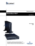
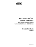
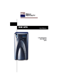
Figure 1
Front view of UPS
Fault
Indicator
OFF Button
Load Level
Indicators
ON/Alarm Silence/
Battery Test Button
Battery Level
Indicators
Voltage
Programming
Button
UPS Status
Indicators
UPS Display
(bezel removed)
7
Introduction
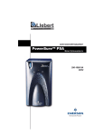
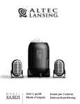
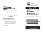
Figure 2
REPO
1000 and 1440VA models—rear view
Intellislot Port
Output
Data Line
Connectors Receptacles
Circuit Breaker
INPUT
BREAKER
PUSH TO RESET
OUT
REPO
IN
LOAD 1
BATTERY
CONNECTOR
1440VA/DC 48V/30A
1000VA/DC 48V/20A
PHONE / FAX / MODEM / NETWORK
PROTECTION
RS-232
1
2
3
4
+
INPUT
LOAD 2
-
INTELLISLOT
External Battery
Cabinet Connector
AC Input
USB Port
RS232 (DB-9)
Port
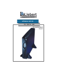
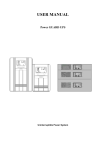
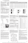
Figure 3
REPO
2200 and 3000VA models—rear view
Intellislot
Port
Input Circuit
Breaker
Data Line
Connectors
PHONE / FAX /
MODEM / NETWORK
PROTECTION
1
2
3
4
IN
REPO
OUT
Output Circuit
Breaker 1
LOAD 1
BREAKER
Output
Receptacles
BATTERY
CONNECTOR
2200V/A/DC 72V30A
3000V/A/DC 72V40A
10A/260VAC
LOAD 2
BREAKER
INTELLISLOT
INPUT
+
RS-232
INPUT
BREAKER
PUSH TO
RESET
USB
Port
AC Input
LOAD 3
Output
Receptacle
RS232 (DB-9)
Port
8
Output Circuit
Breaker 2
External Battery
Cabinet Connector
Major Components
3.0
MAJOR COMPONENTS
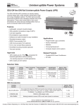
Figure 4
Line diagram of S3K2U 1000VA & 1440VA
Input
EMI/RFI
Filter
Relay
AVR
Transformer
Charger
Battery
Inverter
Output
G
G
Figure 5
Input
Line diagram of S3K2U 2200VA & 3000VA
EMI/RFI
Filter
Relay
AVR
Transformer
Charger
Battery
DC-to-DC
Converter
Output
Bi-Directional
Converter
G
3.1
G
Transient Voltage Surge Suppression (TVSS) and EMI/RFI Filters
These UPS components provide surge protection and filter both electromagnetic interference (EMI)
and radio frequency interference (RFI). They minimize surges or interference present in the mains
line and keep the sensitive equipment protected.
3.2
Relay
In Normal mode the Relay passes mains AC power to the connected load. When input mains voltage
or frequency is outside acceptable limits, the Relay activates and transfers the UPS to battery.
9
Major Components
3.3
Automatic Voltage Regulator
The Automatic Voltage Regulator (AVR) protects connected equipment from power spikes, sags and
other abnormalities by raising (boosting) or lowering (bucking) the output voltage as needed. This
keeps the UPS output voltage within the connected equipment’s tolerance and accommodates wide
mains voltage fluctuations without utilizing the batteries.
3.4
Battery Charger
In Normal mode, the Battery Charger converts mains AC power into regulated DC power to float
charge the battery. It is continuously charging the battery whenever the UPS is plugged into a power
outlet and mains power is within acceptable limits - even if the UPS is turned Off.
3.5
Battery
The S3K2U utilizes valve-regulated, nonspillable, lead acid batteries. To maintain battery design life,
operate the UPS in an ambient temperature of 20°C to 25°C (68°F to 77°F). Optional external battery
cabinets are available to extend battery run times.
3.6
Inverter—1000/1440 Models Only
In battery mode operation, the inverter utilizes the DC output of the battery and inverts it into precise, regulated, sinewave AC power.
3.7
DC-to-DC Converter—2200/3000 Models Only
The DC-to-DC Converter utilizes energy from the battery system and raises the DC voltage to the
optimum operating voltage for the Bi-Directional Converter. This allows the Bi-Directional Converter
to operate continuously at its optimum efficiency and voltage, thus increasing reliability.
3.8
Bi-Directional Converter—2200/3000 Models Only
In normal operation, the Bi-Directional Converter changes mains AC power into regulated DC power
to “float charge” the battery system. This converter is continuously charging the battery whenever the
UPS is plugged into a power outlet and mains power is within acceptable limits—even if the UPS is
turned Off. When mains power fails, the Bi-Directional Converter draws energy from the battery
through the DC-to-DC Converter and inverts it into a regulated sinewave supplying power to connected equipment.
10
What’s Included
4.0
WHAT’S INCLUDED
The S3K2U unit is shipped with the following items:
•
•
•
•
•
•
•
•
•
•
•
•
•
•
S3K2U user manual
Warranty Card
MultiLink serial cable (black), 3m (10 ft)
Contact Closure Cable (gray), 3m (10 ft)
USB cable, 1.8m (6 ft)
RJ-11 cord, 2.1m (7 ft)
Rack mount handles
Support base
Fixed rails
Mounting hardware (screws/washers)
Front bezel
Vertical display overlay
10A output power cords, 2.0m (6.6 ft.)
Input power cord, 2200 and 3000 VA models only
Vertical
display
overlay
Support base
Contact
Closure
Cable
3m (10 ft)
Gray
Fixed rails
MultiLink
serial cable
3m (10 ft)
Black
USB cable
1.8m (6 ft)
RJ-11 cord
2.1m (7 ft)
Mounting hardware
(screws & washers)
10A output
power cords,
2.0m (6.6 ft.)
Input power cords,
2200 & 3000 VA models only
11
Front bezel
Rack
mount
Installation
5.0
INSTALLATION
5.1
Preparation
1. Visually inspect the UPS for freight damage. Report damage to the carrier and your local
distributor, Sola/Hevi-Duty representative or Sola/Hevi-Duty Technical Services.
!
CAUTION
The UPS is heavy (see Table 5 - Battery cabinet specifications). Take proper precautions
when lifting or moving it.
2. Decide where to place the S3K2U. Install the UPS indoors in a controlled environment where it
cannot be accidentally turned Off. Place it in an area of unrestricted airflow around the unit,
away from water, flammable liquids, gases, corrosives, and conductive contaminants. Maintain a
minimum clearance of 100mm (4 inches) in the front and rear of the UPS. Maintain an ambient
temperature range of 0°C to 40°C (32°F to 104°F).
NOTE
UPS operation in temperatures above 25°C (77°F) reduces battery life.
3. The S3K2U may be installed in either a tower configuration or in a rack, depending on available
space and use considerations. Determine the type of installation and follow the appropriate
instructions in either Tower UPS Installation or Rack-Mount UPS Conversion and
Installation.
5.2
Tower UPS Installation
When using the S3K2U in a tower configuration, use the included support base (shown below, left) to
stabilize the UPS. If two or more battery cabinets are added, the spacers—included with the battery
cabinets—should be used to accommodate the additional cabinets.
Figure 6
Support base for tower configuration
Tower Stand - Fully Extended
Spacers Can be Added to Accommodate External Battery Cabinets
Connectors Snap into Slots on Base
1. To orient the display for vertical viewing, remove the front plastic bezel by pulling forward evenly
on both sides.
2. Peel the backing from the vertical display overlay and apply to the existing display.
3. Snap the front bezel back into place.
5.3
Rack-Mount UPS Conversion and Installation
NOTE
When rack mounted, the UPS must be supported by a shelf, slide rails, brackets or fixed rails
on each side. The rack mount handles WILL NOT support the weight of the UPS. They are
used to move the UPS into and out of the rack.
1. For fixed rail installations, install the rack mount handles using four (4) M4x6 screws (see
Figure 7).
12
Installation
Figure 7
Rack mount handles
Two (2) M4x6
Flat Head Screws
Two (2) M4x6
Flat Head Screws
Rack Mount Handles
M4x6 Flat Screw
2. Unpack the two fixed rail assemblies and mounting hardware. Loosen the wing nuts and extend
the inner members to their outermost position (see Figure 8).
Figure 8
Fixed rails with inner members extended
Wing Nuts for
Adjustment
Adjustable Slide
Assembly
Adjustable Length
Maximum 800 mm
Minimum 485 mm
!
CAUTION
Reduce the risk of tipping the rack enclosure by placing the UPS or battery cabinet in the
lowest possible rack position.
3. Determine the height position inside the rack enclosure where you want to mount the UPS or
battery cabinet. Make sure fixed rails are at the same mounting height on each of the four (4) rack
mounting rails.
4. Attach the two (2) fixed rails to the racks mounting rails. The fixed rail assemblies fit on the
inside of the rack mounting rails.
5. Insert two (2) M5 flat head screws loosely (finger-tight) into the top and bottom holes on the front
of the fixed rail assembly (see Figure 9).
6. Extend fixed rail by sliding inner member backward until it touches the rear rack mounting rail.
7. Insert two (2) M5 screws loosely (finger-tight) into top and bottom holes on the rear of the fixed
rail assembly.
8. Check alignment of fixed rails and tighten all screws to ensure locking action.
13
Installation
Figure 9
Rack mounting rails and slide assemblies
B
B
A
A
A
A - Washer
B - M5x12 Flat Screw
A
B
B
9. Lay the UPS in rack-mounting position on the fixed rails. The UPS should move smoothly forward
and backward on the fixed rails. If not, recheck alignment.
!
CAUTION
Lifting equipment into rack may be a two-person job, depending on weight of equipment.
10. Use the extra M5 screws provided, secure front of the UPS to rack mounting rails to prevent the
UPS from sliding out of position.
11. S3K2U 230 VAC models are not supplied with an input power lead for connection to the mains
supply. Additional input/output cords may be obtained from your dealer. The input power cord
must have a minimal cross-sectional area of 1mm2.
12. Shut down the load equipment and turn off the mains
Vertical
supply. Unplug the load equipment's power input
overlay
for tower
cable from the mains supply socket and plug it into the
UPS
UPS input socket.
Plug the power input cable into the mains supply
socket. Connect the supplied IEC-320-C14 output
power cable between the load equipment input socket
and one of the UPS AC output sockets.
13. Connect all load equipment to the UPS in this
manner.
Horizontal
14. Turn On the UPS by pressing the ON button. Check
overlay for
that the AC Input Indicator is not flashing. If it is
rack UPS
flashing, refer to 11.0 - Troubleshooting. Then turn
On the connected equipment. The UPS is now providing conditioned power to your equipment.
!
CAUTION
!
VORSICHT
To maintain safety (SELV) barriers and electromagnetic compatibility, signal cables should
be segregated and run separately from power cables.
Zur Aufrechterhaltung der Sicherheitsschranken (SELV) und elektromagnetischen
Verträglichkeit sollen Signalkabel getrennt werden und separat von Netzkabeln geführt
werden.
14
Installation
15. Connect Phone/Fax/DSL/Network/Modem devices to data line connectors.
RJ11/RJ45
connection
INPUT
BREAKER
PUSH TO RESET
OUT
REPO
IN
LOAD 1
BATTERY
CONNECTOR
1440VA/DC 48V/30A
1000VA/DC 48V/20A
PHONE / FAX / MODEM / NETWORK
PROTECTION
RS-232
1
2
3
4
+
INPUT
LOAD 2
-
INTELLISLOT
16. Communication options (see 8.0 - Communications for details):
Option 1 - Serial Communications
Serial communications provides parametric data, for example, input voltage and battery voltage.
a. Connect MultiLink serial cable included with the UPS to communications port.
b. Install the MultiLink software. The software and installation instructions, as well as the user
manual, may be downloaded from www.solaheviduty.com/products/software.
Option 2 - Contact Closure Communications
Contact Closure communications provides on-battery and low-battery signals for orderly shutdown.
a. Refer to the MultiLink user manual for instructions on making your own contact closure
cable.
b. Install the MultiLink software. The software and installation instructions, as well as the user
manual, may be downloaded from www.solaheviduty.com/products/software.
Option 3 - USB Communications
a. Connect USB cable provided with the UPS to its USB port and the USB port on your
computer. The S3K2U will work automatically with your built-in power management
software on Windows XP and 2000 and Mac OS 10.2 or later (see 8.3 - USB Interface Port
for details).
Option 4 – Intellislot
The UPS contains one communication slot, called “Intellislot™,” to allow the operator to field
install optional communication cards. These optional cards allow the UPS to communicate via
either SNMP Web Card (SNMPWEBCARD), connected directly to the LAN; or Intellislot Relay
Interface card (RELAYCARD-INT) communication card. Once the SNMPWEBCARD is installed,
the Serial communication via the RS232 is disabled. The USB, Intellislot, and Contact Closure
communications operate in parallel.
17. REPO Switch—The S3K2U is equipped with a Remote Emergency Power Off (REPO) switch.
The user must supply a means of interfacing with the REPO circuit to allow disconnecting the
UPS input feeder breaker to remove all sources of power to the UPS and connected equipment to
comply with national and local wiring codes and regulations.
15
Installation
Figure 10 REPO switch connections
REPO Connector
REPO Switch
as shipped
1
2
3
4
REPO connections
for normally open
switch system
1
2
3
Key to REPO switch connections
1. 24 VDC
2. Sense
3. Sense
16
4
REPO connections
for normally closed
switch system (fail-safe)
1
2
3
4
Installation
External Battery Cabinet Installation
Optional Sola/Hevi-Duty external battery cabinets may be connected to the UPS to provide additional
battery run time. External battery cabinets are designed to be placed all on one side of the UPS or
stacked beneath the UPS. The run time is limited to a maximum of four (4) hours.
!
CAUTION
The external battery cabinet(s) are heavy (see 12.0 - Specifications (Sechnische Daten)).
External battery cabinets can be used in rack-mount or tower configuration. Take proper
precautions when lifting them.
!
VORSICHT
Externe Batteriegehäuse sind schwer (siehe 12.0 - Technische Daten). Externe
Batteriegehäuse können in einer Gestellmontage- oder Turmkonfiguration eingesetzt werden.
Ergreifen Sie die entsprechenden Vorsichtsmaßnahmen, wenn sie gehoben werden müssen.
1. Visually inspect the external battery cabinet for freight damage. Report damage to the carrier
and your local distributor, Sola/Hevi-Duty Representative or Sola/Hevi-Duty Technical Services.
2. The rack-mount handles are shipped with the external battery cabinet and may be installed at
this time (see 5.3 - Rack-Mount UPS Conversion and Installation).
3. Fixed rails and securing hardware ship with the external battery cabinet. Fasten the fixed rails
into position with the screws per the instructions included with the UPS. Repeat
Steps 1 through 10 from 5.3 - Rack-Mount UPS Conversion and Installation.
4. Use the support bases included with the UPS for the tower option to prevent tip-over. One
additional set of support base spacers ships with each external battery cabinet.
5. Connect the supplied external battery cabinet cable to the rear of the external battery cabinet,
then to the rear of the UPS, as shown at right.
6. The UPS is now equipped with additional backup battery run time. For approximate battery run
times, refer to Table 6 - Battery run times.
BATTERY
CONNECTOR
BATTERY
CONNECTOR
INPUT
BREAKER
PUSH TO RESET
IN
OUT
REPO
1
2
3
4
LOAD 1
PHONE / FAX / MODEM / NETWORK
PROTECTION
BATTERY
CONNECTOR
1440VA/DC 48V/30A
1000VA/DC 48V/20A
+
RS-232
5.4
INPUT
LOAD 2
INTELLISLOT
17
-
Controls and Indicators
6.0
CONTROLS AND INDICATORS
All indicators illuminated
for illustrative purposes only.
6.1
ON/Alarm Silence/Battery Test Button
This button controls output power to connected load(s) and has three functions:
•On
•Alarm Silence
•Battery Test
ON—When the UPS is Off, pressing the ON/Alarm Silence/Battery Test button for more than one
(1) second will start the UPS, and an audible alarm sounds briefly. The UPS is capable of starting on
battery (battery start).
Alarm Silence—When a UPS audible alarm is active, pressing and releasing the ON/Alarm Silence/
Battery Test button will silence the active audible alarm, whether mains power is present or not.
Once the alarm silence function has been activated, all active audible alarms will remain silenced
until a new alarm condition is detected.
NOTE
The LOW BATTERY, OVER TEMP and OVERLOAD warning
audible alarms CANNOT be silenced.
Battery Test—To initiate a manual battery test, press the ON/Alarm Silence/Battery Test button for
at least one second while operating from mains power with no alarm conditions present.
• If all five (5) Battery indicators are not illuminated, allow the UPS to recharge the batteries for
24 hours.
• After 24 hours, retest the batteries.
• After the batteries have been retested, if all five (5) Battery indicators are not illuminated, contact your local distributor, Sola/Hevi-Duty representative or Sola/Hevi-Duty Technical Services.
6.2
OFF Button
When the UPS is on (in either Normal or Battery mode), pressing the OFF button
for more than one (1) second will shut down the UPS. An audible alarm sounds
briefly.
18
Controls and Indicators
6.3
Voltage Programming Button
The S3K2U contains a Voltage Programming button that allows the operator to select the
nominal mains voltage. This setting changes the mains transfer points (low and high) of the
UPS and the nominal output voltage when operating in Battery mode. The operator can
select between 220, 230 and 240VAC output. The factory-default setting is 230VAC.
The Voltage Programming button is a push button type and is behind the plastic bezel on
the front panel of the UPS. To access the button, the front bezel must be removed.
6.4
Load Level Indicators—4 green, 1 amber
The Load Level Indicators display the approximate electrical load placed upon the UPS.
The UPS Load Level Indicators are displayed in 25% increments as shown in Figure 11.
Figure 11 Load level indicators—4 green, 1 amber
Upon detection of an output overload condition, the amber overload (>100%) indicator flashes and an
audible alarm activates. If the UPS shuts down due to an overload condition, the amber overload
(>100%) indicator illuminates (see 11.0 - Troubleshooting for details).
6.5
Battery Level Indicators—5 green
The Battery Level Indicators display the approximate battery capacity.
The approximate battery capacity is displayed when the UPS is operating in Normal, Buck/Boost, or
Battery mode.
The Battery Level Indicators are displayed in 20% increments as shown in Figure 12:
Figure 12 Battery level indicators—5 green
The S3K2U is equipped with automatic and remote battery test features. The automatic test occurs
every 14 days if mains has not been interrupted; this option may be configured by the user. Should
the battery fail this test, the amber Battery Indicator will be illuminated and an alarm will sound (see
11.0 - Troubleshooting for details).
The remote test feature functions with MultiLink 3.x software and can remotely initiate the battery
test.
6.6
AC Input Indicator—Green
The AC Input Indicator illuminates when mains power is available and within the input specifications.
6.7
Buck/Boost Indicator—Green
The Buck/Boost Indicator illuminates when the UPS is operating in Boost mode to compensate for a
low mains voltage condition. This indicator flashes when the UPS is operating in Buck mode to compensate for a high mains voltage condition (see 11.0 - Troubleshooting for details).
6.8
Battery Indicator—Green/Amber
The Battery Indicator illuminates green when the UPS is operating on battery and flashes green
when a low battery condition occurs. The Battery Indicator illuminates amber when a bad battery is
detected, indicating that the batteries need to be replaced (see 11.0 - Troubleshooting for details).
19
Controls and Indicators
6.9
Over Temp Indicator—Amber
The Over Temp Indicator flashes when the UPS detects an over temperature condition. This indicator
illuminates when the UPS shuts down due to an over temperature condition (see 11.0 - Troubleshooting for details).
6.10
Fault Indicator—Red
The Fault Indicator illuminates when the UPS detects an internal problem (see 11.0 - Troubleshooting for details).
20
Modes of Operation
7.0
MODES OF OPERATION
7.1
Normal Mode
During Normal mode operation, the S3K2U supplies conditioned, computer-grade power to the connected equipment: mains power passes through the TVSS circuitry and the EMI/RFI filters and then
through the Inverter (1000VA & 1440VA) / Bi-Directional Converter (2200VA & 3000VA) to connected equipment.
When the UPS is in Normal mode, the AC Input Indicator illuminates green. The UPS display in
Figure 13 shows the UPS operating in Normal mode with 26% - 50% load connected to the output.
Figure 13 Normal mode operation with 26-50% load
Mains power present ...
... and within operational limits
The S3K2U continuously monitors the batteries to maintain them in a fully charged state. The battery charger operates whenever AC power is present, even if the UPS is switched Off. By default, the
UPS is set to perform an automatic battery test after it has been operating continuously for two (2)
weeks. The automatic battery test can be disabled via MultiLink.
7.2
Buck/Boost Mode
The Automatic Voltage Regulator (AVR) circuitry compensates for fluctuations in mains power, such
as voltage surges and sags. When the S3K2U detects an abnormality, it raises the undervoltage
(boost) or lowers the overvoltage (buck) as needed. The AVR operates automatically and maintains
the output voltage to the connected critical equipment, without utilizing the batteries.
The Buck/Boost Indicator flashes green when the UPS is operating in Buck mode and illuminates
green when the UPS is operating in Boost mode (see 11.0 - Troubleshooting for details).
Figure 14 Buck/Boost mode operation with 51-75% load and 21-40% battery capacity
Indicator shows
UPS in Boost Mode
(solid green)
7.3
Battery Mode
The UPS switches to Battery mode in the event of an extreme input voltage/frequency condition or
complete mains failure. The battery system supplies power through the Inverter (1000VA & 1440VA)
or through the DC-to-DC converter to the Bi-Directional Converter (2200VA & 3000VA) to generate
power for the connected equipment.
21
Modes of Operation
When the UPS is in Battery mode, the Battery Indicator illuminates green and an alarm sounds
every 10 seconds. As capacity decreases, fewer indicators remain illuminated. Figure 15 shows the
UPS in Battery mode with 61% - 80% battery capacity remaining.
Figure 15 Battery mode at 61 – 80% battery capacity
Battery Indicator
illuminated
When a low battery condition occurs, the Battery Indicator flashes green and the alarm sounds every
half-second. The default low battery warning is two (2) minutes but can be configured via MultiLink.
For more information, refer to 11.0 - Troubleshooting.
Figure 16 Low Battery mode
Battery Indicator
flashes green
For approximate battery run times, refer to Table 6 - Battery run times. These run times are
approximates based on resistive load and an ambient temperature of 25°C (77°F). To increase this
time, turn Off non-essential pieces of equipment, such as idle computers and monitors, or add external battery cabinets.
!
CAUTION
Turning Off the UPS while it is in battery mode will result in loss of output power.
7.4
Battery Recharge Operation
Once mains power is restored, the UPS resumes normal operation. At this time, the Battery Charger
begins recharging.
22
Communications
8.0
COMMUNICATIONS
8.1
DB-9 Connector
The UPS has a DB-9 (9 pin female) connector on the rear to allow UPS status communications with a
computer system running MultiLink software. The DB-9 is capable of supplying serial communication, on battery and low battery signals. MultiLink, Sola/Hevi-Duty’s UPS monitoring and shutdown
software, is shipped with the UPS, along with a 3m (10 ft) DB-9 cable required for running MultiLink.
When MultiLink is installed on the host computer, the UPS can signal “on battery” and “low battery”
using opto-couplers. When the UPS is operating in Battery mode, it can receive a signal from the host
computer system that will shut down the UPS (after gracefully shutting down the operating system
on the host computer system) when the remaining battery run time is low. The timing of the signal
depends on MultiLink’s configuration settings. This shutdown signal (5-12VDC) must have a duration of at least 2 seconds for the UPS to be shut down. The UPS communicates via serial communications using Liebert ESP II protocol.
Table 1
DB-9 pin assignment
DB-9 Pin
Assignment Description
1
Low Battery (open collector)
2
UPS TxD
3
UPS RxD
4
Battery Mode Shutdown (5-12V)
5
Common
6
Any Mode Shutdown (short to pin 5)
7
Low Battery (open emitter)
8
Mains Fail (open emitter)
9
Mains Fail (open collector)
Pin Assignment
6
7
8
Collector to Emitter*
9
330 Ohms
1
8.2
2
3
4
Open
(+) Collector
(-)
5
Open
Emitter
Remote Shutdown Via the DB-9 Connector
The S3K2U can be shut down remotely by shorting Pins 5 and 6 or via Pins 4 and 5 of the DB-9 connector.
8.2.1
Any Mode Shutdown—Via Pins 5 & 6
When Pin 6 is shorted to Pin 5, the UPS output is shut Off regardless of what mode the UPS is operating in. The UPS cannot be started as long as the pins are shorted. When the short is removed, the
UPS output can be enabled by pressing the ON/Alarm Silence/Battery Test button.
8.2.2
Battery Mode Shutdown—Via Pins 4 & 5
While the UPS is operating on battery (with no battery test in progress), a 5-12VDC signal for 2 seconds or longer is required to signal a shutdown. Signals for less than 2 seconds are ignored.
After Pin 4 receives the shutdown signal, a 2-minute shutdown timer inside the UPS begins a countdown. The timer cannot be stopped. If mains power returns during the 2-minute timer countdown, the
shutdown timer continues until the end of 2 minutes and then the UPS turns Off. By default, autorestart is enabled so the UPS will restart after 10 seconds. If autorestart is disabled via MultiLink software, the UPS remains Off until a manual restart.
23
Communications
8.3
USB Interface Port
The S3K2U has a USB interface port for communication that will work with the built-in Microsoft
Power Manger software on the user’s PC, if so equipped. It will provide UPS status and manages the
automatic orderly shutdown of the computer. The UPS’s USB communications meet HID standard,
version 1.11. All USB models are compatible with Microsoft Windows 2000, Windows XP and Mac OS
10.2 or later. All USB models ship with a 1.8m (6 ft) USB cable.
8.4
Data Line Protection Connectors
Data line (in and out) connectors are on the rear of the UPS and provide transient voltage surge suppression (TVSS) for Phone/Fax/DSL/Internet/Modem devices.
8.5
UPS Intelligent Communications
The S3K2U is equipped with an Intellislot® port to provide advanced communication and monitoring
options.
MultiLink software continually monitors the UPS and can shut down your computer or server in the
event of an extended power failure.
MultiLink can also be configured for use without the serial cable when the Intellislot SNMPWEBCARD is installed in the UPS. Additionally, MultiLink can be configured to coordinate shutdown
across the network with other computers running MultiLink when you purchase a MultiLink License
Kit. For more information about the Intellislot SNMPWEBCARD and MultiLink License Kits, visit
our Web site (www.solaheviduty.com) or contact your local distributor, Sola/Hevi-Duty represenative
or Sola/Hevi-Duty Technical Services.
Several option cards are available for use in the Intellislot port of the S3K2U. The Intellislot SNMPWEBCARD provides SNMP and Web-based monitoring and control of the UPS across the network.
The Intellislot MultiPort 4 Card allows you to install MultiLink software on four computers and coordinate shutdown in the event of a power failure.
The RELAYCARD-INT provides dry contact relay outputs for custom-wired applications and delivers
support for built-in shutdown for AS/400 systems.
NOTE
The USB, Intellislot and Contact Closure communications operate in parallel. Using the
SNMPWEBCARD disables the Serial Communications of the DB-9.
!
CAUTION
To maintain safety (SELV) barriers and for electromagnetic compatibility, signal cables
should be segregated and run separate from all other power cables, where applicable.
24
Voltage Programming Procedure
9.0
VOLTAGE PROGRAMMING PROCEDURE
Figure 17 Load Level Indicators
Load Level
Indicators
Voltage
Programming
Button
1. Remove the front bezel from the UPS.
2. UPS must be operating in Normal (AC) mode.
NOTE
Mains power will be applied to the connected load.
3. The AC Input, Load, and Battery Level Indicators should be lit.
4. Press the Voltage Programming button for at least 5 seconds to enter the Configuration mode.
The UPS will beep and all of the indicators on the front panel display will flash on and off for
approximately 5 seconds. The next cycle will display the current configuration, either 220, 230 or
240 VAC. One of the Load Level Indicators will be flashing. Initially, the 0%-25% Load Level
Indicator will be flashing, indicating the default setting of 230V as shown in Figure 17.
5. Press the ON button to step through the voltage settings until the appropriate Load Level
Indicator is flashing.
6. Press the Voltage Programming button. The UPS will return to Normal mode operation.
The Voltage Programming button allows the operator to select the mains transfer voltage at which
the UPS will switch to battery power (see Table 2). This also changes the inverter voltages.
Table 2
Voltage settings
Input Voltage
Range
Output Voltage
(Battery Mode)
120V (230V)
166 - 272VAC
(default)
230VAC
110V (220V)
158 - 260VAC
220VAC
127V (240V)
172 - 283VAC
240VAC
Setting
25
Maintenance
10.0 MAINTENANCE
The S3K2U UPS requires very little maintenance. Follow these practices to prevent problems.
10.1
Cleaning the UPS
The following will help ensure trouble-free operation for years:
• Vacuum dust from the ventilation intake occasionally.
• Wipe the cover periodically with a dry cloth.
10.2
Maintaining Batteries
The batteries are valve-regulated, nonspillable, lead acid and must be kept charged to retain their
design life. The UPS continuously charges the batteries when connected to the mains supply, even
while the UPS is switched Off.
When storing the UPS, it is recommended to plug in the UPS for at least 24 hours every four to six
months to ensure full recharge of the batteries.
The S3K2U is designed to allow the user to replace the internal batteries safely. Read the safety cautions before proceeding. Contact your local distributor, Sola/Hevi-Duty representative or Sola/HeviDuty Technical Services to obtain the appropriate replacement battery kit part number and pricing.
10.3
Battery Replacement
!
CAUTION
A battery can present a risk of electrical shock and high short circuit current. The following
precautions should be observed before replacing the batteries:
•
•
•
•
•
•
•
•
Remove rings, watches, and other metal objects.
Use a Phillips (crosshead) screwdriver with insulated grips.
Do not lay tools or other metal objects on top of the batteries.
If the battery replacement kit is damaged in any way or shows signs of leakage, contact
your local distributor, Sola/Hevi-Duty representative or Sola/Hevi-Duty Technical Services
immediately.
Do not dispose of batteries in a fire. The batteries may explode.
Dispose of old batteries according to local codes.
Risk of explosion if battery is replaced by an incorrect type. Refer to 12.0 - Specifications
(Sechnische Daten) for battery information.
Do not open or mutilate the batteries. Released electrolyte is harmful to skin and eyes. It is
toxic.
26
Maintenance
!
VORSICHT
Bei einer Batterie ist das Risiko eines Stromschlags und eines starken Kurzschlussstroms
gegeben. Folgende Vorsichtsmaßnahmen sollten beim Austausch der Batterien beachtet
werden:
•
•
•
•
•
•
•
•
Armbanduhren, Ringe und sonstige Metallobjekte sind zu entfernen.
Verwenden Sie einen Kreuzschlitzschraubendreher mit isoliertem Griff.
Legen Sie keine Werkzeuge oder sonstige Metallgegenstände oben auf die Batterien.
Wenn der als Ersatz gedachte Batteriesatz in irgendeiner Weise beschädigt ist oder
Leckagen aufweist, wenden Sie sich umgehend an Ihren örtlichen Händler oder Sola/HeviDuty-Vertreter.
Batterien dürfen auf keinen Fall verbrannt werden. Die Batterien könnten dabei
explodieren.
Alte Batterien müssen entsprechend der örtlichen Vorschriften entsorgt werden.
Explosionsgefahr, wenn die Batterie durch einen falschen Batterietyp ersetzt wird.
Informationen zu Batterien finden Sie unter 12.0 – Technische Daten.
Die Batterien dürfen nicht geöffnet oder zerstört werden. Die austretende Füllsäure ist
schädlich für Haut und Augen. Sie ist giftig.
NOTE
This UPS is equipped with internal “hot swappable” batteries that the user can replace without
shutting down the UPS or connected loads. Caution should be exercised when replacing the
batteries because the load is unprotected from disturbances and power outages during this
procedure.
HINWEIS
Die USV ist mit internen ("hot swappable") Batterien ausgestattet, die der Benutzer ersetzen
kann, ohne die USV oder die angeschlossenen Geräte auszuschalten. Beim Austauschen der
Batterien umsichtig vorgehen, da die angeschlossenen Geräte während dieses Verfahrens nicht
vor Störungen und Stromausfällen geschützt sind.
27
Maintenance
10.3.1 Internal Battery Replacement Procedure
(Verfahren zum Austausch von internen Batterien)
1. Gently remove the front plastic bezel cover from the UPS.
(Demontieren Sie die vordere Kunststoffblendenabdeckung vorsichtig von der USV.)
2. Loosen and remove the five (5) screws on the front cover plate. Lay the cover plate aside for
reassembly.
(Lösen und entfernen Sie die fünf (5) Schrauben an der vorderen Abdeckungsplatte. Legen Sie die
Abdeckungsplatte zum späteren Einbau beiseite.)
3. Loosen and remove four (4) screws on battery bracket.
(Lösen und entfernen Sie die vier (4) Schrauben auf der Batteriehalterung.)
4. Disconnect the two (2) slotted, red and black battery connectors.
(Trennen Sie die zwei (2) geschlitzten roten und schwarzen Batteriestecker ab.)
5. Grasp the battery pack assembly by the pull tab and pull it out of the front of the UPS.
(Packen Sie die Batteriepackbaugruppe an der Zuglasche und ziehen Sie sie vorne aus der USV
heraus.)
6. Unpack the new battery assembly, taking care not to destroy the packing. Compare new and old
battery assemblies to make sure they are the same. If so, proceed with Step 7; otherwise STOP
and contact your local distributor, Sola/Hevi-Duty representative, or Sola/Hevi-Duty Technical
Services.
(Packen Sie die neue Batteriebaugruppe aus; achten Sie dabei darauf, dass die Verpackung nicht
zerstört wird. Vergleichen Sie die neue und alte Batteriebaugruppe um sicherzustellen, dass sie
gleich sind. Wenn dies der Fall ist, fahren Sie mit Schritt 7 fort; anderenfalls FAHREN SIE
NICHT FORT und wenden Sie sich an Ihren örtlichen Händler oder Sola/Hevi-Duty-Vertreter
oder den weltweiten Kundendienst von Sola/Hevi-Duty.)
7. Slide in the new replacement battery pack.
(Schieben Sie das neue Ersatzbatteriepack hinein.)
8. Reattach the battery bracket with the four (4) screws.
(Befestigen Sie die Batteriehalterung wieder mit den vier (4) Schrauben.)
9. Reconnect the two (2) slotted red and black battery connectors.
(Schließen Sie die zwei (2) geschlitzten roten und schwarzen Batteriestecker wieder an.)
10. Reattach the front battery door with the five (5) screws.
(Bauen Sie die vordere Batterieabdeckung mit den fünf (5) Schrauben wieder ein.)
11. Reattach the front plastic bezel cover to the UPS.
(Bauen Sie die vordere Kunststoffblendenabdeckung wieder an die USV an.)
Figure 18 Battery replacement procedure (Batterieaustauschverfahren)
00 0102 03
Battery Bracket
Batteriehalterung
Cover Plate
Abdeckungsplatte
Front Plastic Bezel
Vordere Kunststoffblende
28
Battery
Connectors
Batteriestecker
Battery Pull Tab
Batteriezuglasche
Troubleshooting
11.0 TROUBLESHOOTING
The information below indicates various symptoms a user may encounter in the event the S3K2U
experiences a problem. Use this information to determine whether external factors caused the problem. See Table 3 - Troubleshooting chart for suggested remedy.
1. An alarm sounds, alerting that the UPS requires attention. The alarm can be silenced except for
low battery, overload warning and over-temperature warning conditions.
2. One or more additional indicators will be illuminated to provide a diagnostic aid to the operator,
as described below:
Figure 19 Status indicators
All indicators illuminated
for illustrative purposes only.
29
Troubleshooting
If the UPS fails to operate properly, turn Off the unit and repeat the steps in 5.0 - Installation. If the
problem persists, refer to Table 3:
Table 3
Troubleshooting chart
Problem
UPS will not start
UPS starts on battery, but will not
switch to AC
Cause
Solution
Short circuit
Check the circuit protector on the rear of the UPS.
If it is tripped, reset it and restart the UPS. For
further help, contact your local distributor, Sola/
Hevi-Duty representative, or Sola/Hevi-Duty
Technical Services.
Battery disconnected or is
completely discharged
Check for proper connection of battery or
batteries.
UPS not plugged in
Plug in the power cord securely.
Circuit protector tripped
Reset the circuit protector and restart the UPS.
Input voltage below threshold
Wait until the voltage rises to an appropriate level
or have the mains power checked by a qualified
electrician.
AC overvoltage
Wait until voltage lowers to an appropriate level
or have the mains power checked by a qualified
electrician.
Load exceeded UPS capacity
(110%), All Load Level Indicators
are illuminated; continuous beep
Check load level display and remove nonessential loads. Recalculate the load and reduce
number of loads connected to UPS - the total
wattage of your equipment must not exceed the
capacity of the UPS.
Over temperature shutdown, Over
Temp Indicator lit; continuous
beep
Make sure that the UPS is operating in 0°C to
40°C (32°F to 104°F) and that it has adequate
ventilation.
MultiLink shutdown
Consult the MultiLink user manual or contact your
LAN administrator.
Internal UPS fault, Fault Indicator
Lit; continuous beep
Contact your local distributor, Sola/Hevi-Duty
representative, or Sola/Hevi-Duty Technical
Services.
UPS shutdown due to a command
from the communications port(s),
Load Level 0-25% Indicator
illuminated
Your UPS has received a signal or command
from the attached computer. If this was
inadvertent, ensure the communication cable
used is correct for your system. For assistance,
contact your local distributor, Sola/Hevi-Duty
representative, or Sola/Hevi-Duty Technical
Services.
All Battery Level Indicators
flashing
UPS is unable to perform manual
or remote battery test; beep every
half second for five seconds
Check battery connections,
completely power down and restart UPS.
NOTE: If the battery circuit opens while the UPS
is running, it will be detected when the next
battery test is performed.
Battery Indicator illuminated
amber; long beep every minute
UPS failed battery test
Initiate battery test again.
Batteries weak
Recharge batteries.
Batteries need to be replaced
Replace batteries.
Over Temp Indicator flashing
Over temperature warning; beep
every half second
Make sure that the UPS is operating in 0°C to
40°C (32°F to 104°F) and that it has adequate
ventilation.
Fault Indicator lit but UPS is On
Fault warning; beep every half
second
Reset UPS.
UPS shuts down
30
Specifications (Sechnische Daten)
12.0 SPECIFICATIONS (SECHNISCHE DATEN)
Table 4
UPS specifications
Model Number
S3K2U1000-5
S3K2U1440-5
S3K2U2200-5
S3K2U3000-5
Power Rating, VA/W
1000VA/750W
1440VA/1080W
2200VA/1650W
3000VA/2250W
87 x 557 x 430
(3.43 x 22 x 17)
87 x 557 x 430
(3.43 x 22 x 17)
87 x 612 x 430
(3.43 x 24.1 x 17)
87 x 612 x 430
(3.43 x 24.1 x 17)
300 x 706 x 598
(11.8 x 27.8 x 23.5)
300 x 706 x 598
(11.8 x 27.8 x 23.5)
333 x 864 x 598
(13.1 x 34 x 23.5)
333 x 864 x 598
(13.1 x 34 x 23.5)
28 (61.7)
31.0 (68.2)
35.0 (77.0)
37.0 (81.6)
36.6 (80.7)
39.0 (85.8)
43.6 (95.9)
45.6 (100.5)
Dimensions, W x D x H, mm (in)
Unit
Shipping
Weight, kg (lbs)
Unit
Shipping
Input AC Parameters
Rated Input Voltage
220/230/240VAC
Surge Protection
660J
Voltage Range Without
Battery Operation
158VAC - 283VAC, configurable
Frequency Range
Input AC Inlet
45 - 65 Hz (±0.1 Hz)
IEC-320-C14
IEC-320-C14
IEC-320-C20
IEC-320-C20
(8) IEC-320-C13
(8) IEC-320-C13
(8) IEC-320-C13
(1) IEC-320-C19
(8) IEC-320-C13
(1) IEC-320-C19
Output AC Parameters
Output Receptacles
Voltage (Normal mode)
220/230/240VAC (configurable) ±10%
Voltage (Battery Mode)
220/230/240VAC (configurable);
±5% before low battery warning; ±8% after low battery warning
Transfer Time
4-6 ms typical
Waveform
Sinewave
Frequency (Normal Mode)
45 - 65 Hz (±0.1 Hz)
Frequency (Battery Mode)
50 or 60 Hz (±0.5 Hz); auto sensing
Overload Warning
>100 - 110%
Overload Shutdown
>200% - short circuit; after 15 cycles (normal mode)
Battery Parameters
Type
QuantityxVoltagexRating
Valve-regulated, nonspillable, lead acid
4 x 12V x 7Ah
4 x 12V x 7Ah
6 x 12V x 7Ah
Battery Manufacturers
CSB, B&B Battery, and EnerSys
Backup Time
See Table 6 - Battery run times
Full Load
11
Half Load
26
Recharge Time
6 x 12V x 9Ah
5
5
6
16
16
16
4 hours to 90% of rated capacity, after full discharge into resistive load
Environmental
Operating Temperature
0°C to + 40°C (+32°F to + 104°F)
Storage Temperature
-15°C to + 40°C (+5°F to + 104°F)
Relative Humidity
Operating Altitude
Audible Noise
0% to 95%, non-condensing
Up to 2,000m (6,500 ft) at 35°C (95°F)
without derating
Up to 3,000m (10,000 ft) at 35°C (95°F)
without derating
<40 dBA, internal fan(s) Off
<50 dBA, internal fan(s) On
<40 dBA, internal fan(s) Off
<60 dBA, internal fan(s) On
31
Specifications (Sechnische Daten)
Table 4
UPS specifications (continued)
Model Number
S3K2U1000-5
S3K2U1440-5
S3K2U2200-5
S3K2U3000-5
Agency
Safety
EN 62040-1-1; TUV/GS listed; CE compliance mark
Surge
EN61000-4-5, Level 3, Criteria B
ESD
EN61000-4-2, Level 3, Criteria B
Susceptibility
EN61000-4-3, Level 3, Criteria A
Electrical Fast Transient
EN61000-4-4, Level 4, Criteria A
Emissions
EN 50091-2, Class B
Conducted Immunity
EN61000-4-6
Harmonics
EN61000-3-2
Flicker
EN61000-3-3
Transportation
Table 5
ISTA Procedure 1A Certification
Battery cabinet specifications
Model Number
Used w/UPS Model
S3K48BAT
S3K72BAT
S3K2U1000-5
S3K2U1440-5
S3K2U2200-5
S3K2U3000-5
87 x 557 x 430 (3.43 x 22 x 17)
87 x 612 x 430 (3.43 x 24.1 x 17)
300 x 706 x 598
(11.8 x 27.8 x 23.5)
333 x 864 x 598
(13.1 x 34 x 23.5)
Dimensions, W x D x H, mm (in)
Unit
Shipping
Weight, kg (lbs)
Unit
Shipping
30 (66.1)
46 (101.4)
38.6 (85.1)
53.6 (118.1)
Battery Parameter
Type
Quantity x Voltage x
Rating
Valve-regulated, nonspillable, lead acid
2 strings of 4 x 12V x 7Ah
2 strings of 6 x 12V x 9Ah
Battery Manufacturers
CSB, B&B Battery and EnerSys
Backup Time
See Table 6 - Battery run times
Environmental
Operating Temperature
0°C to + 40°C (+32°F to + 104°F)
Storage Temperature
-15°C to + 40°C (+5°F to + 104°F)
Relative Humidity
0% to 95%, non-condensing
Operating Altitude
Up to 3,000m (10,000 ft) at 35°C (95°F) without derating
Agency
Safety
EN 62040-1-1; TUV/GS listed; CE compliance mark
Emissions
Transportation
EN 50091-2, Class B
ISTA Procedure 1A Certification
32
Specifications (Sechnische Daten)
Table 6
Internal
Battery
(minutes)
Internal
Battery + 1
External
Battery
Cabinet
(minutes)
Internal
Battery + 2
External
Battery
Cabinet
(minutes)
Battery run times
Load%
1000VA
1440VA
2200VA
3000VA
5%
174
138
171
177
10%
118
79
73
91
20%
65
45
47
47
30%
41
28
26
28
40%
37
24
23
22
50%
26
16
16
16
60%
24
14
13
14
70%
18
10
10
10
80%
16
9
8
9
90%
12
6
6
7
100%
11
5
5
6
5%
513
409
542
542
10%
305
265
266
257
20%
248
188
185
148
30%
177
125
135
141
40%
139
104
122
99
50%
119
72
99
67
60%
98
59
75
53
70%
75
45
55
45
80%
63
40
49
39
90%
53
35
44
34
100%
46
30
40
29
5%
1001
828
—
—
10%
565
461
493
444
20%
409
283
291
249
30%
283
219
222
168
40%
248
177
194
148
50%
209
133
150
129
60%
166
122
137
114
70%
136
98
122
92
80%
127
84
107
71
90%
110
64
92
56
100%
98
56
77
52
33
Specifications (Sechnische Daten)
Table 6
Battery run times
Internal
Battery + 3
External
Battery
Cabinet
(minutes)
Internal
Battery + 4
External
Battery
Cabinet
(minutes)
Load%
1000VA
1440VA
2200VA
3000VA
5%
1174
1001
—
—
10%
1001
655
—
590
20%
565
409
493
300
30%
409
283
283
240
40%
305
257
266
213
50%
274
209
222
168
60%
248
166
185
144
70%
209
136
156
129
80%
188
125
141
116
90%
145
110
131
101
100%
136
95
120
88
5%
—
1174
—
—
10%
1174
828
—
—
20%
828
565
590
444
30%
513
357
395
283
40%
461
292
300
266
50%
305
257
274
222
60%
283
230
240
179
70%
257
188
203
150
80%
239
156
173
139
90%
209
136
156
129
100%
188
125
144
118
NOTE
Approximate discharge times are in minutes and at 25°C (77°F) with resistive load.
Table 7
Technische Daten zur USV
Modellnummer
S3K2U1000-5
S3K2U1440-5
S3K2U2200-5
S3K2U3000-5
Nennleistung, VA/W
1000VA/750W
1440VA/1080W
2200VA/1650W
3000VA/2250W
87 x 557 x 430
(3,43 x 22 x 17)
87 x 557 x 430
(3,43 x 22 x 17)
87 x 612 x 430
(3,43 x 24,1 x 17)
87 x 612 x 430
(3,43 x 24,1 x 17)
300 x 706 x 598
(11,8 x 27,8 x 23,5)
300 x 706 x 598
(11,8 x 27,8 x 23,5)
333 x 864 x 598
(13,1 x 34 x 23,5)
333 x 864 x 598
(13,1 x 34 x 23,5)
28 (61,7)
31,0 (68,2)
35,0 (77,0)
37,0 (81,6)
36,6 (80,7)
39,0 (85,8)
43,6 (95,9)
45,6 (100,5)
Abmessungen, B x T x H, mm (in.)
Gerät
Versand
Gewicht, kg (lbs)
Gerät
Versand
Eingangs-Wechselstromparameter
Eingangsnennspannung
220/230/240 V AC
Überspannungsschutz
660J
Spannungsbereich ohne
Batteriebetrieb
158 V AC - 283 V AC, konfigurierbar
Frequenzbereich
Netzstromeingang
45 -65 Hz (±0,1 Hz)
IEC-320-C14
IEC-320-C14
Ausgangs-Wechselstromparameter
34
IEC-320-C20
IEC-320-C20
Specifications (Sechnische Daten)
Table 7
Technische Daten zur USV (continued)
Modellnummer
Ausgangsbuchsen
S3K2U1000-5
S3K2U1440-5
S3K2U2200-5
S3K2U3000-5
(8) IEC-320-C13
(8) IEC-320-C13
(8) IEC-320-C13
(1) IEC-320-C19
(8) IEC-320-C13
(1) IEC-320-C19
Spannung
(Normalmodus)
220/230/240 V AC (konfigurierbar) ±10 %
Spannung
(Batteriemodus)
220/230/240 V AC (konfigurierbar);
±5 % vor der Warnung "Batterie schwach"; ±8 % nach der Warnung "Batterie schwach"
Lastumschaltzeit
4 -6 ms typisch
Wellenform
Sinuswelle
Frequenz (Normalmodus)
45 - 65 Hz (±0,1 Hz)
Frequenz (Batteriemodus)
50 Hz oder 60 Hz (±0,5 Hz); automatische Erkennung
Überlastwarnung
>100 - 110%
Ausschalten bei
Überlastung
>200 % - Kurzschluss; nach 15 Zyklen (Normalmodus)
Batterieparameter
Typ
Menge x Spannung x
Nennleistung
Verschlossen, säuredicht, bleisäurehaltig
4 x 12V x 7Ah
4 x 12V x 7Ah
6 x 12V x 7Ah
Batteriehersteller
CSB, B&B Battery und EnerSys
Reservestromzeit
Siehe Tabelle 5 - Batterielaufzeiten
6 x 12V x 9Ah
Volle Last
11
5
5
6
Halbe Last
26
16
16
16
Ladezeit
4 Stunden bis 90 % Nennkapazität nach voller Entladung in Widerstandsbelastung
Umgebung
Betriebstemperatur
0 °C bis +40 °C (+32 °F bis +104 °F)
Lagertemperatur
-15 °C bis +40 °C (+5 °F bis +104 °F)
Relative Luftfeuchtigkeit
Betriebshöhe
Geräusch
0 % bis 95 %, nicht kondensierend
Bis zu 2.000m (6.500 ft) bei 35 °C (95 °F)
ohne Leistungsminderung
Bis zu 3.000m (10.000 ft) bei 35 °C (95 °F) ohne
Leistungsminderung
<40 dBA, interne(r) Ventilator(en) aus
<50 dBA, interne(r) Ventilator(en) ein
<40 dBA, interne(r) Ventilator(en) aus
<60 dBA, interne(r) Ventilator(en) ein
35
Specifications (Sechnische Daten)
Table 7
Technische Daten zur USV (continued)
Modellnummer
S3K2U1000-5
S3K2U1440-5
S3K2U2200-5
S3K2U3000-5
Behörden
Sicherheit
EN 62040-1-1; TÜV/GS-Liste; CE-Konformitätsmarkierung
Überspannung
EN61000-4-5, Level 3, Kriterium B
ESD
EN61000-4-2, Level 3, Kriterium B
Störempfindlichkeit
EN61000-4-3, Level 3, Kriterium A
Schnelle Transienten
EN61000-4-4, Level 4, Kriterium A
Emissionen
EN 50091-2, Klasse B
Leitungsgebundene
Störfestigkeit
EN61000-4-6
Oberwellen
EN61000-3-2
Flimmern
EN61000-3-3
Transport
Zertifizierung nach ISTA-Verfahren 1A
Table 8
Technische Daten zum Batteriegehäuse
Modellnummer
S3K48BAT
S3K72BAT
S3K2U1000-5
S3K2U1440-5
S3K2U2200-5
S3K2U3000-5
87 x 557 x 430 (3,43 x 22 x 17)
87 x 612 x 430 (3,43 x 24,1 x 17)
300 x 706 x 598
(11,8 x 27,8 x 23,5)
333 x 864 x 598
(13,1 x 34 x 23,5)
30 (66,1)
46 (101,4)
38,6 (85,1)
53,6 (118,1)
Verwendet mit USVModell
Abmessungen, B x T x H, mm (in.)
Gerät
Versand
Gewicht, kg (lbs)
Gerät
Versand
Batterieparameter
Typ
Menge x Spannung x
Nennleistung
Verschlossen, säuredicht, bleisäurehaltig
2 Stränge mit 4 x 12V x 7 Ah
2 Stränge mit 6 x 12 V x 9 Ah
Batteriehersteller
CSB, B&B Battery und EnerSys
Reservestromzeit
Siehe Tabelle 5 - Batterielaufzeiten
Umgebung
Betriebstemperatur
0 °C bis +40 °C (+32 °F bis +104 °F)
Lagertemperatur
-15 °C bis +40 °C (-5 °F bis +104 °F)
Relative Luftfeuchtigkeit
Betriebshöhe
0 % bis 95 %, nicht kondensierend
Bis zu 3.000m (10.000 ft.) bei 35 °C (95 °F) ohne Leistungsminderung
Behörden
Sicherheit
EN 62040-1-1; TÜV/GS-Liste; CE-Konformitätsmarkierung
Emissionen
Transport
EN 50091-2, Klasse B
Zertifizierung nach ISTA-Verfahren 1A
36
Specifications (Sechnische Daten)
12.1
Product Warranty Registration
To register for warranty protection:
• Visit the Technical
Support section of our Web site at:
http://www.solaheviduty.com/support/index.htm
• Click on the Warranty link and fill in the form. This will register your product with Sola/HeviDuty.
For UPS purchasers: The MultiLink software is available for download in the Products section of our
Web site under UPS
(http://www.solaheviduty.com/products/UPS/software/index.htm).
Contact us at (800) 377-4384 or via e-mail at [email protected] with any questions.
37
Specifications (Sechnische Daten)
38
Technical Support
U.S.A. . . . . . . . . . . . . . . . . . . . . . . . . (800) 377-4384
International . . . . . . . . . . . . . . . . . . . (847) 268-6000
www.solaheviduty.com
While every precaution has been taken to ensure accuracy and
completeness in this manual, Sola/Hevi-Duty assumes no responsibility,
and disclaims all liability for damages resulting from use of this
information or for any errors or omissions.
© 2004 Sola/Hevi-Duty. All rights reserved throughout the world.
Specifications subject to change without notice.
® Sola/Hevi-Duty name and logo are registered trademarks of EGS
Electrical Group, LLC. Intellislot is a registered trademark of Emerson
Network Power. Multilink is a trademark of Emerson Network Power. All
names referred to are trademarks or registered trademarks of their
respective owners.
Rev. 0 (5/04) S3K2U230VR0