1
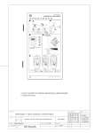
Document: MS02210211 R1.0 IADS-PROG IADS Connection Hub User Guide EN Part number: MS02210211 Print Instructions A5 8 pages manual Booklet Stapled Document size Print size A4 A5 Name Date Mikhail Sleptsov 2011-03-23 Fold to Paper weight Paper colour Ink colour 75gms White Black Property UTC Fire & Security IADS-PROG IADS Connection Hub User Guide Content Description 1 Packaging 2 Prerequisites 2 Setup and connections 2 USB to serial converter mode 3 IADS device programming mode 4 Attributes 6 Specifications 6 Regulatory information 6 Contact information 7 Copyright © 2011 UTC Fire & Security. All rights reserved. Description The IADS-PROG IADS connection hub is designed for the following functions: • It allows to connect computers (notebooks, desktop PCs, etc.) to ATS control panels, creating a bridge between a USB port of the computer and an RS232 connection of the control panel. See “USB to serial converter mode” on page 3 for more details. • It also allows address programming for addressable detectors or other components (for example, magnetic contact type MK 46 AD), which do not provide a physical way of address change. The programming mode allows connecting a detector or component via two-wire cable to a USB port of a computer, which runs an application to monitor the device and to change the corresponding address in an IADS network. See “IADS device programming mode” on page 4 for more details. P/N MS02210211 • REV 1.0 • ISS 23MAR11 1 Packaging The packaging includes the following components: • • • • 1 x User Guide (this document) 1 x USB-A to USB-B connection cable 1 x IADS connection hub CD with the AdDev management application Prerequisites The physical connections are described in the corresponding chapter. The requirements for running the software are: • A free USB port • One of the following operating systems: Windows XP, Windows Vista, Windows 7 There are no administrator requirements. It might be necessary to configure the system or any firewalls / security software to allow access to the USB port. Please be aware that the first version of Titan supporting programmable devices programmed with the IADS connection hub is ATS800301.05.12, however this Titan version supports only certain programmable devices. Setup and connections The IADS connection hub is shown in Figure 1 below. Figure 1: IADS connection hub layout Yellow LED USB to serial converter USB connector Mode button RS232 connector Green LED Programming mode 2 IADS 2-way connector IADS-PROG IADS Connection Hub User Guide • The RS232 plug can be connected with an RS232 cable (male — male, 9-pin connectors) to the ATS control panel. • The IADS 2-way connector can be used for hooking up a sensor / component for addressing. Only one sensor / component is allowed to be connected at any time (brown cable on “+”, black cable on “−“). • Mode button allows toggling between RS232 connection and IADS 2-way connector output. • LEDs show which output a computer is connected to. The yellow LED indicates the USB to serial converter mode, the green LED means IADS device programming mode. • The USB plug is used for hooking up the IADS connection hub to the computer via the USB cable, which is a part of the package. Each time the IADS connection hub has been connected to the USB port of the computer, it powers up and performs an internal self test. If the internal self test has been successfully performed, it automatically switches into IADS device programming mode, and the green LED switches on. In case when a problem occurs during the internal self test, the green and the yellow LEDs blink alternately. In this case, return the IADS connection hub to UTC Fire & Security for verification and maintenance purpose. Avoid detaching the IADS connection hub either from a control panel, a programmable device, or from a PC, when the actual programming or data exchange function is in progress — it can affect correct and successful operation. USB to serial converter mode This mode allows to connect ATS control panels, that currently have a 9-pin RS232 connector, transparently to a computer (usually a notebook), which are mostly equipped only with USB ports. The IADS connection hub should be connected via the USB cable to the notebook, and via a 9-pin RS232 cable to an ATS control panel. Figure 2: USB to serial converter mode USB IADS connetion hub RS232 IADS-PROG IADS Connection Hub User Guide PC ATS panel 3 Press Mode button on the IADS connection hub, so that the yellow LED is on. The IADS connection hub is now in the converter mode. After that, it is possible to connect the Titan software to the ATS control panel, to manage and configure the panel. For further information on programming see appropriate panel programming and management manuals, as well as Titan online help system. IADS device programming mode When using the IADS connection hub in programming mode, use the AdDev software from the supplied CD. You can copy the software to the computer hard disk, or run it directly from the CD. Note: To copy the software, copy the application file AdDev102.exe and the configuration file AdDev.ini into the same directory. No administration privileges are required to copy or run the application. Figure 3: IADS device programming mode IADS connetion hub USB PC two-core cable Point ID contact Connect the IADS connection hub as shown in Figure 3 above. The IADS connection hub should be connected via the USB cable to the computer. Connect a programmable device via two-wire cable to the IADS connection hub, and press Mode button to set the addressing mode, until the green LED is on. Double-click the application file AdDev102.exe to run the software. 4 IADS-PROG IADS Connection Hub User Guide Figure 4: AdDev software interface If necessary, choose the appropriate language from the Language combo box. In the AdDev application, choose a correct COM port, or search through the COM-port list to find the IADS connection hub by pressing Scan Ports. During the start-up the application will scan all ports and search for the IADS connection hub, if connected already. “State” will show a status of the communication with the computer via USB. The following values are possible: • • • Operation successful! Operation failed! No connection! If a device found which is recognized by the application, the device name will be displayed in the field “Device Name” as well as the corresponding attributes and the current address. The state will be “Operation successful”. If no device or an unknown device is connected, the field “Device Name” will show “No device” or “No IADS device”. All other fields will stay blank or 0. Use buttons “Read Device”, Write Device” and “LED toggle” to tested or address the connected IADS device. To change the address of a device, enter a new address, or select it from combo box. Use button Write Device to write a new address. The new address will be then shown in the Current Address field. The allowed address range is from 0 to 31. Other values will be ignored. Remember that each device within each IADS network must have a unique address. Double addressing within the same line is forbidden and can cause unpredictable problems or behaviour. IADS-PROG IADS Connection Hub User Guide 5 Press Read Device button to read and display the device values in fields “Device Name”, “Actual Device”, “Category”, and “Type”. Press Reset button to reset the application. If no device is connected, “Device Name” will show “no device”, and other fields will be blank or 0. If an IADS device is already connected, its settings will be displayed accordingly. Press Close button to close the AdDev application. Attributes The attributes “Open/Close”, “Device Failure” and “LED Toggle” are also shown in the AdDev application. If magnetic contact MK46-AD is attached to the IADS connection hub, the attribute”Open/Close” shows a black box if the contact is closed, or green box if the contact is open. The “Device Failure” box is normally black; it turns to red colour if the magnetic contact has an electric failure, for example, if the device draws current higher than 10 mA, or has a short circuit. Specifications Supply voltage 5 V ±5% (USB powered) Current consumption: Programming mode 90 mA max. Converter mode 31mA Max. devices connected to IADS output 1 Maximum Baudrate in converter mode 250 kbit/s Dimensions (W x H x D) 100 x 60 x 25 mm Regulatory information Manufacturer UTC Fire & Security Americas Corporation, Inc. 1275 Red Fox Rd., Arden Hills, MN 55112-6943, USA Authorized EU manufacturing representative: UTC Fire & Security B.V. Kelvinstraat 7, 6003 DH Weert, Netherlands Certification European Union directives 6 1999/5/EC (R&TTE directive): Hereby, UTC Fire & Security declares that this device is in compliance with the essential requirements and other relevant provisions of Directive 1999/5/EC. IADS-PROG IADS Connection Hub User Guide 2002/96/EC (WEEE directive): Products marked with this symbol cannot be disposed of as unsorted municipal waste in the European Union. For proper recycling, return this product to your local supplier upon the purchase of equivalent new equipment, or dispose of it at designated collection points. For more information see: www.recyclethis.info. Contact information www.utcfireandsecurity.com or www.interlogix.com Customer support www.interlogix.com/customer-support IADS-PROG IADS Connection Hub User Guide 7 8 IADS-PROG IADS Connection Hub User Guide