1
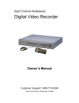
4/8/16CH Triplex DVR
User Guide
INFORMATION MAY CHANGE WITHOUT NOTICE.
Digital Video Recorder
4/8/16CH Triplex DVR
Table of Contents
Caution ........................................................................................................... 6
Package Contents ......................................................................................... 6
Introduction.................................................................................................... 7
1.
Product Overview........................................................................................7
2.
Product Outline ...........................................................................................8
3.
Front Panel...................................................................................................8
3.1. The slim model (4/8CH DVR) .............................................................8
3.2. The removable drive (CD-ROM/DVD-ROM) model (4/8CH DVR) ....9
3.3. 16CH DVR..........................................................................................10
4.
Rear Panel..................................................................................................11
5.
IR Remote Controller ................................................................................14
Installation.................................................................................................... 16
1.
Install the disk drives................................................................................16
1.1. Install the removable disk drive on the front panel.......................16
1.2. Install the internal disk drives (IDE interface) for 4/8CH DVR ......17
1.3. Install the internal disk drives (SATA interface) for 4/8CH DVR ..18
1.4. Install the internal disk drives for 16CH DVR ................................21
2.
USB connector on rear panel...................................................................22
3.
Camera connections .................................................................................23
4.
RS485/RS232 Selection ............................................................................25
4.1. 4 CH Triplex DVR ..............................................................................25
4.2. 8 CH Triplex DVR ..............................................................................25
4.3. 16 CH Triplex DVR ............................................................................26
5.
Video Format Selection ............................................................................27
5.1. 4 CH Triplex DVR ..............................................................................27
5.2. 8 CH Triplex DVR ..............................................................................27
5.3. 16 CH Triplex DVR ............................................................................28
6.
Cablings .....................................................................................................28
6.1. 4 CH Triplex DVR ..............................................................................28
6.2. 8 CH Triplex DVR ..............................................................................29
6.3. 16 CH Triplex DVR ............................................................................29
7.
Sensor Installation ....................................................................................30
7.1. 4 CH Triplex DVR ..............................................................................30
7.2. 8 CH Triplex DVR ..............................................................................30
7.3. 16 CH Triplex DVR ............................................................................31
8.
Alarm Installation ......................................................................................31
Digital Video Recorder
2
4/8/16CH Triplex DVR
8.1. 4 CH Triplex DVR ..............................................................................31
8.2. 8 CH Triplex DVR ..............................................................................32
8.3. 16 CH Triplex DVR ............................................................................32
Start up the DVR System ............................................................................ 33
1.
Commands.................................................................................................34
1.1. Video loss..........................................................................................34
1.2. Operating Buttons ............................................................................34
1.3. Mouse Operating ..............................................................................34
1.4. Icons ..................................................................................................35
2.
Main Menu..................................................................................................37
3.
Channel Setup ...........................................................................................38
3.1. Channel Number...............................................................................38
3.2. Active Channel..................................................................................39
3.3. Record Channel ................................................................................39
3.4. Hidden Channel ................................................................................39
3.5. Channel Name...................................................................................39
3.6. Rotation Time....................................................................................40
3.7. Color Adjustment .............................................................................40
4.
Record Setup .............................................................................................40
4.1. Auto Record ......................................................................................40
4.2. Video Quality.....................................................................................40
4.3. Record Resolution (only for 16CH DVR) ........................................41
4.4. Record Frame Rate...........................................................................41
4.5. Record Schedule ..............................................................................42
5.
Detector Setup...........................................................................................45
5.1. Channel Number...............................................................................45
5.2. Video Loss Alarm .............................................................................46
5.3. Trigger Full Screen...........................................................................46
5.4. Trigger Type......................................................................................46
5.5. Motion Setup.....................................................................................46
5.6. Sensor Setup ....................................................................................48
6.
System Setup.............................................................................................49
6.1. Query Error Message .......................................................................49
6.2. View Setup ........................................................................................49
6.3. Date/Time Setup ...............................................................................52
6.4. Button Beep Setup ...........................................................................53
6.5. Input Device Setup ...........................................................................54
6.6. Auto Exit Menu .................................................................................54
Digital Video Recorder
3
4/8/16CH Triplex DVR
7.
Hardware Setup .........................................................................................54
7.1. Authentication Setup .......................................................................55
7.2. Hard Drive Setup ..............................................................................55
7.3. Network Setup ..................................................................................57
7.4. Screen Setup.....................................................................................61
7.5. Audio Setup ......................................................................................62
7.6. Firmware Update ..............................................................................63
7.7. Load Default Setting.........................................................................65
8.
Exit Main Menu ..........................................................................................65
8.1. Exit & Save Changes........................................................................65
8.2. Exit & Discard Changes ...................................................................65
Playback ....................................................................................................... 65
Data Backup by USB ................................................................................... 68
1.
Backup by USB..........................................................................................69
2.
Backup by CDRW ......................................................................................70
PC Connection through Local Area Network (network hub) ................... 71
1.
Search Router IP Address ........................................................................71
2.
DDNS Service ............................................................................................74
2.1. Registration of DDNS Service .........................................................74
2.2. Create Your DynDNS Account ........................................................75
2.3. Logged In and Host Service ............................................................77
2.4. Router Setting...................................................................................79
2.5. DVR DDNS Setting............................................................................79
2.6. PC Client Setting ..............................................................................79
PC Client & PC Viewer................................................................................. 80
1.
DirectX........................................................................................................80
2.
PC Client/PC Viewer Program Installation ..............................................81
3.
Open Disk Operating in VISTA.................................................................82
4.
PC Viewer Operating Guide......................................................................83
4.1. PC Viewer Operating buttons & Operating mode..........................84
4.2. Playback ............................................................................................85
4.3. Capture ..............................................................................................88
5.
PC Client Operating Guide .......................................................................89
5.1. Connect PC Client to DVR ...............................................................90
5.2. Status information............................................................................91
5.3. Control Icons ....................................................................................92
6.
Name Server ..............................................................................................93
7.
PC Capturing .............................................................................................95
Digital Video Recorder
4
4/8/16CH Triplex DVR
8.
Playback.....................................................................................................98
Remote Surveillance through IE Browser ................................................. 98
Digital Video Recorder
5
4/8/16CH Triplex DVR
Caution
z
z
z
z
z
z
z
z
z
For your safety, unplugging the power before moving the DVR, installing, or
replacing any parts or hard drive.
Make sure all the power cable and wires are properly set up before using the
DVR.
To avoid a short circuit, don’t leave any unnecessary parts inside the DVR.
Please avoid dramatic changes of the environment, such as dust, temperature,
and humidity. Keep the DVR in a temperature ranging from 5℃~40℃.
Keep the DVR in a well-ventilated place and away from any heat-generating
objects.
Do not block the DVR’s fan and vent.
Do not expose this unit to the sun directly.
If you are not sure of the installation and setup, please consult the technicians.
Don’t fix it yourself if there’s any damage to this unit or the power supply,
Consult the technician or the distributor.
Package Contents
z
z
z
z
z
z
z
DVR Main unit x 1
Power Adapter x 1
AC Power Cord x 1
Manual x 1
Software CD x 1
USB Mouse X1
IR Remote Controller x 1
If there is any damage, shortage or inappropriate item in the package, please
contact with your local dealer.
Digital Video Recorder
6
4/8/16CH Triplex DVR
Introduction
1. Product Overview
z
High quality pictures by digital recording with 4/8/16 video inputs (NTSC/PAL)
z
Provides one VGA and S-video/video-in*2 for video output and two audio inputs
z
Triplex operations : Recording / Playback / Remote Backup
z
Two compressive modes: MJPEG (recording) / MPEG4(networking)
z
Individual recording frame rate setting for each channel, from 1fps to real time
z
Individual recording mode by Continuous, Schedule, Sensor/Motion Trigger that
setting for each channel.
z
Search Mode by Time or Event
z
One front accessible R/W DVD-ROM (or accommodated one removable hard
drive) and one internal 3.5” hard drives (optional – IDE to SATA bridge) for 4/8CH
DVR
z
One front accessible R/W DVD-ROM / two internal 3.5” hard drives with IDE or
SATA HDD interface or up to four internal 3.5” hard drives with SATA HDD
interface for 16CH DVR
z
Enhanced USB disk backup
z
One network connection with 10/100 Ethernet(RJ-45)
z
Network protocol by TCP/IP, Static IP, DHCP, PPPoE, DDNS(through
Router)
z
P/T/Z camera control by RS485 (Available soon)
z
Playback searching by Time/Event
z
PC Operating System: Windows XP/2000/Vista
z
Remote monitoring, recording and playback by client program and IE browser
z
Authentication setup function.
z
Mouse / IR remote controller /Front panel keypad operation available
z
Power adapter: Input AC100~240V, 50/60Hz and output is ..
Model \ Output
4/8CH DVR
Slim model/ IDE HDD
+12VDC / 3Amp
Slim model/SATA HDD
+12VDC / 4Amp
w/removable drive & IDE HDD
+12VDC / 4Amp
w/removable drive & SATA HDD
+12VDC / 5Amp
Model \ Output
16CH DVR
w/one DVD-RW & two internal HDD
+12VDC / 6.6Amp
w/four internal HDD (SATA)
+12VDC / 7.5Amp
Digital Video Recorder
7
4/8/16CH Triplex DVR
z
Dimension(Width x Height x Depth):
290x52x220mm (4/8CH DVR with one 3.5”HDD)
340x60x280mm (4/8CH DVR with Removable HDD+3.5”HDD)
430x80x320mm (16CH DVR)
z
Display/Recording frame rate and resolution:
Models
Display Frame Rate
4CH DVR
120/100fps
8CH DVR
240/200fps
16CH DVR
480/400fps
Recording Frame Rate 60(NTSC)/50(PAL)fps 60(NTSC)/50(PAL)fps 120(NTSC)/100(PAL)fps
Display Resolution
640x448 (NTSC) / 640x544(PAL)
Recording Resolution
640x224(NTSC) / 640x272(PAL)
2. Product Outline
3. Front Panel
3.1. The slim model (4/8CH DVR)
-with one internal HDD
(Type I)
Digital Video Recorder
8
4/8/16CH Triplex DVR
(Type II)
(Type III)
3.2. The removable drive (CD-ROM/DVD-ROM) model (4/8CH DVR)
-with one front-accessible disk drive (or CD-ROM/DVD-ROM) and one
internal HDD
Digital Video Recorder
9
4/8/16CH Triplex DVR
3.3. 16CH DVR
Controls:
No.
Name
Function
1
WW REW
Backward search through a time-shifted or recorded video.
2
II/X PLAY/PAUSE
Start or pause video playback
3
XX FF
Forward search through a time-shifted or recorded video.
4
STOP
Stop playback or backup.
5
● REC
Start or stop recording/backup.
6
MODE
Press to select 1/4(1/4/8 for 8ch) screen display.
7
MENU
Enter menu or back to previous menu list..
8
Ç / SUP
Moves up through the list of menu. Also used to select menu
options or change the DVR configuration values.
9
È / T DOWN
Moves down through the list of menu. Also used to select
menu options or change the DVR configuration values.
10
SELECT/ENTER Use this button to change values on main menu or sub menu
setting.
15
II PAUSE
Pause video playback
16
IIX PLAY
Start video playback
17
Press to select full screen display (CH1~CH8)
Full Screen
18
Press to select full screen display (CH9~CH16)
Full Screen
19
2x2 4 Split View
Press to select 4 split view on screen display. With a
sequence of CH1~CH4,CH5~CH8,CH9~CH12, CH13~CH16
20
3x3 9 Split View
Press to select 9 split view on screen display. With a
sequence of CH1~CH8, CH9~CH16
21
4x4 16 Split View
Digital Video Recorder
Press to select 16 split view on screen display as CH1~CH16
10
4/8/16CH Triplex DVR
Indicators:
No.
Name
Function
11
Power LED
The DVR unit is powered up and running. (Green color)
12
Hard disk
LED indicator flashes at hard disk is acting (Red color)
Actived LED
I/O:
No.
Name
13
IR Receiver
14
Function
USB
IR Control receiver (Refer to IR Remote Controller)
Connects PC for firmware upgrading/USB backup
4. Rear Panel
4 CH Triplex DVR (with Removable Disk Drive)
4 CH Triplex DVR (without Removable Disk Drive)
Digital Video Recorder
11
4/8/16CH Triplex DVR
8 CH Triplex DVR (with Removable Disk Drive)
8 CH Triplex DVR (without Removable Disk Drive, without Sensor/Alarm)
16 CH Triplex DVR
Digital Video Recorder
12
4/8/16CH Triplex DVR
No.
Function
1
IR Extender connector (Optional)
2
VGA Display Connector (DB-9)
3
AUDIO-IN
4
POWER ON/OFF Switch
5
USB PORT (dedicated Only for Mouse Connection, must connect at the
beginning of Power On)
6
S-VIDEO
7
VIDEO OUT (Monitor)
8
VIDEO IN (BNC)
9
General Purpose I/O for SENSOR/ALARM/RS485
10
DC-IN (12V)
11
AUDIO-OUT
12
LAN (RJ45)
13
NTSC/PAL SELECTOR
14
SPOT MONITOR
Digital Video Recorder
13
4/8/16CH Triplex DVR
5. IR Remote Controller
No
Button / Name
Function
1
REC
2
z DVR
3
z PTZ
4
WW REW
Backward search through a time-shifted or recorded video.
5
STOP
Stop playback or backup.
6
II PAUSE
Pause recording or playback.
7
XX FF
Forward search through a time-shifted or recorded video.
8
► PLAY
Start video playback.
9
MENU
Enter menu or exit.
10
▲(UP)/ ▼(DOWN)/
Moves up/down/left/right through the list of menus. Or use
W (LEFT)/ ►(RIGHT)
it to select / change the DVR configuration values.
(Enter/Select)
Use this button to change or confirm values on main menu
11
Start or stop recording / backup.
N/A
Switch to PTZ mode (Available soon).
or sub menu setting.
12
13
14
4 AUTO
MODE
- ZOOM OUT
Digital Video Recorder
Press AUTO button to start screen auto sequence.
Back to 4/8 (for 4/8ch) screen display while screen is full..
N/A
14
4/8/16CH Triplex DVR
15
16
+ ZOOM IN
1,2,----16 (Channels)
Digital Video Recorder
N/A
Channels Selector (CH1~CH16 depends on each DVR)
15
4/8/16CH Triplex DVR
Installation
Be sure there is no power connection before starting installation!
1. Install the disk drives
There are two spaces for disk drives installation on the DVR: One front accessible R/W
CD-ROM/DVD-ROM (or removable HDD drive) and one internal 3.5” hard drives with
IDE (default) or SATA interface.
Set the HDD (installed with OS/DVR software) jumper into “Master” to make sure all
operating will be normal. The other HDD would be set to “Slave”.
1.1. Install the removable disk drive on the front panel
Step1: Unlock the removable disk drive and slide out the HDD tray.
Step2: Remove the HDD tray’s cover. Put one HDD drive into the tray and
well-connect the cable to HDD drive on the rear side of the tray.
Setp3: Fix four screws on both sides, put the cover back and slide back the HDD
tray.
Digital Video Recorder
16
4/8/16CH Triplex DVR
1.2. Install the internal disk drives (IDE interface) for 4/8CH DVR
Step1: Unscrew three screws on DVR’s rear panel. Then slide backward the
chassis’s top cover and move it upward
Step2: Fix the hard drive
The Slim Model (4/8 CH DVR)
Put the HDD into the HDD bracket and fixed two screws on each side. Plug in the
HDD cable and power line for using.
Digital Video Recorder
17
4/8/16CH Triplex DVR
The removable drive (CD-ROM/DVD-ROM) model (4/8CH DVR)
Unscrew two screws HDD bracket near to the front panel. Slide it forward to rear
side to take the HDD bracket and install 3.5” HDD drives on the top. Plug in the
HDD cable and power line for using
Then, Put the chassis’s cover back
1.3. Install the internal disk drives (SATA interface) for 4/8CH DVR
It needs an IDE to SATA Bridge (Optional) to transfer IDE interface into SATA
before starting to install the hard disk,
Step 1: Place the IDE to SATA Bridge into DVR main unit.
Unscrew three screws on DVR’s rear panel. Then slide backward the chassis’s
top cover and move it upward.
Digital Video Recorder
18
4/8/16CH Triplex DVR
Step 2: Place the IDE to SATA Bridge lodge in DVR main board as following:
Step 3: Make sure the jumpers on IDE to SATA bridge (JS2) have been set to
P1,2-short and P3,4-short as following
Digital Video Recorder
19
4/8/16CH Triplex DVR
Step 4: Unscrew two screws HDD bracket near to the front panel. Slide it forward
to rear side to take the HDD bracket and install 3.5” HDD drives on the top
Then, Put the chassis’s cover back
OR
Digital Video Recorder
20
4/8/16CH Triplex DVR
1.4. Install the internal disk drives for 16CH DVR
16CH DVR provides PATA (IDE) and SATA interface both. Put the HDD into
HDD bracket and fix it by screws. Then, install the whole HDD set into DVR.
<For two HDD installation>
<For one HDD installation>
Digital Video Recorder
21
4/8/16CH Triplex DVR
There are two models for 16ch DVR: 1) Four internal 3.5” hard drives with SATA
interface. Or 2) One front accessible R/W DVD-ROM and one internal 3.5” hard
drives with PATA (IDE) or SATA interface as following figure.
2. USB connector on rear panel
USB connector on rear panel is dedicated for USB mouse using.
Do not connect to any other USB device except the mouse.
Digital Video Recorder
22
4/8/16CH Triplex DVR
3. Camera connections
There are 4/8/16 channels for cameras’ connections named CH1, CH2, CH3 …. CH16.
Each camera has two wirings basically: BNC and Power.
Connect the BNC cable to DVR’s “VIDEO-IN” connector on rear panel for video signals
and connect the power cable to the camera’s power adapter.
Digital Video Recorder
23
4/8/16CH Triplex DVR
The Dome camera has one more RS485 wiring for activity control. At first, please refer
to the next section for setting JS1 selection to RS485 (default is RS232).
Please refer to the following figure and connect to DVR’s “RS485 connectors” (Two
pines) on rear panel for controls signal.
Digital Video Recorder
24
4/8/16CH Triplex DVR
4. RS485/RS232 Selection
The DVR provide one com port. It can be selected to RS232 or RS485 by setting the
jumper on the main control board.
4.1. 4 CH Triplex DVR
Open the top cover as mentioned; there is a main control board with JS1: the
jumper setting to select RS485 or RS232 as following figure.
4.2. 8 CH Triplex DVR
Open the top cover as mentioned; there is a main control board with JS1: the
jumper setting to select RS485 or RS232 as following figure.
Digital Video Recorder
25
4/8/16CH Triplex DVR
4.3. 16 CH Triplex DVR
Open the top cover as mentioned; there is a main control board with JS53: the
jumper setting to select RS485 or RS232 as following figure.
Digital Video Recorder
26
4/8/16CH Triplex DVR
5. Video Format Selection
The DVR accepts two video formats: NTSC and PAL. It can be select by setting the
jumper on the main control board.
5.1. 4 CH Triplex DVR
Open the top cover as mentioned; there is a main control board with JS2: the
jumper setting to select NTSC or PAL for video format as following figure.
5.2. 8 CH Triplex DVR
There is a Video format selector on the rear panel as following figure.
Digital Video Recorder
27
4/8/16CH Triplex DVR
5.3. 16 CH Triplex DVR
There is a Video format selector on the rear panel as following figure.
6. Cablings
Before starting to use, you have to connect all the peripherals like LCD display,
cameras … as following figure:
6.1. 4 CH Triplex DVR
Digital Video Recorder
28
4/8/16CH Triplex DVR
6.2. 8 CH Triplex DVR
6.3. 16 CH Triplex DVR
Digital Video Recorder
29
4/8/16CH Triplex DVR
7. Sensor Installation
The DVR unit can be connected up to 4/8 sensor inputs as following figure.
Each set of sensor has two lines: signal and ground in order to sense the sensor’s
status.
7.1. 4 CH Triplex DVR
7.2. 8 CH Triplex DVR
Digital Video Recorder
30
4/8/16CH Triplex DVR
7.3. 16 CH Triplex DVR
8. Alarm Installation
The DVR unit provides one alarm (speaker) signal. Please connect the alarm system
as following figure.
8.1. 4 CH Triplex DVR
Digital Video Recorder
31
4/8/16CH Triplex DVR
8.2. 8 CH Triplex DVR
8.3. 16 CH Triplex DVR
Digital Video Recorder
32
4/8/16CH Triplex DVR
Start up the DVR System
After the unit is properly installed, the DVR unit is ready to record and play. Then apply
power by turn on the power switch.
After the unit is powered on, the unit will check HDD for several seconds, and then the unit
will enter into real-time display mode shown as the following screen:
Digital Video Recorder
33
4/8/16CH Triplex DVR
1. Commands
1.1. Video loss
If the display shows “VIDEO LOSS-CHx”, it means there is no video signal input.
Please make sure the video cable and camera are well installed.
1.2. Operating Buttons
: Press it to enter the main menu or and exit the menu.
i / j (K / L): Up / Down – To move up/down through the list of menu. Also used
to select menu options or change the DVR configuration values.
/(/): Left/Right – To move left/right through the list of menu.
↵: Select / Enter - To Enter menu list or select DVR configuration values
1.3. Mouse Operating
Digital Video Recorder
34
4/8/16CH Triplex DVR
State Information
There are state informations on the upper of the screen to show the system status .
: Camera on line.
: Camera signal loss
: Recoding
: Stop Recording
: Network acting
: Network no connection
: CD / CDRW
: HDD Status
: 1st Hard drive
: 2nd Hard drive
: USB disk
: Overwrite the hard drive when Hard drive is full.
XX%: Recording Capacity of Hard drive (show by %)
2007/12/25: Date
18:25:31: Time
: Channel Rotation
1.4. Icons
There is a control bar with several icons will display by press “↵” (Select) or move
the cursor down
(4ch DVR for example)
(8ch DVR for example)
(16ch DVR for example)
Digital Video Recorder
35
4/8/16CH Triplex DVR
: : 4 Split View (4ch dvr)
: : 9 Split View (8ch dvr)
: 16 Split View (16ch DVR)
: Auto channel rotation (from 1~4 /1~8 /1~16)
: Start recording
: Stop recording
: Enter Main menu
: Play menu(Playback), To play the recorded data.
: Archive Menu, To save the configuration (Available Soon)
: Event search. To search the events
: Pan/Tile/Zoom Control. To control the P/T/Z camera
: Record Information
: Hard drive Information
: Network Information
Digital Video Recorder
36
4/8/16CH Triplex DVR
2. Main Menu
Press to enter the “main menu”, it will show the password input inquiry as following.
Please enter six numbers by controls on front panel (by using /{/) and ↵) or
the buttons (number 1~16) on IR remote. Default password is “123456”.,
ESC/Discard: To escape this menu by only using USB mouse
After enter the main menu password, it goes into the main menu for DVR setup
(4/8CH DVR)
(16CH DVR)
♦
Channel Setup: To select or specify the channel for display/record.
♦
Record Setup: To setup recording status of the channel which has been selected
at “Channel Setup”.
♦
Detector Setup: To select the channel would like to be detected. Also to setup all
the detection/sensor status.
♦
System Setup: To setup the DVR system configuration including of date/time,
button beep, input device speed ....etc.
Digital Video Recorder
37
4/8/16CH Triplex DVR
♦
Hardware Setup: To update the firmware and to setup the input/output device
configuration such as disk drive, network, display and audio
♦
Exit Main Menu: To exit the main menu
3. Channel Setup
Press to enter the “Channel setup” as following.
(4CH DVR)
(8CH DVR)
(16CH DVR)
3.1. Channel Number
To select or specify the channel for displaying/recording.
” / / ” (default) (Full screen mode): you can view / record all channels (4 or
8 or 16) on the screen of full-screen.
“1,2,3,4” or “1,2,3,4,5,6,7,8” or “9,10,11,12,13,14,15,16”: you can view / record
each channel (4 or 8) be selected on the screen.
Digital Video Recorder
38
4/8/16CH Triplex DVR
3.2. Active Channel
To set the channel been selected at “Channel Number” to both display on screen
and record or not.
“ON” – Display on screen, Channel Number color turns to red
“OFF”- No display on screen. Channel Number color turns to white
It can be setup each channel separately by choosing the dedicated channel at
“Channel Number”. Or to choose ”
/
/
” for all channels
3.3. Record Channel
To set the channel been selected at “Channel Number” to be recorded or not.
“ON” – recording, “OFF”- No recording.
It can be setup each channel separately by choosing the dedicated channel at
“Channel Number”. Or to choose ”
/
/
” for all channels.
3.4. Hidden Channel
Set the channel been selected at “Channel Number” to display on screen or not.
But it does not matter with recording mode.
“ON” – Hidden the channel on screen you choose, Channel Number color turns
to grey. The recording function is acting.
“OFF”- Not hidden
It can be setup each channel separately by choosing the dedicated channel at
“Channel Number”. Or to choose ”
/
/
” for all channels
3.5. Channel Name
To specify the channel name with 24 characters (max.)
Press “X” (Play) :There are several channel name: “Room”, Hall”, ” Door”, “Lift”,
“Area”, “Floor”, “Entry”, “Point” for use.
Or you can define the name by using keyboard, controls on front panel or buttons
on IR remote: i / j (K / L) – move up / move down, /(/): move left /
move right to the character would like to be selected and press ”↵” to select as
shown at following figure The channel name will show on the top of the Channel
Number.
Digital Video Recorder
39
4/8/16CH Triplex DVR
3.6. Rotation Time
To setup how long to display each channel on full screen from 2~30sec.
3.7. Color Adjustment
To setup the video quality of display.
♦
Brightness: Press “↵” button to change (1~20). Default is 10
♦
Contrast: Press “↵” button to change (1~20). Default is 10
♦
Hue: Press “↵” button to change (1~32). Default is 16
♦
Saturation: Press “↵” button to change (1~32). Default is 16
4. Record Setup
Press to enter the “Record setup” as following.
(4/8CH DVR)
(16CH DVR)
4.1. Auto Record
To setup the recording time period by 0sec(OFF), 10sec, 20sec, 30sec, 40sec,
50sec or 60sec.
Auto record will help you to re-start the recording automatically in case of
abnormal shut down.
4.2. Video Quality
There are three different image video quality settings: NORMAL, LOW, HIGH.
Default is NORMAL. Higher the video quality is the clearer images the unit plays.
But occupy larger recording size on HDD.
Digital Video Recorder
40
4/8/16CH Triplex DVR
4.3. Record Resolution (only for 16CH DVR)
There are two record resolution for setting: Half D1 60FPS & CIF 120FPS
Default is Half D1 60FPS.
Half D1: 640 × 224 for NTSC systems and 640 × 272 for PAL systems
CIF: 320 x 224 for NTSC systems and 320 x 272 for PAL systems
4.4. Record Frame Rate
Setup the recording frame rate for each channel.
(4CH DVR)
(8CH DVR)
(16CH DVR)
4.4.1. Auto Balance
To setup all channel recording frame rate and keep each channel’s frame
rate in balance.
When Trigger mode is ON, the active channel has been detected will occupy
all record frame rate.
Digital Video Recorder
41
4/8/16CH Triplex DVR
4.4.2. Record Total Frame Rate
To setup each channel’s recording frame rate in separately.
For 4ch DVR, Total frame rate is 60/60FPS (Frame Per Second), each
channel is 15fps in balance as default.
For 8ch DVR, Total frame rate is 56/60FPS (Frame Per Second), each
channel is 7fps in balance as default.
For 16ch DVR, Total frame rate is 112/120FPS (Frame Per Second), each
channel is 3fps in balance as default.
4.5. Record Schedule
To setup the recording schedule during one week from Sunday to Saturday
Each day is 24-hour.
♦
Channel Number
To setup the channel recording schedule.
” / / ”: All channels will be set at the same recording schedule.
“1,2,3,4” or “1,2,3,4,5,6,7,8” or “9,10,11,12,13,14,15,16”: To setup each
channel recording schedule.
♦
Recording Mode Select
Digital Video Recorder
42
4/8/16CH Triplex DVR
There are five recording modes for selection: None, Time, Motion, Sensor and
Motion&Sensor.
“/(/)” : To move left or right,
“” :To select the mode.
None
: Recording is off during this duration.
Time
: Indicates to record by time schedule
Sensor
: Indicates to record by sensor trigger. It means the unit starts recording
as the attached sensors being triggered during this period.
Motion
: Indicates to record by motion detection.
Motion&Sensor
: Indicates to record by both motion detection and sensor
trigger..
♦
Recording Schedule
“/(/)” : To move left or right.
“” :To select the mode.
“(Ç/È)”: To move up or down.
To set all 7-days /24hous at the same configuration by select “”
For example, choose “Motion” mode for all 7-days by move to “” and press”””:
Digital Video Recorder
43
4/8/16CH Triplex DVR
To set one whole day at the same configuration by select “X”
For example, Sunday is set to “Sensor” mode and Saturday to “Motion mode”
To set the specified time for each day at the same configuration by select “T”
For example, the time frame 23:00-24:00 is set to “Sensor” mode for whole week.
Digital Video Recorder
44
4/8/16CH Triplex DVR
To set any time (by hour) for each day, just move to the desired daytime and
select after setting the desired recording mode
For example, “Motion” mode at Sunday 19:00~24:00 and Tuesday 2:00~4:00 as
following
5. Detector Setup
This menu is to adjust the motion detection sensitivity of each channel
5.1. Channel Number
To select or specify the channel for detection.
” / / ” (default) (Full screen mode): you can detect all channels (4/8/16) on
the screen of full-screen
“1,2,3,4” or “1,2,3,4,5,6,7,8” or “9,10,11,12,13,14,15,16”: you can detect each
channel (4/8/16) be selected on the screen
Digital Video Recorder
45
4/8/16CH Triplex DVR
5.2. Video Loss Alarm
To select or specify the channel for detection.
“Mute”: No beep whatever video loss or not.
“
Buzzer-Short”: Beep shortly by buzzer on main board when video loss.
“
Buzzer-Long”: Beep long by buzzer on main board when video loss.
“
Alarm-Short”: Beep shortly by speaker of system when video loss.
“
Alarm-Long”: Beep long by speaker of system when video loss.
5.3. Trigger Full Screen
To display the trigger channel on full screen when it act as 1sec, 2sec … or
30sec.
“ OFF” : It will not display on full screen when the channel has been triggered.
Also, the trigger area will turn to “red-color”
5.4. Trigger Type
There are two trigger types: “Initial Trigger” and “Continuous Trigger” for selection.
Initial Trigger: When channel has been triggered, it will display on full screen as
the setting time period. In that time period, this channel will ignore any other
trigger.
Continuous Trigger: When channel has been triggered, it will display on full
screen as the setting time period. In that time period, this channel is still watching
out. If another trigger act, the channel will display on full screen and count all over
again by the setting time period.
5.5. Motion Setup
To setup motion detector configuration
5.5.1. Motion Mode
To select the motion sensitivity scale as “Sensitive OFF”, “Sensitive Low”,
“Sensitive Normal”, “Sensitive High” or “Sensitive Highest”.
“Sensitive OFF”: No sensitivity
“Sensitive Low”: Low sensitive level
“Sensitive Normal”: Normal sensitive level
“Sensitive High”: High sensitive level
“Sensitive Highest”: The highest sensitive level
Digital Video Recorder
46
4/8/16CH Triplex DVR
5.5.2. Record Time
To set the motion’s record time as 5sec, 10sec, 15sec, 20sec, 25sec,
30sec, 45sec, 60sec, 90sec, 120sec, 150sec or 180sec
5.5.3. Alarm Mode
To set the motion detector alarm mode.
“Mute”: No beep whatever detecting.
“
Buzzer-Short”: Beep shortly by buzzer on main board when
detection is active
Buzzer-Long”: Beep long by buzzer on main board when detection
“
is active
Alarm-Short”: Beep shortly by speaker of system when detection is
“
active
Alarm-Long”: Beep long by speaker of system when detection is
“
active
5.5.4. Alarm Time
To Setup the time period of beep by “Nonstop”(no stop), 5sec, 10sec,
15sec, 20sec, 25sec, 30sec, 35sec, 40sec, 45sec, 50sec, 55sec or 60sec
5.5.5. Motion Area Setup
Block one area on screen for each channel as motion detection area.
It can be done by mouse or by using c(u), d(v), __ (W), ``(X) buttons
(up/down/left/right) to move the area. After positioning, press “” and
save it
Digital Video Recorder
47
4/8/16CH Triplex DVR
5.6. Sensor Setup
5.6.1. Sensor Mode
To set the sensor mode as “Not Installed”, “Normal-Open” or
“Normal-Close”.
5.6.2. Record Time
To set the sensor’s record time as 5sec, 10sec, 15sec, 20sec, 25sec,
30sec, 45sec, 60sec, 90sec, 120sec, 150sec or 180sec.
5.6.3. Alarm Mode
To set the motion detector alarm mode.
“Mute”: No beep whatever detecting.
“
Buzzer-Short”: Beep shortly by buzzer on main board when
detection is active
Buzzer-Long”: Beep long by buzzer on main board when detection
“
is active
Alarm-Short”: Beep shortly by speaker of system when detection is
“
active
“
Alarm-Long”: Beep long by speaker of system when detection is
active
5.6.4. Alarm Time
To Setup the time period of beep by “Nonstop”(no stop), 5sec, 10sec,
15sec, 20sec, 25sec, 30sec, 35sec, 40sec, 45sec, 50sec, 55sec or 60sec
Digital Video Recorder
48
4/8/16CH Triplex DVR
6. System Setup
To set up the Password, time, date and button beep…etc.
6.1. Query Error Message
The listing of DVR error message.
“ ” : Show error message with time
“X” : Clear all error messages.
6.2. View Setup
To setup the illustration and DVR information will be displayed or not.
Digital Video Recorder
49
4/8/16CH Triplex DVR
6.2.1. Icon Help
“ON” - Icon help will be shown,
“OFF” –Icon help will not be shown
Please refer to 1.5 Icons for more detail information
6.2.2. Error Message Information
“9ON” - Save/display the error message
“XOFF” – Without save/Display the error message
6.2.3. State Information
System status information, it includes record light, network information,
hard drive information, date/time information and rotate information. All
information can be set separately to be seen or not.
Please refer to 1.4 State Information for more details.
Digital Video Recorder
50
4/8/16CH Triplex DVR
6.2.4. Channel Information
Channel information includes channel number, channel name, record light,
video loss, record mode, detector mode and alarm view. All information
can be set separately to be seen or not.
.
,
,
,
,
,
,
,
,
,
,
,
,
,
,
: Channel
Number
: Recording status
: Video Signal Status
: Detection mode and status (Flash if sensor has been triggered)
: Alarm Active
Digital Video Recorder
: Buzzer active
51
4/8/16CH Triplex DVR
6.3. Date/Time Setup
To setup the date and time
6.3.1. Date View Mode
To display the date/time format on state information by DD/MM/YYYY,
MM/DD/YYYY or YYYY/MM/DD. (YYYY-Year, MM-Month, DD-Day)
6.3.2. Time Set
To setup the day / time.
i / j (K / L): Up / Down – Change the number
/(/): Move left/right to the character that need to change
: Exit after confirmed setting
6.3.3. Time Zone
To set the time zone where you are located.
6.3.4. Daylight Saving Time
To set daylight saving time period by specify the Month, Week, Day and
Hour
Digital Video Recorder
52
4/8/16CH Triplex DVR
6.3.5. NTP Server
Synchronize DVR day/ time to NTP server through internet.
♦ Server Active: “9Enable”-To set this function available. ” X Disable”- Ignore
this function
♦ Server IP: The IP address of NTP server
♦ Interval (Days): Set how many days to synchronize
♦ Synchronize Now: Select it to start Synchronizing the NTP server
6.4. Button Beep Setup
To setup the beep type when press the button of mouse, keypad or IR remote.
There are four modes: mute, sound A, sound B, sound C
Digital Video Recorder
53
4/8/16CH Triplex DVR
6.5. Input Device Setup
To setup the speed of input device: mouse, mouse repeat, keypad and IR
remote as Low, normal or fast
6.6. Auto Exit Menu
To setup the time period to exit menu automatically by choose “OFF” (not exit
unless pressing “”), 10sec, 20sec, 30sec, 40sec, 50sec or 60sec.
7. Hardware Setup
Press to enter the “Hardware Setup”.
Digital Video Recorder
54
4/8/16CH Triplex DVR
7.1. Authentication Setup
Specify the limits of authority of user and set its own password.
“IIX”: To create a new account.
“”: To delete account.
“__ (W), ``(X)” Set account within certain limits by set it as “9” or no permitted as “X”
(Account Active): The account is active
(Account Disable): The account is not active
Account ID (account name): Enter characters as account ID
Passwd (Password): By entering six characters or numbers as password.
The password will replace by “******” when any user login from network.
Remark:
♦
If all accounts are disabled or no account has been created, there is no authority
issue for the DVR system
♦
If one function has been disable for all users. It means that function do not need
password for setting.
7.2. Hard Drive Setup
To set up the hard drive information and overwriting function
7.2.1. Overwrite enable
“9YES”: Enable to overwrite hard drive when capacity is full
“X NO”: Not permit to overwrite hard drive when capacity is full.
Digital Video Recorder
55
4/8/16CH Triplex DVR
7.2.2. Hard Disk Info Summary
All hard drive Information in summary
y Record Begin Time: The starting day/time of hard drive recording
y Record End Time: The latest day/time of hard drive recording
y Standard Record Size: The recorded Capacity / Total hard drive
capacity by Mega-byte. Also show up the % of how much capacity has
been used.
y Standard Event Quantity: The capacity has been record of event /
Total capacity for event.
7.2.3.
Master Hard Disk
The Mater hard drive Information in summary
y Model: Model of master hard drive.
y Record Begin Time: The starting day/time of hard drive recording
y Record End Time: The latest day/time of hard drive recording
y Standard Record Size: The recorded Capacity / Total hard drive
capacity by Mega-byte. Also show up the % of how much capacity has
been used.
y Standard Event Quantity: The quantity has been record of event /
Total quantity for event.
y Format Hard Drive: To format the hard drive. If the system is running
at recording mode, it is not permitted to format the hard drive and show a
warning …
Digital Video Recorder
56
4/8/16CH Triplex DVR
7.3. Network Setup
To set up Network configurations
7.3.1. Network Active
Enable/disable the network before use.
“ 9 Enable” : Network is permitted to be used
“ X Disable” : Network is not permitted to be used
7.3.2.
Accept Client
“9YES” to enable the network client function.
“X NO” means there is no network client available.
7.3.3.
Video Transmission Quality
Setup the quality of Video Transmission as High, Normal or Low.
7.3.4. Audio Transmission
“9ON” : Enable the audio transmission.
“X OFF”: Disable the audio transmission
7.3.5. Port
Assign a communication port (a series of number).
7.3.6. IP Address Setup
The IP address acts as a locator for one IP device to find another and
interact with it.
Digital Video Recorder
57
4/8/16CH Triplex DVR
There are two kinds IP types: Static IP address and Dynamic IP address
(DHCP and PPPoE) for selection.
♦ Static IP Address: When a computer uses the same IP address every
time it connects to the network, it is known as a Static IP address
Static IP addresses are manually assigned to a computer by an
administrator
♦ DHCP: With dynamic IP addresses, where an IP address is
automatically assigned to a computer by a remote server which is acting
as a Dynamic Host Configuration Protocol (DHCP) server
♦ PPPoE: Dialup and some broadband networks do not use DHCP, but
instead use the dynamic IP addressing capability of the Point-to-Point
Protocol over Ethernet.
♦ GATEWAY: Gateway IP address, please check with your M.I.S staff or
administrator to enter the setting.
♦ SUBNET MASK: Subnet mask is a range of logical addresses that is
assigned to an organization. Please check with your M.I.S staff or
administrator to enter the setting
♦ MAC Address: It is a number that acts like a name for a particular
network adapter. It has been set at dedicated address even reset the
DVR.
7.3.7. Server Setup
To setup the server configuration.
Digital Video Recorder
58
4/8/16CH Triplex DVR
♦ Default DNS Address: The Domain Name system (DNS) translate
hostnames to IP addresses (default setting)
If there is no customer DNS address setting or fail, DVR will go for Default
DNS Address.
♦ Custom DNS Address: The Domain Name system (DNS) translate
hostnames to IP addresses (customer setting).
♦ WEB Server: DVR WEB Server response the requests from browsers, and
serve remote monitoring through IE Browser.
“Service Active”: Enable the Web Server service.
“Port”: Assign a port as the Web Server
“Upload IE ActiveX File”: Upload Active-X component to DVR for PC (IE
Browser) using.
To get Active-X component from CD as attached and save it into USB disk.
Then plug the USB disk into DVR for installation.
Digital Video Recorder
59
4/8/16CH Triplex DVR
♦ Dynamic DNS: Dynamic DNS is a system which allows the domain name
data held in a name server to be updated in real time.
“Service Active”: Enable the Dynamic DNS service.
“Provider”: The web site / IP Address of Dynamic DNS provider
“Server Name”:
To define a name of Dynamic DNS
“Account”: The account name of Dynamic DNS
“Password”: Password for Dynamic DNS
Please refer to DDNS Service
♦ Name Server: Name Server implements a name-service protocol. It will
normally map a human-recognizable identifier (such as domain name) of a
host to its computer-recognizable identifier (such as IP address).
“Service Active”: Enable the Name Server
“DVR ID on LAN”: The DVR ID on LAN (define a name of DVR)
“IP Address”: IP address of Name Server (refer to Name Server information)
“Port”: The Port of DVR on LAN
“Update Interval”: Time period to update data.
Digital Video Recorder
60
4/8/16CH Triplex DVR
7.4. Screen Setup
To set the screen information
7.4.1. Screen Border
“9ON” : To enable the border of screen,
“X OFF”: To disable the screen border.
7.4.2. Video Adjustment
Adjust the whole picture to right/left or up/down by press /(/)
or i / j (K / L). “
/
Digital Video Recorder
/
” : Set it as default location
61
4/8/16CH Triplex DVR
7.4.3. VGA Resolution
To choose the resolution of VGA as 640x480, 800x600, 1024x768 or
1280x1024.
7.5. Audio Setup
To setup the audio status including of audio record, audio mute, input volume
and output volume.
7.5.1. Audio Record
“9ON”: Enable audio recording.
“X OFF”: Disable audio recording
7.5.2. Audio Mute
“9ON”: Switch on the audio function
“X OFF”: Switch off the audio function
7.5.3. Input Volume
Adjust the input volume of audio
“X OFF”: Turn off the audio input volume
“1,2,3,4…….10”: Audio input volume from small to aloud.
7.5.4. Output Volume
Adjust the output volume of audio
“X OFF”: Turn off the audio output volume
“1,2,3,4 …….10”: Audio output volume from small to aloud.
Digital Video Recorder
62
4/8/16CH Triplex DVR
7.6. Firmware Update
To update or upgrade the DVR firmware by USB disk..
Plug the USB disk into USB port on DVR front panel
Plug the USB disk into USB port on DVR front panel
After plug in USB disk, it shows” Read file Information” on the button line
If something mistake for USB disk or file, it will show: File not found or Disk
Error on the button line. Please check USB disk or file and plug in again.
Digital Video Recorder
63
4/8/16CH Triplex DVR
After complete the firmware reading, it shows “ Update Process” and blanking
on the button line as following. Also, the updated firmware information will be
listed.
Press “
” to start the procedure of firmware update
When DVR is updating the firmware, it shows “Firmware is updating, Please
wait”
After firmware update is completed, it will show: Firmware update is success,
System will restart ----“ and restart DVR with the same configuration at previous
version firmware does.
Digital Video Recorder
64
4/8/16CH Triplex DVR
7.7. Load Default Setting
To reset all the DVR configuration as default setting.
8. Exit Main Menu
To exit menu and save / discard the changes.
8.1. Exit & Save Changes
To Exit menu and save all configuration changes.
8.2. Exit & Discard Changes
To exit menu but without saving the configuration changes.
Playback
Press “X” (or “IIX”) button to enter the Play Menu
Digital Video Recorder
65
4/8/16CH Triplex DVR
♦ HardDrive Select: To select or specify which hard drive’s data will be playback.
♦ Channel Select: To setup or specify which channel’s data will be playback
♦ Play Begin Time: To specify the beginning time to playback
♦ Play End Time: To specify the beginning time to playback.
The other area shows the recorded data for choosing to play.
Option: Window switching as following
Play: Start to play the recorded data After the data has been played, it will show “9”
Backup: To backup the recorded data. Please refer to “Backup” section
Commands and Recorded Data status:
Digital Video Recorder
66
4/8/16CH Triplex DVR
♦
S/N of Recorded Data: Series Number of recorded data provide by system
♦
Recording Configuration
: The beginning / end of recorded data.
/
: The dedicated hard disk data
: The recording mode
: The data can be play.
If this icon does not show up, it means it is an event without video recording data.
♦
Recording Time: The date/time of recorded data
♦
Status
9 : The recorded video data has been played.
:. Power-OFF event occur.
♦
Searching: A bar to search recorded data by mouse for more convenient.
Digital Video Recorder
67
4/8/16CH Triplex DVR
Data Backup by USB
Press “X” (or “IIX”) button to enter the Play menu.
♦ HardDrive Select: To select or specify which hard drive’s data will be backup
Use “(Ç/È)” button and move to the dedicated recorded data that you want to
backup Press”
” to enter the “Backup Menu” as following.
It shows the backup menu with Disk information on the upper area and the recorded
data that you have selected at “Play Menu” at the lower area.
♦ Hard Drive: It has been selected at “Play Menu” to specify which hard drive’s
data will be backup
♦ Backup Device: System offers two backup device selections: CDRW and USB
disk. CDRW is executable only the DVR is equipped with CDRW.
♦ Free Capacity: System will count the free size of CDRW/USB automatically
after inserting the backup device.
Digital Video Recorder
68
4/8/16CH Triplex DVR
1. Backup by USB
The DVR support the data backup by USB memory stick on the front panel.
You can change the time period of recorded data for backup by setting the “Start Time” and
“End Time” and plug in the USB disk.
The “Free Capacity”, “Estimate Time”, ”Backup Period” and “Backup Size” will be changed
automatically.
Also, it will correct the “Start Time” and “End Time” as the time period which has video
recorded data.
Press “
”, it start to backup data into USB disk.
Digital Video Recorder
69
4/8/16CH Triplex DVR
2. Backup by CDRW
The DVR support the data backup by CDRW.
You can change the time period of recorded data for backup by setting the “Start Time” and
“End Time” and put the CD into CDRW.
All the time setting is the same as USB backup.
CDRW takes more time to backup than USB does.
Digital Video Recorder
70
4/8/16CH Triplex DVR
PC Connection through Local Area Network (network hub)
1. Search Router IP Address
Please click “Start” and then “Run” option under Windows.
Please enter “CMD” and then “OK”
Please enter “ipconfig” on DOS prompt, and then record the Address Number of
Default Gateway as shown: It is the Router’s IP Address.
Digital Video Recorder
71
4/8/16CH Triplex DVR
•
Find out your DVR IP address
Please power off the DVR.
Because this Router IP address is 192.168.11.1,
The network domain is 192.168.11.xxx,
Generally usable IP Address is between 192.168.11.2~192.168.11.253,
The suggested IP Address is from 192.168.11.160 to 192.168.11.199.
Please search IP Address that is not being used at present.
Please enter “ping 192.168.11.188” on DOS prompt (as following figure for reference)
If it appears “Request timed out” messages that means this IP address is not being
used at the moment and can be used for the DVR
Digital Video Recorder
72
4/8/16CH Triplex DVR
If it appears “Reply from 192.168.11.188: bytes=32 time<10ms TTL=128” messages
as following that means this IP Address [192.168.11.188] has been used. Please try to
find out another IP Address that is not being used.
Then, go back to DVR menu: “Network Setup” to enter IP address.
• IP ADDRESS: Enter the DVR’s address [192.168.011.188]
• GATEWAY: Enter Router IP Address[192.168.011.001]
• NET MASK: 255.255.255.0
• PORT: Enter the DVR’s port number [14338 14337]
Digital Video Recorder
73
4/8/16CH Triplex DVR
2. DDNS Service
For DVR only can set at static IP address and no support the dynamic IP. If you have
to use dynamic IP that it recommend serving as DDNS service.
DDNS is a service the maps internet domain names to IP address and works with
dynamic IP address (assigned by ISP server).
Remark: A router is needed as the interface between PC and DVR when DVR is under
internal network environment.
2.1. Registration of DDNS Service
There are three suggestions for DDNS:
www.no-ip.com, www.changeip.com and www.dyndns.com
The following will use DDNS website: http://www.dyndns.com as example.
Create Account at the first beginning after entering DynDNS (DDNS service)
website.
Digital Video Recorder
74
4/8/16CH Triplex DVR
2.2. Create Your DynDNS Account
Click the Create Account, and then start to create your own DynDNS Account
and fill out all the blanks for account’s application as following:
After you click "Create Account", it shows “Account Created”.
Also, DynDNS will create a new account for you and send you an e-mail to the
address you provided. It needs to confirm your account within 48 hours after receiving
the e-mail or it will automatically delete your account.
Digital Video Recorder
75
4/8/16CH Triplex DVR
Just click the https://www.dyndns.com/account/confirm/qMAlozR5sLqNIAyeTCfdAA
To confirm the account
Digital Video Recorder
76
4/8/16CH Triplex DVR
2.3. Logged In and Host Service
Login by enter the Username and password.
Then, go to “My Service” to get a host name
Digital Video Recorder
77
4/8/16CH Triplex DVR
Double click “Add New Hostname” as following:
Specify the Hostname for DDNS IP which will be applied to the DVR’s DDNS
setting.
We take DVR-HOST.dyndns.biz as an example, and click “Create Host”
Digital Video Recorder
78
4/8/16CH Triplex DVR
Now, the DDNS service is completed.
Well keep the User name, Password and Hostname
2.4. Router Setting
Most of the setting of router is identical, here is the suggestion:
y
Specify DDNS service provider: DnyDNS.org (dynamic)
y
Specify DDNS IP by DDNS account (user name / password )
y
Specify DVR IP as private IP setting
y
Specify one pair of connection port (control port / streaming port) , like”8841”
2.5. DVR DDNS Setting
After complete the DDNS account application, go to DVR server setup menu and
input the DDNS information for network connection.
2.6. PC Client Setting
Enter the “Option” at PC Client to setup Network Options-DDNS configuration.
Digital Video Recorder
79
4/8/16CH Triplex DVR
PC Client & PC Viewer
PC Client is applied for remote monitoring, recording, playback, backup and control of
4/8ch video and 1ch audio. Also, you can capture, convert the video from the unit into AVI
file or JPEG file, or play the stored video later on.
PC Viewer is developed for viewing recorded video, taking snapshot and converting video
to AVI format on PC which supports Windows2000/Windows XP/VISTA
1. DirectX
Before installing PC Client / PC viewer into your PC, please make sure DirectX 9.0 or
above has already existed. You can refer to Microsoft Download Center:
http://www.microsoft.com/downloads/ or Insert the CD that DVR to choose “Download
DirectX” as following to download the program and complete the installation.
Digital Video Recorder
80
4/8/16CH Triplex DVR
2. PC Client/PC Viewer Program Installation
After DirectX has been installed, place the CD into PC to start the PC Viewer
installation. You will see a table list as following to choose 4/8/16CH DVR at “PC
Client/PC Viewer Setup” for installation.
Digital Video Recorder
81
4/8/16CH Triplex DVR
3. Open Disk Operating in VISTA
It must setup PC Viewer / PC Client properties at VISTA operating system when you
want to open disk including of Hard drive and USB disk before start running.
Step 1: Go to PC Viewer Properties setting……..
Choose “ Advanced” at Shortcut setting.
Step 2: At Advanced Properties, enable “Run as administrator”,
Then, press OK to complete PC Client properties setting.
Digital Video Recorder
82
4/8/16CH Triplex DVR
4. PC Viewer Operating Guide
By press “Player” to act the operating at PC Viewer operating environment.
Digital Video Recorder
83
4/8/16CH Triplex DVR
4.1. PC Viewer Operating buttons & Operating mode
16ch DVR as an example:
No.
Name
Function
1
Open
Open file. To retrieve the desired video data.
2
__ Fast Backward
Press to play backward faster.
3
W Reverse
Press to playback backward
4
W I Previous frame
Button for one single frame backward
5
I I Pause
Pause the video playback
6
I X Next Frame
Button for advancing one single frame
7
X Playback
Start video playback
8
`` Fast forward
Press to play the recorded stream faster.
9
Still capture
click to snapshot the data as BMP file
10
Mode (Full)
Digital Video Recorder
To display each channel on full-screen
84
4/8/16CH Triplex DVR
11
/
/
/
Mode (16ch)
Mode (8ch)
Mode (4ch)
To display 4/8/16 channels on screen (16ch DVR)
To display 4/8 channels on screen (8ch DVR)
To display 4 channels on screen (4ch DVR)
12
Speaker
Set Speaker On / OFF.
13
Speaker Volume
To adjust the speaker’s volume
14
Video
Video Play.
15
Player
Press to act at PC Viewer environment
16
Client
Press to act at PC Client environment
17
AVI
Click to create a new file to save AVI file in PC
and start to convert the data into AVI file and
save.
4.2. Playback
4.2.1. Open File
After local recording, you can simple to playback the recorded file by using “Open
File” function as following.
Digital Video Recorder
85
4/8/16CH Triplex DVR
The default path of local recording is C:\Capture.
Or you can change the path under hierarchical menu : “Option”
Digital Video Recorder
86
4/8/16CH Triplex DVR
4.2.2.
Open Disk
Plug the USB memory stick with data backup into PC.
Press the right button of mouse, and then choose “Open Disk” to select the USB
disk. Then, press “OK” to start playback the data in USB (Removable Disk)
Digital Video Recorder
87
4/8/16CH Triplex DVR
4.3. Capture
When you want to capture a period of recorded file, please use “Capture” function.
At first, choose the file by using “Open File”, and it will play automatically.
Press “I I Pause” before use “Capture”.
Use Mouse to choose the starting point, then press ”Mark In”
Use Mouse to choose the end point, then press ”Mark Out”
“Export”: to be a file as setting.
Digital Video Recorder
88
4/8/16CH Triplex DVR
5. PC Client Operating Guide
Press “Client” button on the top to switch PC Client mode for remote motoring.
The operating picture will change as following.
Digital Video Recorder
89
4/8/16CH Triplex DVR
5.1. Connect PC Client to DVR
Press “Client” on the top and press left button of mouse, it shows a function table.
Or simply press the “¨” button on the control bar beneath.
Select “Connect” by one click it will show a window “Login” to set the IP address and
port of DVR.
IP Address / Port: The DVR IP address/Port is the IP address of the remote DVR that
you can connect by static IP address or dynamic IP.
Password: The password is the same password that be used for formatting the DVR
Hard Drive. The default is “123456”.
Then press “Login” to start to connect to DVR
Digital Video Recorder
90
4/8/16CH Triplex DVR
“
connecting” : the PC client is trying to connect to DVR. After completed the PC
and DVR connection, the control bar below will show ”
If connection fails or disconnected will show “
connected” on status bar
not connected”
5.2. Status information
Digital Video Recorder
91
4/8/16CH Triplex DVR
5.3. Control Icons
After connected, DVR can be controlled on remote site by control icons.
No.
1
Name
¨/ §
2
3
4
5
Function
Connect/Disconnect the network within PC and DVR
Channel Mode: To display 4 split screen
Channel Mode: To display 9 split screen
Channel Mode: To display 16 split screen
Channel 1display at full screen (4ch DVR)
To display Channel1, channel2….. channel4 by sequencing on
screen (8ch DVR)
To display Channel1, channel2….. channel8 by sequencing on
screen (16ch DVR)
6
Channel 2 display at full screen (4ch DVR)
To display Channe5, channel6….. channel8 by sequencing on
screen (8ch DVR)
To display Channel9, channel10….. channel16 by sequencing
Digital Video Recorder
92
4/8/16CH Triplex DVR
on screen (16ch DVR)
Channel 3 display at full screen (4ch DVR)
7
4 split view the Channel1 ~ channel4 (8ch DVR)
4 split view (ch1~ch4 Æ ch5~ch8 Æ ch9~ch12 Æ ch13~ch16)
display at full screen (16ch DVR)
8
Channel 4 display at full screen (4ch DVR)
4 split view the Channel5 ~ channel8 (8ch DVR)
9 split view (ch1~ch8 / ch9~ch16) display at full screen for
16ch DVR
9
To display Channel9, channel10….. channel16 by sequencing
on screen (16ch DVR)
10
MENU
Enter menu or exit
11
UP
Moves up through the list of menus.
12
DOWN
Moves down through the list of menus.
13
SELECT
Use this button to change or confirm values on main menu or
sub menu setting.
14
Mute On/Off
Set Speaker On / OFF.
15
Volume
To adjust the speaker’s volume
6. Name Server
Digital Video Recorder
93
4/8/16CH Triplex DVR
Name Server will list DVR which has connected to server. Input the sever information
as shown at bottom into DVR name server setting (Page.59)
After completed all DVR Name sever setting, then press “Run” to execute “Name
Server”.
It shows the DVR list as following.
Digital Video Recorder
94
4/8/16CH Triplex DVR
It can be switched to PC Client mode for remote motoring just choose the idea DVR by
double click.
7. PC Capturing
Before use PC Capturing, please make sure K-Lite Codec Pack has already existed.
You can refer to http://www.free-codecs.com/download/K_Lite_Codec_Pack.htm
Digital Video Recorder
95
4/8/16CH Triplex DVR
or Insert the CD that DVR to choose “Download K_lite_codec” as following to download
the program and complete the installation.
Press “AVI” on the top to capture video that is synchronous with DVR and save as a file
on PC.
Digital Video Recorder
96
4/8/16CH Triplex DVR
Before PC starting to capture video from DVR, it asks will it lower down the internet
speed.
Also, you can setup the directory for file saving.
Then, start to capture the video from DVR synchronously.
When the video capture processing, the icon “AVI” will change as following:
Digital Video Recorder
97
4/8/16CH Triplex DVR
Press “AVI” again for stop/completing the video capture and save file. And icon “AVI”
will back to normal.
8. Playback
To operate the Playback function by playback control buttons at the bottom of the
screen.
1
I I Pause
Pause the video playback
2
__ Fast Backward
Press to play backward faster.
3
X Playback
Start video playback
4
`` Fast forward
Press to play the recorded stream faster.
5
Stop
Stop to playback or record
6
REC
Start to record/playback
Remote Surveillance through IE Browser
Digital Video Recorder
98
4/8/16CH Triplex DVR
You can remote control the DVR unit through IE Browser
Before starting to IE Browser, please make sure Active-X has already existed.
You can install Active-X from CD as attached.
Or start up IE Explorer with dedicated DVR IP address to URL, please refer to 7.3.6 IP
Address Setup. Then press “this file” to download the Active-X from DVR.
(Be sure the Active-X has already upload to DVR, if DVR do not include Active-X, it will
display an error message: “404 error file not found”). About upload Active-X to DVR, please
refer to 7.3.7 Server setup / Upload IE Active-X File for more details.
The following is an example for setting:
Digital Video Recorder
99
4/8/16CH Triplex DVR
DVR IP address: 192.168.11.138
<IE Explorer / Web site>
Enter the “Port: 8841”, and “Password: xxxxxx”
Then, click “Connect”
4 Channel Version
8 Channel Version
Digital Video Recorder
100
4/8/16CH Triplex DVR
16 Channel Version
Controls
Digital Video Recorder
101
4/8/16CH Triplex DVR
No.
Name
Function
1
0,1,2,----9,A,B,…F
Numbers (0,1,2~9) and characters (A,B,…,F) for inputs
2
ENTER
Use this button to confirm the inputs, change values on
main menu or sub menu setting.
3
4
5
+
-
Moves right / Channel change
Moves left / Channel change
▲(UP)/
Moves up/down/left/right through the list of menus. Or use
▼(DOWN)/
it to select / change the DVR configuration values.
W (LEFT)/
►(RIGHT)
6
Select
Use this button to change or confirm values on main menu
or sub menu setting.
7
STOP
Stop playback or backup.
8
II PAUSE
Pause recording or playback.
9
► PLAY
Start video playback.
10
● REC
Start or stop recording/backup.
11
< REW
Backward search through a time-shifted or recorded video.
12
FF >
Forward search through a time-shifted or recorded video.
13
MENU
Enter menu or exit.
Digital Video Recorder
102