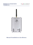
1
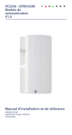
IP100-EI08
Internet Module (IP100)
Figure 2: IP100 Connection
IP100 Connections
IP100 Plastic Box
G
Setting up IP Reporting
H
1.
A
Instructions
Version 1.5
2.
B
3.
H
PARADOX.COM
Printed in Canada 06/2009
I
Introduction
C
D
The IP100 is an IP-based Web solution that provides the ability to report system events to
monitoring station over an IP network as well as an Internet communication link to control and
monitor a security system.
E
IP Line Monitoring Options
[5]
Partial view of the
metal box
J
@
Disabled
When disarmed: Trouble only
When armed: Trouble only
OFF
When disarmed: Trouble only
When armed: Audible alarm
ON
Silent alarm becomes audible alarm
OFF
Use dialer reporting
N As backup for IP/
(telephone)
GPRS reporting
IP/GPRS reporting
N Disabled
OFF
OFF
ON
ON
LED
Email Notification
E
On until both the control panel and network are detected - On
when DHCP server is not responding - On during a reset
Flashes during firmware upgrade
RX:
Flashes when receiving data from the panel
TX:
Flashes when sending data to the panel
POLLING: On when connected with paradoxmyhome.com
STATUS:
On when a user is connected
LINK:
On when connected to a network
LAN:
Flashes when transferring data through the LAN
To reset the module to its default settings, press and hold the RESET button
for 5 seconds, release it, and then press it again while the Error LED is
flashing. The Error LED will remain lit during the reset.
Connect to the router (CAT-5 Ethernet cable)
Connect to the SERIAL connector of the panel (4-pin serial cable)
Connect to a 307USB and use WinLoad to update the firmware (punch out a
hole when using the plastic enclosure)
Mounting
G
H
I
J
Use a screw with this hole to mount the IP100 in the metal box
Retractable flat-mount brackets (for optional wall mounting)
Mount the IP100 on the top right corner of the metal box
Mounting screw
A
WAN
IP100
Router
IPR512
IP Receiver
B
Web Access
Installation Requirements
To install and configure the IP100, the following hardware/software will be needed:
• Ethernet-compatible computer with internet access (for Remote Access only, see reverse)
• Router
• 4-pin serial cable (included)
• CAT-5 Ethernet cable: max 90m (295 ft.) (not included)
• Paradox IP Exploring Tools software (for Remote Access only, see reverse) - found at
paradox.com > GSM/IP/Voice > IP100
Overview
Connecting the Hardware
IP Reporting
Remote Access
Step 1: Setting up the Router
Step 2: Configuring the IP100
Step 3: Setting up ParadoxMyHome (optional)
Step 4: Using a Web Browser to Access the System
Firmware and Language Update
Connecting the Hardware
The module must be connected to the control panel and a network. The IP100’s error LED will
light up until both the control panel and network are detected.
1. Connect the 4-pin serial cable between the panel’s serial connector and the IP100’s serial
connector, shown as D in Figure 2.
2. Connect the Ethernet cable between the router and the IP100’s network connector,
shown as C in Figure 2. The router must be installed in the same room as the receiver.
3. The onboard LEDs will illuminate to indicate the IP100’s status.
ON
ERROR:
Monitoring
Station
Router
Home PC
[6]
OFF
Figure 1: Overview
Control Panel
Ensure that the panel’s report code format is set to either Ademco Contact ID (default) or
SIA:
MG/SP/E: section [810]
EVO: section [3070]
Enter the IP reporting account numbers (one for each partition):
MG/SP/E: section [918] / [919]
EVO: section [2976] to [2983]
In the General IP Options section, set up IP line monitoring options and dialer options,
and ensure IP reporting is enabled:
MG/SP/E: section [806]
C
D
[7]
[8]
reporting
N Enabled
EVO: section [2975]
IP Line Monitoring Options
[5]
[6]
Disabled
When disarmed: Trouble only
When armed: Audible alarm
OFF
When disarmed: Trouble only (default)
When armed: Trouble only
ON
Silent alarm becomes audible alarm
OFF
ON
Use dialer reporting
N As backup for IP/
N In addition to IP
(telephone)
GPRS reporting
reporting
IP/GPRS reporting
N Disabled
N Enabled
OFF
OFF
OFF
ON
ON
ON
[7]
[8]
4.
IP Reporting
Enter the monitoring station’s IP address(es), IP port(s), receiver password(s), and
security profile(s) (information must be obtained from the monitoring station).
MG/SP/E Sections
Control panels with an IP100 can report system events to a monitoring station over an IP
network. To use IP reporting, the monitoring station must employ the Paradox IP Receiver
(IPR512). When using IP reporting, the IP module has the ability to poll the monitoring station.
This supervision feature greatly increases the site’s security.
In order for the IP100 to report to the monitoring station via IP connection, the IP100 must first
be registered to the monitoring station’s IP Receiver (IPR512). Telephone reporting can be
used in conjunction with, or as a backup to IP reporting.
Before registering the IP100, the following information must be obtained from the monitoring
station:
• Account number(s) - One account number for each partition used. IP/GPRS reporting uses a
different set of account numbers than those used fro dialer reporting. The specific section
numbers for the IP/GPRS Account Numbers are listed in this document.
• IP address(es)(12-digit number e.g. for 195.4.8.250 you must enter 195.004.008.250)
The IP address(es) indicates which of the monitoring station’s IP Receivers will be used for
IP reporting.
• IP port(s) (5-digit number. For 4-digit numbers, enter 0 before the first digit.)
The IP port refers to the port used by the monitoring station’s IP Receiver.
• Receiver password(s) (up to 32-digits)
The receiver password is used to encrypt the IP100 registration process.
• Security profile(s) (2-digit number)
The security profile indicates how frequently the monitoring station is polled by the IP100.
Security profile numbers and polling frequency are defined by the monitoring station.
ON
N In addition to IP
IP Receiver
IP Address1
IP Port1
IP Address2
IP Port2
IP Password
IP Profile
5.
#1
[929]
[930]
[931]
[932]
[933]
[934]
#2
[936]
[937]
[938]
[939]
[940]
[941]
EVO Sections
Backup
[943]
[944]
[945]
[946]
[947]
[948]
IP Receiver
#1
IP Address1 [2984]
IP Port1
IP Address2
IP Port2
IP Password
IP Profile
#2
[2986]
#3
#4
[2988] [2990]
Register the IP100 module with the monitoring station. To register, enter the sections
below and press [ARM]. The registration status is displayed as well as any registration
errors.
MG/SP/E Registration
IP Receiver #
#1 #2 Backup
Register/Status [935] [942] [949]
EVO Registration
IP Receiver #
Register/Status
#1
#2
#3
#4
[2985] [2987] [2989] [2991]
NOTE: An IP100 used with an MG/SP/E system will always poll using the partition 1 IP
account number. When using an EVO system, the partition 1 IP account is used by default, but
can be defined in section [3020]. All reported system events will originate from the partition
selected in this section.
Remote Access
5.
The IP100 is an IP-based Web solution that provides an Internet communication link to control
and monitor a security system with Web browsers or NEware. This provides the user with the
freedom to access the system from anywhere in the world.
Step 1: Setting up the Router
This step allows you to set up the router so that the IP100 module can function properly.
1.
2.
3.
Ensure that the router is connected properly
as indicated in the router’s instructions.
Access your router’s configuration page.
Refer to your router’s manual for the exact
procedure. In most cases, this is done by
entering the router’s static IP address in the
address bar of your Web browser, see Figure
3. For this manual, we will use 192.168.1.1 as
an example, since it is a commonly used
default router IP address. Your router’s IP
address may be indicated in the router’s
instructions or on a sticker on the router.
In the router’s configuration page, check the
DHCP settings.
If DHCP is enabled, verify that the IP
address range leaves at least one IP address
available outside of the range. The range
shown in Figure 4, would leave addresses 2
to 4 and 101 to 254 available (all the numbers
in an IP address are between 1 and 254.)
Record one of the addresses outside the
DHCP range as the one you will use for the
IP100.
Figure 3: Router Configuration Page*
In the router’s configuration page, go to the
Port Range Forwarding section (also known
as “port mapping” or “port redirection.”) Add a
service/item, set the Port to 80 and enter the
static IP address selected in the previous
step for the IP module (see Figure 4.) If port
80 is already used, you can use another one,
such as 81 or 82 but you will have to modify
the IP100’s settings in step 2. Some Internet
Service Providers block port 80, therefore the
IP100 may function locally using port 80 but
not over the Internet. If this is the case,
change the port to another number. Repeat
this step for port 10 000.
Step 2: Configuring the IP100
1.
2.
3.
4.
Using a computer connected to the same
network as the IP100, open the Paradox IP
Exploring Tools.
Click Find It. Your IP100 appears in the list.
Right-click your IP100 and select Module
setup, see Figure 6.
Enter the static IP address you recorded in
Step 1.3 or modify the address so that it
corresponds to the one you have selected for
the IP100. Enter the IP100’s password (default:
paradox) and click OK. If it indicates that the IP
address is already used, change it to another
and modify it in the Port Forwarding of the
router (step 1.4) and go back to step 2.1.
Figure 7: IP Address Assignment
Step 3: Setting up ParadoxMyHome
(optional)
* Screenshot may differ depending
on type of router used
Figure 4: DHCP Settings*
* Screenshot may differ depending
on type of router used
If DHCP is disabled, the IP100 will use the
default address of 192.168.1.250. It is
possible to change that address if needed
using the Paradox IP Exploring Tools
software.
4.
Set any additional information such as port, subnet
mask, etc. To find this information, click Start >
Programs > Accessories > Command Prompt.
Enter command: IPCONFIG /ALL (with space after
IPCONFIG).
NOTE: For increased communication security, please
change the default PC password and Panel ID in the
control panel.
NOTE: The IP100 supports SMTP and ESMTP
protocols (TLS/SSL not supported).
Figure 5: Port Forwarding*
* Screenshot may differ depending
on type of router used
Figure 6: IP100 Configuration Access
This step is not needed if the IP address provided
by the Internet Service Provider is static.
Using the ParadoxMyHome service will allow you to
access your system over the Internet with a dynamic IP
address. The IP100 will then poll the ParadoxMyHome
server to keep the information updated. By default, the
ParadoxMyHome service is disabled.
To set up the ParadoxMyHome service:
Figure 8: Module Registration
1. Go to www.paradoxmyhome.com, click Request
Login and provide the requested information.
2. Start the Paradox IP Exploring Tools software and
right-click the IP100.
3. Select Register to ParadoxMyHome.
4. Enter the requested information. Enter a unique
SiteID for the module.
5. When registration is complete, you can access the
IP100 page by going to:
www.paradoxmyhome.com/[SiteID]
If there are issues with connecting to the IP100, try
making the polling delay shorter (configured on the
IP100’s webpage interface), so that the IP information available for the ParadoxMyHome
connection is up to date. However, a shorter delay for the polls will increase the traffic on the
internet (WAN).
Step 4: Using a Web Browser to Access the System
Once the module is configured, it can be accessed either from the local network or through the
internet using the user code or user IP100 password.
On-Site Access:
1. Enter the IP address assigned to the IP100 in the address bar of your Web browser. If you
have used a port other than port 80, you must add [: port number] at the end. (For
example, if the port used is 81, the IP address entered should look like this: http://
192.168.1.250:81).
or
Use the Paradox IP Exploring Tools software, click Refresh and double-click on your
IP100 in the list.
2. Enter your alarm system’s User Code and IP100 password (default: paradox).
Off-Site Access:
1. Go to www.paradoxmyhome.com/siteID (replace ‘siteID’ by the ‘siteID’ you used to
register with the ParadoxMyHome service)
2. Enter your alarm system’s User Code and IP100 password (default: paradox).
Firmware and
Language Update
Figure 9: Firmware and Language Update
To update an IP100 using IP Exploring:
1. Open IP Exploring Tools.
2. Click the Language / Update tab (see
Figure 9).
3. Select your preferred language in the
Language drop-down list.
4. Select the correct Connection Mode from
the following three types:
Locally - Select your IP100 from the Site
Name list
Remotely - Enter your module's IP
Address (as shown in the Exploring Mode
tab) and NEware Port (default =
10000). Click the Exploring Mode tab,
right-click the IP100 and select More
Details.
ParadoxMyHome - Enter your IP module
site ID.
5. Enter the module password.
6. Click Update Module. A Web update
progress box appears (see Figure 10).
If a new firmware version is found, you are
informed of the old version number and you
will have to confirm the installation of the new
version. The update process begins. If it is
interrupted, the IP100 will not be functional
until the firmware is properly installed.
Figure 10: Web update progress
Glossary
IP Reporting
Using IP reporting, system events are transmitted
to the monitoring station via the Internet. This
method provides increased security due to frequent polling by the monitoring station.
IP Addresses (Static/Fixed or Dynamic)
(Internet Protocol address) The address of a device connected to an IP network. This is
equivalent to a phone number in the sense that they are all unique and are used to establish
communication to a particular network. In an IP network, addresses can either be fixed or
dynamic. Fixed addresses are established by the network administrator while dynamic
addresses are decided through DHCP protocols and change over time.
DHCP
(Dynamic Host Configuration Protocol) This protocol automatically assigns temporary IP
addresses to devices connected to an IP network. It eliminates the need to set static IP
addresses every time a device is added to a network. This is done automatically in servers
and routers.
Port Forwarding
Port Forwarding allows a router in a private network to let a party outside the network to
connect a device in the network. Once port forwarding is set, requests from the internet
(outside users) will be forwarded to the proper device. If you were to set the port number 80
(HTTP) to be forwarded to IP address 192.168.1.101, then all HTTP requests from outside
users to this port would be forwarded to the device with that address.
Table 1: Technical Specifications
Panel Compatibility
Browser Requirements
Encryption
Current Consumption
Input Voltage
Enclosure Dimensions
Any Digiplex EVO panel (V2.02 for IP reporting)
Any Spectra SP series panel (V3.42 for IP reporting)
Any MG5000 / MG5050 panel (V4.0 for IP reporting)
Any Esprit E55 (does not support IP reporting)
Esprit E65 V2.10 or higher
Optimized for Internet Explorer 6 or higher and Mozilla 1.5 or
higher 1024 x 768 resolution minimum
AES 256-bit, MD5 and RC4
110 mA
Powered by the serial port
9.9cm x 7.2cm x 1.8cm (3.9in x 2.8in x 0.7in)
Warranty
For complete warranty information on this product please refer to the Limited Warranty Statement found on the Website www.paradox.com/
terms. Your use of the Paradox product signifies your acceptance of all warranty terms and conditions. EVO, Digiplex EVO, Magellan,
Spectra SP, Esprit and Esprit E55 are trademarks or registered trademarks of Paradox Security Systems Ltd. or its affiliates in Canada, the
United States and/or other countries. For the latest information on products approvals, such as UL and CE, please visit www.paradox.com.
© 2009 Paradox Security Systems Ltd. All rights reserved. Specifications may change without prior notice. One or more of the following US
patents may apply: 7046142, 6215399, 6111256, 6104319, 5920259, 5886632, 5721542, 5287111, 5119069, 5077549 and RE39406 and
other pending patents may apply. Canadian and international patents may also apply.
This product includes software developed by Viola Systems (http://www.violasystems.com/) Copyright © 2002-2002 Viola Systems
Ltd. All rights reserved.