1
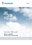
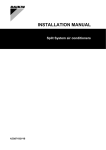
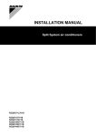
INSTALLATION MANUAL Split System air conditioners RZQS71C7V1B RZQS100C7V1B RZQS125C7V1B RZQS140C7V1B 1 B2 D2 E C L1 H B1 L2 A 1 D1 B2 D2 E C L1 1 H B1 L2 A D1 2 1 3 2 6 5 4 E L4 H1 2 L4 L1 L3 C L7 H L1 H2 H2 L3 H1 L1 H1 L1 L6 H1 L3 L2 A L5 H2 L2 L2 B D 3 4 5 7 6 9 A 3 B 1~ 50 Hz 220-240 V 1 2 1 2 4 5 7 8 6 1 3 3 R410A 2 4 5 6 1 3 8 R410A 7 2 8 4 5 9 9 IV CE - DECLARACION-DE-CONFORMIDAD CE - DICHIARAZIONE-DI-CONFORMITA CE - ¢H§ø™H ™YMMOPºø™H™ 05 Nota * 04 Bemerk * 03 Remarque * 02 Hinweis * 01 Note * 19 ob upoštevanju določb: 20 vastavalt nõuetele: 21 следвайки клаузите на: 22 laikantis nuostatų, pateikiamų: 23 ievērojot prasības, kas noteiktas: 24 održiavajúc ustanovenia: 25 bunun koşullarına uygun olarak: delineato nel <A> e giudicato positivamente da <B> secondo il Certificato <C>. fiˆ˜ ηıÔÚ›˙ÂÙ·È ÛÙÔ <A> Î·È ÎÚ›ÓÂÙ·È ıÂÙÈο ·fi ÙÔ <B> Û‡Ìʈӷ Ì ÙÔ ¶ÈÛÙÔÔÈËÙÈÎfi <C>. 08 Nota * tal como estabelecido em <A> e com o parecer positivo de <B> de acordo com o Certificado <C>. 09 Примечание * как указано в <A> и в соответствии с положительным решением <B> согласно Свидетельству <C>. 10 Bemærk * som anført i <A> og positivt vurderet af <B> i henhold til Certifikat <C>. 07 ™ËÌ›ˆÛË * 06 Nota * 10 under iagttagelse af bestemmelserne i: 11 enligt villkoren i: 12 gitt i henhold til bestemmelsene i: 13 noudattaen määräyksiä: 14 za dodržení ustanovení předpisu: 15 prema odredbama: 16 követi a(z): 17 zgodnie z postanowieniami Dyrektyw: 18 în urma prevederilor: as set out in <A> and judged positively by <B> according to the Certificate <C>. wie in der <A> aufgeführt und von <B> positiv beurteilt gemäß Zertifikat <C>. tel que défini dans <A> et évalué positivement par <B> conformément au Certificat <C>. zoals vermeld in <A> en positief beoordeeld door <B> overeenkomstig Certificaat <C>. como se establece en <A> y es valorado positivamente por <B> de acuerdo con el Certificado <C>. 01 following the provisions of: 02 gemäß den Vorschriften der: 03 conformément aux stipulations des: 04 overeenkomstig de bepalingen van: 05 siguiendo las disposiciones de: 06 secondo le prescrizioni per: 07 Ì ًÚËÛË Ùˆv ‰È·Ù¿Íˆv Ùˆv: 08 de acordo com o previsto em: 09 в соответствии с положениями: EN60335-2-40, 01 are in conformity with the following standard(s) or other normative document(s), provided that these are used in accordance with our instructions: 02 der/den folgenden Norm(en) oder einem anderen Normdokument oder -dokumenten entspricht/entsprechen, unter der Voraussetzung, daß sie gemäß unseren Anweisungen eingesetzt werden: 03 sont conformes à la/aux norme(s) ou autre(s) document(s) normatif(s), pour autant qu'ils soient utilisés conformément à nos instructions: 04 conform de volgende norm(en) of één of meer andere bindende documenten zijn, op voorwaarde dat ze worden gebruikt overeenkomstig onze instructies: 05 están en conformidad con la(s) siguiente(s) norma(s) u otro(s) documento(s) normativo(s), siempre que sean utilizados de acuerdo con nuestras instrucciones: 06 sono conformi al(i) seguente(i) standard(s) o altro(i) documento(i) a carattere normativo, a patto che vengano usati in conformità alle nostre istruzioni: 07 Â›Ó·È Û‡Ìʈӷ Ì ÙÔ(·) ·ÎfiÏÔ˘ıÔ(·) ÚfiÙ˘Ô(·) ‹ ¿ÏÏÔ ¤ÁÁÚ·ÊÔ(·) ηÓÔÓÈÛÌÒÓ, ˘fi ÙËÓ ÚÔ¸fiıÂÛË fiÙÈ ¯ÚËÛÈÌÔÔÈÔ‡ÓÙ·È Û‡Ìʈӷ Ì ÙȘ Ô‰ËÁ›Â˜ Ì·˜: * = , , 1, 2, 3, ..., 9 RZQS71C7V1B*, RZQS100C7V1B*, RZQS125C7V1B*, RZQS140C7V1B*, CE - ERKLÆRING OM-SAMSVAR CE - ILMOITUS-YHDENMUKAISUUDESTA CE - PROHLÁŠENÍ-O-SHODĚ Jiro Tomita Director Quality Assurance Ostend, 3rd of December 2007 11 Information * enligt <A> och godkänts av <B> enligt Certifikatet <C>. 12 Merk * som det fremkommer i <A> og gjennom positiv bedømmelse av <B> ifølge Sertifikat <C>. 13 Huom * jotka on esitetty asiakirjassa <A> ja jotka <B> on hyväksynyt Sertifikaatin <C> mukaisesti. 14 Poznámka * jak bylo uvedeno v <A> a pozitivně zjištěno <B> v souladu s osvědčením <C>. 15 Napomena * kako je izloženo u <A> i pozitivno ocijenjeno od strane <B> prema Certifikatu <C>. 16 Megjegyzés * a(z) <A> alapján, a(z) <B> igazolta a megfelelést, a(z) <C> tanúsítvány szerint. 17 Uwaga * zgodnie z dokumentacją <A>, pozytywną opinią <B> i Świadectwem <C>. 18 Notă * aşa cum este stabilit în <A> şi apreciat pozitiv de <B> în conformitate cu Certificatul <C>. 19 Opomba * kot je določeno v <A> in odobreno s strani <B> v skladu s certifikatom <C>. 20 Märkus * nagu on näidatud dokumendis <A> ja heaks kiidetud <B> järgi vastavalt sertifikaadile <C>. Low Voltage 2006/95/EC Machinery 98/37/EC Electromagnetic Compatibility 2004/108/EC * CE - ATITIKTIES-DEKLARACIJA CE - ATBILSTĪBAS-DEKLARĀCIJA CE - VYHLÁSENIE-ZHODY CE - UYUMLULUK-BİLDİRİSİ 21 Забележка * както е изложено в <A> и оценено положително от <B> съгласно Cертификата <C>. 22 Pastaba * kaip nustatyta <A> ir kaip teigiamai nuspręsta <B> pagal Sertifikatą <C>. 23 Piezīmes * kā norādīts <A> un atbilstoši <B> pozitīvajam vērtējumam saskaņā ar sertifikātu <C>. 24 Poznámka * ako bolo uvedené v <A> a pozitívne zistené <B> v súlade s osvedčením <C>. 25 Not * <A>‘da belirtildiği gibi ve <C> Sertifikasına göre <B> tarafından olumlu olarak değerlendirildiği gibi. DAIKIN.TCF.021E3/10-2007 KEMA 2024351-QUA/EMC02-4565 <B> <C> 19 Direktive z vsemi spremembami. 20 Direktiivid koos muudatustega. 21 Директиви, с техните изменения. 22 Direktyvose su papildymais. 23 Direktīvās un to papildinājumos. 24 Smernice, v platnom znení. 25 Değiştirilmiş halleriyle Yönetmelikler. <A> 10 Direktiver, med senere ændringer. 11 Direktiv, med företagna ändringar. 12 Direktiver, med foretatte endringer. 13 Direktiivejä, sellaisina kuin ne ovat muutettuina. 14 v platném znění. 15 Smjernice, kako je izmijenjeno. 16 irányelv(ek) és módosításaik rendelkezéseit. 17 z późniejszymi poprawkami. 18 Directivelor, cu amendamentele respective. 16 megfelelnek az alábbi szabvány(ok)nak vagy egyéb irányadó dokumentum(ok)nak, ha azokat előírás szerint használják: 17 spełniają wymogi następujących norm i innych dokumentów normalizacyjnych, pod warunkiem że używane są zgodnie z naszymi instrukcjami: 18 sunt în conformitate cu următorul (următoarele) standard(e) sau alt(e) document(e) normativ(e), cu condiţia ca acestea să fie utilizate în conformitate cu instrucţiunile noastre: 19 skladni z naslednjimi standardi in drugimi normativi, pod pogojem, da se uporabljajo v skladu z našimi navodili: 20 on vastavuses järgmis(t)e standardi(te)ga või teiste normatiivsete dokumentidega, kui neid kasutatakse vastavalt meie juhenditele: 21 съответстват на следните стандарти или други нормативни документи, при условие, че се използват съгласно нашите инструкции: 22 atitinka žemiau nurodytus standartus ir (arba) kitus norminius dokumentus su sąlyga, kad yra naudojami pagal mūsų nurodymus: 23 tad, ja lietoti atbilstoši ražotāja norādījumiem, atbilst sekojošiem standartiem un citiem normatīviem dokumentiem: 24 sú v zhode s nasledovnou(ými) normou(ami) alebo iným(i) normatívnym(i) dokumentom(ami), za predpokladu, že sa používajú v súlade s našim návodom: 25 ürünün, talimatlarımıza göre kullanılması koşuluyla aşağıdaki standartlar ve norm belirten belgelerle uyumludur: 01 Directives, as amended. 02 Direktiven, gemäß Änderung. 03 Directives, telles que modifiées. 04 Richtlijnen, zoals geamendeerd. 05 Directivas, según lo enmendado. 06 Direttive, come da modifica. 07 √‰ËÁÈÒv, fiˆ˜ ¤¯Ô˘Ó ÙÚÔÔÔÈËı›. 08 Directivas, conforme alteração em. 09 Директив со всеми поправками. 08 estão em conformidade com a(s) seguinte(s) norma(s) ou outro(s) documento(s) normativo(s), desde que estes sejam utilizados de acordo com as nossas instruções: 09 соответствуют следующим стандартам или другим нормативным документам, при условии их использования согласно нашим инструкциям: 10 overholder følgende standard(er) eller andet/andre retningsgivende dokument(er), forudsat at disse anvendes i henhold til vore instrukser: 11 respektive utrustning är utförd i överensstämmelse med och följer följande standard(er) eller andra normgivande dokument, under förutsättning att användning sker i överensstämmelse med våra instruktioner: 12 respektive utstyr er i overensstemmelse med følgende standard(er) eller andre normgivende dokument(er), under forutssetning av at disse brukes i henhold til våre instrukser: 13 vastaavat seuraavien standardien ja muiden ohjeellisten dokumenttien vaatimuksia edellyttäen, että niitä käytetään ohjeidemme mukaisesti: 14 za předpokladu, že jsou využívány v souladu s našimi pokyny, odpovídají následujícím normám nebo normativním dokumentům: 15 u skladu sa slijedećim standardom(ima) ili drugim normativnim dokumentom(ima), uz uvjet da se oni koriste u skladu s našim uputama: CE - IZJAVA O SKLADNOSTI CE - VASTAVUSDEKLARATSIOON CE - ДЕКЛАРАЦИЯ-ЗА-СЪОТВЕТСТВИЕ 19 o z vso odgovornostjo izjavlja, da so modeli klimatskih naprav, na katere se izjava nanaša: 20 x kinnitab oma täielikul vastutusel, et käesoleva deklaratsiooni alla kuuluvad kliimaseadmete mudelid: 21 b декларира на своя отговорност, че моделите климатична инсталация, за които се отнася тази декларация: 22 t visiška savo atsakomybe skelbia, kad oro kondicionavimo prietaisų modeliai, kuriems yra taikoma ši deklaracija: 23 v ar pilnu atbildību apliecina, ka tālāk uzskaitīto modeĮu gaisa kondicionētāji, uz kuriem attiecas šī deklarācija: 24 k vyhlasuje na vlastnú zodpovednosť, že tieto klimatizačné modely, na ktoré sa vzťahuje toto vyhlásenie: 25 w tamamen kendi sorumluluğunda olmak üzere bu bildirinin ilgili olduğu klima modellerinin aşağıdaki gibi olduğunu beyan eder: CE - IZJAVA-O-USKLAĐENOSTI CE - MEGFELELŐSÉGI-NYILATKOZAT CE - DEKLARACJA-ZGODNOŚCI CE - DECLARAŢIE-DE-CONFORMITATE 10 q erklærer under eneansvar, at klimaanlægmodellerne, som denne deklaration vedrører: 11 s deklarerar i egenskap av huvudansvarig, att luftkonditioneringsmodellerna som berörs av denna deklaration innebär att: 12 n erklærer et fullstendig ansvar for at de luftkondisjoneringsmodeller som berøres av denne deklarasjon innebærer at: 13 j ilmoittaa yksinomaan omalla vastuullaan, että tämän ilmoituksen tarkoittamat ilmastointilaitteiden mallit: 14 c prohlašuje ve své plné odpovědnosti, že modely klimatizace, k nimž se toto prohlášení vztahuje: 15 y izjavljuje pod isključivo vlastitom odgovornošću da su modeli klima uređaja na koje se ova izjava odnosi: 16 h teljes felelőssége tudatában kijelenti, hogy a klímaberendezés modellek, melyekre e nyilatkozat vonatkozik: 17 m deklaruje na własną i wyłączną odpowiedzialność, że modele klimatyzatorów, których dotyczy niniejsza deklaracja: 18 r declară pe proprie răspundere că aparatele de aer condiţionat la care se referă această declaraţie: CE - DECLARAÇÃO-DE-CONFORMIDADE СЕ - ЗАЯВЛЕНИЕ-О-СООТВЕТСТВИИ CE - OPFYLDELSESERKLÆRING CE - FÖRSÄKRAN-OM-ÖVERENSTÄMMELSE 01 a declares under its sole responsibility that the air conditioning models to which this declaration relates: 02 d erklärt auf seine alleinige Verantwortung daß die Modelle der Klimageräte für die diese Erklärung bestimmt ist: 03 f déclare sous sa seule responsabilité que les appareils d'air conditionné visés par la présente déclaration: 04 l verklaart hierbij op eigen exclusieve verantwoordelijkheid dat de airconditioning units waarop deze verklaring betrekking heeft: 05 e declara baja su única responsabilidad que los modelos de aire acondicionado a los cuales hace referencia la declaración: 06 i dichiara sotto sua responsabilità che i condizionatori modello a cui è riferita questa dichiarazione: 07 g ‰ËÏÒÓÂÈ Ì ·ÔÎÏÂÈÛÙÈ΋ Ù˘ ¢ı‡ÓË fiÙÈ Ù· ÌÔÓ٤Ϸ ÙˆÓ ÎÏÈÌ·ÙÈÛÙÈÎÒÓ Û˘Û΢ÒÓ ÛÙ· ÔÔ›· ·Ó·Ê¤ÚÂÙ·È Ë ·ÚÔ‡Û· ‰‹ÏˆÛË: 08 p declara sob sua exclusiva responsabilidade que os modelos de ar condicionado a que esta declaração se refere: 09 u заявляет, исключительно под свою ответственность, что модели кондиционеров воздуха, к которым относится настоящее заявление: Daikin Europe N.V. CE - DECLARATION-OF-CONFORMITY CE - KONFORMITÄTSERKLÄRUNG CE - DECLARATION-DE-CONFORMITE CE - CONFORMITEITSVERKLARING 3PW34877-3B RZQS71C7V1B RZQS100C7V1B RZQS125C7V1B RZQS140C7V1B CONTENTS Page WARNING Safety considerations ........................................................................ 1 ■ Perform installation work in accordance with this installation manual. Improper installation may lead to water leakage, electric shocks or fire. ■ Consult your local dealer regarding what to do in case of refrigerant leakage. When the air conditioner is to be installed in a small room, it is necessary to take proper measures so that the amount of any leaked refrigerant does not exceed the concentration limit in the event of a leakage. Otherwise, this may lead to an accident due to oxygen depletion. ■ Be sure to use only the specified accessories and parts for installation work. Failure to use the specified parts may result in water leakage, electric shocks, fire, or the unit falling. ■ Install the air conditioner on a foundation that can withstand its weight. Insufficient strength may result in the fall of equipment and causing injury. ■ Carry out the specified installation work in consideration of strong winds, typhoons, or earthquakes. Improper installation work may result in accidents due to fall of equipment. ■ Make certain that all electrical work is carried out by qualified personnel according to the local laws and regulations and this installation manual, using a separate circuit. Insufficient capacity of the power supply circuit or improper electrical construction may lead to electric shocks or fire. ■ Make sure that all wiring is secure, using the specified wires and ensuring that external forces do not act on the terminal connections or wires. Incomplete connection or fixing may cause a fire. ■ When wiring between the indoor and outdoor units, and wiring the power supply, form the wires so that the frontside panel can be securely fastened. If the frontside panel is not in place, overheat of the terminals, electric shocks or a fire may be caused. ■ If refrigerant gas leaks during installation work, ventilate the area immediately. Toxic gas may be produced if refrigerant gas comes into contact with fire. ■ After completing the installation work, check to make sure that there is no leakage of refrigerant gas. Toxic gas may be produced if refrigerant gas leaks into the room and comes into contact with a source of fire, such as a fan heater, stove or cooker. ■ Before touching electric terminal parts, turn off power switch. Before installation.............................................................................. 2 Selecting installation site................................................................... 3 Precautions on installation ................................................................ 4 Installation servicing space ............................................................... 4 Refrigerant pipe size and allowable pipe length................................ 5 Precautions on refrigerant piping ...................................................... 6 Refrigerant piping.............................................................................. 6 Evacuating......................................................................................... 8 Charging refrigerant .......................................................................... 9 Electrical wiring work....................................................................... 11 Test operation.................................................................................. 12 Disposal requirements .................................................................... 13 Wiring diagram ................................................................................ 14 READ THESE INSTRUCTIONS CAREFULLY BEFORE INSTALLATION. KEEP THIS MANUAL IN A HANDY PLACE FOR FUTURE REFERENCE. IMPROPER INSTALLATION OR ATTACHMENT OF EQUIPMENT OR ACCESSORIES COULD RESULT IN ELECTRIC SHOCK, SHORT-CIRCUIT, LEAKS, FIRE OR OTHER DAMAGE TO THE EQUIPMENT. BE SURE ONLY TO USE ACCESSORIES MADE BY DAIKIN WHICH ARE SPECIFICALLY DESIGNED FOR USE WITH THE EQUIPMENT AND HAVE THEM INSTALLED BY A PROFESSIONAL. IF UNSURE OF INSTALLATION PROCEDURES OR USE, ALWAYS CONTACT YOUR DAIKIN DEALER FOR ADVICE AND INFORMATION. SAFETY CONSIDERATIONS The precautions listed here are divided into the following two types. Both cover very important topics, so be sure to follow them carefully. WARNING CAUTION If the warning is not observed, it may cause serious casualties. If the caution is not observed, it may cause injury or damage to the equipment. WARNING ■ For use of air-conditioning units in applications with temperature alarm settings it is advised to foresee a delay of 10 minutes for signalling the alarm in case the alarm temperature is exceeded. The airconditioning unit may stop for several minutes during normal operation for "defrosting of the indoor unit" or when in "thermostat-stop" operation. ■ Ask your dealer or qualified personnel to carry out installation work. Do not install the machine by yourself. Improper installation may result in water leakage, electric shocks or fire. Installation manual 1 Installation manual Split System air conditioners RZQS71~140C7V1B Split System air conditioners 4PW40416-1 WARNING CAUTION ■ Live parts can be easily touched by accident. Never leave the unit unattended during installation or servicing when the service panel is removed. ■ ■ When planning to relocate former installed units, you must first recover the refrigerant after the pumpingdown operation. Refer to chapter "Precaution for pumping-down operation" on page 10. ■ Never directly touch any accidental leaking refrigerant. This could result in severe wounds caused by frostbite. Do not install the air conditioner in places such as the following: ■ Where there is mist of mineral oil, oil spray or vapour for example a kitchen. Plastic parts may deteriorate, and cause them to fall out or water to leak. ■ Where corrosive gas, such as sulphurous acid gas, is produced. Corrosion of copper pipes or soldered parts may cause the refrigerant to leak. ■ Where there is machinery which emits electromagnetic waves. Electromagnetic waves may disturb the control system, and cause malfunction of the equipment. CAUTION ■ Ground the air conditioner. Grounding resistance should be according to national regulations Do not connect the earth wire to gas or water pipes, lightning conductor or telephone earth wire. Incomplete grounding may cause electric shocks. ■ Where flammable gases may leak, where carbon fiber or ignitable dust is suspended in the air or where volatile flammables, such as thinner or gasoline, are handled. Such gases may cause a fire. ■ Where the air contains high levels of salt such as that near the ocean. ■ Gas pipe. Ignition or explosion may occur if the gas leaks. ■ Where voltage fluctuates a lot, such as that in factories. ■ Water pipe. Hard vinyl tubes are not effective grounds. ■ In vehicles or vessels. ■ Lightning conductor or telephone ground wire. Electric potential may rise abnormally if struck by lightning. ■ Be sure to install an earth leakage breaker. Failure to install an earth leakage breaker may cause electric shocks and fire. ■ Install drain piping according to this installation manual to ensure good drainage, and insulate the pipe to prevent condensation. Improper drain piping may cause water leakage, and make the furnitures get wet. ■ Install the indoor and outdoor units, power wire and connecting wire at least 1 meter away from televisions or radios to prevent image interference or noise. (Depending on the radio waves, a distance of 1 meter may not be sufficient to eliminate the noise.) ■ Do not rinse the outdoor unit. This may cause electric shocks or fire. ■ Where acidic or alkaline vapour is present. BEFORE INSTALLATION Since maximum working pressure is 4.0 MPa or 40 bar, pipes of larger wall thickness may be required. Refer to paragraph "Selection of piping material" on page 5. Precautions for R410A ■ The refrigerant requires strict cautions for keeping the system clean, dry and tight. - Clean and dry Foreign materials (including mineral oils or moisture) should be prevented from getting mixed into the system. - Tight Read "Precautions on refrigerant piping" on page 6 carefully and follow these procedures correctly. ■ Since R410A is a mixed refrigerant, the required additional refrigerant must be charged in its liquid state. (If the refrigerant is in state of gas, its composition changes and the system will not work properly). ■ The connected indoor units must be indoor units designed exclusively for R410A. Installation ■ ■ ■ ■ ■ ■ RZQS71~140C7V1B Split System air conditioners 4PW40416-1 For installation of the indoor unit(s), refer to the indoor unit installation manual. Illustrations show class 125 outdoor unit type. Other types also follow this installation manual. This outdoor unit requires the pipe branching kit (optional) when used as the outdoor unit for the simultaneous operation system. Refer to catalogues for details. Never operate the unit with a damaged or disconnected discharge thermistor and suction thermistor, burning of the compressor may result. Be sure to confirm the model name and the serial no. of the outer (front) plates when attaching/detaching the plates to avoid mistakes. When closing the service panels, take care that the tightening torque does not exceed 4.1 N•m. Installation manual 2 Accessories 2 Check if the following accessories are included with the unit Installation manual 1 Clamp 2 Strong winds of 5 m/sec or more blowing against the outdoor unit's air outlet causes short circuit (suction of discharge air), and this may have the following consequences: - Deterioration of the operational capacity. - Frequent frost acceleration in heating operation. - Disruption of operation due to rise of high pressure. - When a strong wind blows continuously on the face of the unit, the fan can start rotating very fast until it breaks. Refer to the figures for installation of this unit in a place where the wind direction can be foreseen. See the figure below for the location of the accessories. ■ 1 When installing the unit in a place exposed to strong wind, pay special attention to the following. Accessories Turn the air outlet side toward the building's wall, fence or screen. 1 Handling Make sure there is enough room to do the installation As shown in the figure, bring the unit slowly by grabbing the left and right grips. ■ Set the outlet side at a right angle to the direction of the wind. Strong wind Place your hands on the corner instead of holding the suction inlet in the side of the casing, otherwise the casing could be deformed. Blown air Take care not to let hands or objects come in contact with rear fins. SELECTING 1 Make sure to provide for adequate measures in order to prevent that the outdoor unit be used as a shelter by small animals. ■ Small animals making contact with electrical parts can cause malfunctions, smoke or fire. Please instruct the customer to keep the area around the unit clean. Select an installation site where the following conditions are satisfied and that meets with your customer's approval. - Places which are well-ventilated. - Places where the unit does not bother next-door neighbours. - Safe places which can withstand the unit's weight and vibration and where the unit can be installed level. - Places where there is no possibility of flammable gas or product leak. - Places where servicing space can be well ensured. - Places where the indoor and outdoor units' piping and wiring lengths come within the allowable ranges. - Places where water leaking from the unit cannot cause damage to the location (e.g. in case of a blocked drain pipe). - Places where the rain can be avoided as much as possible. Installation manual 3 3 Prepare a water drainage channel around the foundation, to drain waste water from around the unit. 4 If the water drainage of the unit is not easy, please build up the unit on a foundation of concrete blocks, etc. (the height of the foundation should be maximum 150 mm). 5 If you install the unit on a frame, please install a waterproof plate within 150 mm of the underside of the unit in order to prevent the invasion of water from the lower direction. 6 When installing the unit in a place frequently exposed to snow, pay special attention to the following: INSTALLATION SITE ■ Strong wind - 7 Elevate the foundation as high as possible. Remove the rear suction grille to prevent snow from accumulating on the rear fins. If you install the unit on a building frame, please install a waterproof plate (within 150 mm of the underside of the unit) or use a drain plug kit (option) in order to avoid the drainwater dripping. (See figure). RZQS71~140C7V1B Split System air conditioners 4PW40416-1 PRECAUTIONS INSTALLATION ON INSTALLATION SERVICING SPACE ■ Check the strength and level of the installation ground so that the unit will not cause any operating vibration or noise after installation. The numerical figures used in here represent the dimensions for the 71-100-125-140 class models. Figures between ( ) indicate the dimensions for the 125-140 class models. (Unit: mm) ■ In accordance with the foundation drawing in the figure, fix the unit securely by means of the foundation bolts. (Prepare four sets of M12 foundation bolts, nuts and washers each which are available on the market.) (Refer to "Precautions on installation" on page 4) ■ Precaution (A) In case of non-stacked installation (See figure 1) It is best to screw in the foundation bolts until their length are 20 mm from the foundation surface. ✓ Suction side obstacle A Discharge side obstacle 620 140 Obstacle is present 1 In these cases, close the bottom of the installation frame to prevent the discharged air from being bypassed 2 In these cases, only 2 units can be installed. 140 47 B 20 350 (345-355) 117 289 219 Left side obstacle Right side obstacle This situation is not allowed Top side obstacle 423 614 C (B) In case of stacked installation 1. A Discharge side In case obstacles exist in front of the outlet side. B Bottom view (mm) C Drain hole Installation method for prevention of falling over A ■ prepare all 4 wires as indicated in the drawing ■ unscrew the top plate at the 4 locations indicated A and B ■ put the screws through the nooses and screw them back tight 100 If it is necessary to prevent the unit from falling over, install as shown in the figure. ≥1000 2. A In case obstacles exist in front of the air inlet. B C 100 A ≥200 (300) A location of the 2 fixation holes on the front side of the unit B location of the 2 fixation holes on the rear side of the unit Do not stack more than one unit. C wires: field supply About 100 mm is required as the dimension for laying the upper outdoor unit's drain pipe. Get the portion A sealed so that air from the outlet does not bypass. Drain pipe disposal (C) In case of multiple-row installation (for roof top use, etc.) ■ If drain pipe disposal from the outdoor unit causes trouble (for example, if the drain water may splash on people) provide the drain piping using a drain socket (optional). ■ Make sure the drain works properly. 1. In case of installing one unit per row. ≥50 (100) ≥1000 (2000) ≥100 ≥500 (200) (1000) RZQS71~140C7V1B Split System air conditioners 4PW40416-1 Installation manual 4 2. In case of installing multiple units (2 units or more) in lateral connection per row. L A Selection of piping material ■ Construction material: phosphoric acid deoxidised seamless copper for refrigerant. ■ Temper grade: use piping with temper grade in function of the pipe diameter as listed in table below. ■ The pipe thickness of the refrigerant piping should comply with relevant local and national regulations. The minimal pipe thickness for R410A piping must be in accordance with the table below. ≥2000 (3000) H ≥400 (600) Pipe Ø Temper grade of piping material Minimal thickness t (mm) 9.5 O 0.80 15.9 O 1.00 ≥1000 (1500) Relation of dimensions of H, A and L are shown in the table below. O=Annealed L≤H H<L L A 0<L≤1/2H 150 (250) 1/2H<L 200 (300) Installation impossible Refrigerant pipe size Refer to figure 3 for twin system, to figure 4 for triple system and to figure 5 for double twin system. ■ REFRIGERANT PIPE SIZE AND ALLOWABLE PIPE LENGTH Main pipe (pipe between outdoor and first branch). The pipes should have the same size as the outdoor connections. Refrigerant pipe size (standard size) All field piping must be installed by a licensed refrigeration technician and must comply with relevant local and national regulations. ■ Be sure to open the stop valve after piping installing and vacuuming is complete. (Running the system with the valve closed may break the compressor.) ■ It is forbidden to discharge refrigerant into the atmosphere. Collect the refrigerant in accordance with the freon collection and destruction law. ■ Do not use flux when brazing the refrigerant piping. For brazing, use phosphor copper brazing filler metal (BCuP) which does not require a flux. (If a chlorine flux is used, the piping will corrode, and if the flux contains fluoride, it will cause the coolant oil to deteriorate, adversely affecting the coolant piping system. Installation manual 5 ■ Ø15.9 Liquid pipe Ø9.5 Pipe between first branch and second branch (L2+L3) (only for double twin). To persons in charge of piping work: ■ Gas pipe Gas Ø15.9 Liquid Ø9.5 Pipe between branch and indoor units (L2~L3 for twin, L2~L4 for triple and L4~L7 for double twin). These pipe sizes must have the same size as the connected indoor units pipe sizes. Branch: see marking '■' on figures 3, 4 and 5. Selection of branch pipe Twin KHRQ22M20TA Triple KHRQ250H Double twin KHRQ22M20TA (3x) RZQS71~140C7V1B Split System air conditioners 4PW40416-1 ■ Allowable pipe length and height difference In order to prevent dirt, liquid or dust from entering the piping, cure the piping with a pinch or taping. See the table below concerning lengths and heights. Refer to figures 2, 3, 4 and 5. Assume that the longest line in the figure corresponds with the actual longest pipe, and the highest unit in the figure corresponds with the actual highest unit. Allowable pipe length Allowable pipe length Model Liquid pipe size 71 100 125 140 Maximum total one-way piping length Pair L1 Place standard • Twin and triple • L1+L2 • Double twin • L1+L2+ L4 standard Outdoor unit 30 m (40 m) Installation period Protection method More than a month Pinch the pipe Less than a month 50 m (70 m) Regardless of the period Indoor unit Pinch or tape the pipe Maximum allowable piping length(a) Twin L1+L2+L3 Triple L1+L2+L3+ L4 Double twin Great caution is needed when passing copper tubes through walls. 30 m 50 m — — 50 m L1+L2+L3+ L4+L5+L6+ L7 ■ In case of simultaneous operating system - Upward and downward piping should be performed at the main piping line. - Use branch piping kit (optional) for branching refrigerant pipes. — Maximum branch piping length • Twin and triple • L2 • Double twin • L2+L4 — 20 m Maximum difference between branch lengths Twin L2–L3 10 m Triple L2–L4 — Double twin • L2–L3 • L4–L5 • L6–L7 • (L2+L4)– (L3+L7) 10 m — 10 m — Maximum height between indoor and outdoor All H1 — 15 m 30 m H2 REFRIGERANT ■ Maximum height between indoors Twin, triple and double twin Precautions to be taken. (For details, refer to the manual attached to branch piping kit.) - Install the branch pipes horizontally (with a maximum inclination of 15°) or vertically. - Length of branch pipe to the indoor unit should be as short as possible. - Try to keep lengths of both branch pipes to the indoor unit equal. — PIPING Field pipes can be installed in four directions. 0.5 m 1 2 7 3 8 Chargeless length All L1+L2+L3+ L4+L5+L6+ standard L7 ≤30 m 12 (a) Parenthesized figure represents the equivalent length. 4 PRECAUTIONS ■ ■ 4 5 6 9 10 13 11 ON REFRIGERANT PIPING 14 Figure - Field pipes in four directions Do not allow anything other than the designated refrigerant to get mixed into the freezing cycle, such as air, etc. If any refrigerant gas leaks while working on the unit, ventilate the room thoroughly right away. Use R410A only when adding refrigerant Installation tools: Make sure to use installation tools (gauge manifold charge hose, etc.) that are exclusively used for R410A installations to withstand the pressure and to prevent foreign materials (e.g. mineral oils and moisture) from mixing into the system. Vacuum pump: Use a 2-stage vacuum pump with a non-return valve Make sure the pump oil does not flow oppositely into the system while the pump is not working. Use a vacuum pump which can evacuate to –100.7 kPa (5 Torr, –755 mm Hg). RZQS71~140C7V1B Split System air conditioners 4PW40416-1 1 Drill 8 Pipe outlet plate 2 Centre area around knockout hole 9 Screw front plate 10 Pipe outlet plate screw 3 Knockout hole 11 Forward 4 Slit 12 Backward 5 Connecting pipe 13 Sideways 6 Bottom frame 14 Downward 7 Front plate ■ Cutting out the two slits makes it possible to install as shown in the figure "Field pipes in four directions". (Use a metal saw to cut out the slits.) ■ To install the connecting pipe to the unit in a downward direction, make a knockout hole by penetrating the centre area around the knockout hole using a Ø6 mm drill. (See figure "Field pipes in four directions".) ■ After knocking out the knock-out, it is recommended to apply repair paint to the edge and the surrounding end surfaces to prevent rusting. Installation manual 6 ■ Preventing foreign objects from entering Plug the pipe through-holes with putty or insulating material (procured locally) to stop up all gaps, as shown in the figure. Closing the valve 1. Place the hex wrench on the valve bar and turn clockwise. 2. Stop when the valve bar no longer turns. It is now closed. B A Closing direction 1 1 Putty or insulating material (produced locally) Insects or small animals entering the outdoor unit may cause a short circuit in the electrical box. Liquid side B Gas side Cautions for handling the valve cover ■ The valve cover is sealed where indicated by the arrow. Refer to the figure. Take care not to damage it. ■ After operating the valve, be sure to tighten the valve cover properly. Cautions for handling stop valve ■ A The stop valves for indoor-outdoor connecting piping are closed at shipment from the factory. Make sure to keep the valve open during operation. The names of parts of the stop valve are shown in the figure. 1 ■ Tightening torque 1 Service port 2 stop valve Liquid pipe 13.5~16.5 N•m 3 3 Field piping connection Gas pipe 22.5~27.5 N•m 4 4 Valve cover 2 ■ Since the side boards may be deformed if only a torque wrench is used when loosening or tightening flare nuts, always lock the stop valve with a wrench and then use a torque wrench. Do not place wrenches on the valve cover. 2 1 Spanner 2 Torque wrench Applying an excessive torque may distort the interior stop valve surface causing gas to leak inside the valve and causing the flare nut to crack eventually. Do not apply force on the valve cover, this may result in a refrigerant leak. ■ For cooling operation under low ambient temperature or any other operation under low pressure, apply silicon pad or similar to prevent freezing of the gas stop valve flare nut (see figure). Freezing of the flare nut may cause refrigerant leak. Check for refrigerant leakage after tightening the cap. Cautions for handling service port ■ Always use a flexible charge hose with a push-rod and valve to enable recovery of remaining refrigerant in the charge hose. ■ After the work, tighten the valve cover in place. Tightening torque: 11.5~13.9 N•m Precautions when connecting field piping and regarding insulation ■ Be careful not to let the indoor and outdoor branch piping come into contact with the compressor terminal cover. If the liquid-side piping insulation might come into contact with it, adjust the height as shown in the figure below. Also, make sure the field piping does not touch the bolts or outer panels of the compressor. ■ When the outdoor unit is installed above the indoor unit the following can occur: The condensated water on the stop valve can move to the indoor unit. To avoid this, please cover the stop valve with sealing material. ■ If the temperature is higher than 30°C and the humidity is higher than RH 80%, then the thickness of the sealing materials should be at least 20 mm in order to avoid condensation on the surface of the sealing. Silicon sealing pad (Make sure there is no gap) How to use the stop valve Use hexagonal wrenches 4 mm and 6 mm. ■ Opening the valve 1. Place the hex wrench on the valve bar and turn counterclockwise. 2. Stop when the valve bar no longer turns. It is now open. Installation manual 7 RZQS71~140C7V1B Split System air conditioners 4PW40416-1 ■ Be sure to insulate the liquid and gas-side field piping and the refrigerant branch kit. Any exposed piping may cause condensation or burns if touched. (The highest temperature that the gas-side piping can reach is around 120°C, so be sure to use insulating material which is very resistant.) Cautions for necessity of a trap Since there is fear of the oil held inside the riser piping flowing back into the compressor when stopped and causing liquid compression phenomenon, or cases of deterioration of oil return, it will be necessary to provide a trap at an appropriate place in the riser gas piping. ■ Trap installation spacing. (See figure 6) 1 4 2 ■ 3 4 5 5 6 1 Compressor 2 Terminal cover 3 Indoor and outdoor field piping 4 Corking, etc. 5 Insulation material 6 Bolts A Be careful with pipe, bolt and outer panel connections A Cautions for flare connection ■ Piping size Flare nut tightening torque Ø9.5 32.7~39.9 N•m 12.8~13.2 Ø15.9 61.8~75.4 N•m 19.3~19.7 Outdoor unit B Indoor unit C Gas piping D Liquid piping E Oiltrap H Install trap at each difference in height of 10 m. A trap is not necessary when the outdoor unit is installed in a higher position than the indoor unit. Cautions for brazing ■ Be sure to carry out a nitrogen blow when brazing. Brazing without carrying out nitrogen replacement or releasing nitrogen into the piping will create large quantities of oxidised film on the inside of the pipes, adversely affecting valves and compressors in the refrigerating system and preventing normal operation. When brazing pipes however, do not use oxidation preventers. Residue of such preventers may result in choking of pipes or malfunction of components. ■ When brazing while inserting nitrogen into the piping, nitrogen must be set to 0.02 MPa with a pressure-reducing valve (=just enough so that it can be felt on the skin). Please refer to the table for the dimensions for processing flares and for the tightening torques. (Too much tightening will end up in splitting of the flare.) A dimensions for processing flares (mm) A 1 90°±2 45 ± ° 2 A 6 Piping size Further tightening angle Recommended arm length of tool Ø9.5 60°~90° 200 mm Ø15.9 30°~60° 300 mm When connecting the flare nut, apply refrigerating machine oil to the flare (inside and outside) and first screw the nut 3 or 4 turns by hand. Coat here with ether or ester oil. After completing the installation, carry out a gas leak inspection of the piping connections with nitrogen and such. RZQS71~140C7V1B Split System air conditioners 4PW40416-1 4 5 6 Refrigerant piping R=0.4~0.8 If a torque wrench is not available, be aware that the tightening torque may increase suddenly. Do not tighten nuts any further than to the angle as listed. ■ 3 Flare shape 1 ■ 2 2 Part to be brazed 3 Taping 4 Hands valve 5 Pressure-reducing valve 6 Nitrogen EVACUATING ■ Do not purge the air with refrigerants. Use a vacuum pump to vacuum the installation. No additional refrigerant is provided for air purging. ■ Pipes inside the units were checked for leaks by the manufacturer. The refrigerant pipes fit on site are to be checked for leaks by the installer. ■ Confirm that the valves are firmly closed before leak test or vacuuming. Set up for vacuuming and leak test: see figure 8 A Pair system B Simultaneous operation system 1 Pressure gauge 2 Nitrogen 3 Refrigerant 4 Weighing machine 5 Vacuum pump 6 Stop valve 7 Main pipe 8 Branched pipes 9 Pipe branching kit (optional) Installation manual 8 Procedure for leak test The filled out label must be adhered in the proximity of the product charging port (e.g. onto the inside of the service cover). Leak test must satisfy EN378-2. 4 1 Evacuate the pipes and check vacuum (1). (No pressure increase for 1 minute.) 2 Break the vacuum with a minimum of 2 bar of nitrogen. (Never pressurize more than 4.0 MPa.) 2 3 Conduct leak test by applying soap water, etc. to the connecting part of the pipes. 3 again(1). Evacuate and check vacuum 6 If the vacuum gauge no longer rises, the stop valves can be opened. Following should be executed if there is a possibility of moisture remaining in the pipe (if piping work is carried out during the raining season or over a long period of time, rainwater may enter the pipe during work). After evacuating the system for 2 hours, pressurize the system to 0.05 MPa (vacuum break) with nitrogen gas and evacuate the system again using the vacuum pump for 1 hour to –100.7 kPa (vacuum drying). If the system cannot be evacuated to –100.7 kPa within 2 hours, repeat the operation of vacuum break and vacuum drying. Then after leaving the system in vacuum for 1 hour, confirm that the vacuum gauge does not rise. After air purging with a vacuum pump it may happen that the refrigerant pressure does not rise, not even if the stop valve is opened. Reason for this phenomenon is the closed state of for instance the expansion valve in the outdoor unit circuit, but this is not a problem for running the unit. CHARGING R410A GWP(1) value: 1975 (1) 3 total refrigerant charge 4 Contains fluorinated gases covered by the Kyoto Protocol 5 outdoor unit 6 refrigerant cylinder and manifold for charging When performing service on the unit requiring the refrigerant system to be opened, refrigerant must be evacuated according to local regulations. This unit requires additional charging of refrigerant according to the length of pipe connected at the site. Charge the refrigerant to the liquid pipe in its liquid state through the service port of the liquid stop valve. Since R410A is a mixed refrigerant, its composition changes if charged in a state of gas and normal system operation would no longer be assured. On this model it is not necessary to charge additionally if the piping length ≤30 m. Additional charging of refrigerant ■ The additional charging amounts relate to the refrigerant piping length as in "Maximum total one-way piping length" of the table in paragraph "Allowable pipe length and height difference" on page 6. (E.g. twin: L1+L2+L3). ■ Over 30 m, please add refrigerant quantity according to following table. Important information regarding the refrigerant used Refrigerant type: additional refrigerant amount charged in the field Precaution for servicing REFRIGERANT This product contains fluorinated gases covered by the Kyoto Protocol. Do not vent gases into the atmosphere. 2 5 Discharge nitrogen. 5 factory refrigerant charge of the product: see unit name plate 1 6 4 1 For future servicing, mark with a circle the selected amount on the tables below For pair system Table 1: Additional charging of refrigerant <unit: kg> GWP = global warming potential Standard liquid pipe size Please fill in with indelible ink, Connected piping length is between ■ ➀ the factory refrigerant charge of the product, Model ■ ➁ the additional refrigerant amount charged in the field and RZQS71 ■ ➀+➁ the total refrigerant charge RZQS100~140 30~40 m 40~50 m — 0.5 1.0 on the refrigerant charge label supplied with the product. For twin, triple, and double twin system Please charge additionally according to the following calculation. (additional amount is R1+R2) 1. (1) Use a 2-stage vacuum pump with a non return valve which can evacuate to –100.7 kPa (5 Torr, –755 mm Hg). Evacuate the system from the liquid and gas pipes by using a vacuum pump for more than 2 hours and bring the system to –100.7 kPa. After keeping the system under that condition for more than one hour, check if the vacuum gauge rises or not. If it rises, the system may either contain moisture inside or have leaks. Installation manual 9 G1: total length of Ø9.5 mm liquid piping G2: total length of Ø6.4 mm liquid piping 2.a G1>30 m calculate length over 30 m (=G1–30 m) Based on this length decide R1, R2 in the table b G1≤30 m and G1+G2>30 m calculate total length over 30 m (=G1+G2–30 m) Based on this decide R2 in the table, R1=0 3. Total additional charge amount R=R1+R2 (kg) RZQS71~140C7V1B Split System air conditioners 4PW40416-1 Table 2: Length <unit: m>, additional charging of refrigerant <unit: kg> Length exceeding "Chargeless length" Liquid piping Main Branch Branch Ø 0~10 10~20 9.5 0.5 1.0 R1 6.4 0.3 0.6 R2 Total charging weight of the refrigerant (after a leak, etc.) The total charging amounts relate to the refrigerant piping length as in "Maximum allowable piping length" of the table in paragraph "Allowable pipe length and height difference" on page 6. (E.g. twin: L1+L2). Table 3: Total charging amount <unit: kg> L3=5 (Ø6.4) outdoor heat pump 1 G1=L1=35 m 2 Over 30 m 3 50 type G1–30=5 m ➙ Ø9.5 R1=0.5 kg b G2=12 m ➙ Ø6.4 R2=0.6 kg standard 1.75 2.25 2.75 RZQS100C standard 1.75 2.25 2.75 3.25 3.75 RZQS125+140C standard 2.70 3.20 3.70 4.20 4.70 — The outdoor unit is equipped with a low pressure switch or a low pressure sensor to protect the compressor. Never short-circuit the low pressure switch or low pressure sensor during pump-down operation. Refrigerant charge amount=R=R1+R2=0.5+0.6=1.1 kg Take the following steps to perform the pumping-down operation. Example 2 L2=7 (Ø6.4) ■ Preliminary measures • Make sure to cut off power supply. Open the front panel and cover the PCB and terminal board with insulation sheet to avoid electric shock by accidental touching of live parts. • Close the front panel before leaving the outdoor unit. You cannot leave the unit unattended in case the front panel remains opened. • Turn on the power supply and carry out pumping-down operation according to the following procedure. ■ Pump down operation 50 type indoor 125 type L1=5 (Ø9.5) L3=17 (Ø6.4) outdoor heat pump 1 G1=L1=5 m 2 Over 30 m 50 type indoor L4=20 (Ø6.4) 3 40~50 m RZQS71C Model Precaution for pumping-down operation G2=L2+L3=7+5=12 a 20~30 m indoor Liquid pipe size 10~20 m 100 type L1=35 (Ø9.5) 50 type 5~10 m L2=7 (Ø6.4) 30~40 m Refrigerant piping length Example 1 50 type G2=L2+L3+L4=7+17+20=44 ➙ R1=0.0 kg a G1=5 m b (G1+G2)–30=(5+44)–30=19 ➙ Ø6.4 R2=0.6 kg Refrigerant charge amount=R=R1+R2=0.0+0.6=0.6 kg In case of complete recharge of the refrigerant, please first execute vacuuming. Execute this vacuuming from the service port. Do not use the port of the stop valve for vacuuming. Vacuuming can not be executed completely using such port. Position of service port: Outdoor units have 1 service port, located between the heat exchanger and the 4-way valve. Procedure Precaution 1 Make sure that stop valves both on liquid and on gas side are open. — 2 Push the BS4 pumping-down operation button on the PC board of the outdoor unit (±8 seconds). Compressor and outdoor fan will start operation automatically. The indoor unit fan may automatically start running. Please pay attention to this. 3 Close the stop valve on the liquid side securely about 2 minutes after the compressor started operation. (See "How to use the stop valve" on page 7) 4 Once compressor operation stops after 2 to 5 minutes(a), close the stop valve on the gas side securely. (See "How to use the stop valve" on page 7) Never leave the outdoor unit unattended with opened front panel when power supply is on. In case the stop valve on the liquid side is not securely closed during compressor operation, pumping-down operation cannot be executed. 5 Turn off the power supply. (a) If after finishing pumping-down operation the outdoor unit does not operate, not even when the remote controller switch is turned on, the remote controller may or may not indicate "U4". But this is not a malfunction. • • RZQS71~140C7V1B Split System air conditioners 4PW40416-1 After finishing the pumping-down operation, make sure to have removed the insulation sheet that was placed in the switch box as a protective measure like in chapter "Preliminary measures" on page 10. When in need of operation, turn off the main power supply and turn it on again. Make sure that stop valves both on liquid and gas side are open and be sure to operate the unit in cooling operation during test run. Installation manual 10 ELECTRICAL WIRING WORK ■ All wiring must be performed by an authorized electrician. ■ All components procured on the site and all electric construction should comply with the applicable local and national codes. ■ Secure the wiring in the order shown below. 1 Secure the ground wire to the stop valve attachment plate so that it does not slide. 2 Secure the ground wire to the stop valve attachment plate one more time along with the electric wiring and the inter-unit wiring. ■ Lay the electrical wiring so that the front cover does not rise up when doing wiring work and attach the front cover securely. High voltage To avoid electrical shock, make sure to disconnect the power supply 1 minute or more before servicing the electrical parts. Even after 1 minute, always measure the voltage at the terminals of main circuit capacitors or electrical parts and, before touching, make sure that those voltages are 50 V DC or less. 3 3 1 To persons in charge of electrical wiring work: Do not operate the unit until the refrigerant piping is complete. (Running it before the piping is ready will break the compressor.) ■ Before obtaining access to terminal devices, all supply circuits must be interrupted. ■ Use only copper wires. ■ ■ The wiring between the indoor unit and outdoor unit must be for 220~240 V. A main switch or other means for disconnection, having a contact separation in all poles, must be incorporated in the fixed wiring in accordance with relevant local and national legislation. Do not turn on the main switch until all the wiring is completed. ■ Never squeeze bundled cables into a unit. ■ Fix cables so that cables do not make contact with the pipes (especially on high pressure side). ■ Secure the electrical wiring with clamping material as shown in the figure below so that it does not come in contact with the piping, particularly on the high-pressure side. Make sure no external pressure is applied to the terminal connectors. ■ ■ 1 Switch box 2 Stop valve mounting plate 3 Ground 4 Tie-wrap 5 Wiring between units 6 Power supply and ground wiring 2 1 When installing the earth leakage breaker make sure that it is compatible with the inverter (resistant to high frequency electrical noise) to avoid unnecessary opening of the earth leakage breaker. As this unit is equipped with an inverter, installing a phase advancing capacitor not only will deteriorate power factor improvement effect, but also may cause capacitor abnormal heating accident due to high-frequency waves. Therefore, never install a phase advancing capacitor. 2 4 5 6 Precautions on electrical wiring work 2 1 ■ 2 1 1 Power supply wiring and earth wire 2 Wiring between unit When cables are routed from the unit, a protection sleeve for the conduits (PG-insertions) can be inserted at the knock-out hole. (See figure 7) 1 Wire 2 Bush 3 Nut 4 Frame 5 Hose A Inside 2 Outside When you do not use a wire conduit, be sure to protect the wires with vinyl tubes to prevent the edge of the knock-out hole from cutting the wires. Installation manual 11 ■ Follow the electric wiring diagram for electrical wiring works. ■ Form the wires and fix the cover firmly so that the cover may be fit in properly. RZQS71~140C7V1B Split System air conditioners 4PW40416-1 Precautions on wiring of power supply and inter-unit wiring ■ TEST Use a round crimp-style terminal for connection to the power supply terminal board. In case it cannot be used due to unavoidable reasons, be sure to observe the following instruction. 1 - 1 Round pressure terminal 2 Cut out section 3 Cup washer - WARNING Live parts can be easily touched by accident. Never leave the unit unattended during installation or servicing when the service panel is removed. NOTE 23 Do not connect wires of different gauge to the same power supply terminal. (Looseness in the connection may cause overheating.) When connecting wires of the same gauge, connect them according to the below figure. OPERATION Note that during the first running period of the unit, required power input may be higher than stated on the nameplate of the unit. This phenomenon originates from the compressor that needs elapse of a 50 hours run in period before reaching smooth operation and stable power consumption. Pre-run checks Items to check Electrical wiring Inter-unit wiring Ground wire ■ Use the correct screwdriver to tighten the terminal screws. Small screwdrivers can damage the screw head and prevent appropriate tightening. ■ Over-tightening the terminal screws can damage the screws. ■ See the table below for tightening torques for the terminal screws. ■ ■ ■ ■ ■ Tightening torque (N•m) M4 (X1M) M4 (EARTH) M5 (X1M) M5 (EARTH) Refrigerant piping 1.2~1.8 1.2~1.4 2.0~3.0 2.4~2.9 ■ ■ Refer to the installation manual attached to the indoor unit for wiring of indoor units, etc. ■ Attach an earth leakage breaker and fuse to the power supply line. (See figure 9) ■ I Pair M ■ ■ Master II Twin S Slave III Triple 1 Earth leakage breaker IV Double twin 2 Fuse 3 Remote controller In wiring, make certain that prescribed wires are used, carry out complete connections, and fix the wires so that outside forces are not applied to the terminals. Extra refrigerant ■ Is the wiring as mentioned on the wiring diagram? Make sure no wiring has been forgotten and that there are no missing phases or reverse phases. Is the unit properly grounded? Is the wiring between units connected in series correct? Are any of the wiring attachment screws loose? Is the insulation resistance at least 1 MΩ? - Use a 500 V mega-tester when measuring insulation. - Do not use a mega-tester for low-voltage circuits. Is the size of the piping appropriate? Is the insulation material for the piping attached securely? Are both the liquid and gas pipes insulated? Are the stop valves for both the liquid side and the gas side open? Did you write down the extra refrigerant and the refrigerant piping length? ■ Be sure to perform a test run. ■ Be sure to fully open the liquid-side and gas-side stop valves. If you operate the unit with stop valves closed, the compressor will break down. ■ Be sure to execute the first test run of the installation in cooling mode operation. ■ Never leave the unit unattended with an open front panel during test run. Specifications of standard wiring components (a) Minimum circuit amps (MCA) Recommended field fuse (b) Wire type RZQS71 RZQS100 RZQS125+140 17.7 19.8 28.2 20 A 32 A H05VV-U3G Wiring size must comply with the applicable local and national code Size Wire type of wiring between the units H05VV-U4G2.5 (a) Stated values are maximum values (see electrical data of combination with indoor units for exact values). (b) Only in protected pipes, use H07RN-F when protected pipes are not used. NOTE The earth leakage breaker must be a high-speed type breaker of 30 mA (<0.1 s). RZQS71~140C7V1B Split System air conditioners 4PW40416-1 Installation manual 12 Test run Failure diagnosis at the moment of first installation 1 Be sure to turn power on at least 6 hours before starting operation in order to protect the compressor. In case nothing is displayed on the remote controller (the current set temperature does not display), check for any of the following abnormalities before you can diagnose possible malfunction codes. 2 Make sure the liquid and gas stop valves are open. B A Opening direction ■ Disconnection or wiring error (between power supply and outdoor unit, between outdoor unit and indoor units, between indoor unit and remote controller). A Liquid side ■ The fuse on the outdoor unit PCB may have run out. B Gas side Remove the cap and turn counterclockwise with a hex wrench until it stops 3 Be sure to close the frontside panel before operation, as not doing so can cause electric shock. 4 Be sure to set the unit to cooling operation mode. 5 Press the inspection/test operation button of the remote controller 4 times (2 times in case of a wireless remote controller) to go into the test run mode. 6 Press the ON/OFF button within 10 seconds to start the test run and check the operation status for about 6 minutes. The refrigerant pressure may not rise immediately, even if the stop valve is opened after an air purge is performed using a vacuum pump. This is because the indoor unit refrigerant piping is closed off with electric valves inside. This will not create any problems during operation. 7 Push the air flow direction adjust button and check if the unit is responding to the new air flow direction position. 8 Press the inspection/test operation button of the remote controller 2 times to go into check mode and to make sure that the malfunction code displays "00" (=normal). In case the malfunction code does not display "00", refer to "Failure diagnosis at the moment of first installation" on page 13. 9 If the inspection/test operation button is pressed 4 times during a test run, the unit returns to normal operation. 10 Check all functions according to the operation manual. Precautions regarding test-runs 1 In order to detect stop valves failing to open, operation of the unit is compulsorily performed in cooling for 2-3 minutes during the first test run, even if the remote controller was set to heating operation. In this case, the remote controller will have kept displaying the heating symbol all the time and the unit will switch to heating operation automatically after elapse of that time. 2 In case you cannot operate the unit in test run mode for any unusual reason, refer to "Failure diagnosis at the moment of first installation" on page 13. 3 In case you cannot operate the unit in test run mode, the unit usually returns to its normal state after 30 minutes. 4 In case of a wireless remote controller, execute the test run only after having installed the indoor unit decoration panel with infra-red receiver first. 5 In case the panels of indoor units are not yet installed to the indoor units, make sure to shut off the power supply after finishing the complete test run. 6 A complete test run surely includes shutting off power after having performed a normal operation stop on the remote controller. Do not stop operation by turning circuit breakers off. Installation manual 13 ■ If the remote controller shows "E3", "E4" or "L8" as an error code, there is a possibility that either the stop valves are closed, or that air inlet or air outlet are blocked. ■ If the error code "U2" is displayed on the remote controller, check for voltage imbalance. ■ If the error code "U4" or "UF" is displayed on the remote controller, check the inter-unit branch wiring connection. ■ If the error code "L4" is displayed on the remote controller, it is possible that air inlet or air outlet are blocked. ■ The reversed phase protection detector of this product only works during the initialisation stage after a power reset. The reversed phase protection detector is designed to stop the product in case of an abnormality when the product is started up. ■ When the reversed phase protection circuit forced the unit to stop, check if all phases are existing. If this is the case, shut off the power supply to the unit and replace two of three phases. Turn on power again and start the unit. ■ Reversed phase detection is not performed while the product is operating. ■ In case of possible reversal of phases after a momentary black out of power and the power goes on and off while the product is operating, install a reversed phase protection circuit on site. Such situation is not unimaginable when using generators. Running the product in reversed phase can break the compressor and other parts. DISPOSAL REQUIREMENTS Dismantling of the unit, treatment of the refrigerant, of oil and of other parts must be done in accordance with relevant local and national legislation. RZQS71~140C7V1B Split System air conditioners 4PW40416-1 WIRING DIAGRAM : Wire clamp BLK : Black : Terminal GRN : Green : Connector BRN : Brown : Relay connector BLU : Blue : Field wiring ORG : Orange RED : Red WHT : White YLW : Yellow : Refer to the service manual for connecting wiring to X6A. : The position of the selector switches (DS1) indicate the factory setting. For details, refer to the service manual. A1P~A4P ................... Printed circuit board R3T ............................Thermistor (suction pipe) BS1~BS4 ................... Push button switch R4T ............................Thermistor (coil) C1~C4 ....................... Capacitor R5T ............................Thermistor (coil middle) DS1............................ DIP switch R6T ............................Thermistor (liquid) E1HC ......................... Crankcase heater R10T ..........................Thermistor (fin) F1U~F6U ................... Fuse RC..............................Signal receiver circuit HAP (A1P) ................. Service monitor (green) S1NPH .......................Pressure sensor (high) H1P~H7P (A2P) ........ Service monitor (orange) S1PH..........................Pressure switch (high) K1R............................ Magnetic relay (Y1S) TC ..............................Signal transmission circuit K4R............................ Magnetic relay (E1HC) V1R ............................Power module K10R•K11R ............... Magnetic relay V2R•V3R....................Diode module L1R ............................ Reactor V1T ............................Insulated gate bipolar transistor M1C ........................... Motor (compressor) X1M............................Terminal strip M1F•M2F ................... Motor (fan) X6A ............................Connector (option) PS.............................. Power circuit Y1E ............................Expansion valve Q1DI .......................... Earth leakage breaker (field supply) Y1S ............................4 way valve R1•R2 ........................ Resistor Z1C~Z3C ...................Noise filter R1T............................ Thermistor (air) Z1F~Z4F ....................Noise filter R2T............................ Thermistor (discharge) RZQS71~140C7V1B Split System air conditioners 4PW40416-1 Installation manual 14 4PW40416-1 Copyright © Daikin