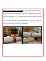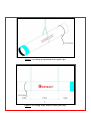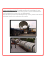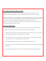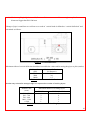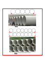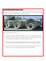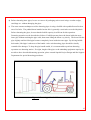
1
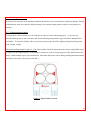
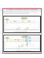
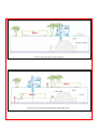
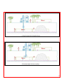
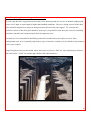
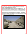
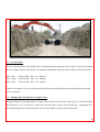
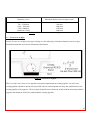
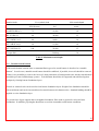
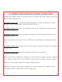
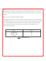
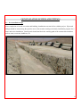
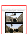
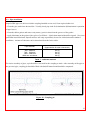
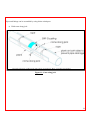
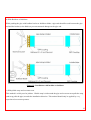
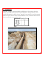
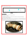
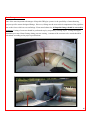
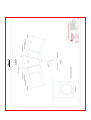
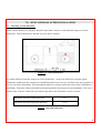
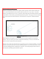
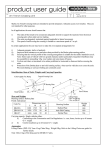
GLASS FIBER REINFORCED POLYESTER (GRP)
PIPES & FITTINGS
INSTALLATION MANUAL
INDEX
Page
Introduction......................................................................................................................................4
1.0
1.1
1.2
1.3
1.4
1.5
1.6
1.7
-
TRANSPORTATION, UNLOADING, STORAGE ...........................................................5
Transportation of pipes and fittings.........................................................................................5
Loading and unloading of pipes ..............................................................................................5
Loading and unloading of couplings and fittings ....................................................................9
Storage of pipes at job site.......................................................................................................9
Unloading, handling and storage of nested pipes ..................................................................12
Handling of lubricants ...........................................................................................................14
Transportation of pipes..........................................................................................................14
2.0 - SCHEMATIC ILLUSTRATION OF PIPE INSTALLATION STEPS .........................15
3.0 - TRENCH EXCAVATION AND PREPARATION FOR PIPE INSTALLATION ......18
3.1 - Basics of installation..............................................................................................................18
3.2 - General information on trench excavation ............................................................................20
3.3 - Sheet pile application during trench excavation....................................................................22
3.4 - Preparation of trench bedding................................................................................................23
3.5 - Trench width..........................................................................................................................24
3.6 - Multiple pipe installation in a single trench ..........................................................................24
3.7 - Cross-over of pipes................................................................................................................25
3.8 - Trench depth ..........................................................................................................................26
3.9 - Unstable trench bottom..........................................................................................................27
3.10 - Overflowing trench................................................................................................................28
4.0 - BEDDING AND BACKFILLING MATERIAL CLASSIFICATION ...........................29
2
5.0
5.1
5.2
5.3
5.4
5.5
5.6
5.7
-
INSTALLATION OF PIPES AND FITTINGS................................................................31
Pre-installation stage..............................................................................................................31
Lowering pipes onto the trench bed ......................................................................................32
Pipe installation .....................................................................................................................33
Angular deflection .................................................................................................................38
Flanged joints ........................................................................................................................39
Fitting connections ................................................................................................................40
Trenching on slopes...............................................................................................................45
6.0 - CONNECTION OF PIPES WITH RIGID STRUCTURES ...........................................47
6.1 - Repair / Pipeline closure pipes .............................................................................................49
7.0
7.1
7.2
7.3
7.4
7.5
7.6
-
SITE CONTROLS AFTER INSTALLATION ................................................................50
Checking vertical deflection. ................................................................................................50
Detecting (measuring) deflection ..........................................................................................51
Field hydrotesting ..................................................................................................................52
Filling the pipeline for hydrotesting ......................................................................................55
Allowable leakage .................................................................................................................56
Taking pipeline into operation...............................................................................................56
8.0
8.1
8.2
8.3
8.4
8.5
-
JOBSITE SAFETY PROCEDURES .................................................................................60
Pre installation stage..............................................................................................................60
Installation stage ....................................................................................................................60
While entering into a pipeline ...............................................................................................61
During repairs at job site .......................................................................................................61
Storage of chemicals and raw materials ..............................................................................62
3
INTRODUCTION
The purpose of this manual is to guide field teams to perform a proper installation of Superlit GRP pipes,
couplings and fittings. While using this manual, solid engineering practices and common sense should always
be taken into consideration and information provided on this manual should only be used as a guidance.
Specifications written for a particular project will always have a priority over the general guidelines mentioned
herewith. In case of a conflict or a contradiction, please contact Superlit Project Design and Site Support
Department.
Superlit recommends a whole study and evaluation of this manual before the start up of any jobsite activity. In
case of a need for further clarifications or practical trainings, SUPERLIT ACADEMY is ready for your
service. To get information about Superlit Academy or to join Academy Programs, please contact Superlit
staff.
With the company’s core principle of “Sustainable Superior Quality in Production and Service”, Superlit
Project Design and Site Support Department teams are always at your disposal whenever engineering support
or supervision is needed for project design, loading & unloading, handling, transportation, storage and
installation of pipes.
Superlit Pipe’s commitment on compliance with relevant standards and performance criteria is valid if the pipe installation is
performed in line with this manual. Superlit Pipe keeps the right to change any part of this document or as a whole, without prior
notification.
4
1.0 -TRANSPORTATION, UNLOADING, STORAGE
1.1 – Transportation of pipes and fittings
While transporting, moving, loading & unloading pipes and fittings at jobsite, maximum care should be
exercised to avoid any structural damage. The following points should be considered during these operations:
a) Identify proper lifting points and methods.
b) Identify proper moving methods and vehicles.
c) Visually control each moved item for damages or cracks.
d) Compare and control total quantity of moved or transported items with the order quantity.
e) Report any damage or a missing item.
Note: Damaged goods should not be used unless inspected and repaired by Superlit personnel.
1.2 - Loading and unloading of pipes
Loading and unloading operations are critical issues, therefore, techniques which will be used during these
operations should be determined based on site conditions. While loading or unloading and placing pipes on
the ground, prevent any impact with rigid objects to avoid structural damage.
Loading and unloading of pipes with DN ≥ 300mm should be exercised with an appropriate loading equipment
or machine. Based on pipe diameters, lengths and weights, as well as jobsite conditions, crane-lifting strap
method or forklift can be used for these operations.
5
Loading and unloading with crane and lifting strap: Pipes can be lifted either with one or two lifting
straps, however, for an easier balancing control while lifting, two lifting straps usage is recommended. With
one lifting strap, the strap should be fastened at pipe’s center of gravity. With two lifting straps, fastening
points should be as per the below illustration. Both methods should be exercised very carefully, fastening
points should be controlled and secured. To prevent any possible accidents, ensure that there is nobody under
the pipe while lifting.
Guide ropes tied around the pipe can be used to have manual control over the pipe while it is in the air, This
method is strongly advised particularly in high winds. Pipe direction control with guide ropes should be
performed at a distance, should not be done from underneath the pipe.
6
Figure 1: One lifting strap method (with a guide rope)
Figure 2: Two lifting straps method (with a guide rope)
7
Loading and unloading with forklift: This method is generally used for factory loadings or for wagon
loadings of railway transportation. However, since there is generally no need for a forklift at infrastructure
jobsites, unloading at jobsites is performed with crane-lifting strap method.
Ensure that forklift is operated by a licensed forklift operator. Pipes should be placed on wooden cradles, and
forklift should lift the pipe with the cradle as shown on below picture.
8
1.3 – Loading and unloading of couplings and fittings
Superlit GRP pipes are generally delivered with a coupling installed on one end. If there is a special
requirement or if additional couplings are required, couplings can be delivered separately as bundles.
Regardless of its dimensions, every fitting should be carried and unloaded with maximum care. In case fittings
are delivered plain (without external packaging), determination of lifting points and unloading techniques are
critical issues. For unloading of fittings with packaging, pipe unloading methods can be used.
In any case, center of gravity and balanced distribution of mass factors should always be taken into account
while lifting, loading and unloading of fittings.
1.4 – Storage of pipes at job site
a) The storage area should be flat, leveled and clear of objects such as rocks, stones, sharp edges, etc.
b) Pipes can be stored in piles to minimize the storage area within the allowed limits.
c) While storing the pipes as piles, wooden cradles should be placed between pipe levels. The first level
pipes should be supported with wooden wedges to prevent sliding.
d) It is recommended to store pipes on flat timbers to facilitate placement and removal of lifting slings
around the pipe, as well as easy handling of pipes with a forklift.
e) Flat timbers should be placed at a distance of ¼ of pipe length from each pipe end.
f) If couplings are delivered as bundles, couplings should be stored at horizontal position to prevent radial
deflection.
g) The storage ground should be resistant to heavy loads and should not be exposed to strong winds.
9
h) Maximum piling height is around 2,5 meters. It is not recommended to store pipes as piles for
diameters bigger than DN 1200 mm.
Change of pipe’s round form to oval form as a result of vertical loads is defined as “vertical deflection” and
calculated as follows:
Figure 3 : Vertical deflection
Maximum allowed vertical deflection should not exceed below values while storing the pipes as piles (stacks).
Stiffness Class
Maximum Deflection
(SN)
(% diameter)
2500
2.5
5000
2.0
10000
1.5
Table 1: Maximum vertical deflection
Another way to describe storage height is to express the number of stacking layers.
Diameter DN
( mm )
Maximum number of stacking layers
SN 2500
SN 5000 & 10000
200 – 450
4
5
500 – 700
3
4
700 – 900
2
3
1000 – 1200
2
2
> 1500
1
1
Table 2: Maximum number of stacking layers
10
Figure 4: Storage of pipes as a single level
Figure 5: Storage of pipes as piles (2 layers)
11
1.5 – Unloading, handling and storage of nested pipes
Pipes which will be shipped to far destinations can be shipped as nested (smaller diameter pipe placed inside
bigger diameter pipe) to reduce transportation costs. These pipes are packed in a special way and may require
case specific procedures for unloading, handling, storing and transporting.
General recommendations are as follows:
a) Always use 2 lifting slings while lifting nested pipes. Since the weight of nested pipes will be much
higher than the weight of a single pipe, ensure that lifting slings are strong enough to handle the total
load. Consult Superlit for lifting points and lifting method for nested pipes.
,
b) Storing pipes as nested is a prefered application in many cases due to less storage cost and space.
However, do not store nested pipe bundles as stacks and always store nested pipes as a single level.
c) To prevent movement of inner pipes while transporting, special packaging techniques are used for
nested pipes. Do not release original packaging of nested pipes until installation.
12
d) Before denesting inner pipes, be sure to remove all packaging such as steel strips, wooden wedges,
sand bags etc. without damaging the pipes.
e) The most common technique used for denesting pipes is using a forklift with a padded boom fixed on
one of its forks. The padded boom installed on the fork is generally a steel tube covered with plastic.
Before denesting the pipes, be sure that the forklift capacity is sufficient for this operation.
Denesting operation can be described as follows: Forklift operator places the boom inside the most
inner pipe without touching the pipe walls, then starts lifting the boom very slowly. The boom lifts the
pipe slightly until the lifted pipe becomes completely loose inside the outer pipe. By driving forklift
backwards, lifted pipe is taken out of the bundle. After each denesting, pipes should be visually
controlled for damages. To keep the pipe bundle stable, it is recommended to perform denesting
operation at a denesting station. If weight, length of the pipes or the unloading equipment capacity do
not allow above described denesting operation, please consult Superlit Project Design and Site Support
Department for special denesting procedures.
Figure 6 : Denesting with a forklift
13
1.6 – Handling of lubricants
Lubricants used for pipe and coupling installation should always be stored in their original packaging. During
transportation, make sure that the original packages are mounted tightly and not subject to any damage or
leakage.
1.7 – Transportation of pipes
Transportation vehicle should never be loaded over capacity while transporting pipes. To prevent any
structural damage due to the movement and vibration during transportation, pipes should be detached from
each other. To keep the stability and to prevent movement, pipes should be tightly packaged and supported
with wooden wedges.
Maximum loading height for pipes is 2,5m. Pipe bundles should be fastened on the vehicle with pliable straps
or ropes over the support points. If steel strips or chains are used for fastening, place fabric pads between the
strips / chains and the pipe to prevent abrasion. Maximum deflection values during loading and transportation
should not exceed the values given on Table 1.
Figure 7: Pipes loaded on truck
14
2.0 – SCHEMATIC ILLUSTRATION OF PIPE INSTALLATION STEPS
In this section, pipe installation steps are described briefly with drawings to give a general overview. At
further sections, installation steps mentioned hereby are explained in details.
15
16
17
3.0 – TRENCH EXCAVATION AND PREPARATION FOR PIPE INSTALLATION
Pipe installation methods for Superlit GRP pipes vary based on stiffness, burial depth, native soil
characteristics and backfill material.
Initial and long term vertical deflection values should never exceed the values given on Table 1, regardless of
the installation method and conditions. Otherwise, pipe performance might not meet the expectations.
3.1 - Basics of installation
Superlit GRP pipes are designed to provide a continuous excellent performance for long years if the
installation is performed correctly as per the instructions. Therefore, trenching, bedding and backfilling
specifications and methods should be evaluated very carefully.
Engineers have found out through considerable experience that ideal materials for bedding and backfilling are
properly compacted granular materials. However, to reduce field costs, excavated trench soils are very often
used as pipe zone backfill. In such a case, excavated trench soils should be analyzed to determine the
suitability of usage as backfill material.
Superlit engineers always recommend compacted granular material for bedding and backfilling.
18
19
Figure 8
3.2 - General information on trench excavation
Following points should be considered during trench excavation:
a) Take necessary safety precautions to ensure a safe working environment.
b) Prevent water penetration into the trench.
c) During excavation, make sure that trench walls keep vertical position.
d) For a flat bedding, remove all obstacles and sharp edges such as rocks, gravels, concrete, etc. from the
trench.
e) Remove all organic items such as plants, tree roots, etc. from trench ground.
f) Ensure that trench ground is strong and stable.
g) If the trench ground is not stable enough, increase trench depth for stabilization works.
h) Discharge water (if there is any) from the trench before bedding preparation.
i) When the underground water level is high, it might cause pipes to float. To prevent floatation, increase
the trench depth to increase the height of backfilling.
j) Ensure that trench width is sufficient enough for bedding and backfilling compaction works.
k) Ensure that excavated materials are piled at a distance from the trench to avoid the possibility of rolling
back into the trench.
20
Trench ground stabilization works (Foundation)
Bedding after ground stabilization
21
3.3 – Sheet pile application during trench excavation
Trench walls should be supported with sheet piles if the natural ground soil is loose or unstable, underground
water level is high, or trench depth is higher than standard conditions. However, during removal of the sheet
piles, backfill compaction is subject to disruption which decreases the pipe support. To overcome this
problem, removal of the sheet piles should be done step by step and after each sheet pile removal, backfilling
should be controlled and compacted until desired compaction level.
Crushed rock is recommended as backfilling material for trenches where sheet piles are used. Since
underground water level is generally high in these types of trenches, crushed rock size should be big enough to
resist water washout.
Superlit engineers advise trench width, where sheet piles are used, as “DN+2m” up to nominal pipe diameter
DN 1000 and as” 3xDN” for nominal pipe diameter DN 1000 and above.
22
3.4 - Preparation of trench bedding
Trench bedding should be flattened, leveled and compacted all along the trench. Under unstable soil
conditions, trench depth and bedding thickness can be increased.
After trench excavation, bedding should be prepared to provide durable and stable support for pipe. Pipe
bedding should not be less than 15cm in height and should be prepared with compacted granular material at
minimum 90% Standard Proctor Density or any other suitable bedding material at minimum %95 Standard
Proctor Density.
Bedding depth should be increased if there are unstable, loose or soft soil conditions. If bedding material is
sandy, bedding material should be moisturized and should be compacted with vibrating compactors. Bedding
should always be flat and leveled with the trench bottom.
23
3.5 - Trench width
Trench width should be wide enough to place fittings and connection parts, and to allow a convenient working
space for field teams for compaction. For standard installations, minimum trench width is advised as follows:
DN < 600,
Trench width = DN + (2 x 300mm)
DN < 1000,
Trench width = DN + (2 x 400mm)
DN ≥ 1000,
Trench width = DN + (2 x 450mm)
If there are unstable, loose or soft soil conditions, based on the pipe stiffness and trench depth, trench width
can be increased.
3.6 – Multiple pipe installation in a single trench
During installation of multiple pipes in a single trench, distance between any of the 2 pipes is determined with
the formula (r1+ r2) / 2 whereas r1: radius of the first pipe and r2: radius of the second pipe. Complying with
the formula, Superlit recommends below values for the distance of pipes in the same trench:
24
Diameter ( mm )
Minimum distance between pipes ( mm )
200 – 600 mm
300 mm
600 mm
700 – 1200 mm
1300 – 2000 mm
1000 mm
2100- 3000mm
1500 mm
3000 mm ve üstü
2000 mm
Table 3 : Minimum distance between pipes
3.7 – Cross-over of pipes
In case of cross over of pipes (one pipe crossing over the other pipe), minimum distance between 2 pipes
should be determined as per below illustration and formula.
Figure 9: Cross-over of pipes
There are some cases where a new pipeline route passes underneath an existing pipeline. In such cases,
existing pipeline should be shut down (if possible) and excavation should start only after stabilization of the
existing pipeline with supports. The new pipes should be lowered into the trench without interacting with the
supports and should be laid slowly underneath the existing pipeline.
25
After placing new pipes, backfill material should be applied to close the gap between the two pipes and should
be compacted by hand. It is also recommended to add a small amount of cement in the back fill material.
3.8 – Trench depth
While determining the trench depth, intended purpose of service, design of the pipeline, pipe characteristics,
trench soil characteristics, static-dynamic load combinations should be taken into consideration.
Trench depth should be sufficient to prevent conveyed fluids to freeze. Sufficient cover (backfill and final
backfill) should be provided to prevent pipe flotation in potentially high ground water areas. Generally
accepted trench depths are as follows:
Pipe Stiffness
Trench depth
(SN)
(meter)
2500
1-3
5000
1-5
10000
1-7
Table 4: Trench depth
26
Surface loads
Live (wheel) load
Kilo Newton
Min. trench depth
lbf
meter
AASHTO H20 (C)
72
16,000
1.0
BS 153 HA (C)
90
20,000
1.5
ATV LKW 12 (C)
40
9,000
1.0
ATV SKW 30 (C)
50
11,000
1.0
ATV SLW 60 (C)
100
22,000
1.5
Railway
3.0
Cooper E80
Table 5: Minimum trench depth
3.9 – Unstable trench bottom
If the trench bottom contains loose or montmorillonit type soils, trench bottom is described as “unstable
bottom”. In such cases, unstable trench bottom should be stabilized, if possible, loose soil should be removed.
If there is no possibility to remove the loose soil, then penetration of underground water into the trench bottom
should be prevented with drainage systems. Trench bottom should also be supported and stabilized against
collapse by forming bottom foundation layers.
Gravels or crushed rocks can be used to form bottom foundation layers. Height of the foundation should be
20 cm minimum and can be increased based on trench bottom soil characteristics. Standard bedding should be
applied over the foundation layer.
To prevent loss of pipe support and to strengthen foundation, filter cloth or geotextile can be laid onto
foundation. In addition, pipe lengths should not exceed 6m at unstable trench bottom conditions.
27
3.10 – Overflowing trench
If the ground water level is rising onto the trench bottom, this case is described as “overflowing trench”.
Under this condition, ground water level should be decreased at least 20cm below the trench bottom before
bedding preparation.
Gravel or crushed rock should be used for bedding and backfill in such trenches. However, crushed rock size
should be big enough not to be dragged with the water flow. Pipes are subject to floatation in overflowing
trenches. Therefore, backfill & final backfill height and Standard Proctor Density should be increased. In
some cases, placement of additional weights onto the final backfill might be needed to prevent floating of
pipes.
28
4.0 – BEDDING AND BACKFILLING MATERIAL CLASSIFICATION
Bedding and backfilling materials are classified as follows according to AWWA M45, Fiberglass Pipe Design,
Manual of Water Supply Practices.
Soil stiffness category SC1 : Crushed rock containing less than 15 % of sand. (maximum 25 % passing
through 9.5 mm sieve and maximum 5% passing through No.200 sieve)
Soil stiffness category SC2 : Clean, coarse-grained soils (SW, SP, GW, GP and similar soil with maximum
12 % passing No 200 sieve)
Soil stiffness category SC3: Clean, coarse-grained soils (SW, SP, GW, GP and similar with minimum 12 %
passing No 200 sieve)
or
Sandy or gravelly fine-grained soils (CL, ML, CL-ML type soils with minimum 30 % retained on a No 200
sieve)
Soil stiffness category SC4: Fine-grained soils (CL, ML, CL-ML type soils with maximum 30 % retained on
a No 200 sieve)
Soil stiffness category SC5: Highly plastic and organic soils (MH, CH, OL, OH, PT)
SC1 type soils, with low sand and fine containment, provides maximum pipe support based on the compaction
level. Compaction of the material is easy and displays maximum support even under moisturized conditions.
SC2 type soils, with a high compaction level, displays a high pipe support.
SC3 type soils display lower pipe support compared to SC1 and SC2 category soils. Compaction requires
effort and high moisture conditions decrease the pipe support level.
29
SC4 type soils require geotechnical evaluation before used for bedding or backfilling. Compaction is difficult
and is desired level of compaction is directly dependent on moisture conditions. This type is of soil is not
suitable for bedding or backfilling at high backfilling levels, under traffic loads and if there is ground water in
the trench.
SC5 type soils are not suitable for bedding or backfilling.
* Bedding material characteristics are very important for a proper support for the pipes. Generally bedding
and backfilling materials are preferred to have the same characteristics. If the excavated material is preferred
to be used as backfilling material, characteristics of the excavated soil should be analyzed for suitability.
Another critical point to be taken into consideration is the possibility of experiencing different soil
characteristics along the pipeline.
Nominal Diameter
(DN)
DN =< 450
450 < DN =< 600
600 < DN =< 900
900 < DN =< 1200
1200 <DN
Maximum particle size
(mm)
13
19
25
32
38
Tabel 6 : Maximum particle size
30
5.0 INSTALLATION OF PIPES AND FITTINGS
5.1 – Pre-installation stage
After completion of trench excavation and bedding, installation can start in line with the project. Pipes and
fittings should be stored along the pipeline next to the trench according to the daily installation program for a
faster and easier installation. Stored goods should not block the working path of the construction machines
such as crane, excavator, bulldozer, etc.
31
5.2 – Lowering pipes onto the trench bed
Lifting straps should be tied around the pipe from the appropriate lifting points. While lifting fittings, special
lifting and alignment requirements should be taken into consideration. (For instance, the arm angle of the Tee
part). Lifting can be performed with a crane or with the excavator arm and pipe should be lowered onto the
bedding slowly. During lifting and lowering inside the trench, field teams instruct directions to the excavator
operator to make sure that pipe will be placed at the right location. Pipe should be lowered closer to the
previously installed pipe and should be carefully aligned.
32
5.3 – Pipe installation
Superlit GRP pipes are delivered with a coupling installed on one end, if not required otherwise.
--Clean the pipe ends from dust and dirt. Visually check pipe ends for delamination (Delamination is partition
of pipe layers)
--Clean the rubber gasket and remove any stones, gravel or dust from the grooves of the gasket.
--Apply lubricants on the gasket with a piece of soft fabric. Lubrication material should be organic. Never use
petroleum based lubricants. Superlit advises soft soap or paraffin to be used as a lubricant under standard
conditions. Amount of lubricant can be determined from the below table:
Pipe diameter
Lubricant amount
(Approximate for each connection)
200 – 600 mm
700 – 1200 mm
1300 – 2000 mm
2000 mm and above
0.2 kg
0.4 kg
0.6 kg
0,8 kg
Table 7 : Lubricant amount
For easier assembly of pipes, a pit should be excavated for the coupling to settle. After assembly of the pipe to
the previous pipe, coupling pit should be filled with backfill material and should be compacted.
Figure 10 : Coupling pit
33
Pipes and fittings can be assembled by using below techniques:
a) With come-along jack:
Figure 11: Come along jack
34
b) With Backhoe or Bulldozer:
While pushing the pipe with backhoe bucket or bulldozer blade, a plywood should be used between the pipe
end and the bucket (or the blade) to prevent structural damage on the pipe end.
Figure 12 : Installation with backhoe or buldozer
c) With pliable strap and excavator arm.
This method is widely used at jobsites. Pliable strap is tied around the pipe and excavator arm pulls the strap
(and strap pulls the pipe) towards the installation direction. This method should only be applied by very
experienced excavator operators.
35
In all above mentioned methods, pipe should be inserted into the coupling until pipe touches the stopper of the
coupling. For big diameter pipes, field technicians can enter the pipe after the installation to control the
alignment of the stopper and the pipe. However, for small diameter pipes, a different technique should be used
to ensure touching of the pipe and the stopper, since there is no possibility to get into the pipe. In such cases,
distance from the coupling outer end to the stopper is measured and marked on the pipe, and pipe is pushed
inside the coupling until marked section meets the coupling end.
Figure 13 : Pipe insertion to the coupling
36
37
Figure 14: GRP pipe –coupling connection detail
5.4 – Angular deflection
Superlit GRP couplings are manufactured with full face EPDM gaskets. When compared with similar
couplings, Superlit GRP couplings guarantee a complete leak tightness. The biggest advantage of these
couplings is their suitability for angular deflection. Especially for longer pipelines, it is possible to rotate the
pipeline with angular deflections from the couplings, without any necessity for additional elbows. Below are
the maximum allowable maximum deflection values.
Diameter (mm)
Angular deflection
(degrees)
200 - 350
400 – 500
600 – 900
1000 – 1800
> 1800
3
3
2
1
0.5
Table 8 : Allowable angular deflection values
38
Before applying an angular deflection, pipe should be installed to the pipeline at a straight position, then
angular deflection should be performed.
Figure 15: Angular deflection
5.5 – Flanged joints
Flanged connections are used at several conditions such as;
--Vane and pump connections,
--At transitions between different types of pipes (such as connection of a steel pipe with a GRP pipe),
--At water tank or manhole connections.
While connecting two flanges, alignment of bolts is a very important issue to avoid loading bending stress on
bolts. Flange thicknesses should be taken into consideration determine the size of the bolts, nuts and washers.
For tightening torques, please consult Superlit engineering teams.
39
5.6 – Fitting connections
One of the most important advantages of Superlit GRP pipe systems is the possibility of manufacturing
project-specific custom designed fittings. However, fittings are the most critical components of the pipelines
due to the forces which occurs on fittings. If not stated otherwise, all Superlit fittings should be encased in
concrete. Casting of concrete should be performed step by step and by forming layers. Fittings and pipes
should be prevented from floating during concrete casting. Amount of the concrete to be casted should be
calculated according to the project specifications.
40
41
Figure 16
42
Figure 17
43
Figure 18
44
Figure 19
5.7 – Trenching on slopes
If the slope of the trench ground is 150 or higher, GRP pipes should be manufactured with ribs. In such
trenches, it is not suitable to use rounded gravels for bedding and backfilling, since rounded gravels are subject
to washout which leads to pipe support to reduce. Advise of Superlit for bedding and backfilling material in
sloped trenches is crushed rocks with internal friction angle 420.
The most critical issue regarding sloped pipelines is the risk of backfilling and final back filling erosion.
Therefore, erosion risk should be taken into account while determining the backfill material and compaction
level. Erosion is a result of strong underground water flows, rain, wind and dust storms. In any of these
conditions, granular backfilling material should be resistant to erosion. In some cases, methods such as rip-rap
(big rock pieces) placing, claying, asphalt application can be performed.
45
46
Figure 20
6.0 - CONNECTION OF PIPES WITH RIGID STRUCTURES
The most critical issue regarding pipe and rigid structure connection is the bending stress that may develop
when there is a differential settlement (movement) between the pipe and the rigid structure. To manage or at
least to lower this bending stress, short pipes should be used especially at connections with manholes, vanes
and pumps. There are 2 general methods used:
a) The coupling should be casted into the rigid structure. (Coupling should be positioned inside the rigid
structure model while casting the concrete)
b) A short pipe wrapped with rubber sealing should be used at connections with the rigid structure to
minimize the transition effect. (Rubber sealing should be placed before concrete casting with a recess of 25
mm)
Note: While casting concrete, ensure that the coupling keeps its original shape (roundness). Otherwise, pipe
might not slide into the coupling. Use a high stiffness pipe at connections with rigid structures. Ensure that
pipe is not subject to high deflections.
Short pipe length can be determined as 2xDN with an upper limit of 2 meters or as 1xDN with an upper limit
of 1 meter. Make sure that bedding and backfill of the short pipe is compacted properly.
Figure 21 : Short pipe connection
47
48
Figure 22
6.1 – Repair / Pipeline closure pipes
Repair and pipeline closure pipes are used under below conditions:
a) Field hydrotesting is generally applied at certain pipeline lengths, sections. To install testing caps to
the section ends, gaps are left along the pipeline. Pipeline closure pipes are used to close these gaps
after field hydrotesting.
b) For faster installation, in some cases installation starts from both ends of the pipeline route. At the
junction point, pipeline closure pipes are used to complete the pipeline.
c) Defective sections of a pipeline can be detected during field hydrotesting. In some cases, these
detected parts are needed to be replaced if there is no possibility to repair the crack with hand
lamination. In such cases, repair closure pipes are used to close the pipeline.
Before placing the repair / closure pipe, it should be controlled whether or not both sides of the pipeline are at
the same level and axis. After cutting repair/closure pipe at the required length, mechanical couplings should
be assembled on both ends. When repair / closure pipe is placed in the gap, pipe should be aligned to be on
the same level and axis with both pipeline ends. (For a more effective connection, repair / closure pipe length
is advised to be 20mm shorter than the pipeline gap). After ensuring correct alignment, both mechanical
couplings should be pulled over to the pipeline. During pulling over, gasket of the coupling should not bend.
When coupling pull over and alignment is completed, bolts of the mechanical couplings should be tightened
with a torque wrench at the recommended torque value.
Figure 23 : Application of repair / closure pipes
49
7.0 – SITE CONTROLS AFTER INSTALLATION
7.1 – Checking vertical deflection.
Initial vertical deflection of the pipes should be kept under control to reach allowable long term vertical
deflections. Vertical deflection is defined as per the below formula:
Figure 24 : Vertical deflection
It is rather difficult to measure long term vertical deflections. (Long term deflections generally appear
minimum 6 months after the completion of installation and in most cases it is not allowed to stop a pipeline in
service to measure deflections). Recommended method is to measure deflections 3 days after completion of
backfilling. Deflection controls should be performed parallel to the progress of pipe installation. This way it
will be easier to detect a deflection at an initial stage and to take immediate corrective actions.
Maximum allowable initial deflection
% 2.5
Maximum allowable long term deflection
% 5.0
Table 9 : Allowable deflection
50
7.2 – Detecting (measuring) deflection
Whenever it is possible for a person to enter a pipeline (which is generally valid for diameters 800mm and
above) vertical internal diameter can be measured with a laser-meter device every 3 meters. For smaller
diameters, pig method can be used. Pig is a wooden disc with a height equal to the allowable deflected vertical
internal diameter. In this method, pig is pulled through inside the pipeline. If the pig gets in from one end and
gets out from the other end without obstruction, vertical deflection is accepted to be within the allowable
limits.
Figure 25 : Pig application
Superlit emphasizes the importance of performing deflection measurements parallel to the installation
progress. This way it will be easier to detect a deflection at an initial stage. The cost, as well as the time
spent, for corrective actions will be much economical.
Deflection values outside of the allowable limits are generally an outcome of improper backfilling. If an initial
deflection out of the allowable limits is detected, backfilling should be excavated, especially bottom sections
of the pipe backfilling should be controlled and re-compacted. After ensuring that pipe bottom sections are
well compacted, backfilling operation should be repeated.
51
After this corrective action, deflection measurements should be repeated monthly. After 3 or 4 additional
controls, if the vertical deflection stays lower than 5%, corrective action can be considered as successful. If
vertical deflection is measured as more than 5% in any of these additional controls, corrective action should be
repeated right from the beginning.
7.3 – Field hydrotesting
Just like all other types of pipes, GRP pipelines should also be tested before taking the pipeline into operation.
Field tests can be performed with water for pressured or non pressured pipelines. The purpose of field
hydrotesting is to detect any leakage points through the pipeline.
If the pipeline is tested as a whole, it is rather difficult to detect exact locations of leakages; it is also difficult
and costly to fill / unfill the whole pipeline. Therefore, recommended test lengths are 250-1000m based on the
pipeline conditions.
Below points should be checked before field hydrotesting:
a) Make sure that all truss blocks and rigid structures made of concrete are completed at least 7 days before
the hydrotest. Ensure that concrete of the structures has completed curing and structures are rock solid.
b) Ensure that all testing equipment are functional and in good condition.
c) Close and seal the ends of the pipeline section subject to testing with end caps.
d) Ensure that end caps are supported with anchors to resist test pressure.
For visual inspection of the couplings during hydrotesting, 1/3 of top of the couplings are not backfilled.
Safety precautions should be applied around the pipeline, if possible, tested section of the pipeline should be
isolated from human access before starting hydrotest. After completion of the hydrotest, unfilled top sections
of the couplings should immediately be filled with backfill material.
52
53
Figure 26
54
Figure 27
Note: During hydrotesting of large diameter GRP pipes with nominal pressure 10 bars and above, couplings
might rotate. For high pressure pipelines, test pressure should not be increased if the coupling tops are left
unfilled for visual inspection. If a coupling rotation is detected, test should be immediately stopped, coupling
should be aligned and test should be repeated from the beginning.
7.4 – Filling the pipeline for hydrotesting
Pipeline should be filled from the lowest point (level) and air should be to expelled from the highest point
(level) of the pipeline through air valves. Flow rate of filling should not exceed 5-10 % of the pipeline
nominal design flow rate. If it is not possible to fill the pipeline from the lowest point, additional air valves
should be installed.
Below outlined method can be followed:
•
Increase the pressure to 2 – 3 bar.
•
Keep the pipeline under this pressure for 12 hours for stabilization.
•
Shut off all air valves after ensuring that all air is expelled from the pipeline.
•
After stabilization period, increase the pressure by 2 bars every 30 minutes.
55
•
Continue to increase the pressure (as explained above) until the applied pressure is 1,5 times of the
nominal operation pressure of the pipeline. (Field hydrotest pressure is defined as the 1,5 times of the
nominal operation pipeline pressure)
•
Measure the test pressure from the lowest point of the pipeline.
7.5- Allowable leakage
Most project specifications allow pressure loss or leakage on a pipeline up to a certain limit. According to
BS 8010: Part 2.5:1989, allowable leakage in 24 hours is 0.02 liter/ mm.
7.6 – Taking pipeline into operation
Following points should be considered while taking the pipeline into operation:
a) Keep filling flow rate at %5-15 of the nominal operational flow rate of the pipeline.
b) At pressured pipelines, ensure that distance between the air valves is around 500-750m.
c) Air valve diameters should be in accordance with d/DN = 1/10 or 1/15, whereas “d” represents air
valve diameter.
d) Ensure that all air is expelled from the pipeline.
e) Do not use rapid closing vanes.
f) To avoid sudden stopping and running of pumps (which causes water hammer), take necessary
precautions.
g) Avoid air penetration from water intake structure into the pipeline at gravity pressured pipelines.
h) When pipeline is discharged partially or completely, repeat the steps mentioned above while re-filling
the pipeline.
56
57
Figure 28
58
Figure 29
59
Figure 30
8.0 – JOBSITE SAFETY PROCEDURES
8.1 – Pre installation stage
a) All site personnel should complete technical and safety trainings regarding jobsite activities including
loading, unloading, storing and installation before accessing to the jobsite.
b) “Jobsite Safety Procedures” booklet should be prepared and distributed to all jobsite personnel.
Warning labels and plates should be placed at appropriate places at jobsite.
c) During safety trainings, prior accidents and experiences should be presented by pictures and videos,
undesired outcomes of the accidents should be emphasized. It is vital to persuade and convince job site
personnel for the importance of jobsite safety to be able to enforce and apply the procedures strictly.
d) A safety supervisor should be assigned. Responsibilities, duties and authority of the safety supervisor
should be clearly identified and declared to all job site personnel.
e) Safety equipment such as helmets, safety shoes, safety gloves, etc should be provided and consigned to
each site personnel with a signed receipt declaration.
f) Site personnel should strictly be controlled in terms of utilization of the safety equipment.
g) Safety equipment supplied should be quality certified by independent accredited agencies.
h) Periodic maintenance and controls on safety equipments should be performed. Old, torn out or nonfunctional equipment should be replaced.
i) Personnel who does not obey and apply Jobsite Safety Procedures should immediately be discharged
from the jobsite area and pre-determined penalties should be exercised.
8.2 – Installation stage
a) Safety supervisor should strictly control whether or not installation activities are performed as
described during installation trainings. If there is a case which needs application of a non-standard
installation procedures, such a procedure should only be applied under the permission and supervision
of the Safety Supervisor.
b) Installation equipment should be free of damage and defects, and should be completley functional.
60
c) Machines and vehicles such as excavator, bulldozer, grader, etc should only be operated by certified
and licensed operators without any exception.
d) Make sure that communication system among jobsite personnel is clear, correct, uninterrupted and not
subject to misunderstanding or misinterpretation. (For instance, communication of a worker inside the
trench, with the crane operator lowering a pipe into the trench)
8.3 – While entering into a pipeline
While entering into a pipeline for control or repair purposes, below items should be taken into consideration:
a) Entrance into a pipeline should only be done with Safety Supervisor’s permission. Safety Supervisor
should evaluate all potential risks before permitting entrance. Personnel having health problems and
personnel who are not willing should not be allowed to enter into a pipeline.
b) If there is a necessity to perform gas and oxygen level tests, such tests should be performed by
authorized and certified personnel.
c) If the oxygen level inside the pipeline is not sufficient, entering personnel should be equipped with
oxygen tubes.
d) Personnel entering into a pipeline should be equipped with safety equipments and should always have a
spare lighting.
e) Communication between entering team and outside team should be clear and uninterrupted. For any
reason if communication is lost, inside team should immediately get out of the pipeline.
8.4 – During repairs at job site
a) Safety procedures exercised during installation should also be applied while removing a pipe or a
fitting from an installed pipeline.
b) Repairing works should be performed at a repairing station. Boundaries of the repairing station should
be clearly marked.
c) Any person other than authorized repair personnel should not enter to the repair station.
d) Repairing equipment should be functional, in good condition, clean and clear of defects.
e) Safety Supervisor should continuously inspect utilization of safety equipment during repairing.
61
f) Repair station environment should be clear of any possible fire risks.
g) Repair station should be equipped with fire extinguishers.
If the repair should be performed inside the pipeline;
h) Repairing personnel entering into the pipeline should wear isolated work suits and gas masks. If the
oxygen level is not sufficient, personnel should be equipped with oxygen tubes. Sufficient ventilation
should be supplied to remove the dust from the pipeline.
i) If the repair inside the pipe should be done at 2m height or more, suitable scaffolding should be
provided.
8.5 – Storage of chemicals and raw materials
a) Chemicals and raw materials which will be used for repairs should be stored in a closed and locked
storage room.
b) Storage room should have natural ventilation and should not be subject to high temperatures.
c) Storage room should be isolated from outer side conditions such as humidity, rain, snow, etc.
d) All chemicals and raw materials should be stored at their original packages.
e) Storage room should be equipped with fire extinguishers.
62