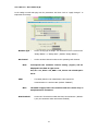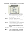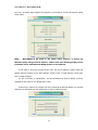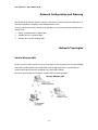
1
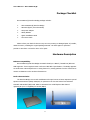
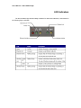
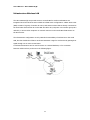
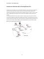
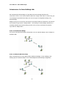
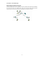
User’s Manual – WL11000SA-N (B)
The WL11000SA-N (B)
Wireless Bridge
The WL11000SA-N (B) is an 11 Mbps wireless bridge that allows the connections of two or
more remote Ethernet LANs into a single virtual LAN. Workstations on each of the remote LANs
may communicate with each other as though they were on the same physical LAN.
The Wireless Bridge can also function as an Access Point and provide transparent,
wireless data communications between the wired LAN (and/or within the wireless Network) and
fixed, portable or mobile devices equipped with a wireless adapter employing the same
modulation.
This solution offers fast, reliable wireless connectivity with considerable cost savings over
wired LANs (which include long-term maintenance overhead for cabling.)
1
User’s Manual – WL11000SA-N (B)
Table of Contents
Package Checklist
3
Hardware Description
3
LED Indicators
4
Applications
5
System Requirements
6
Installation
7
Configuration
8
Windows 95/98ME/2000/NT4.0 Installation
8
Network Configuration and Planning
13
Network Topologies
13
Ad Hoc Wireless LAN
13
Infrastructure Wireless LAN
14
Infrastructure Wireless LAN for Roaming Wireless PCs
15
Infrastructure for Inter-Building LANs
16
Troubleshooting
18
Compliances
19
FCC - Class B
19
CSA Statement (Canada)
20
CE Mark Declaration of Conformance
20
Specifications
21
Terminology
23
2
User’s Manual – WL11000SA-N (B)
Package Checklist
WL11000SA-N (B) Wireless Bridge package includes:
²
1 WL11000SA-N (B) Wireless Bridge
²
1 Antenna (dipole, omni-directional)
²
1 DC power adapter
²
1 Utility diskette
²
1 Quick Installation Guide
²
1 This User Guide
Please inform your dealer if there are any incorrect, missing or damaged parts. If possible,
retain the carton, including the original packing materials. Use them again to repack the
product in case there is a need to return it for repair.
Hardware Description
Ethernet Compatibility:
WL11000SA-N (B) Wireless Bridge can attach directly to 10BaseT (Twisted Pair) Ethernet
LAN segments. These segments must conform to IEEE 802.3 specification. The Bridge appears
as an Ethernet node and performs a routing function by moving packets from the wired LAN to
remote workstations on the wireless infrastructure.
Radio Characteristics:
The Wireless Bridge uses a radio modulation technique known as Direct Sequence Spread
Spectrum transmission (DSSS, CSMA/CA). It operates in the 2.4 GHz license-free Industrial
Scientific and Medical (ISM) band. Data is transmitted over a half-duplex radio channel
operating at up to 11 Megabits per second (Mbps).
3
User’s Manual – WL11000SA-N (B)
LED Indicators
The WL11000SA-N (B) Wireless Bridge includes five status LED indicators, as described in
the following figure and table.
4
User’s Manual – WL11000SA-N (B)
Applications
The WL11000SA-N (B) Series Wireless products offer a fast, reliable, cost-effective
solution for wireless client or remote Ethernet LANs access to the network in applications such
as:
²
Remote access to corporate network information
E-mail, file transfer and terminal emulation
²
Difficult -to-wire environments
Historical or old buildings, asbestos installations, and open areas where wiring is
difficult to employ,
²
Frequently changing environments
Retailers, manufacturers and banks that frequently rearrange the workplace and
change location
²
Temporary LANs for special projects or peak time
Trade shows, exhibitions and construction sites, which need temporary setup for a
short time period. Retailers, airline and shipping companies who need additional
workstations for a peak period.
²
Access to databases for mobile workers
Doctors, nurses, retailers, white-collar workers who need access to databases while
being mobile in the hospital, retail store or office campus.
²
SOHO (Small Office and Home Office) users
SOHO users who need easy and quick installation of a small computer network
functions.
²
Building-to-Building connectivity
Connect discreet sites into a single LAN, even when they’re separated by obstacles
such as freeways, railroads, or bodies of water that are practically insurmountable
for copper and fiber-optic cable.
5
User’s Manual – WL11000SA-N (B)
System Requirements
Before you install the WL11000SA-N (B) Wireless Bridge, be sure you can meet the
following requirements:
²
An A/C power outlet (100~240V, 50~60Hz) which will supply power for the Wireless
Bridge
²
An available RJ-45 (UTP) port on a 10Base-T or 10/100Base-T Ethernet hub or
switch.
²
802.11b/802.3 compliant Wireless/Ethernet adapters with TCP/IP compatible
protocol installed.
²
Web Browser for configuration.
6
User’s Manual – WL11000SA-N (B)
Installation
1.
Select the Site - Choose a proper place for your WL11000SA-N (B) Wireless Bridge. In
general, the best location to place the WL11000SA-N (B) is at the center of your wireless
coverage area, within line of sight to all your wireless devices.
2.
Attach the Antenna - Screw the antenna into the antenna connector (ANT) on the back
panel. Proper placement will improve performance. Try to place the access point in a position
that can best cover its BSS. Normally, the higher you place the antenna, the better the
performance.
3.
Connect the Ethernet Cable - The WL11000SA-N (B) can be wired to a 10 or 10/100
BASE-T Ethernet with a network device such as a hub or a switch. Connect into the RJ-45
connector socket on the back panel with category 3, 4 or 5 UTP Ethernet cable and an RJ-45
connector.
4.
Connect the Power Cable - Connect the power adapter cable to the 9V
DC power Socket on the rear panel.
Warning:
USE ONLY the power adapter supplied with the WL11000SA-N (B).
Otherwise, the product may be damaged.
Note:
The RS-232 Port is a reserve port. There is no any function or
configure interface in currently model.
7
User’s Manual – WL11000SA-N (B)
Configuration
The diskette labeled “Utility Diskette”, that comes with the package contains a utility program
for the WL11000SA-N (B) Wireless Bridge. Any updates can be downloaded from Eumitcom
Technology Inc. Web site at
http://www.eumitcom.com.
Warning:
Backup your utility diskette and use the copy as the working diskette
to protect the original from accidental damage.
The WL11000SA-N (B) can be configured over an Ethernet network using RJ-45 cable or
wireless device that link to this Wireless Bridge. You may connect the WL11000SA-N (B) to a
network device such as a hub or switch. Then, run the utility program, and configure the
WL11000SA-N (B) remotely as described below.
Windows NT/95/98/ME/2000 Installation
1.
Insert the WL11000SA-N (B) utility disk into the floppy drive on your PC, and then enter
the following command: A:\utility\setup.exe. Follow the on-screen instructions to install
the utility program.
2.
When you run the installed utility click on “AP/Bridge” and then select “Scan” from the
menu, the program will then detect all the WL11000SA-N (B) on the network.
3.
From the list of detected WL11000SA-N (B), select and double click on the unit you want
to configure. The web browser page will appear as follows:
8
User’s Manual – WL11000SA-N (B)
4.
Enter the password “WLAN_BRIDGE” This will take you to the home page.
5.
Click on “Bridge Information MIB”, “Bridge Control MIB”, “TCP/IP Settings” or “Change
Password” to select the page required.
The Bridge Information MIB screen displays the categories of information shown below.
9
User’s Manual – WL11000SA-N (B)
In the Bridge Control MIB page set the parameters and then click on “Apply Changes” to
implement the settings.
Network Type –
Set the serving type of Bridge. This field can be set to “Access Point”
“Bridge Master” or “Bridge Slave” (Default: “Bridge Master”)
DS Channel
Note:
–
Set the wireless channel number as the operating radio channel.
Corresponds the available channel setting (region) will be
displayed in the field of right corner.
FCC/IC: 1-11, ETSI: 1-13, MKK: 1- 14, France: 10-13 and Spain:
10-11.
SSID
-
This SSID (ESS-ID) is an identification code required for
communication in a wireless LAN. (Default: “BRIDGE”)
Note:
The SSID is upper/lower case sensitive and can consist of up to
32 alphanumeric characters.
RTS Threshold -
Set the RTS Threshold to enable the RTS/CTS mechanism. (Default:
2,305, the maximum values and means Disabled)
10
User’s Manual – WL11000SA-N (B)
For more security setting, click on the Configure encryption icon, and the Encryption page will
show as below
WEP
-
For more secure data transmission, set the “WEP” to “WEP_128” or
“WEP_64” to ensure wireless network security. The advanced Wired
Equivalent Privacy (WEP) is implemented in this device to prevent
unauthorized access. The 128 bits setting gives a higher level of security
but the setting must be the same as other clients in your wireless
network. (Default: Disabled)
Key Entry–
This field can be set to “Passphrase” or “Manual Entry”.
Select the “Passphrase” means the KEY ID value will be auto generated
by the internal algorithm according the string defined in Passphrase field.
Select the “Manual Entry” means the KEY ID values allow/need user key
in by manually. (2 characters of hex in each block)
Pass Phrase - The security key for WEP encryption is generated from your pass phrase
so it should be the same as all the other stations in your network
64-Bit Manual Entry:
Key 1~4 -
Key ID value, each Key ID contains 10 hex digits. Wireless devices can
communicate to each other depend on this Key ID element values are
exactly the same
Default Key ID -
Choose which Key ID value would be using to encrypt the data, the
value could be choose from 1 to 4.
128-Bit Manual Entry:
Key 1
-
Key ID value, each Key ID contains 26 hex digits. Wireless devices can
communicate to each other depend on this Key ID element values are
exactly the same
11
User’s Manual – WL11000SA-N (B)
The TCP / IP Setting page displays the categories of information and the parameters setting
shown below.
NOTE:
WL11000SA- N (B) build in the DHCP Client function, it means the
Wireless Bridge will get the IP address, subnet mask and default gateway values
from DHCP server while Wireless Bridge powers on the network.
If you want to set these yourself, please enter the new IP address, subnet mask and
default gateway properly in the “New Settings” section of the “TCP/IP Settings” screen then
click on “Apply Changes”.
For the convenient of identification, the WL11000SA-N (B) Wireless Bridge could be
assigned an alias name in the “Bridge Name” field.
A password is required to configure the WL11000SA-N (B) Wireless Bridge. We suggest
changing your password from the default value to ensure network security.
12
User’s Manual – WL11000SA-N (B)
Network Configuration and Planning
WL11000SA-N (B) Wireless Solution supports a stand-alone wireless network configuration, as
well as an integrated configuration with 10Mbps Ethernet LANs.
The WL11000 series wireless network cards, adapters, Access Point a nd Wireless Bridge can be
configured as:
²
Ad hoc for departmental or SOHO LANs
²
Infrastructure for enterprise LANs
²
Infrastructure for inter-building LANs
Network Topologies
Ad Hoc Wireless LAN
An ad hoc wireless LAN consists of a group of computers, each equipped with a wireless adapter,
connected via radio signals as an independent wireless LAN. Computers in a specific ad hoc
wireless LAN must therefore be configured to the same radio channel.
An ad hoc wireless LAN can be used for a branch office or SOHO operation.
13
User’s Manual – WL11000SA-N (B)
Infrastructure Wireless LAN
The WL11000SA-N (B) can provide access to a wired LAN for wireless workstations. An
integrated wired and wireless LAN is called an Infrastructure configuration. A Basic Service Set
(BSS) consists of a group of wireless PC users, and an Access Point that is directly connected to
the wired LAN. Each wireless PC in this BSS can talk to any computer in its wireless group via a
radio link, or access other computers or network resources in the wired LAN infrastructure via
the Access Point.
The infrastructure configuration not only extends the accessibility of wireless PCs to the wired
LAN, but also doubles the effective wireless transmission range for wireless PCs by passing their
signal through one or more Access Points.
A wireless infrastructure can be used for access to a central database, or for connection
between mobile workers, as shown in the following figure.
14
User’s Manual – WL11000SA-N (B)
Infrastructure Wireless LAN for Roaming Wireless PCs
The Basic Service Set (BSS) is the communications domain for each Access Point or Bridge. For
wireless PCs that do not need to support roaming, set the domain identifier (SSID) for the
wireless card to the BSS ID of the Access Point or Bridge to which you want to connect. Check
with your administrator for the BSS ID of the Access Point or Bridge to which he wants you to
connect.
A wireless infrastructure can also support roaming for mobile workers. More than one Access
Point can be configured to create an Extended Service Set (ESS). By placing the Access Points
so that a continuous coverage area is created, wireless users within this ESS can roam freely. All
WL11000 series wireless network adapters and WL11000SA-N series product within a specific
ESS must be configured with the same SS ID.
15
User’s Manual – WL11000SA-N (B)
Infrastructure for Inter-Building LANs
WL11000SA-N (B) Wireless Bridge is a high data rate wireless bridge that allows the
connections of two or more remote Ethernet LANs into a single virtual LAN. To achieve the goal
of connecting the separated wired LANs, there are two types of configurable settings in the
Wireless Bridge.
Bridges serving as root units are connected to the primary backbone infrastructure and should
set the Network Type mode to “Bridge Master”. Those acting as remote Bridges, attached to a
secondary backbone and communicating via radio to the root unit, should have the Network
Type mode be “Bridge Slave”.
Point-to-Point Wireless Bridge
The Point-to-Point Wireless Bridges configuration uses two Wireless Bridge units to bridge two
individual LANs.
Point-to-Multipoint Wireless Bridge
When connecting three or more LANs (usually in different buildings, or inter-building), each
building requires a Wireless Bridge. This is called Multipoint Wireless Bridge configuration.
16
User’s Manual – WL11000SA-N (B)
Wireless Bridge with Wireless End Nodes
A Wireless Bridge Master has the capability to serve the wireless client nodes from in-building.
The wireless client device can establish radio contact with the Wireless Bridge Master and have
wireless access to all local and remote LANs, workstations, and network resources.
17
User’s Manual – WL11000SA-N (B)
Troubleshooting
Check the following items before contacting Technical Support.
1.
If the WL11000SA-N (B) cannot be configured using the web browser:
²
Remove power from the WL11000SA-N (B).
²
Push in the reset button located on the back of the WL11000SA-N (B).
²
While holding in the button, apply power to the Wireless Bridge.
²
Wait until both the wireless Activity LED, and the wireless Link LED both start to flash on
and off together.
²
Release the Push Button and the LEDs will turn off. You are now in the Control Mode.
²
Select the desired function by pressing the reset button (Note: hold the button until the
LEDs change to the next configuration).
The function changes to the next in sequence every time the Push Button is pressed. The
pattern repeats (Function: 0,1,2,3,0,1,2,3,0,...) as the Push Button is pressed repeatedly. The
following table shows the supported LED patterns and functions:
Functio
RF Link
RF Activity
Action
n
LED
LED
0
OFF
OFF
- No Action, will boot normally
1
OFF
ON
- Revert to Factory Default settings.
2
ON
OFF
- Force boot from Primary code image
3
ON
ON
- Reserved, (for now will boot normally)
Control Mode is automatically exited when the Wireless Bridge has not detected any
Push Button pressed for approx. 3 seconds. At that point it will flash both LEDs twice, indicating
it is proceeding with the boot.
18
User’s Manual – WL11000SA-N (B)
Compliances
FCC Class B Certification
1.
This device complies with Part 15 of the FCC Rules. Operation is subject to the following
conditions: This device may not cause harmful interference.
2.
This device must accept any interference received, including interference that may cause
undesired operation.
Warning! This equipment has been tested and found to comply with the limits for a Class B
digital device, pursuant to Part 15 of the FCC Rules. These limits are designed to provide
reasonable protection against harmful interference in a residential installation. This equipment
generates, uses and can radiate radio frequency energy and, if not installed and used in
accordance with the instructions, may cause harmful interference to radio communications.
However, there is no guarantee that interference will not occur in a particular installation. If
this equipment does cause harmful interference to radio or television reception, which can be
determined by turning the equipment off and on, the user is encouraged to try to correct the
interference by one or more of the following measures:
²
Reorient or relocate the receiving antenna.
²
Increase the distance between the equipment and receiver.
²
Connect the equipment into an outlet on a circuit different from the one that the receiver
is connected to.
²
Consult the dealer or an experienced radio/TV technician for help.
This device requires a radio license, unless it (including antenna) is installed totally inside a
building. (User must obtain this license from Industry Canada).
19
User’s Manual – WL11000SA-N (B)
CSA Statement (Canada)
This digital apparatus does not exceed the Class B limits for radio noise emissions from digital
apparatus set out in the Radio Interference Regulations of Industry Canada.
CE Mark Declaration of Conformance
This is to certify that this product complies with ISO/IEC Guide 22 and EN45014. It conforms to
the following specifications:
EMC: EN55022 (1988)/CISPR-22 (1985) Class B
IEC 61000-4-2(2000)
4kVCD/8kVAD
IEC 61000-4-3(2000)
3V/m
IEC 61000-4-4(2000)
1kV- (power line)
IEC 61000-4-6(2000)
3Vrms
IEC 61000-4-11(2000)
3Vrms
20
User’s Manual – WL11000SA-N (B)
Specifications
Model
WL11000SA-N (B)
Maximum Channels
US & Canada: 11, Europe (ETSI): 13, Japan: 14
Maximum Clients
1024
Data Rate
1, 2, 5.5, 11 Mbps per channel
Network Configuration
Point to Point
Point to Multi-Point
Operating Frequency
USA, Canada & Europe (ETSI): 2.400-2.4835 GHz,
Japan: 2.400-2.497 GHz
Sensitivity
1, 2, 5.5 Mbps: -80 dBm, 11 Mbps: -76 dBm typical
Modulation
CCK, BPSK, QPSK
Power supply
Input: 100-240 AC, 50-60 Hz
Output: 9 VDC, 1A
Output Power
+13 dBm minimum
Physical Size
5.12 x 7.09 x 1.58 in, (13 x 18 x 4 cm)
Weight
12.9 oz (365 grams)
LED Indicators
Power, Ethernet Link, Ethernet Activity, Wireless Link, Wireless Activity
Network Management
HTML web-browser interface
Windows 95/98/ME/NT/2000 utility
Operating Systems
Windows 95/98/ME, Windows NT/2000
21
User’s Manual – WL11000SA-N (B)
Temperature
Operating: 32 to 122 ℉ (0 to 50 ℃)
Storage:
32 to 158 ℉ (0 to 70 ℃)
Humidity
5% to 8% (non-condensing)
Compliances
CE Mark
EN55022 Class B
EN55024
IEC 61000-42/3/4/6/11
Emissions
FCC Part 15.247
ETS 300 328
ETS 300 826
RCR STD-33A
RCR STD-T66
Safety
CSA/NTRL (CSA 22.2 No. 950 & UL 1950)
EN60950 (T/GS)
Vibration/Shock/Drop
IEC 68-2-34/IEC 68-2-32
Standards
IEEE 802.3 10BaseT, IEEE 802.11b
22
User’s Manual – WL11000SA-N (B)
Terminology
The following is a list of terminology that is used in this document.
1. Access Point
An internetworking device that seamlessly connects wired and
wireless networks.
2. Ad-Hoc
An Ad-Hoc wireless LAN is a group of computers each with LAN adapters,
connected as an independent wireless LAN.
3. Backbone
The core infrastructure of a network. The portion of the network that
transports information from one central location to another central location where it is
unloaded onto a local system.
4. Base Station
In mobile telecommunications, a base station is the central radio
transmitter/receiver that maintains communications with the mobile radiotelephone
sets within its range. In cellular and personal communications applications, each cell or
micro-cell has its own base station; each base station in turn is interconnected with
other cells’ bases.
5. Bridge
An internetworking function that incorporates the lowest 2 layers of the OSI
network protocol model.
6. Wireless Bridge – A Wireless Bridge is an alternative to cable that connects LANs in
two or more separate buildings.
7. BSS
BSS stands for “Basic Service Set”. It is an Access Point and all the LAN PCs that
associated with it.
8. ESS
ESS (ESS-ID, SSID) stands for “Extended Service Set”. More than one BSS is
configured to become Extended Service Set. LAN mobile users can roam between
different BSSs in an ESS (ESS-ID, SSID).
9. Ethernet
A popular local area data communications network, originally developed
by Xerox Corp., which accepts transmission from computers and terminals. Ethernet
operates on a 10 Mbps base band transmission rate, using a shielded coaxial cable or
over shielded twisted pair telephone wire.
10. Infrastructure
An integrated wireless and wired LAN is called an Infrastructure
configuration.
11. PCMCIA
The Personal Computer Memory Card International Association (PCMCIA),
develops standards for PC cards, formerly known as PCMCIA cards. These cards are
23
User’s Manual – WL11000SA-N (B)
available in three types, and are of about the same length and width as credit cards.
However, the different width of the cards ranges in thickness from 3.3 mm (Type I) to
5.0 mm (Type II) to 10.5 mm (Type III).
These cards can be used for various
functions, including memory storage, landline modems and wireless modems.
12. Roaming - A wireless LAN mobile user moves around an ESS and enjoys a continuous
connection to the Infrastructure network.
13. RTS Threshold – Transmitters contending for the medium may not be aware of each
other. RTS/CTS mechanism can solve this “ Hidden Node Problem”. If the packet size is
smaller than the preset RTS Threshold size, the RTS/CTS mechanism will NOT be
enabled.
14. WEP – “wired equivalent privacy" (WEP), which is based on the use of 64-bit keys and
the popular RC4 encryption algorithm. Users without knowledge of the current key
(password) will find themselves excluded from network traffic.
24