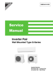
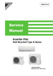
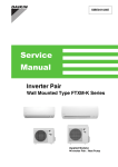
1
SiBE041401E Service Manual Inverter Pair Wall Mounted Type L-Series [Applied Models] z Inverter Pair : Heat Pump SiBE041401E Inverter Pair Wall Mounted Type L-Series zHeat Pump Indoor Unit FTXG20LV1BW FTXG20LV1BS FTXG25LV1BW FTXG25LV1BS FTXG35LV1BW FTXG35LV1BS FTXG50LV1BW FTXG50LV1BS Outdoor Unit RXG20L2V1B RXG25L2V1B RXG35L2V1B RXG50L2V1B i Table of Contents SiBE041401E 1. Safety Cautions.......................................................................................v 1.1 Warnings and Cautions Regarding Safety of Workers.............................v 1.2 Warnings and Cautions Regarding Safety of Users............................... vii 2. Used Icons ..............................................................................................x Part 1 List of Functions ................................................................ 1 1. Functions.................................................................................................2 Part 2 Specifications .................................................................... 3 1. Specifications ..........................................................................................4 Part 3 Printed Circuit Board Connector Wiring Diagram ............. 8 1. Indoor Unit...............................................................................................9 2. Outdoor Unit..........................................................................................11 2.1 20/25/35 Class .......................................................................................11 2.2 50 Class .................................................................................................13 Part 4 Function and Control........................................................ 15 1. Main Functions......................................................................................16 1.1 1.2 1.3 1.4 1.5 1.6 1.7 1.8 1.9 1.10 1.11 1.12 1.13 1.14 1.15 1.16 Temperature Control ..............................................................................16 Frequency Principle................................................................................16 Operation Starting Control......................................................................18 Airflow Direction Control.........................................................................19 Fan Speed Control for Indoor Unit .........................................................20 Program Dry Operation ..........................................................................21 Automatic Operation...............................................................................22 Thermostat Control.................................................................................23 NIGHT SET Mode ..................................................................................24 ECONO Operation .................................................................................24 2-Area INTELLIGENT EYE Operation ...................................................25 Inverter POWERFUL Operation .............................................................27 Multi-Monitor Lamp / TIMER Lamp ........................................................27 Clock Setting ..........................................................................................28 WEEKLY TIMER Operation ...................................................................29 Other Functions......................................................................................35 2. Function of Thermistor ..........................................................................36 3. Control Specification .............................................................................37 3.1 3.2 3.3 3.4 3.5 3.6 3.7 3.8 3.9 3.10 3.11 3.12 Table of Contents Mode Hierarchy ......................................................................................37 Frequency Control..................................................................................37 Controls at Mode Changing / Start-up....................................................39 Discharge Pipe Temperature Control.....................................................40 Input Current Control..............................................................................41 Freeze-up Protection Control .................................................................42 Heating Peak-cut Control .......................................................................42 Outdoor Fan Control...............................................................................43 Liquid Compression Protection Function................................................43 Defrost Control .......................................................................................44 Electronic Expansion Valve Control .......................................................45 Malfunctions ...........................................................................................48 ii SiBE041401E Part 5 Remote Controller ............................................................ 49 1. Remote controller..................................................................................50 Part 6 Service Diagnosis............................................................. 52 1. General Problem Symptoms and Check Items .....................................53 2. Troubleshooting with LED .....................................................................54 2.1 Indoor Unit..............................................................................................54 2.2 Outdoor Unit ...........................................................................................54 3. Service Diagnosis .................................................................................55 4. Troubleshooting ....................................................................................58 4.1 4.2 4.3 4.4 4.5 4.6 4.7 4.8 4.9 4.10 4.11 4.12 4.13 4.14 4.15 4.16 4.17 4.18 4.19 4.20 4.21 4.22 4.23 4.24 4.25 Error Codes and Description ..................................................................58 Indoor Unit PCB Abnormality .................................................................59 Freeze-up Protection Control / Heating Peak-cut Control ......................60 Fan Motor (DC Motor) or Related Abnormality.......................................61 Thermistor or Related Abnormality (Indoor Unit)....................................63 Front Panel Open / Close Fault..............................................................64 Refrigerant Shortage ..............................................................................65 Low-voltage Detection or Over-voltage Detection..................................67 Signal Transmission Error (Between Indoor Unit and Outdoor Unit)......69 Unspecified Voltage (Between Indoor Unit and Outdoor Unit) ...............71 Outdoor Unit PCB Abnormality...............................................................72 OL Activation (Compressor Overload) ...................................................73 Compressor Lock ...................................................................................75 DC Fan Lock ..........................................................................................76 Input Overcurrent Detection ...................................................................77 Four Way Valve Abnormality..................................................................78 Discharge Pipe Temperature Control.....................................................80 High Pressure Control in Cooling ...........................................................81 Compressor System Sensor Abnormality ..............................................82 Position Sensor Abnormality ..................................................................83 DC Voltage / Current Sensor Abnormality (20/25/35 Class Only)..........85 Thermistor or Related Abnormality (Outdoor Unit).................................86 Electrical Box Temperature Rise............................................................88 Radiation Fin Temperature Rise ............................................................89 Output Overcurrent Detection ................................................................91 5. Check ....................................................................................................93 5.1 5.2 5.3 5.4 5.5 5.6 5.7 5.8 5.9 5.10 5.11 5.12 5.13 iii Thermistor Resistance Check ................................................................93 Fan Motor Connector Output Check ......................................................94 Power Supply Waveforms Check...........................................................94 Electronic Expansion Valve Check.........................................................94 Four Way Valve Performance Check .....................................................95 Inverter Unit Refrigerant System Check.................................................95 Inverter Analyzer Check .........................................................................96 Rotation Pulse Check on the Outdoor Unit PCB ....................................97 Installation Condition Check...................................................................98 Discharge Pressure Check.....................................................................99 Outdoor Fan System Check ...................................................................99 Main Circuit Short Check......................................................................100 Power Module Check ...........................................................................101 Table of Contents SiBE041401E Part 7 Trial Operation and Field Settings................................. 103 1. Tips for Servicing ................................................................................104 1.1 Pump Down Operation .........................................................................104 1.2 Forced Cooling Operation ....................................................................104 2. Trial Operation ....................................................................................106 3. Field Settings ......................................................................................107 3.1 3.2 3.3 3.4 When 2 Units are installed in 1 Room ..................................................107 Model Type Setting ..............................................................................107 Standby Electricity Saving....................................................................108 Jumper Settings ...................................................................................109 4. Silicon Grease on Power Transistor / Diode Bridge............................110 Part 8 Appendix......................................................................... 111 1. Piping Diagrams..................................................................................112 1.1 Indoor Unit............................................................................................112 1.2 Outdoor Unit .........................................................................................112 2. Wiring Diagrams..................................................................................114 2.1 Indoor Unit............................................................................................114 2.2 Outdoor Unit .........................................................................................114 Table of Contents iv Safety Cautions SiBE041401E 1. Safety Cautions Be sure to read the following safety cautions before conducting repair work. After the repair work is complete, be sure to conduct a test operation to ensure that the equipment operates normally, and explain the cautions for operating the product to the customer. Caution Items Pictograms 1.1 The caution items are classified into Warning and Caution. The Warning items are especially important since they can lead to death or serious injury if they are not followed closely. The Caution items can also lead to serious accidents under some conditions if they are not followed. Therefore, be sure to observe all the safety caution items described below. This symbol indicates the item for which caution must be exercised. The pictogram shows the item to which attention must be paid. This symbol indicates the prohibited action. The prohibited item or action is shown in the illustration or near the symbol. This symbol indicates the action that must be taken, or the instruction. The instruction is shown in the illustration or near the symbol. Warnings and Cautions Regarding Safety of Workers Warning Do not store the equipment in a room with successive fire sources (e.g., naked flame, gas appliance, electric heater). Be sure to disconnect the power cable plug from the plug socket before disassembling the equipment for repair. Working on the equipment that is connected to the power supply may cause an electrical shock. If it is necessary to supply power to the equipment to conduct the repair or inspecting the circuits, do not touch any electrically charged sections of the equipment. If the refrigerant gas is discharged during the repair work, do not touch the discharged refrigerant gas. The refrigerant gas may cause frostbite. When disconnecting the suction or discharge pipe of the compressor at the welded section, evacuate the refrigerant gas completely at a wellventilated place first. If there is gas remaining inside the compressor, the refrigerant gas or refrigerating machine oil discharges when the pipe is disconnected, and it may cause injury. If the refrigerant gas leaks during the repair work, ventilate the area. The refrigerant gas may generate toxic gases when it contacts flames. Be sure to discharge the capacitor completely before conducting repair work. The step-up capacitor supplies high-voltage electricity to the electrical components of the outdoor unit. A charged capacitor may cause an electrical shock. v SiBE041401E Safety Cautions Warning Do not start or stop the air conditioner operation by plugging or unplugging the power cable plug. Plugging or unplugging the power cable plug to operate the equipment may cause an electrical shock or fire. Be sure to wear a safety helmet, gloves, and a safety belt when working at a high place (more than 2 m). Insufficient safety measures may cause a fall accident. In case of R-32 / R-410A refrigerant models, be sure to use pipes, flare nuts and tools for the exclusive use of the R-32 / R-410A refrigerant. The use of materials for R-22 refrigerant models may cause a serious accident such as a damage of refrigerant cycle as well as an equipment failure. Do not mix air or gas other than the specified refrigerant (R-32 / R-410A / R-22) in the refrigerant system. If air enters the refrigerating system, an excessively high pressure results, causing equipment damage and injury. Caution Do not repair the electrical components with wet hands. Working on the equipment with wet hands may cause an electrical shock. Do not clean the air conditioner by splashing water. Washing the unit with water may cause an electrical shock. Be sure to provide the earth / grounding when repairing the equipment in a humid or wet place, to avoid electrical shocks. Be sure to turn off the power switch and unplug the power cable when cleaning the equipment. The internal fan rotates at a high speed, and may cause injury. Be sure to conduct repair work with appropriate tools. The use of inappropriate tools may cause injury. Be sure to check that the refrigerating cycle section has cooled down enough before conducting repair work. Working on the unit when the refrigerating cycle section is hot may cause burns. vi Safety Cautions SiBE041401E Caution Use the welder in a well-ventilated place. Using the welder in an enclosed room may cause oxygen deficiency. 1.2 Warnings and Cautions Regarding Safety of Users Warning Do not store the equipment in a room with successive fire sources (e.g., naked flame, gas appliance, electric heater). Be sure to use parts listed in the service parts list of the applicable model and appropriate tools to conduct repair work. Never attempt to modify the equipment. The use of inappropriate parts or tools may cause an electrical shock, excessive heat generation or fire. If the power cable and lead wires have scratches or deteriorated, be sure to replace them. Damaged cable and wires may cause an electrical shock, excessive heat generation or fire. Do not use a joined power cable or extension cable, or share the same power outlet with other electrical appliances, since it may cause an electrical shock, excessive heat generation or fire. Be sure to use an exclusive power circuit for the equipment, and follow the local technical standards related to the electrical equipment, the internal wiring regulations, and the instruction manual for installation when conducting electrical work. Insufficient power circuit capacity and improper electrical work may cause an electrical shock or fire. Be sure to use the specified cable for wiring between the indoor and outdoor units. Make the connections securely and route the cable properly so that there is no force pulling the cable at the connection terminals. Improper connections may cause excessive heat generation or fire. When wiring between the indoor and outdoor units, make sure that the terminal cover does not lift off or dismount because of the cable. If the cover is not mounted properly, the terminal connection section may cause an electrical shock, excessive heat generation or fire. Do not damage or modify the power cable. Damaged or modified power cable may cause an electrical shock or fire. Placing heavy items on the power cable, and heating or pulling the power cable may damage the cable. vii SiBE041401E Safety Cautions Warning Do not mix air or gas other than the specified refrigerant (R-32 / R-410A / R-22) in the refrigerant system. If air enters the refrigerating system, an excessively high pressure results, causing equipment damage and injury. If the refrigerant gas leaks, be sure to locate the leaking point and repair it before charging the refrigerant. After charging refrigerant, make sure that there is no refrigerant leak. If the leaking point cannot be located and the repair work must be stopped, be sure to perform pump-down and close the service valve, to prevent the refrigerant gas from leaking into the room. The refrigerant gas itself is harmless, but it may generate toxic gases when it contacts flames, such as fan and other heaters, stoves and ranges. When relocating the equipment, make sure that the new installation site has sufficient strength to withstand the weight of the equipment. If the installation site does not have sufficient strength and if the installation work is not conducted securely, the equipment may fall and cause injury. Check to make sure that the power cable plug is not dirty or loose, then insert the plug into a power outlet securely. If the plug has dust or loose connection, it may cause an electrical shock or fire. Be sure to install the product correctly by using the provided standard For unitary type installation frame. only Incorrect use of the installation frame and improper installation may cause the equipment to fall, resulting in injury. Be sure to install the product securely in the installation frame mounted For unitary type on the window frame. only If the unit is not securely mounted, it may fall and cause injury. When replacing the coin battery in the remote controller, be sure to dispose of the old battery to prevent children from swallowing it. If a child swallows the coin battery, see a doctor immediately. Caution Installation of a leakage breaker is necessary in some cases depending on the conditions of the installation site, to prevent electrical shocks. Do not install the equipment in a place where there is a possibility of combustible gas leaks. If the combustible gas leaks and remains around the unit, it may cause a fire. viii Safety Cautions SiBE041401E Caution Check to see if the parts and wires are mounted and connected properly, and if the connections at the soldered or crimped terminals are secure. Improper installation and connections may cause excessive heat generation, fire or an electrical shock. If the installation platform or frame has corroded, replace it. Corroded installation platform or frame may cause the unit to fall, resulting in injury. Check the earth / grounding, and repair it if the equipment is not properly earthed / grounded. Improper earth / grounding may cause an electrical shock. Be sure to measure the insulation resistance after the repair, and make sure that the resistance is 1 MΩ or higher. Faulty insulation may cause an electrical shock. Be sure to check the drainage of the indoor unit after the repair. Faulty drainage may cause the water to enter the room and wet the furniture and floor. Do not tilt the unit when removing it. The water inside the unit may spill and wet the furniture and floor. Be sure to install the packing and seal on the installation frame properly. For unitary type If the packing and seal are not installed properly, water may enter the room and only wet the furniture and floor. ix SiBE041401E Used Icons 2. Used Icons The following icons are used to attract the attention of the reader to specific information. Icon Type of Information Warning Description Caution A Caution is used when there is danger that the reader, through incorrect manipulation, may damage equipment, loose data, get an unexpected result or has to restart (part of) a procedure. Note A Note provides information that is not indispensable, but may nevertheless be valuable to the reader, such as tips and tricks. Reference A Reference guides the reader to other places in this binder or in this manual, where he/she will find additional information on a specific topic. A Warning is used when there is danger of personal injury. Warning Caution Note: x SiBE041401E Part 1 List of Functions 1. Functions.................................................................................................2 1 List of Functions SiBE041401E Functions Functions Basic Function Inverter (with inverter power control) Comfortable Airflow Comfort Control Operation Lifestyle Convenience Functions Health & Clean Air-purifying filter — z Photocatalytic deodorizing filter — Standby electricity saving z Oval scroll compressor — Air-purifying filter with photocatalytic deodorizing function — Titanium apatite photocatalytic air-purifying filter z z PAM control Compressor z Category FTXG20/25/35/50LV1BW(S) RXG20/25/35/50L2V1B Category FTXG20/25/35/50LV1BW(S) RXG20/25/35/50L2V1B 1. Functions Swing compressor z Rotary compressor — Reluctance DC motor z Air filter (prefilter) Power-airflow flap — Wipe-clean flat panel z Power-airflow dual flaps z Washable grille — Power-airflow diffuser — MOLD PROOF operation — Wide-angle louvers z Heating dry operation — Auto-swing (up and down) z Good-sleep cooling operation — Auto-swing (right and left) z WEEKLY TIMER operation z 3-D airflow z 24-hour ON/OFF timer z COMFORT AIRFLOW operation z NIGHT SET mode z Auto fan speed z Auto-restart (after power failure) z Indoor unit quiet operation z NIGHT QUIET mode (automatic) Timer Worry Free (Reliability & Durability) Self-diagnosis (digital, led) display z — Wiring error check function — OUTDOOR UNIT QUIET operation (manual) z Anti-corrosion treatment of outdoor heat exchanger z INTELLIGENT EYE operation z Flexibility Multi-split / split type compatible indoor unit z Flexible power supply correspondence — Quick warming function (preheating operation) z Hot-start function z Chargeless High ceiling application — 10 m Automatic defrosting z Either side drain (right or left) z Automatic operation z Power selection — Program dry operation z 5-room centralized controller (option) z Fan only z New POWERFUL operation (non-inverter) — Remote control adaptor (normal open pulse contact) (option) z Remote control adaptor (normal open contact) (option) z DIII-NET compatible (adaptor) (option) z Inverter POWERFUL operation z Priority-room setting — COOL / HEAT mode lock — HOME LEAVE operation — ECONO operation z Indoor unit ON/OFF button z Signal receiving sign z Multi-colored indicator lamp (multi-monitor lamp) z Monitor brightness setting z R/C with back light z Temperature display — Remote Control Remote Controller Wireless z Wired (option) — Note: z : Available — : Not available List of Functions 2 SiBE041401E Part 2 Specifications 1. Specifications ..........................................................................................4 3 Specifications SiBE041401E Specifications 1. Specifications 50 Hz, 220 - 230 - 240 V Indoor Unit Model FTXG20LV1BW RXG20L2V1B Outdoor Unit Capacity Rated (Min. ~ Max.) Running Current (Rated) Power Consumption Rated (Min. ~ Max.) Power Factor (Rated) EER (Cooling) / COP (Heating) Rated (Min. ~ Max.) Liquid Piping Connections Gas Drain Heat Insulation Max. Interunit Piping Length Max. Interunit Height Difference Chargeless Amount of Additional Charge of Refrigerant Indoor Unit Front Panel Color H M Airflow Rate L SL Type Fan Motor Output Speed Air Direction Control Air Filter Running Current (Rated) Power Consumption (Rated) Power Factor (Rated) Temperature Control Dimensions (H × W × D) Packaged Dimensions (H × W × D) Weight (Mass) Gross Weight (Gross Mass) Sound Pressure H / M / L / SL Level Sound Power Level Outdoor Unit Casing Color Type Compressor Model Motor Output Type Refrigerant Oil Charge Type Refrigerant Charge H Airflow Rate SL Type Fan Motor Output Running Current (Rated) Power Consumption (Rated) Power Factor (Rated) Starting Current Dimensions (H × W × D) Packaged Dimensions (H × W × D) Weight (Mass) Gross Weight (Gross Mass) Sound Pressure H / SL Level Sound Power Level Drawing No. Note: Cooling 2.3 (1.3 ~ 2.8) 7,800 (4,400 ~ 9,500) 1,980 (1,120 ~ 2,410) 2.8 - 2.7 - 2.6 Heating 2.5 (1.3 ~ 4.3) 8,500 (4,400 ~ 14,600) 2,150 (1,120 ~ 3,700) 2.8 - 2.7 - 2.6 W 501 (320 ~ 760) % 81.3 - 80.7 - 80.2 W/W 4.59 (4.06 ~ 3.68) kW Btu/h kcal/h A Cooling 2.3 (1.3 ~ 2.8) 7,800 (4,400 ~ 9,500) 1,980 (1,120 ~ 2,410) 2.8 - 2.7 - 2.6 Heating 2.5 (1.3 ~ 4.3) 8,500 (4,400 ~ 14,600) 2,150 (1,120 ~ 3,700) 2.8 - 2.7 - 2.6 500 (310 ~ 1,120) 501 (320 ~ 760) 500 (310 ~ 1,120) 81.1 - 80.5 - 80.1 81.3 - 80.7 - 80.2 81.1 - 80.5 - 80.1 5.00 (4.19 ~ 3.84) 4.59 (4.06 ~ 3.68) 5.00 (4.19 ~ 3.84) mm mm mm φ 6.4 φ 9.5 φ 18.0 φ 6.4 φ 9.5 φ 18.0 m m m Both Liquid and Gas Pipes 20 15 10 Both Liquid and Gas Pipes 20 15 10 g/m m³/min (cfm) W Steps A W % mm mm kg kg 20 20 FTXG20LV1BW White FTXG20LV1BS Silver 8.9 (313) 6.6 (234) 4.4 (155) 2.6 (91) dB(A) 38 / 32 / 25 / 19 dB 54 W L kg m³/min (cfm) W A W % A mm mm kg kg 10.2 (361) 8.4 (298) 6.3 (223) 3.8 (133) 8.9 (313) 6.6 (234) 4.4 (155) 2.6 (91) Cross Flow Fan 29 5 Steps, Quiet, Auto Right, Left, Horizontal, Downwards Removable / Washable / Mildew Proof 0.12 - 0.12 - 0.12 0.15 - 0.15 - 0.15 23 - 23 - 23 31 - 31 - 31 87.1 - 83.3 - 79.9 93.9 - 89.9 - 86.1 Microcomputer Control 303 × 998 × 212 322 × 1,101 × 389 12 16 dB(A) 46 / 43 dB 61 40 / 34 / 28 / 19 38 / 32 / 25 / 19 40 / 34 / 28 / 19 54 56 RXG20L2V1B Ivory White Hermetically Sealed Swing Type 1YC23APXD 600 FVC50K 0.375 R-410A 1.05 34.5 (1,218) 31.1 (1,098) 31.0 (1,094) 26.4 (932) Propeller 23 2.68 - 2.58 - 2.48 2.65 - 2.55 - 2.45 478 - 478 - 478 472 - 472 - 472 81.1 - 80.6 - 80.3 81.0 - 80.5 - 80.3 2.8 550 × 765 × 285 612 × 906 × 402 35 38 47 / 44 46 / 43 62 61 3D086752 47 / 44 62 3D086756 The data are based on the conditions shown in the table below. Heating Indoor ; 20°CDB Outdoor ; 7°CDB / 6°CWB 10.2 (361) 8.4 (298) 6.3 (223) 3.8 (133) Cross Flow Fan 29 5 Steps, Quiet, Auto Right, Left, Horizontal, Downwards Removable / Washable / Mildew Proof 0.12 - 0.12 - 0.12 0.15 - 0.15 - 0.15 23 - 23 - 23 31 - 31 - 31 87.1 - 83.3 - 79.9 93.9 - 89.9 - 86.1 Microcomputer Control 303 × 998 × 212 322 × 1,101 × 389 12 16 56 RXG20L2V1B Ivory White Hermetically Sealed Swing Type 1YC23APXD 600 FVC50K 0.375 R-410A 1.05 34.5 (1,218) 31.1 (1,098) 31.0 (1,094) 26.4 (932) Propeller 23 2.68 - 2.58 - 2.48 2.65 - 2.55 - 2.45 478 - 478 - 478 472 - 472 - 472 81.1 - 80.6 - 80.3 81.0 - 80.5 - 80.3 2.8 550 × 765 × 285 612 × 906 × 402 35 38 Cooling Indoor ; 27°CDB / 19°CWB Outdoor ; 35°CDB / 24°CWB Specifications FTXG20LV1BS RXG20L2V1B Piping Length 5m Conversion Formulae kcal/h = kW × 860 Btu/h = kW × 3412 cfm = m³/min × 35.3 4 Specifications SiBE041401E 50 Hz, 220 - 230 - 240 V Indoor Unit Model FTXG25LV1BW RXG25L2V1B Outdoor Unit Capacity Rated (Min. ~ Max.) Running Current (Rated) Power Consumption Rated (Min. ~ Max.) Power Factor (Rated) EER (Cooling) / COP (Heating) Rated (Min. ~ Max.) Liquid Piping Connections Gas Drain Heat Insulation Max. Interunit Piping Length Max. Interunit Height Difference Chargeless Amount of Additional Charge of Refrigerant Indoor Unit Front Panel Color H M Airflow Rate L SL Type Fan Motor Output Speed Air Direction Control Air Filter Running Current (Rated) Power Consumption (Rated) Power Factor (Rated) Temperature Control Dimensions (H × W × D) Packaged Dimensions (H × W × D) Weight (Mass) Gross Weight (Gross Mass) Sound Pressure H / M / L / SL Level Sound Power Level Outdoor Unit Casing Color Type Compressor Model Motor Output Type Refrigerant Oil Charge Type Refrigerant Charge H Airflow Rate SL Type Fan Motor Output Running Current (Rated) Power Consumption (Rated) Power Factor (Rated) Starting Current Dimensions (H × W × D) Packaged Dimensions (H × W × D) Weight (Mass) Gross Weight (Gross Mass) Sound Pressure H / SL Level Sound Power Level Drawing No. Note: Cooling 2.4 (1.3 ~ 3.0) 8,200 (4,400 ~ 10,200) 2,060 (1,120 ~ 2,580) 2.9 - 2.8 - 2.7 Heating 3.4 (1.3 ~ 4.5) 11,600 (4,400 ~ 15,400) 2,920 (1,120 ~ 3,870) 4.4 - 4.2 - 4.0 W 523 (320 ~ 820) % 82.0 - 81.2 - 80.7 W/W 4.59 (4.06 ~ 3.66) kW Btu/h kcal/h A Cooling 2.4 (1.3 ~ 3.0) 8,200 (4,400 ~ 10,200) 2,060 (1,120 ~ 2,580) 2.9 - 2.8 - 2.7 Heating 3.4 (1.3 ~ 4.5) 11,600 (4,400 ~ 15,400) 2,920 (1,120 ~ 3,870) 4.4 - 4.2 - 4.0 769 (310 ~ 1,320) 523 (320 ~ 820) 769 (310 ~ 1,320) 79.4 - 79.6 - 80.1 82.0 - 81.2 - 80.7 79.4 - 79.6 - 80.1 4.42 (4.19 ~ 3.41) 4.59 (4.06 ~ 3.66) 4.42 (4.19 ~ 3.41) mm mm mm φ 6.4 φ 9.5 φ 18.0 φ 6.4 φ 9.5 φ 18.0 m m m Both Liquid and Gas Pipes 20 15 10 Both Liquid and Gas Pipes 20 15 10 g/m m³/min (cfm) W Steps A W % mm mm kg kg 20 20 FTXG25LV1BW White FTXG25LV1BS Silver 8.9 (313) 6.6 (234) 4.4 (155) 2.6 (91) dB(A) 38 / 32 / 25 / 19 dB 54 W L kg m³/min (cfm) W A W % A mm mm kg kg 11.0 (388) 8.6 (303) 6.3 (223) 3.8 (133) 8.9 (313) 6.6 (234) 4.4 (155) 2.6 (91) Cross Flow Fan 29 5 Steps, Quiet, Auto Right, Left, Horizontal, Downwards Removable / Washable / Mildew Proof 0.12 - 0.12 - 0.12 0.16 - 0.16 - 0.16 23 - 23 - 23 33 - 33 - 33 87.1 - 83.3 - 79.9 93.8 - 89.6 - 85.9 Microcomputer Control 303 × 998 × 212 322 × 1,101× 389 12 16 dB(A) 46 / 43 dB 61 41 / 34 / 28 / 19 38 / 32 / 25 / 19 41 / 34 / 28 / 19 54 56 RXG25L2V1B Ivory White Hermetically Sealed Swing Type 1YC23APXD 600 FVC50K 0.375 R-410A 1.05 34.5 (1,218) 31.1 (1,098) 31.0 (1,094) 26.4 (932) Propeller 23 2.78 - 2.68 - 2.58 4.24 - 4.04 - 3.84 500 - 500 - 500 736 - 736 - 736 81.8 - 81.1 - 80.7 78.9 - 79.2 - 79.8 4.4 550 × 765 × 285 612 × 906 × 402 35 38 47 / 44 46 / 43 62 61 3D086753 47 / 44 62 3D086757 The data are based on the conditions shown in the table below. Heating Indoor ; 20°CDB Outdoor ; 7°CDB / 6°CWB 11.0 (388) 8.6 (303) 6.3 (223) 3.8 (133) Cross Flow Fan 29 5 Steps, Quiet, Auto Right, Left, Horizontal, Downwards Removable / Washable / Mildew Proof 0.12 - 0.12 - 0.12 0.16 - 0.16 - 0.16 23 - 23 - 23 33 - 33 - 33 87.1 - 83.3 - 79.9 93.8 - 89.6 - 85.9 Microcomputer Control 303 × 998 × 212 322 × 1,101× 389 12 16 56 RXG25L2V1B Ivory White Hermetically Sealed Swing Type 1YC23APXD 600 FVC50K 0.375 R-410A 1.05 34.5 (1,218) 31.1 (1,098) 31.0 (1,094) 26.4 (932) Propeller 23 2.78 - 2.68 - 2.58 4.24 - 4.04 - 3.84 500 - 500 - 500 736 - 736 - 736 81.8 - 81.1 - 80.7 78.9 - 79.2 - 79.8 4.4 550 × 765 × 285 612 × 906 × 402 35 38 Cooling Indoor ; 27°CDB / 19°CWB Outdoor ; 35°CDB / 24°CWB 5 FTXG25LV1BS RXG25L2V1B Piping Length 5m Conversion Formulae kcal/h = kW × 860 Btu/h = kW × 3412 cfm = m³/min × 35.3 Specifications SiBE041401E Specifications 50 Hz, 220 - 230 - 240 V Indoor Unit Model FTXG35LV1BW RXG35L2V1B Outdoor Unit Capacity Rated (Min. ~ Max.) Running Current (Rated) Power Consumption Rated (Min. ~ Max.) Power Factor (Rated) EER (Cooling) / COP (Heating) Rated (Min. ~ Max.) Liquid Piping Connections Gas Drain Heat Insulation Max. Interunit Piping Length Max. Interunit Height Difference Chargeless Amount of Additional Charge of Refrigerant Indoor Unit Front Panel Color H M Airflow Rate L SL Type Fan Motor Output Speed Air Direction Control Air Filter Running Current (Rated) Power Consumption (Rated) Power Factor (Rated) Temperature Control Dimensions (H × W × D) Packaged Dimensions (H × W × D) Weight (Mass) Gross Weight (Gross Mass) Sound Pressure H / M / L / SL Level Sound Power Level Outdoor Unit Casing Color Type Compressor Model Motor Output Type Refrigerant Oil Charge Type Refrigerant Charge H Airflow Rate SL Type Fan Motor Output Running Current (Rated) Power Consumption (Rated) Power Factor (Rated) Starting Current Dimensions (H × W × D) Packaged Dimensions (H × W × D) Weight (Mass) Gross Weight (Gross Mass) Sound Pressure H / SL Level Sound Power Level Drawing No. Note: kW Btu/h kcal/h A Cooling 3.5 (1.4 ~ 3.8) 11,900 (4,800 ~ 13,000) 3,010 (1,200 ~ 3,270) 5.0 - 4.8 - 4.6 Heating 4.0 (1.4 ~ 5.0) 13,600 (4,800 ~ 17,100) 3,440 (1,200 ~ 4,300) 5.5 - 5.3 - 5.1 Cooling 3.5 (1.4 ~ 3.8) 11,900 (4,800 ~ 13,000) 3,010 (1,200 ~ 3,270) 5.0 - 4.8 - 4.6 Heating 4.0 (1.4 ~ 5.0) 13,600 (4,800 ~ 17,100) 3,440 (1,200 ~ 4,300) 5.5 - 5.3 - 5.1 W 882 (350 ~ 1,190) 985 (320 ~ 1,490) 882 (350 ~ 1,190) 985 (320 ~ 1,490) % 80.2 - 79.9 - 79.9 81.1 - 80.8 - 80.5 80.2 - 79.9 - 79.9 81.1 - 80.8 - 80.5 W/W 3.97 (4.06 ~ 3.19) 4.06 (4.38 ~ 3.36) 3.97 (4.06 ~ 3.19) 4.06 (4.38 ~ 3.36) mm mm mm φ 6.4 φ 9.5 φ 18.0 φ 6.4 φ 9.5 φ 18.0 m m m Both Liquid and Gas Pipes 20 15 10 Both Liquid and Gas Pipes 20 15 10 g/m m³/min (cfm) W Steps A W % mm mm kg kg 20 20 FTXG35LV1BW White FTXG35LV1BS Silver 10.9 (385) 7.8 (276) 4.8 (168) 2.9 (102) dB(A) 45 / 34 / 26 / 20 dB 59 W L kg m³/min (cfm) W A W % A mm mm kg kg 12.4 (438) 9.6 (340) 6.9 (245) 4.1 (144) 10.9 (385) 7.8 (276) 4.8 (168) 2.9 (102) Cross Flow Fan 29 5 Steps, Quiet, Auto Right, Left, Horizontal, Downwards Removable / Washable / Mildew Proof 0.16 - 0.16 - 0.16 0.21 - 0.21 - 0.21 33 - 33 - 33 42 - 42 - 42 93.8 - 89.6 - 85.9 90.9 - 87.0 - 83.3 Microcomputer Control 303 × 998 × 212 322 × 1,101 × 389 12 16 dB(A) 48 / 44 dB 63 45 / 37 / 29 / 20 45 / 34 / 26 / 20 45 / 37 / 29 / 20 59 59 RXG35L2V1B Ivory White Hermetically Sealed Swing Type 1YC23APXD 600 FVC50K 0.375 R-410A 1.05 37.0 (1,306) 31.1 (1,098) 31.0 (1,094) 26.4 (932) Propeller 23 4.84 - 4.64 - 4.44 5.29 - 5.09 - 4.89 849 - 849 - 849 943 - 943 - 943 79.7 - 79.6 - 79.7 81.0 - 80.6 - 80.4 5.5 550 × 765 × 285 612 × 906 × 402 35 38 48 / 45 48 / 44 63 63 3D086754 48 / 45 63 C: 3D086758 The data are based on the conditions shown in the table below. Heating Indoor ; 20°CDB Outdoor ; 7°CDB / 6°CWB 12.4 (438) 9.6 (340) 6.9 (245) 4.1 (144) Cross Flow Fan 29 5 Steps, Quiet, Auto Right, Left, Horizontal, Downwards Removable / Washable / Mildew Proof 0.16 - 0.16 - 0.16 0.21 - 0.21 - 0.21 33 - 33 - 33 42 - 42 - 42 93.8 - 89.6 - 85.9 90.9 - 87.0 - 83.3 Microcomputer Control 303 × 998 × 212 322 × 1,101 × 389 12 16 59 RXG35L2V1B Ivory White Hermetically Sealed Swing Type 1YC23APXD 600 FVC50K 0.375 R-410A 1.05 37.0 (1,306) 31.1 (1,098) 31.0 (1,094) 26.4 (932) Propeller 23 4.84 - 4.64 - 4.44 5.29 - 5.09 - 4.89 849 - 849 - 849 943 - 943 - 943 79.7 - 79.6 - 79.7 81.0 - 80.6 - 80.4 5.5 550 × 765 × 285 612 × 906 × 402 35 38 Cooling Indoor ; 27°CDB / 19°CWB Outdoor ; 35°CDB / 24°CWB Specifications FTXG35LV1BS RXG35L2V1B Piping Length 5m Conversion Formulae kcal/h = kW × 860 Btu/h = kW × 3412 cfm = m³/min × 35.3 6 Specifications SiBE041401E 50 Hz, 220 - 230 - 240 V Indoor Unit Model FTXG50LV1BW RXG50L2V1B Outdoor Unit Capacity Rated (Min. ~ Max.) Running Current (Rated) Power Consumption Rated (Min. ~ Max.) Power Factor (Rated) EER (Cooling) / COP (Heating) Rated (Min. ~ Max.) Liquid Piping Connections Gas Drain Heat Insulation Max. Interunit Piping Length Max. Interunit Height Difference Chargeless Amount of Additional Charge of Refrigerant Indoor Unit Front Panel Color H M Airflow Rate L SL Type Fan Motor Output Speed Air Direction Control Air Filter Running Current (Rated) Power Consumption (Rated) Power Factor (Rated) Temperature Control Dimensions (H × W × D) Packaged Dimensions (H × W × D) Weight (Mass) Gross Weight (Gross Mass) Sound Pressure H / M / L / SL Level Sound Power Level Outdoor Unit Casing Color Type Compressor Model Motor Output Type Refrigerant Oil Charge Type Refrigerant Charge H Airflow Rate SL Type Fan Motor Output Running Current (Rated) Power Consumption (Rated) Power Factor (Rated) Starting Current Dimensions (H × W × D) Packaged Dimensions (H × W × D) Weight (Mass) Gross Weight (Gross Mass) Sound Pressure H / SL Level Sound Power Level Drawing No. Note: kW Btu/h kcal/h A Cooling 4.8 (1.7 ~ 5.3) 16,400 (5,800 ~ 18,100) 4,130 (1,460 ~ 4,560) 6.5 - 6.2 - 5.9 Heating 5.8 (1.7 ~ 6.5) 19,800 (5,800 ~ 22,200) 4,990 (1,460 ~ 5,590) 7.4 - 7.1 - 6.8 Cooling 4.8 (1.7 ~ 5.3) 16,400 (5,800 ~ 18,100) 4,130 (1,460 ~ 4,560) 6.5 - 6.2 - 5.9 Heating 5.8 (1.7 ~ 6.5) 19,800 (5,800 ~ 22,200) 4,990 (1,460 ~ 5,590) 7.4 - 7.1 - 6.8 W 1,360 (370 ~ 1,880) 1,589 (310 ~ 2,490) 1,360 (370 ~ 1,880) 1,589 (310 ~ 2,490) % 95.1 - 95.4 - 96.0 97.6 - 97.3 - 97.4 95.1 - 95.4 - 96.0 97.6 - 97.3 - 97.4 W/W 3.53 (4.59 ~ 2.82) 3.65 (5.48 ~ 2.61) 3.53 (4.59 ~ 2.82) 3.65 (5.48 ~ 2.61) mm mm mm φ 6.4 φ 12.7 φ 18.0 φ 6.4 φ 12.7 φ 18.0 m m m Both Liquid and Gas Pipes 30 20 10 Both Liquid and Gas Pipes 30 20 10 g/m m³/min (cfm) W Steps A W % mm mm kg kg 20 20 FTXG50LV1BW White FTXG50LV1BS Silver 10.9 (385) 8.9 (313) 6.8 (239) 3.6 (128) dB(A) 46 / 40 / 35 / 32 dB 60 W L kg m³/min (cfm) W A W % A mm mm kg kg 12.6 (446) 10.5 (372) 8.1 (284) 5.0 (176) 10.9 (385) 8.9 (313) 6.8 (239) 3.6 (128) Cross Flow Fan 29 5 Steps, Quiet, Auto Right, Left, Horizontal, Downwards Removable / Washable / Mildew Proof 0.16 - 0.16 - 0.16 0.21 - 0.21 - 0.21 33 - 33 - 33 43 - 43 - 43 93.8 - 89.6 - 85.9 93.1 - 89.0 - 85.3 Microcomputer Control 303 × 998 × 212 322 × 1,101 × 389 12 16 dB(A) 48 / 44 dB 63 47 / 41 / 35 / 32 46 / 40 / 35 / 32 60 RXG50L2V1B Ivory White Hermetically Sealed Swing Type 2YC36GXD 1,100 FVC50K 0.395 R-410A 1.60 49.8 (1,758) 44.8 (1,581) 42.6 (1,504) 38.3 (1,352) Propeller 53 6.34 - 6.04 - 5.74 7.19 - 6.89 - 6.59 1,327 - 1,327 - 1,327 1,546 - 1,546 - 1,546 95.1 - 95.5 - 96.3 97.7 - 97.6 - 97.7 7.4 735 × 825 × 300 797 × 992 × 437 48 52 48 / 44 63 63 3D086755 47 / 41 / 35 / 32 60 48 / 44 48 / 44 63 C: 3D086759 The data are based on the conditions shown in the table below. Heating Indoor ; 20°CDB Outdoor ; 7°CDB / 6°CWB 12.6 (446) 10.5 (372) 8.1 (284) 5.0 (176) Cross Flow Fan 29 5 Steps, Quiet, Auto Right, Left, Horizontal, Downwards Removable / Washable / Mildew Proof 0.16 - 0.16 - 0.16 0.21 - 0.21 - 0.21 33 - 33 - 33 43 - 43 - 43 93.8 - 89.6 - 85.9 93.1 - 89.0 - 85.3 Microcomputer Control 303 × 998 × 212 322 × 1,101 × 389 12 16 60 RXG50L2V1B Ivory White Hermetically Sealed Swing Type 2YC36GXD 1,100 FVC50K 0.395 R-410A 1.60 49.8 (1,758) 44.8 (1,581) 42.6 (1,504) 38.3 (1,352) Propeller 53 6.34 - 6.04 - 5.74 7.19 - 6.89 - 6.59 1,327 - 1,327 - 1,327 1,546 - 1,546 - 1,546 95.1 - 95.5 - 96.3 97.7 - 97.6 - 97.7 7.4 735 × 825 × 300 797 × 992 × 437 48 52 Cooling Indoor ; 27°CDB / 19°CWB Outdoor ; 35°CDB / 24°CWB 7 FTXG50LV1BS RXG50L2V1B Piping Length 5m Conversion Formulae kcal/h = kW × 860 Btu/h = kW × 3412 cfm = m³/min × 35.3 Specifications SiBE041401E Part 3 Printed Circuit Board Connector Wiring Diagram 1. Indoor Unit...............................................................................................9 2. Outdoor Unit..........................................................................................11 2.1 20/25/35 Class .......................................................................................11 2.2 50 Class .................................................................................................13 Printed Circuit Board Connector Wiring Diagram 8 Indoor Unit SiBE041401E 1. Indoor Unit Control PCB (A1P) 1) S21 2) S25 3) S32 4) S41 5) S42 6) S46 7) S200 8) H1, H2, H3, 9) FG 10) JB JC 11) LED A 12) F1U, F2U 13) V1 H1 FG H2 Connector for centralized control (HA) Connector for INTELLIGENT EYE sensor PCB Indoor heat exchanger thermistor Connector for swing motors Connector for reduction motor (front panel mechanism) and limit switch Connector for signal receiver / display PCB Connector for fan motor Connector for terminal board (indoor - outdoor transmission) Connector for terminal board (frame ground) Fan speed setting when compressor stops for thermostat OFF Power failure recovery function (auto-restart) ∗ Refer to page 109 for detail. LED for service monitor (green) Fuse (3.15 A, 250 V) Varistor H3 F1U V1 S32 S41 S200 S42 JB JC F2U S21 LED A S25 S46 2P357399-1 Caution 9 Replace the PCB if you accidentally cut the jumpers other than JB and JC. Jumpers are necessary for electronic circuit. Improper operation may occur if you cut any of them. Printed Circuit Board Connector Wiring Diagram SiBE041401E Signal Receiver / Display PCB (A2P) Indoor Unit 1) S51 2) S52 3) S1W 4) H1P 5) H2P 6) JA Connector for control PCB Connector for room temperature thermistor Forced cooling operation ON/OFF button ∗ Refer to page 104 for detail. LED for operation (multi-color) LED for INTELLIGENT EYE (green) Address setting jumper ∗ Refer to page 107 for detail. H1P H2P S51 S52 JA S1W Caution INTELLIGENT EYE Sensor PCB (A3P) 3P357402-1 Replace the PCB if you accidentally cut the jumpers other than JA. Jumpers are necessary for electronic circuit. Improper operation may occur if you cut any of them. 1) S36 Connector for control PCB S36 3E860004-1 Printed Circuit Board Connector Wiring Diagram 10 Outdoor Unit SiBE041401E 2. Outdoor Unit 2.1 20/25/35 Class Main PCB (PCB2) 1) 2) 3) 4) 5) 6) 7) S10 S20 S40 S50 S70 S80 S90 8) S100 9) HL3, HN3 10) HR2 11) U, V, W 12) FU2 13) LED A 14) V1 15) J5 Connector for filter PCB Connector for electronic expansion valve coil Connector for overload protector Connector for magnetic relay Connector for fan motor Connector for four way valve coil Connector for thermistors (outdoor temperature, outdoor heat exchanger, discharge pipe) Connector for forced operation button PCB Connector for filter PCB Connector for reactor Connector for compressor Fuse (3.15 A, 250 V) LED for service monitor (green) Varistor Jumper for improvement of defrost performance ∗ Refer to page 109 for detail. U V W S10 J5 S90 LED A S70 S40 HR2 S20 S80 HL3 V1 HN3 FU2 Caution 11 S100 S50 2P358715-2 Replace the PCB if you accidentally cut the jumpers other than J5. Jumpers are necessary for electronic circuit. Improper operation may occur if you cut any of them. Printed Circuit Board Connector Wiring Diagram SiBE041401E Outdoor Unit Filter PCB (PCB1) 1) 2) 3) 4) 5) 6) 7) 8) S11 AC1, AC2, S E1, E2 HL2, HN2 HR1 FU1 FU3 V2, V3 Connector for main PCB Connector for terminal board Terminal for earth wire Connector for main PCB Connector for reactor Fuse (3.15 A, 250 V) Fuse (20 A, 250 V) Varistor HR1 E1, E2 HN2 AC2 V2 AC1 V3 S11 FU3 S FU1 HL2 to S50 (on main PCB) Forced Operation Button PCB (PCB3) 1) S110 2) SW1 3P254234-1 Connector for main PCB Forced cooling operation ON/OFF button ∗ Refer to page 104 for detail. SW1 S110 3P255755-1 Printed Circuit Board Connector Wiring Diagram 12 Outdoor Unit 2.2 SiBE041401E 50 Class Main PCB (PCB2) 1) 2) 3) 4) 5) 6) 7) 8) S10 S12 S20 S40 S50 S70 S80 S90 9) HL3, HN3 10) U, V, W 11) FU2 12) LED A 13) V1 14) J8 S80 Connector for S11 on filter PCB Connector for HL4, HN4 on filter PCB Connector for electronic expansion valve coil Connector for overload protector Connector for magnetic relay Connector for fan motor Connector for four way valve coil Connector for thermistors (outdoor temperature, outdoor heat exchanger, discharge pipe) Connector for HL2, HN2 on filter PCB Terminal for compressor Fuse (3.15 A, 250 V) LED for service monitor (green) Varistor Jumper for improvement of defrost performance ∗ Refer to page 109 for detail. S70 FU2 S20 S40 S90 S50 S10 S12 LED A V1 J8 U, V, W HN3 Caution 13 HL3 2P358716-1 Replace the PCB if you accidentally cut the jumpers other than J8. Jumpers are necessary for electronic circuit. Improper operation may occur if you cut any of them. Printed Circuit Board Connector Wiring Diagram SiBE041401E Outdoor Unit Filter PCB (PCB1) 1) 2) 3) 4) 5) 6) 7) 8) 9) S11 HL1, HN1, S E1, E2 HL2, HN2 HL4, HN4 FU1 FU3 V2, V3 SW1 Connector for S10 on main PCB Connector for terminal board Terminal for earth wire Connector for HL3, HN3 on main PCB Connector for S12 on main PCB Fuse (3.15 A, 250 V) Fuse (30 A, 250 V) Varistor Forced cooling operation ON/OFF button ∗ Refer to page 104 for detail. FU3 V2 V3 S HL1 HN1 SW1 FU1 HN4, HL4 to S50 (on main PCB) HN2 HL2 E1, E2 S11 3P273862-4 Printed Circuit Board Connector Wiring Diagram 14 SiBE041401E Part 4 Function and Control 1. Main Functions......................................................................................16 1.1 1.2 1.3 1.4 1.5 1.6 1.7 1.8 1.9 1.10 1.11 1.12 1.13 1.14 1.15 1.16 Temperature Control ..............................................................................16 Frequency Principle................................................................................16 Operation Starting Control......................................................................18 Airflow Direction Control.........................................................................19 Fan Speed Control for Indoor Unit .........................................................20 Program Dry Operation ..........................................................................21 Automatic Operation...............................................................................22 Thermostat Control.................................................................................23 NIGHT SET Mode ..................................................................................24 ECONO Operation .................................................................................24 2-Area INTELLIGENT EYE Operation ...................................................25 Inverter POWERFUL Operation .............................................................27 Multi-Monitor Lamp / TIMER Lamp ........................................................27 Clock Setting ..........................................................................................28 WEEKLY TIMER Operation ...................................................................29 Other Functions......................................................................................35 2. Function of Thermistor ..........................................................................36 3. Control Specification .............................................................................37 3.1 3.2 3.3 3.4 3.5 3.6 3.7 3.8 3.9 3.10 3.11 3.12 15 Mode Hierarchy ......................................................................................37 Frequency Control..................................................................................37 Controls at Mode Changing / Start-up....................................................39 Discharge Pipe Temperature Control.....................................................40 Input Current Control..............................................................................41 Freeze-up Protection Control .................................................................42 Heating Peak-cut Control .......................................................................42 Outdoor Fan Control...............................................................................43 Liquid Compression Protection Function................................................43 Defrost Control .......................................................................................44 Electronic Expansion Valve Control .......................................................45 Malfunctions ...........................................................................................48 Function and Control SiBE041401E Main Functions 1. Main Functions 1.1 Temperature Control Definitions of Temperatures The definitions of temperatures are classified as following. Room temperature: temperature of lower part of the room Set temperature: temperature set by remote controller Room thermistor temperature: temperature detected by room temperature thermistor Target temperature: temperature determined by microcomputer Target temperature Room thermistor temperature Set temperature Room temperature (R12321) Temperature Control 1.2 The temperature of the room is detected by the room temperature thermistor. However, there is a difference between the temperature detected by room temperature thermistor and the temperature of lower part of the room, depending on the type of the indoor unit or installation condition. Practically, the temperature control is done by the target temperature appropriately adjusted for the indoor unit and the temperature detected by room temperature thermistor. Frequency Principle Control Parameters The frequency of the compressor is controlled by the following 2 parameters: The load condition of the operating indoor unit The difference between the room thermistor temperature and the target temperature The target frequency is adapted by additional parameters in the following cases: Frequency restrictions Initial settings Forced cooling operation Inverter Principle To regulate the capacity, a frequency control is needed. The inverter makes it possible to control the rotation speed of the compressor. The following table explains the inverter principle: Phase 1 2 Function and Control Description The supplied AC power source is converted into the DC power source for the present. The DC power source is reconverted into the three phase AC power source with variable frequency. When the frequency increases, the rotation speed of the compressor increases resulting in an increase of refrigerant circulation. This leads to a larger amount of heat exchange per unit. When the frequency decreases, the rotation speed of the compressor decreases resulting in a decrease of refrigerant circulation. This leads to a smaller amount of heat exchange per unit. 16 Main Functions SiBE041401E The following drawing shows a schematic view of the inverter principle: Refrigerant circulation rate (high) AC power Amount of heat exchanged air (small) DC power high speed Amount of heat exchanged air (large) high f low f low speed 50 Hz freq= constant 60 Hz freq=variable Amount of heat exchanged air (large) Amount of heat exchanged air (small) capacity= variable Refrigerant circulation rate (low) (R2812) Inverter Features The inverter provides the following features: The regulating capacity can be changed according to the changes in the outdoor temperature and cooling / heating load. Quick heating and quick cooling The rotation speed of the compressor is increased when starting the heating (or cooling). This enables to reach the set temperature quickly. Even during extreme cold weather, high capacity is achieved. It is maintained even when the outdoor temperature is 2°C. Comfortable air conditioning A fine adjustment is integrated to keep the room temperature constant. Energy saving heating and cooling Once the set temperature is reached, the energy saving operation enables to maintain the room temperature at low power. Frequency Limits The following functions regulate the minimum and maximum frequency: Frequency Low High Forced Cooling Operation 17 Functions Four way valve operation compensation. Refer to page 39. Compressor protection function. Refer to page 40. Discharge pipe temperature control. Refer to page 40. Input current control. Refer to page 41. Freeze-up protection control. Refer to page 42. Heating peak-cut control. Refer to page 42. Defrost control. Refer to page 44. Refer to page 104 for detail. Function and Control SiBE041401E 1.3 Main Functions Operation Starting Control Outline The system carries out the following control at the beginning to conduct every functional parts properly. Control Flow Start Opening the front panel fully Fan operation starts at 300 rpm Closing the flap fully Making the fan rotate when the flap passes over the fan-banned area Output of the ∆D signal after the front panel starts moving Running (R20133) Timing Chart Start OFF Operation starting control ON Fully open Front panel Fully close Fully open Horizontal flap Fan-banned area Under running control Fully close Initialising ON Fan Under operation mode control 300rpm OFF Output ∆D Power supply (from the outdoor unit) Under operation mode control ∆0 8 sec. ON OFF The outdoor unit provides force when it receives the ∆D signal. : Actual position of panel or flap : Additional control of motor (R20134) Function and Control 18 Main Functions 1.4 SiBE041401E Airflow Direction Control Power-Airflow Dual Flaps The large flap sends a large volume of air downward to the floor and provides an optimum control in cooling, dry, and heating operation. <Cooling / Dry> During cooling or dry operation, the flap retracts into the indoor unit. Then, cool air can be blown far and distributed all over the room. <Heating> During heating operation, the large flap directs airflow downward to spread the warm air to the entire room. Wide-Angle Louvers The louvers, made of elastic synthetic resin, provide a wide range of airflow that guarantees comfortable air distribution. Auto-Swing The following table explains the auto-swing process for cooling, dry, heating, and fan: Vertical Swing (up and down) Dry Heating Cooling 25˚ 20˚ 50˚ 50˚ (R19937) 3-D Airflow 30˚ (R19938) Horizontal Swing (right and left) Fan 25˚ 70˚ (R19939) 35˚ 50˚ (R19940) 35˚ (R19941) Alternative repetition of vertical and horizontal swing motions enables uniform air-conditioning of the entire room. When the horizontal swing and vertical swing are both set to automatic operation, the airflow becomes 3-D airflow. The horizontal and vertical swing motions are alternated and the airflow direction changes in the order shown in the following diagram. (1) The vertical blades (louvers) move from the right to the left. (2) The horizontal blades (flaps) move downward. (3) The vertical blades (louvers) move from the left to the right. (4) The horizontal blades (flaps) move upward. (1) (2) (4) (3) (R19554) COMFORT AIRFLOW Operation The flap is controlled not to blow the air directly at the people in the room. Cooling / Dry Heating 20˚ (R19922) 75˚ (R19923) 19 Function and Control SiBE041401E 1.5 Main Functions Fan Speed Control for Indoor Unit Outline Phase control and fan speed control contains 9 steps: LLL, LL, SL, L, ML, M, MH, H, and HH. The airflow rate can be automatically controlled depending on the difference between the room thermistor temperature and the target temperature. Automatic Fan Speed Control In automatic fan speed operation, the step SL is not available. Step Cooling Heating LLL LL L ML M MH H HH (POWERFUL) (R6834) (R11681) = The airflow rate is automatically controlled within this range when the FAN setting button is set to automatic. <Cooling> The following drawing explains the principle of fan speed control for cooling. Room thermistor temperature – target temperature Fan speed +2.5°C MH* +3°C M +2°C +1.5°C ML +0.5°C L +1°C (R14588) *The upper limit is M tap for 30 minutes from the operation start. <Heating> In heating operation, the fan speed is regulated according to the indoor heat exchanger temperature and the difference between the room thermistor temperature and the target temperature. COMFORT AIRFLOW Operation Function and Control The fan speed is controlled automatically. The latest command has the priority between POWERFUL and COMFORT AIRFLOW. 20 Main Functions 1.6 SiBE041401E Program Dry Operation Outline Program dry operation removes humidity while preventing the room temperature from lowering. Since the microcomputer controls both the temperature and airflow rate, the temperature adjustment and FAN setting buttons are inoperable. Detail The microcomputer automatically sets the temperature and airflow rate. The difference between the room thermistor temperature at start-up and the target temperature is divided into two zones. Then, the unit operates in an appropriate capacity for each zone to maintain the temperature and humidity at a comfortable level. Room thermistor temperature at start-up Target temperature X Thermostat OFF point Y Thermostat ON point Z X – 2.0ºC X – 0.5ºC or Y + 0.5ºC (zone B) continues for 10 min. X – 1.5ºC X – 0.5ºC or Y + 0.5ºC (zone B) continues for 10 min. X – 1.5ºC X – 0.5ºC = 17.5ºC or Y + 0.5ºC (zone B) continues for 10 min. 24ºC or more Room thermistor temperature at start-up 23.5ºC ~ 18ºC 17.5ºC 18ºC ~ X Zone C = Thermostat ON Zone B Z Zone B Y +0.5ºC Zone A = Thermostat OFF (R11581) 21 Function and Control SiBE041401E 1.7 Main Functions Automatic Operation Outline Detail Automatic Cooling / Heating Function When the automatic operation is selected with the remote controller, the microcomputer automatically determines the operation mode as cooling or heating according to the room temperature and the set temperature at start-up. The unit automatically switches the operation mode to maintain the room temperature at the set temperature. Ts: set temperature (set by remote controller) Tt: target temperature (determined by microcomputer) Tr: room thermistor temperature (detected by room temperature thermistor) C: correction value 1. The set temperature (Ts) determines the target temperature (Tt). (Ts = 18 ~ 30°C). 2. The target temperature (Tt) is calculated as; Tt = Ts + C where C is the correction value. C = 0°C 3. Thermostat ON/OFF point and operation mode switching point are as follows. Tr means the room thermistor temperature. (1) Heating → Cooling switching point: Tr ≥ Tt + 3.0°C (2) Cooling → Heating switching point: Tr < Tt – 2.5°C (3) Thermostat ON/OFF point is the same as the ON/OFF point of cooling or heating operation. 4. During initial operation Tr ≥ Ts : Cooling operation Tr < Ts : Heating operation Cooling Operation Target temperature + 2.5˚C Target temperature + 3.0˚C = Thermostat OFF Target temperature – 2.0˚C = Thermostat OFF Target temperature – 2.5˚C Heating Operation (R20217) Ex: When the target temperature is 25°C Cooling → 23.0°C: Thermostat OFF → 22.0°C: Switch to heating Heating → 26.5°C: Thermostat OFF → 28.0°C: Switch to cooling Function and Control 22 Main Functions 1.8 SiBE041401E Thermostat Control Outline Thermostat control is based on the difference between the room thermistor temperature and the target temperature. Detail Thermostat OFF Condition The temperature difference is in the zone A. Thermostat ON Conditions The temperature difference returns to the zone C after being in the zone A. The system resumes from defrost control in any zones except A. The operation turns on in any zones except A. The monitoring time has passed while the temperature difference is in the zone B. (Cooling / Dry: 10 minutes, Heating: 10 seconds) <Cooling / Dry> ON Room thermistor temperature – target temperature Cooling : –0.5˚C Dry : –0.5˚C C –1.5˚C B Cooling : –2.0˚C Dry : –2.5 ~ –2.0˚C A OFF (R12319) <Heating> Room thermistor temperature – target temperature OFF A 1.5˚C B 1.0˚C C 0˚C ON (R12320) Refer to Temperature Control on page 16 for detail. 23 Function and Control SiBE041401E 1.9 Main Functions NIGHT SET Mode Outline When the OFF TIMER is set, NIGHT SET Mode is automatically activated. NIGHT SET Mode keeps the airflow rate setting. Detail NIGHT SET Mode continues operation at the target temperature for the first one hour, then automatically raises the target temperature slightly in the case of cooling, or lowers it slightly in the case of heating. This prevents excessive cooling in summer and excessive heating in winter to ensure comfortable sleeping conditions, and also conserves electricity. <Cooling> 0.5˚C Target temperature Operation stops at the set hours 1 hour TIMER operation NIGHT SET Mode ON +0.5˚C temperature shift (R18917) <Heating> Target temperature 2˚C 1 hour TIMER operation NIGHT SET Mode ON –2˚C temperature shift (R19386) 1.10 ECONO Operation Outline ECONO operation reduces the maximum operating current and the power consumption. This operation is particularly convenient for energy-saving. It is also a major bonus when breaker capacity does not allow the use of multiple electrical devices and air conditioners. It can be easily activated by pushing the ECONO button on the wireless remote controller. Detail When this function is activated, the maximum capacity also decreases. The remote controller can send the ECONO command when the unit is in cool or dry operation. This function can only be set when the unit is running. Pressing the ON/OFF button on the remote controller cancels the function. This function and POWERFUL operation cannot be used at the same time. The latest command has the priority. Power consumption and current Maximum during normal operation Normal operation Maximum during ECONO operation ECONO Operation Time (R19427) Function and Control 24 Main Functions SiBE041401E 1.11 2-Area INTELLIGENT EYE Operation Outline The following functions can be performed by a motion sensor (INTELLIGENT EYE). 1. Reduction of the capacity when there is nobody in the room in order to save electricity (energy saving operation) 2. Dividing the room into plural areas and detecting existence of humans in each area. Moving the airflow direction to the area with no human automatically to avoid direct airflow on humans. Detail 1. Detection method of INTELLIGENT EYE sampling (20 msec.) Sensor output 1 sec. If the sensor detects the outputs 10 times/sec. or more, it judges humans exist. High Low Human motion (Condition of 10 times or more output) Detection signal ON from the sensor OFF If the detection signal (ON) continues 3 sec. or more, it judges humans exist. 3 sec. Human detection ON signal OFF (R19924) The sensor detects human motion by receiving infrared rays and displays the pulse wave output. The microcomputer in the indoor unit carries out a sampling every 20 msec. and if it detects 10 cycles of the wave in one second in total, and when the ON signal continues 3 sec., it judges human is in the room as the motion signal is ON. 2-area INTELLIGENT EYE sensor is divided into 2 areas and detects humans in each area. The sensor may detect human motion with up to 20 msec. latency. Image of 2-area INTELLIGENT EYE Wall Top view Indoor unit Area B Area A · A microcomputer judges human existence by the sensor signal from each area A and B. (R12276) 25 Function and Control SiBE041401E Main Functions 2. The motions (in cooling) within 20 min. within 20 min. within 20 min. 20 min. Human detection signal ON OFF ↑ Reset ↑ Reset ↑ Reset Target temperature Remote controller INTELLIGENT EYE button ON OFF Operation ON OFF Set speed Set speed Fan speed (+) OFF (R19414) ★ In FAN operation, the fan speed is reduced by 60 rpm. When the microcomputer does not have a signal from the sensor in 20 minutes, it judges that nobody is in the room and operates the unit at a temperature shifted from the target temperature. (cooling / dry: 1 ~ 2°C higher, heating: 2°C lower, automatic: according to the operation mode at that time.) 3. Airflow direction in 2-area INTELLIGENT EYE operation Detection method: The opposite area of detected area is set as the target direction. Wall Top view Indoor unit Left Right Human Area B 1. 2. 3. 4. Area A (R3853) Detection signal ON in both area A and B: Shift the airflow direction to area B (left side) Detection signal ON in area A: Shift the airflow direction to area B (left side) Detection signal ON in area B: Shift the airflow direction to area A (right side) Detection signal OFF in both area A and B: No change *When the detection signal is OFF for 20 minutes in both area A and B, the unit starts energy saving operation. Note: Function and Control For dry operation, the temperature cannot be set with a remote controller, but the target temperature is shifted internally. 26 Main Functions SiBE041401E 1.12 Inverter POWERFUL Operation Outline In order to exploit the cooling and heating capacity to full extent, the air conditioner can be operated by increasing the indoor fan rotating speed and the compressor frequency. Detail When the POWERFUL button is pressed, the fan speed and target temperature are converted to the following states for 20 minutes. Operation mode COOL Fan speed H tap + A rpm Target temperature 18°C DRY HEAT Dry rotating speed + A rpm H tap + A rpm Lowered by 2.5°C 31°C FAN AUTO H tap + A rpm Same as cooling / heating in POWERFUL operation — The target temperature is kept unchanged. A = 60 ~ 80 rpm (depending on the model) Ex: POWERFUL operation in cooling. Target temp. It should be the lower limit of cooling temperature. 18˚C It counts 20 minutes. also in the remote controller. POWERFUL ON POWERFUL OFF Fan A rpm H tap 20 minutes Ending condition: 1. After the lapse of 20 minutes. 2. Operation OFF 3. POWERFUL operation is OFF. Set tap (R19177) Note: POWERFUL Operation cannot be used together with OUTDOOR UNIT QUIET Operation. 1.13 Multi-Monitor Lamp / TIMER Lamp Current operation mode is displayed in color of the lamp of the indoor unit. Operating status can be monitored even in automatic operation in accordance with the actual operation mode. Multi-monitor lamp / TIMER lamp (R19925) 27 Function and Control SiBE041401E Main Functions The lamp color changes according to the operation. ∗ AUTO ........................................................Red / Blue ∗ DRY ..........................................................Green ∗ COOL........................................................Blue ∗ HEAT ........................................................Red ∗ FAN...........................................................White ∗ TIMER.......................................................Orange Brightness Setting Each time the Brightness button on the remote controller is pressed, the brightness of the multi-monitor lamp changes to high, low, or off. 1.14 Clock Setting ARC466 Series The clock can be set by taking the following steps: 1. Press the CLOCK button. is displayed and MON and blink. → 2. Press the SELECT ▲ or ▼ button to set the clock to the current day of the week. 3. Press the CLOCK button. blinks. → 4. Press the SELECT ▲ or ▼ button to adjust the clock to the present time. Holding down the SELECT ▲ or ▼ button increases or decreases the time display rapidly. 5. Press the CLOCK button to set the clock. (Point the remote controller at the indoor unit when pressing the button.) blinks and clock setting is completed. → 0:00 SELECT button CLOCK button (R19926) Function and Control 28 Main Functions SiBE041401E 1.15 WEEKLY TIMER Operation Outline Up to 4 timer settings can be saved for each day of the week (up to 28 settings in total). The 3 items: ON/OFF, temperature, and time can be set. Detail Setting example of the WEEKLY TIMER The same timer settings are made for the week from Monday through Friday while different timer settings are made for the weekend. [Monday] Make timer settings up to programs 1-4. Program 1 Program 2 Program 3 ON OFF ON Program 4 OFF 27˚C 25˚C 6:00 8:30 ON [Tuesday] to [Friday] 17:30 OFF 22:00 ON OFF Use the copy mode to make settings for Tuesday to Friday, because these settings are the same as those for Monday. Program 1 Program 2 Program 3 ON OFF ON Program 4 OFF 27˚C 25˚C 6:00 [Saturday] [Sunday] 8:30 17:30 22:00 No timer settings Make timer settings up to programs 1-4. Program 1 Program 2 Program 3 Program 4 ON OFF OFF ON 19:00 21:00 27˚C 25˚C 8:00 ON 10:00 OFF OFF 27˚C ON • Up to 4 reservations per day and 28 reservations per week can be set in the WEEKLY TIMER. The effective use of the copy mode ensures ease of making reservations. • The use of ON-ON-ON-ON settings, for example, makes it possible to schedule operating mode and set temperature changes. Furthermore, by using OFF-OFF-OFF-OFF settings, only the turn off time of each day can be set. This will turn off the air conditioner automatically if the user forgets to turn it off. 29 Function and Control SiBE041401E Main Functions To use WEEKLY TIMER operation Setting mode • Make sure the day of the week and time are set. If not, set the day of the week and time. Program 1 Program 2 ON OFF ON 8:30 17:30 [Monday] Program 3 25˚C 6:00 Program 4 OFF 27˚C 22:00 Setting Displays Day and number 1. Press ON/OFF Time Temperature . • The day of the week and the reservation number of the current day will be displayed. • 1 to 4 settings can be made per day. 2. Press to select the desired day of the week and reservation number. • Pressing 3. Press changes the reservation number and the day of the week. . • The day of the week and reservation number will be set. •“ ” and “ ” blink. 4. Press • Pressing to select the desired mode. changes “ ” or “ ” setting in sequence. Pressing alternates the following items appearing on the LCD in rotational sequence. ON TIMER OFF TIMER blank • In case the reservation has already been set, selecting “blank” deletes the reservation. • Go to step 9 if “blank” is selected. • To return to the day of the week and reservation number setting, press 5. Press . . • The ON/OFF TIMER mode will be set. •“ ” and the time blink. Function and Control 30 Main Functions SiBE041401E 6. Press to select the desired time. • The time can be set between 0:00 and 23:50 in 10 minute intervals. • To return to the ON/OFF TIMER mode setting, press • Go to step 9 when setting the OFF TIMER. 7. Press . . • The time will be set. •“ ” and the temperature blink. 8. Press to select the desired temperature. • The temperature can be set between 10˚C and 32˚C. COOL or AUTO: The unit operates at 18˚C even if it is set at 10˚C to 17˚C. HEAT or AUTO: The unit operates at 30˚C even if it is set at 31˚C to 32˚C. • To return to the time setting, press . • The set temperature is only displayed when the mode setting is on. 9. Press . • Be sure to direct the remote controller toward the indoor unit and check for a receiving tone and flashing of the multi-monitor lamp. • The temperature and time are set while in ON TIMER operation, and the time is set while in OFF TIMER operation. • The next reservation screen will appear. • To continue further settings, repeat the procedure from step 4. • The multi-monitor lamp blinks twice. The TIMER lamp periodically lights orange. The multi-monitor lamp will not blink orange if all the reservation settings are deleted. Display 10. Press to complete the setting. •“ ” is displayed on the LCD and WEEKLY TIMER operation is activated. • A reservation made once can be easily copied and the same settings used for another day of the week. Refer to “Copy mode”. NOTE Notes on WEEKLY TIMER operation • Do not forget to set the clock on the remote controller first. • The day of the week, ON/OFF TIMER mode, time and set temperature (only for ON TIMER mode) can be set with WEEKLY TIMER. Other settings for ON TIMER are based on the settings just before the operation. • Both WEEKLY TIMER and ON/OFF TIMER operation cannot be used at the same time. The ON/OFF TIMER operation has priority if it is set while WEEKLY TIMER is still active. The WEEKLY TIMER will go into standby state, and “ ” will disappear from the LCD. When ON/OFF TIMER is up, the WEEKLY TIMER will automatically become active. • Shutting off the circuit breaker, power failure, and other similar events will render operation of the indoor unit’s internal clock inaccurate. Reset the clock. 31 Function and Control SiBE041401E Main Functions Copy mode • A reservation made once can be copied to another day of the week. The whole reservation of the selected day of the week will be copied. Program 1 Program 2 Program 3 ON [Monday] COPY [Tuesday] to [Friday] OFF ON 8:30 17:30 25˚C 6:00 Program 1 Program 4 OFF 27˚C 22:00 Program 2 Program 3 ON OFF ON 25˚C 6:00 Program 4 OFF 27˚C 8:30 17:30 22:00 Setting Displays Confirmation 1. Press Copy Paste Normal . 2. Press to confirm the day of the week to be copied. 3. Press . • The whole reservation of the selected day of the week will be copied. 4. Press to select the destination day of the week. 5. Press . • Be sure to direct the remote controller toward the indoor unit and check for a receiving tone and flashing the multi-monitor lamp. • The reservation will be copied to the selected day of the week. The whole reservation of the selected day of the week will be copied. • To continue copying the settings to other days of the week, repeat step 4 and step 5. • The multi-monitor lamp blinks twice. The TIMER lamp periodically lights orange. 6. Press •“ to complete the setting. ” is displayed on the LCD and WEEKLY TIMER operation is activated. NOTE Note on copy mode • The entire reservation of the source day of the week is copied in the copy mode. In the case of making a reservation change for any day of the week individually after copying the content of weekly reservations, press and change the settings in the steps of “Setting mode”. Function and Control 32 Main Functions SiBE041401E Confirming a reservation • The reservation can be confirmed. Setting Displays Normal Confirmation 1. Press . • The day of the week and the reservation number of the current day will be displayed. 2. Press to select the day of the week and the reservation number to be confirmed. • Pressing displays the reservation details. • To change the confirmed reserved settings, select the reservation number and press . The mode is switched to setting mode. Go to setting mode step 2. 3. Press to exit confirming mode. To deactivate WEEKLY TIMER operation Press the LCD. while “ ” is displayed on • The “ ” will disappear from the LCD. • The TIMER lamp goes off. • To reactivate the WEEKLY TIMER operation, press • If a reservation deactivated with mode will be used. again. is activated once again, the last reservation CAUTION • If not all the reservation settings are reflected, deactivate the WEEKLY TIMER operation once. Then press WEEKLY TIMER operation. 33 again to reactivate the Function and Control SiBE041401E Main Functions To delete reservations The individual reservation 1. Press . • The day of the week and the reservation number will be displayed. 2. Press to select the day of the week and the reservation number to be deleted. 3. Press •“ . ” and “ 4. Press • Pressing ” or “ ” blink. and select “blank”. changes ON/OFF TIMER mode. Pressing alternates the following items appearing on the LCD in rotational sequence. • Selecting “blank” will cancel any reservation you may have. ON TIMER OFF TIMER 5. Press blank . • The selected reservation will be deleted. 6. Press . • If there are still other reservations, WEEKLY TIMER operation will be activated. The reservations for each day of the week • This function can be used for deleting reservations for each day of the week. • It can be used while confirming or setting reservations. 1. Press to select the day of the week to be deleted. 2. Hold for about 5 seconds. • The reservation of the selected day of the week will be deleted. All reservations Hold display. for about 5 seconds while in normal • Be sure to direct the remote controller toward the indoor unit and check for a receiving tone. • This operation is not effective while WEEKLY TIMER is being set. • All reservations will be deleted. Function and Control 34 Main Functions SiBE041401E 1.16 Other Functions 1.16.1 Hot-Start Function In order to prevent the cold air blast that normally occurs when heating operation is started, the temperature of the indoor heat exchanger is detected, and the airflow is either stopped or significantly weakened resulting in comfortable heating. Note: The cold air blast is prevented using similar control when defrost control starts or when the thermostat is turned ON. 1.16.2 Signal Receiving Sign When the indoor unit receives a signal from the remote controller, the unit emits a signal receiving sound. 1.16.3 Indoor Unit ON/OFF Button An ON/OFF button is provided on the display of the unit. Press the ON/OFF button once to start operation. Press once again to stop it. The ON/OFF button is useful when the remote controller is missing or the battery has run out. The operation mode refers to the following table. Operation mode Temperature setting Airflow rate AUTO 25ºC Automatic Indoor unit ON/OFF button (R19927) <Forced cooling operation> Forced cooling operation can be started by pressing the ON/OFF button for 5 to 9 seconds while the unit is not operating. Refer to page 104 for detail. Note: When the ON/OFF button is pressed for 10 seconds or more, the forced cooling operation is stopped. 1.16.4 Auto-restart Function If a power failure (including one for just a moment) occurs during the operation, the operation restarts automatically when the power is restored in the same condition as before the power failure. Note: 35 It takes 3 minutes to restart the operation because the 3-minute standby function is activated. Function and Control SiBE041401E Function of Thermistor 2. Function of Thermistor Electronic expansion valve (1) (3) Four way valve (2) Compressor (R14247) (1) Outdoor Heat Exchanger Thermistor 1. The outdoor heat exchanger thermistor is used for controlling the target discharge pipe temperature. The system sets the target discharge pipe temperature according to the outdoor and indoor heat exchanger temperature, and controls the electronic expansion valve opening so that the target discharge pipe temperature can be obtained. 2. In cooling operation, the outdoor heat exchanger thermistor is used for detecting the disconnection of the discharge pipe thermistor. When the discharge pipe temperature drops below the outdoor heat exchanger temperature by more than a certain value, the discharge pipe thermistor is judged as disconnected. 3. In cooling operation, the outdoor heat exchanger thermistor is used for high pressure protection. (2) Discharge Pipe Thermistor 1. The discharge pipe thermistor is used for controlling discharge pipe temperature. If the discharge pipe temperature (used in place of the inner temperature of the compressor) rises abnormally, the operating frequency becomes lower or the operation halts. 2. The discharge pipe thermistor is used for detecting disconnection of the discharge pipe thermistor. (3) Indoor Heat Exchanger Thermistor 1. The indoor heat exchanger thermistor is used for controlling the target discharge pipe temperature. The system sets the target discharge pipe temperature according to the outdoor and indoor heat exchanger temperature, and controls the electronic expansion valve opening so that the target discharge pipe temperature can be obtained. 2. In cooling operation, the indoor heat exchanger thermistor is used for freeze-up protection control. If the indoor heat exchanger temperature drops abnormally, the operating frequency becomes lower or the operation halts. 3. In heating operation, the indoor heat exchanger thermistor is used for detecting the disconnection of the discharge pipe thermistor. When the discharge pipe temperature drops below the indoor heat exchanger temperature by more than a certain value, the discharge pipe thermistor is judged as disconnected. Function and Control 36 Control Specification SiBE041401E 3. Control Specification 3.1 Mode Hierarchy Outline The air conditioner control has normal operation mode, forced operation mode, and power transistor test mode for installation and servicing. Detail Air conditioner control mode Forced operation mode Forced cooling operation (for pump down operation) Power transistor test mode Normal operation mode Fan Cooling (includes drying) Heating Heating Defrosting Stop (indoor unit: OFF) Preheating operation Discharging from capacitor Stop (R19522) Note: 3.2 Outline Unless specified otherwise, a dry operation command is regarded as cooling operation. Frequency Control The compressor frequency is determined according to the difference between the room thermistor temperature and the target temperature. When the shift of the frequency is less than zero (∆F<0) by PI control, the target frequency is used as the command frequency. Dropping function Input current control, etc. Upper limit frequency FMAX Command frequency Limit frequency Initial frequency PI control Defrost control Lower limit frequency FMIN Upper limit function Compressor protection function Skip control Target frequency Lower limit function Four way valve operation compensation, etc. (R18023) Detail 37 1. Determine command frequency Command frequency is determined in the following order of priority. 1. Limiting defrost control time 2. Forced cooling 3. Indoor frequency command Function and Control SiBE041401E Control Specification 2. Determine upper limit frequency The minimum value is set as an upper limit frequency among the frequency upper limits of the following functions: Compressor protection, input current, discharge pipe temperature, heating peak-cut, freezeup protection, defrost. 3. Determine lower limit frequency The maximum value is set as a lower limit frequency among the frequency lower limits of the following functions: Four way valve operation compensation, draft prevention, pressure difference upkeep. 4. Determine prohibited frequency There is a certain prohibited frequency such as a power supply frequency. Initial Frequency When starting the compressor, the frequency is initialized according to the ∆D value and the Q value of the indoor unit. <∆D signal: Indoor Frequency Command> The difference between the room thermistor temperature and the target temperature is taken as the ∆D signal and is used for frequency command Temperature difference ∆D signal Temperature difference ∆D signal Temperature difference ∆D signal Temperature difference ∆D signal –2.0 –1.5 ∗OFF 1 0 0.5 4 5 2.0 2.5 8 9 4.0 4.5 C D –1.0 –0.5 2 3 1.0 1.5 6 7 3.0 3.5 A B 5.0 5.5 E F ∗OFF = Thermostat OFF <Q value> Q value is the indoor unit output determined from indoor heat exchanger volume and airflow rate set by remote controller. PI Control 1. P control The ∆D value is calculated in each sampling time (15 ~ 20 seconds), and the frequency is adjusted according to its difference from the frequency previously calculated. 2. I control If the operating frequency does not change for more than a certain fixed time, the frequency is adjusted according to the ∆D value. When the ∆D value is low, the frequency is lowered. When the ∆D value is high, the frequency is increased. 3. Frequency control when other controls are functioning When frequency is dropping; Frequency control is carried out only when the frequency drops. For controlling lower limit; Frequency control is carried out only when the frequency rises. 4. Upper and lower limit of frequency by PI control The frequency upper and lower limits are set according to the command of the indoor unit. When the indoor or outdoor unit quiet operation command comes from the indoor unit, the upper limit frequency is lower than the usual setting. Function and Control 38 Control Specification 3.3 SiBE041401E Controls at Mode Changing / Start-up 3.3.1 Preheating Control Outline The inverter operation in open phase starts with the conditions of the preheating command from the indoor unit, the outdoor temperature, and the discharge pipe temperature. Detail Outdoor temperature ≥ A°C → Control I Outdoor temperature < A°C → Control II Control I ON condition Discharge pipe temperature < B°C OFF condition Discharge pipe temperature > C°C Radiation fin temperature ≥ 90°C Control II ON condition Discharge pipe temperature < D°C OFF condition Discharge pipe temperature > E°C Radiation fin temperature ≥ 90°C A (°C) –2.5 B (°C) 0 C (°C) 2 D (°C) 10 E (°C) 12 3.3.2 Four Way Valve Switching Outline In heating operation, current is conducted, and in cooling operation and defrost control, current is not conducted. In order to eliminate the switching sound as the four way valve coil switches from ON to OFF when the heating is stopped, the OFF delay switch of the four way valve is carried out. Detail OFF delay switch of four way valve The four way valve coil is energized for 150 ~ 160 seconds after the operation is stopped. 3.3.3 Four Way Valve Operation Compensation Outline At the beginning of operation as the four way valve is switched, the pressure difference to activate the four way valve is acquired when the output frequency is higher than a certain fixed frequency, for a certain fixed time. Detail Starting Conditions 1. When the compressor starts and the four way valve switches from OFF to ON 2. When the four way valve switches from ON to OFF during operation 3. When the compressor starts after resetting 4. When the compressor starts after the fault of four way valve switching The lower limit of frequency keeps A Hz for B seconds with any conditions 1 through 4 above. 20/25/35 class A (Hz) B (seconds) 39 Cooling 68 Heating 66 45 50 class Cooling Heating 48 70 Function and Control SiBE041401E Control Specification 3.3.4 3-minute Standby Turning on the compressor is prohibited for 3 minutes after turning it off. (The function is not activated when defrosting.) 3.3.5 Compressor Protection Function When turning the compressor from OFF to ON, the upper limit of frequency is set as follows. (The function is not activated when defrosting.) (Hz) Frequency C B A D E (sec.) Time F (R13528) 3.4 20/25/35 class 50 class A (Hz) B (Hz) 48 64 55 70 C (Hz) D (seconds) 88 240 85 120 E (seconds) F (seconds) 360 180 200 470 Discharge Pipe Temperature Control Outline The discharge pipe temperature is used as the internal temperature of the compressor. If the discharge pipe temperature rises above a certain level, the upper limit of frequency is set to keep the discharge pipe temperature from rising further. Detail Stop zone A˚C B˚C Dropping zone C˚C Keep zone D˚C Discharge pipe temperature Zone Stop zone Function and Control Up zone Reset zone E˚C (R14642) Control When the temperature reaches the stop zone, the compressor stops. Dropping zone The upper limit of frequency decreases. Keep zone Up zone The upper limit of frequency is kept. The upper limit of frequency increases. Reset zone The upper limit of frequency is canceled. 20/25/35 class 50 class A (°C) B (°C) 110 105 110 103 C (°C) D (°C) 101 99 101.5 100 E (°C) 97 95 40 Control Specification 3.5 Outline SiBE041401E Input Current Control The microcomputer calculates the input current while the compressor is running, and sets the frequency upper limit based on the input current. In case of heat pump models, this control is the upper limit control of frequency and takes priority over the lower limit control of four way valve operation compensation. Detail Compressor Stop (A) Stop Zone A Dropping Zone B Keep Zone C Input current Reset Zone (R14643) Frequency control in each zone Stop zone After 2.5 seconds in this zone, the compressor is stopped. Dropping zone The upper limit of the compressor frequency is defined as operation frequency – 2 Hz. After this, the output frequency is lowered by 2 Hz every second until it reaches the keep zone. Keep zone The present maximum frequency goes on. Reset zone Limit of the frequency is canceled. A (A) B (A) C (A) 20/25 class Cooling Heating 35 class Cooling Heating 50 class Cooling Heating 9.25 6.25 7.5 9.25 8.25 20.0 12.0 5.5 6.75 7.5 11.0 Limitation of current dropping and stop value according to the outdoor temperature The current drops when outdoor temperature becomes higher than a certain level (depending on the model). 41 Function and Control SiBE041401E 3.6 Control Specification Freeze-up Protection Control During cooling operation, the signal sent from the indoor unit determines the frequency upper limit and prevents freezing of the indoor heat exchanger. (The signal from the indoor unit is divided into zones.) The operating frequency limitation is judged with the indoor heat exchanger temperature. Indoor heat exchanger thermistor temperature 13˚C Reset zone A˚C Up zone B˚C Keep zone C˚C Dropping zone 0˚C Stop zone (R14718) A (°C) 9.5 3.7 B (°C) 7.5 C (°C) 5.5 Heating Peak-cut Control During heating operation, the indoor heat exchanger temperature determines the frequency upper limit to prevent abnormal high pressure. The operating frequency limitation is judged with the indoor heat exchanger temperature. Stop zone A˚C B˚C Dropping zone C˚C Keep zone D˚C Up zone Reset zone Indoor heat exchanger thermistor temperature Zone (R14645) Control Stop zone Dropping zone Function and Control E˚C When the temperature reaches the stop zone, the compressor stops. The upper limit of frequency decreases. Keep zone Up zone The upper limit of frequency is kept. The upper limit of frequency increases. Reset zone The upper limit of frequency is canceled. 20/25/35 class 50 class A (°C) B (°C) 65 56 65 56 C (°C) D (°C) 53 51 55 53 E (°C) 46 51 42 Control Specification 3.8 SiBE041401E Outdoor Fan Control 1. Fan ON control to cool down the electrical box The outdoor fan is turned ON when the electrical box temperature is high while the compressor is OFF. 2. Fan OFF control during defrosting The outdoor fan is turned OFF during defrosting. 3. Fan OFF delay when stopped The outdoor fan is turned OFF 60 seconds after the compressor stops. 4. Fan speed control for pressure difference upkeep The rotation speed of the outdoor fan is controlled for keeping the pressure difference during cooling operation with low outdoor temperature. When the pressure difference is low, the rotation speed of the outdoor fan is reduced. When the pressure difference is high, the rotation speed of the outdoor fan is controlled as well as normal operation. 5. Fan speed control during forced cooling operation The outdoor fan is controlled as well as normal operation during forced cooling operation. 6. Fan speed control during POWERFUL operation The rotation speed of the outdoor fan is increased during POWERFUL operation. 7. Fan speed control during indoor / outdoor unit quiet operation The rotation speed of the outdoor fan is reduced by the command of the indoor / outdoor unit quiet operation. 8. Fan ON/OFF control when operation starts / stops The outdoor fan is turned ON when the operation starts. The outdoor fan is turned OFF when the operation stops. 3.9 Liquid Compression Protection Function Outline In order to increase the dependability of the compressor, the compressor is stopped according to the outdoor temperature and temperature of the outdoor heat exchanger. Detail Operation stops depending on the outdoor temperature. Compressor turns off under the conditions that the system is in cooling operation and outdoor temperature is below –12°C. 43 Function and Control SiBE041401E Control Specification 3.10 Defrost Control Outline Defrosting is carried out by the cooling cycle (reverse cycle). The defrosting time or outdoor heat exchanger temperature must be more than a certain value to finish defrosting. Detail Conditions for Starting Defrost The starting conditions are determined with the outdoor temperature and the outdoor heat exchanger temperature. The system is in heating operation. The compressor operates for 6 minutes. More than A minutes of accumulated time have passed since the start of the operation, or ending the previous defrosting. Conditions for Canceling Defrost The judgment is made with the outdoor heat exchanger temperature. (B°C) D Hz C Hz PI control Frequency 0 Hz 0 Hz F sec. E sec. Compressor Four way valve G sec. H sec. ON OFF ON OFF 5 sec. Fan 5 sec. ON OFF J pulse Electronic expansion valve opening L pulse K pulse Initial opening (R19555) 20/25/35 class 50 class 28 4 ~ 18 44 4 ~ 12 C (Hz) D (Hz) 76 86 55 90 E (seconds) F (seconds) 50 60 60 120 G (seconds) H (seconds) 480 60 340 50 J (pulse) K (pulse) 450 350 450 350 L (pulse) 450 450 A (minutes) B (°C) Function and Control 44 Control Specification SiBE041401E 3.11 Electronic Expansion Valve Control During defrost control Frequency change under discharge pipe thermistor disconnection control Operation start Control Power on ; Compressor stop Status Discharge pipe thermistor disconnection The followings are the examples of electronic expansion valve control which function in each operation mode. Frequency change under target discharge pipe temperature control Detail During target discharge pipe temperature control The following items are included in the electronic expansion valve control. Electronic expansion valve is fully closed 1. Electronic expansion valve is fully closed when turning on the power. 2. Pressure equalizing control Open Control 1. Electronic expansion valve control when starting operation 2. Electronic expansion valve control when the frequency changes 3. Electronic expansion valve control for defrosting 4. Electronic expansion valve control when the discharge pipe temperature is abnormally high 5. Electronic expansion valve control when the discharge pipe thermistor is disconnected Feedback Control Target discharge pipe temperature control Frequency change under starting control Outline Starting operation control Control when the frequency changes Target discharge pipe temperature control Discharge pipe thermistor disconnection control High discharge pipe temperature control Defrost control (heating only) Pressure equalizing control Opening limit control : Available : Not available 45 Function and Control SiBE041401E Control Specification 3.11.1 Fully Closing with Power ON The electronic expansion valve is initialized when turning on the power. The opening position is set and the pressure is equalized. 3.11.2 Pressure Equalizing Control When the compressor is stopped, the pressure equalizing control is activated. The electronic expansion valve opens and the pressure is equalized. 3.11.3 Opening Limit Control The maximum and minimum opening of the electronic expansion valve are limited. Maximum opening (pulse) 20/25/35 class 480 50 class 480 Minimum opening (pulse) 32 54 The electronic expansion valve is fully closed when cooling operation stops, and is opened at a fixed degree during defrosting. 3.11.4 Starting Operation Control The electronic expansion valve opening is controlled when the operation starts, thus preventing superheating or liquid compression. 3.11.5 Control when the Frequency Changes When the target discharge pipe temperature control is active, if the target frequency changes to a specified value in a certain time period, the target discharge pipe temperature control is canceled and the target opening of the electronic expansion valve is changed according to the frequency shift. 3.11.6 High Discharge Pipe Temperature Control When the compressor is operating, if the discharge pipe temperature exceeds a certain value, the electronic expansion valve opens and the refrigerant runs to the low pressure side. This procedure lowers the discharge pipe temperature. Function and Control 46 Control Specification SiBE041401E 3.11.7 Discharge Pipe Thermistor Disconnection Control Outline The disconnection of the discharge pipe thermistor is detected by comparing the discharge pipe temperature with the condensation temperature. If the discharge pipe thermistor is disconnected, the electronic expansion valve opens according to the outdoor temperature and the operation frequency, operates for a specified time, and then stops. After 3 minutes, the operation restarts and checks if the discharge pipe thermistor is disconnected. If the discharge pipe thermistor is disconnected, the system stops after operating for a specified time. If the disconnection is detected repeatedly, the system is shut down. When the compressor runs for 60 minutes without any error, the error counter is reset. Detail When the starting control (cooling: A seconds, heating: B seconds) finishes, the detection timer for disconnection of the discharge pipe thermistor (C seconds) starts. When the timer is over, the following adjustment is made. 1. When the operation mode is cooling When the following condition is fulfilled, the discharge pipe thermistor disconnection is ascertained. Discharge pipe temperature + 6°C < outdoor heat exchanger temperature 2. When the operation mode is heating When the following condition is fulfilled, the discharge pipe thermistor disconnection is ascertained. Discharge pipe temperature + 6°C < indoor heat exchanger temperature 20/25/35 class 50 class A (seconds) B (seconds) 10 120 10 30 C (seconds) 810 540 When the thermistor is disconnected When the disconnection is ascertained, the compressor continues operation for 9 minutes and then stops. If the compressor stops repeatedly, the system is shut down. 3.11.8 Target Discharge Pipe Temperature Control The target discharge pipe temperature is obtained from the indoor and outdoor heat exchanger temperature, and the electronic expansion valve opening is adjusted so that the actual discharge pipe temperature becomes close to the target discharge pipe temperature. (Indirect SH (superheating) control using the discharge pipe temperature) The target discharge pipe temperature is set as to become the aim SH. SC (Subcool) The inclination does not change depending on the operating condition. SH (Superheat) (R18921) The electronic expansion valve opening and the target discharge pipe temperature are checked every 20 seconds. The opening degree of the electronic expansion valve is adjusted by the followings. Target discharge pipe temperature Actual discharge pipe temperature Previous discharge pipe temperature 47 Function and Control SiBE041401E Control Specification 3.12 Malfunctions 3.12.1 Sensor Malfunction Detection Sensor malfunction can be detected in the following thermistors: 1. Outdoor heat exchanger thermistor 2. Discharge pipe thermistor 3. Radiation fin thermistor 4. Outdoor temperature thermistor 3.12.2 Detection of Overcurrent and Overload Outline An excessive output current is detected and the OL temperature is observed to protect the compressor. Detail If the OL (compressor head) temperature exceeds 120°C, the system shuts down the compressor. If the inverter current exceeds 9.25 ~ 20 A (depending on the model), the system shuts down the compressor. 3.12.3 Refrigerant Shortage Detection I: Detecting by power consumption If the power consumption is below the specified value and the frequency is higher than the specified frequency, it is regarded as refrigerant shortage. The power consumption is low comparing with that in the normal operation when refrigerant is insufficient, and refrigerant shortage is detected by checking power consumption. Power consumption (Input current) Refrigerant shortage zone 55 Hz Frequency (R18342) II: Detecting by discharge pipe temperature If the discharge pipe temperature is higher than the target discharge pipe temperature, and the electronic expansion valve is fully open for more than the specified time, it is regarded as refrigerant shortage. Target discharge pipe temperature Refrigerant shortage zone (R1391) III: Detecting by the difference of temperature (20/25/35 class only) If the difference between suction and discharge temperature is smaller than the specified value, it is regarded as refrigerant shortage. Refer to page 65 for detail. Function and Control 48 SiBE041401E Part 5 Remote Controller 1. Remote controller..................................................................................50 49 Remote Controller SiBE041401E Remote controller 1. Remote controller Signal transmitter Receiver Display (LCD) 50cm or more • Displays the current settings. (In this illustration, each section is shown with all its displays on for the purpose of explanation.) • To use the remote controller, aim the transmitter at the indoor unit. If there is anything to block signals between the unit and the remote controller, such as a curtain, the unit will not operate. • The maximum distance for communication is approximately 6 m. Temperature adjustment buttons • Changes the temperature setting. Fan setting button • Selects the airflow rate setting. Auto Indoor unit quiet Low Middle low High Middle high : AUTO 18 ~ 30 °C : DRY Not available : COOL 18 ~ 32 °C : HEAT 10 ~ 30 °C : FAN Not available On/Off button • Press this button once to start operation. Press once again to stop it. Middle • In indoor unit quiet operation, operation sound becomes weak. (The airflow rate also decreases.) • In DRY operation, the airflow rate setting is not available. Powerful1 button • Starts POWERFUL operation. (R19928) < ARC466A9 > Reference Refer to the following pages for detail. ★1 POWERFUL operation Note: Remote Controller P.27 Refer to the operation manual of applicable model for detail. You can download operation manual from DISTRIBUTOR’S PAGE: DISTRIBUTOR’S PAGE → Product Information → Operation/Installation Manual (URL: http://global.daikin.com/Daikin/global/Distributors_admin/user_mng/login.php) 50 Remote controller SiBE041401E Open the Front Cover Mode button • Selects the operation mode. AUTO DRY COOL HEAT FAN Econo4 / Quiet button • Every time you press the Econo/Quiet button, the setting changes in the following order. Lamp brightness setting button ECONO • Each time you press the Brightness button, the brightness of the indoor unit display changes to high, low, or off. OUTDOOR UNIT QUIET blank No setting Combination • OUTDOOR UNIT QUIET operation is not available in FAN and DRY operation. • OUTDOOR UNIT QUIET operation and POWERFUL operation cannot be used at the same time. Priority is given to the function you pressed last. Comfort/Sensor button (COMFORT AIRFLOW Operation2/ INTELLIGENT EYE Operation3) • Every time you press the Comfort/Sensor button, the setting changes in the following order. Swing5 button COMFORT AIRFLOW INTELLIGENT EYE blank No setting Combination • Adjusts the airflow direction. • When you press the Swing button, the flap moves up and down, or (and) the louver moves right and left. The flap (louver) stops when you press the Swing button again. Off Timer button : Weekly button • Press this button and adjust the day and time with the Select button. Press this button again to complete TIMER setting. Timer cancel button • Cancels the timer setting. • It cannot be used for the WEEKLY TIMER operation. Select button • Changes the ON/OFF TIMER and WEEKLY TIMER settings. : Program button : Copy button : Back button Clock7 button : Next button • WEEKLY TIMER6 operation. On Timer button • Press this button and adjust the day and time with the Select button. Press this button again to complete TIMER setting. (R19929) Reference Refer to the following pages for detail. ★2 COMFORT AIRFLOW operation P.19, 20 ★3 2-area INTELLIGENT EYE operation P.25 ★4 ECONO operation P.24 Note: 51 ★5 Auto-swing setting ★6 WEEKLY TIMER operation ★7 Clock setting P.19 P.29 P.28 Refer to the operation manual of applicable model for detail. You can download operation manual from DISTRIBUTOR’S PAGE: DISTRIBUTOR’S PAGE → Product Information → Operation/Installation Manual (URL: http://global.daikin.com/Daikin/global/Distributors_admin/user_mng/login.php) Remote Controller SiBE041401E Part 6 Service Diagnosis 1. General Problem Symptoms and Check Items .....................................53 2. Troubleshooting with LED .....................................................................54 2.1 Indoor Unit..............................................................................................54 2.2 Outdoor Unit ...........................................................................................54 3. Service Diagnosis .................................................................................55 4. Troubleshooting ....................................................................................58 4.1 4.2 4.3 4.4 4.5 4.6 4.7 4.8 4.9 4.10 4.11 4.12 4.13 4.14 4.15 4.16 4.17 4.18 4.19 4.20 4.21 4.22 4.23 4.24 4.25 Error Codes and Description ..................................................................58 Indoor Unit PCB Abnormality .................................................................59 Freeze-up Protection Control / Heating Peak-cut Control ......................60 Fan Motor (DC Motor) or Related Abnormality.......................................61 Thermistor or Related Abnormality (Indoor Unit)....................................63 Front Panel Open / Close Fault..............................................................64 Refrigerant Shortage ..............................................................................65 Low-voltage Detection or Over-voltage Detection..................................67 Signal Transmission Error (Between Indoor Unit and Outdoor Unit)......69 Unspecified Voltage (Between Indoor Unit and Outdoor Unit) ...............71 Outdoor Unit PCB Abnormality...............................................................72 OL Activation (Compressor Overload) ...................................................73 Compressor Lock ...................................................................................75 DC Fan Lock ..........................................................................................76 Input Overcurrent Detection ...................................................................77 Four Way Valve Abnormality..................................................................78 Discharge Pipe Temperature Control.....................................................80 High Pressure Control in Cooling ...........................................................81 Compressor System Sensor Abnormality ..............................................82 Position Sensor Abnormality ..................................................................83 DC Voltage / Current Sensor Abnormality (20/25/35 Class Only)..........85 Thermistor or Related Abnormality (Outdoor Unit).................................86 Electrical Box Temperature Rise............................................................88 Radiation Fin Temperature Rise ............................................................89 Output Overcurrent Detection ................................................................91 5. Check ....................................................................................................93 5.1 5.2 5.3 5.4 5.5 5.6 5.7 5.8 5.9 5.10 5.11 5.12 5.13 Service Diagnosis Thermistor Resistance Check ................................................................93 Fan Motor Connector Output Check ......................................................94 Power Supply Waveforms Check...........................................................94 Electronic Expansion Valve Check.........................................................94 Four Way Valve Performance Check .....................................................95 Inverter Unit Refrigerant System Check.................................................95 Inverter Analyzer Check .........................................................................96 Rotation Pulse Check on the Outdoor Unit PCB ....................................97 Installation Condition Check...................................................................98 Discharge Pressure Check.....................................................................99 Outdoor Fan System Check ...................................................................99 Main Circuit Short Check......................................................................100 Power Module Check ...........................................................................101 52 General Problem Symptoms and Check Items SiBE041401E 1. General Problem Symptoms and Check Items Symptom Check Item The unit does not operate. Check the power supply. Check the type of the indoor unit. Check the outdoor temperature. Diagnose with remote controller indication. Operation sometimes stops. Measures Reference Page Check if the rated voltage is supplied. Check if the indoor unit type is compatible with the outdoor unit. Heating operation cannot be used when the outdoor temperature is 24°C or higher, and cooling operation cannot be used when the outdoor temperature is below –10°C. — Check if address settings for the remote controller and indoor unit are correct. A power failure of 2 to 10 cycles stops air conditioner operation. (Operation lamp OFF) Check the outdoor temperature. Heating operation cannot be used when the outdoor temperature is 24°C or higher, and cooling operation cannot be used when the outdoor temperature is below –10°C. — — 107 — — 58 The unit operates but does Check for wiring and piping errors in not cool, or does not heat. the connection between the indoor — unit and outdoor unit. Check for thermistor detection errors. Check if the thermistor is mounted securely. — — Check for faulty operation of the electronic expansion valve. Set the unit to cooling operation, and check the temperature of the liquid pipe to see if the electronic expansion valve works. — Diagnose with remote controller indication. — 58 Diagnose by service port pressure and operating current. Large operating noise and Check the output voltage of the vibrations power module. Check the power module. Check the installation condition. 53 — 58 Check the remote controller addresses. Check the power supply. Diagnose with remote controller indication. — Check for refrigerant shortage. 65 — 101 — Check if the required spaces for installation (specified in the installation manual) are provided. — — Service Diagnosis SiBE041401E Troubleshooting with LED 2. Troubleshooting with LED 2.1 Indoor Unit Operation Lamp The multi-monitor lamp blinks when any of the following errors is detected. 1. When a protection device of the indoor or outdoor unit is activated, or when the thermistor malfunctions. 2. When a signal transmission error occurs between the indoor and outdoor units. In either case, conduct the diagnostic procedure described in the following pages. Multi-monitor lamp (R19930) Service Monitor 2.2 The indoor unit has one green LED (LED A) on the control PCB. When the microcomputer works in order, the LED A blinks. Outdoor Unit The outdoor unit has one green LED (LED A) on the PCB. When the microcomputer works in order, the LED A blinks. Service Diagnosis 54 Service Diagnosis SiBE041401E 3. Service Diagnosis 1. When the timer cancel button is held down for 5 seconds, 00 is displayed on the temperature display screen. Method 1 Timer cancel button (R14553) < ARC466 Series > 2. Press the timer cancel button repeatedly until a long beep sounds. The code indication changes in the sequence shown below. Note: 55 No. Code No. Code No. Code 1 2 00 U4 13 14 C7 A3 25 26 UA UH 3 4 L5 E6 15 16 H8 H9 27 28 P4 L3 5 6 H6 H0 17 18 C9 C4 29 30 L4 H7 7 8 A6 E7 19 20 C5 J3 31 32 U2 EA 9 10 U0 F3 21 22 J6 E5 33 34 AH FA 11 12 A5 F6 23 24 A1 E1 35 36 H1 P9 1. A short beep or two consecutive beeps indicate non-corresponding codes. 2. To return to the normal mode, hold the timer cancel button down for 5 seconds. When the remote controller is left untouched for 60 seconds, it also returns to the normal mode. 3. Not all the error codes are displayed. When you cannot find the error code, try method 2. (→ Refer to page 56.) Service Diagnosis SiBE041401E Service Diagnosis Method 2 1. Press the center of the Temp button and the Mode button at the same time. (R11669) 5C is displayed on the LCD. (R11821) 2. Select 5C (service check) with the Temp ▲ or Temp ▼ button. 3. Press the Mode button to enter the service check mode. (R11672) The left-side number blinks (R11670) 4. Press the Temp ▲ or Temp ▼ button and change the number until you hear the two consecutive beeps or the long beep. (R11671) Service Diagnosis 56 Service Diagnosis SiBE041401E 5. Diagnose by the sound. ★ beep: The left-side number does not correspond with the error code. ★ two consecutive beeps: The left-side number corresponds with the error code but the right-side number does not. ★ long beep: Both the left-side and right-side numbers correspond with the error code. (The numbers indicated when you hear the long beep are the error code. → Refer to page 58.) 6. Press the Mode button. (R11672) The right-side number blinks. (R11673) 7. Press the Temp ▲ or Temp ▼ button and change the number until you hear the long beep. (R11671) 8. Diagnose by the sound. ★ beep: The left-side number does not correspond with the error code. ★ two consecutive beeps: The left-side number corresponds with the error code but the right-side number does not. ★ long beep: Both the left-side and right-side numbers correspond with the error code. 9. Determine the error code. The numbers indicated when you hear the long beep are the error code. Error codes and description → Refer to page 58. 10.Press the Mode button for 5 seconds to exit from the service check mode. (When the remote controller is left untouched for 60 seconds, it returns to the normal mode also.) (R11672) 57 Service Diagnosis SiBE041401E Troubleshooting 4. Troubleshooting 4.1 Error Codes and Description Error Codes System Indoor Unit Outdoor Unit 00 U0★ U2 U4 UA A1 A5 A6 C4 C7 C9 E1 E5★ E6★ E7★ E8 EA F3 F6 H0 H6 H8 H9 J3★ J6 L3 L4 L5★ P4 Description Reference Page Normal — Refrigerant shortage 65 Low-voltage detection or over-voltage detection 67 Signal transmission error (between indoor unit and outdoor unit) 69 Unspecified voltage (between indoor unit and outdoor unit) 71 Indoor unit PCB abnormality 59 Freeze-up protection control / heating peak-cut control 60 Fan motor (DC motor) or related abnormality 61 Indoor heat exchanger thermistor or related abnormality 63 Front panel open / close fault 64 Room temperature thermistor or related abnormality 63 Outdoor unit PCB abnormality 72 OL activation (compressor overload) 73 Compressor lock 75 DC fan lock 76 Input overcurrent detection 77 Four way valve abnormality 78 Discharge pipe temperature control 80 High pressure control in cooling 81 Compressor system sensor abnormality 82 Position sensor abnormality 83 DC voltage / current sensor abnormality (20/25/35 class only) 85 Outdoor temperature thermistor or related abnormality 86 Discharge pipe thermistor or related abnormality 86 Outdoor heat exchanger thermistor or related abnormality 86 Electrical box temperature rise 88 Radiation fin temperature rise 89 Output overcurrent detection 91 Radiation fin thermistor or related abnormality 86 ★: Displayed only when system-down occurs. Service Diagnosis 58 Troubleshooting 4.2 SiBE041401E Indoor Unit PCB Abnormality A1 Error Code Method of Error Detection The system checks if the circuit works properly within the microcomputer of the indoor unit. Error Decision Conditions The system cannot set the internal settings. Supposed Causes Wrong models interconnected Defective indoor unit PCB Disconnection of connector Reduction of power supply voltage Troubleshooting Be sure to turn off the power switch before connecting or disconnecting connectors, or parts may be damaged. Caution Check the combination of the indoor and outdoor unit. NO OK? Match the compatible models. YES ∗ To secure the connection, once disconnect the connector and then reconnect it. Check the connection of connectors (See Note). YES OK? Check the power supply voltage. NO Voltage as rated? NO Correct the power supply. YES Start operation. Correct the connection. Error repeats? YES NO YES Error repeats? Replace the indoor unit PCB. Completed. Check the power supply voltage. NO Voltage as rated? NO Correct the power supply. YES Start operation. Error repeats? NO YES Replace the indoor unit PCB. Completed. Completed. (R15310) Note: Check the following connector. Model Type Wall mounted type 59 Connector Terminal board ~ Control PCB (H1, H2, H3) Service Diagnosis SiBE041401E 4.3 Troubleshooting Freeze-up Protection Control / Heating Peak-cut Control Error Code A5 Method of Error Detection Freeze-up protection control Error Decision Conditions Freeze-up protection control During cooling operation, the freeze-up protection control (operation halt) is activated according to the temperature detected by the indoor heat exchanger thermistor. Heating peak-cut control During heating operation, the temperature detected by the indoor heat exchanger thermistor is used for the heating peak-cut control (operation halt, outdoor fan stop, etc.) During cooling operation, the indoor heat exchanger temperature is below 0°C. Heating peak-cut control During heating operation, the indoor heat exchanger temperature is above 65°C. Supposed Causes Short-circuited air Clogged air filter of the indoor unit Dust accumulation on the indoor heat exchanger Defective indoor heat exchanger thermistor Defective indoor unit PCB Troubleshooting Caution Check No.01 Refer to P.93 Be sure to turn off the power switch before connecting or disconnecting connectors, or parts may be damaged. Check the air passage. YES Is there any short circuit? Provide sufficient air passage. NO Check the air filter. Dirty? YES Clean the air filter. NO Check the dust accumulation on the indoor heat exchanger. Dirty? YES Clean the indoor heat exchanger. NO Check No. 01 Check the indoor heat exchanger thermistor. As described in the thermistor characteristic chart? YES NO Replace the thermistor. Replace the indoor unit PCB. (R15715) Service Diagnosis 60 Troubleshooting 4.4 SiBE041401E Fan Motor (DC Motor) or Related Abnormality Error Code A6 Method of Error Detection The rotation speed detected by the Hall IC during fan motor operation is used to determine abnormal fan motor operation. Error Decision Conditions The detected rotation speed does not reach the demanded rotation speed of the target tap, and is less than 50% of the maximum fan motor rotation speed. Supposed Causes 61 Remarkable decrease in power supply voltage Layer short inside the fan motor winding Breaking of wire inside the fan motor Breaking of the fan motor lead wires Defective capacitor of the fan motor Defective indoor unit PCB Service Diagnosis SiBE041401E Troubleshooting Troubleshooting Caution Check No.02 Refer to P.94 Be sure to turn off the power switch before connecting or disconnecting connectors, or parts may be damaged. Check the power supply voltage. Is the voltage fluctuation within ±10% from the rated value? NO Correct the power supply. YES Turn off the power and rotate the fan by hand. Does the fan rotate smoothly? NO Replace the indoor fan motor. YES Turn on the power and start operation. Does the fan rotate? Turn off the power and NO disconnect the fan motor connector, then turn the power on. YES Note: The motor may break when the motor connector is disconnected while the power is turned on. (Be sure to turn off the power before reconnecting the connector.) Check No.02 Check the output of the fan motor connector Motor power supply voltage 310 ~ 340 VDC? NO Replace the indoor unit PCB. YES Motor control voltage 15 VDC generated? NO Replace the indoor unit PCB. YES Rotation command voltage 1 ~ 6.5 VDC? Stop the fan motor. Rotation pulse generated? YES YES Replace the indoor unit PCB. YES Check No.02 Check the output of the fan motor connector. Rotation pulse generated? NO NO NO Replace the indoor fan motor. Replace the indoor unit PCB. Replace the indoor fan motor. Replace the indoor unit PCB. (R19750) Service Diagnosis 62 Troubleshooting 4.5 SiBE041401E Thermistor or Related Abnormality (Indoor Unit) Error Code C4, C9 Method of Error Detection The temperatures detected by the thermistors determine thermistor errors. Error Decision Conditions The thermistor input is 4.96 V and more or 0.04 V and less during compressor operation. Supposed Causes Disconnection of connector Thermistor corresponding to the error code is defective. Defective indoor unit PCB Troubleshooting Caution Check No.01 Refer to P.93 Be sure to turn off the power switch before connecting or disconnecting connectors, or parts may be damaged. Check the connection of connectors. Normal? NO Correct the connection. YES Check No. 01 Check the thermistor resistance value. Normal? NO YES Replace the thermistor. Replace the indoor unit PCB. (R15717) C4 : Indoor heat exchanger thermistor C9 : Room temperature thermistor 63 Service Diagnosis SiBE041401E 4.6 Troubleshooting Front Panel Open / Close Fault C7 Error Code Method of Error Detection Error Decision Conditions If the error repeats, the system is shut down. Supposed Causes Defective reduction motor Malfunction or deterioration of the front panel mechanism Defective limit switch Troubleshooting Caution Be sure to turn off the power switch before connecting or disconnecting connectors, or parts may be damaged. Restart and check the movement. Does the front panel move? YES NO Remove the front panel and check the movement. Does the front panel mechanism move? YES NO Replace the assembly of the front panel mechanism. Replace the harness and reduction motor. Does the front panel open / close fully? NO YES Restart. Does the error code reappear? YES NO Replace the assembly of the front panel mechanism. +Check the movement of the right and left separately by hand. It is supposed such as deformation of the panel or stuffed dust. Find out the cause. Replace the limit switch. (R17249) Note: Service Diagnosis You cannot operate the unit by the remote controller when the front panel mechanism breaks down. <To the dealers: temporary measure before repair> 1. Turn off the power. 2. Remove the front panel. 3. Turn on the power. (Wait until the initialization finishes.) 4. Operate the unit by the indoor unit ON/OFF button. 64 Troubleshooting 4.7 SiBE041401E Refrigerant Shortage Error Code Method of Error Detection U0 Refrigerant shortage detection I: Refrigerant shortage is detected by checking the input current value and the compressor running frequency. If the refrigerant is short, the input current is lower than the normal value. Refrigerant shortage detection II: Refrigerant shortage is detected by checking the discharge pipe temperature and the opening of the electronic expansion valve. If the refrigerant is short, the discharge pipe temperature tends to rise. Refrigerant shortage detection III: (20/25/35 class only) Refrigerant shortage is detected by checking the difference between suction and discharge temperature. Error Decision Conditions Refrigerant shortage detection I: The following conditions continue for 7 minutes. Input current × input voltage ≤ A × output frequency + B Output frequency > C A (constant) B (W) C (Hz) 20/25/35 class 640/256 0 55 50 class 2000/256 –181 55 Refrigerant shortage detection II: The following conditions continue for 80 seconds. Opening of the electronic expansion valve ≥ D Discharge pipe temperature > E × target discharge pipe temperature + F 20/25/35 class 50 class D (pulse) E (constant) F (°C) 480 480 128/128 128/128 30 cooling: 60, heating: 45 Refrigerant shortage detection III: (20/25/35 class only) When the difference of the temperature is smaller than G°C, it is regarded as refrigerant shortage. Operation mode Description Cooling room thermistor temperature – indoor heat exchanger temperature outdoor heat exchanger temperature – outdoor temperature 4.0 4.0 Heating indoor heat exchanger temperature – room thermistor temperature outdoor temperature – outdoor heat exchanger temperature 3.0 3.0 G (°C) If the error repeats, the system is shut down. Reset condition: Continuous run for about 60 minutes without any other error Supposed Causes Disconnection of the discharge pipe thermistor, indoor or outdoor heat exchanger thermistor, 65 room or outdoor temperature thermistor Closed stop valve Refrigerant shortage (refrigerant leakage) Poor compression performance of compressor Defective electronic expansion valve Service Diagnosis SiBE041401E Troubleshooting Troubleshooting Caution Check No.01 Refer to P.93 Check No.12 Refer to P.94 Be sure to turn off the power switch before connecting or disconnecting connectors, or parts may be damaged. Any thermistor disconnected? NO Stop valve closed? YES ∗ Discharge pipe thermistor ∗ Indoor or outdoor heat exchanger thermistor ∗ Room temperature thermistor ∗ Outdoor temperature thermistor YES Replace the thermistor(s) in position. Open the stop valve. NO Check for refrigerant shortage. Oil oozing at relay pipe connections? YES Repair the pipe flare or replace the union. NO Oil oozing at internal piping? YES NO Compressor vibrating too much? YES Check No. 12 Electronic expansion valve functioning? NO Check the pipes for improper contact and correct them as required. Replace the cracked pipe. Check the power transistor harness for loosening. Correct it as required. Also replace the cracked pipe. NO Replace the electronic expansion valve. YES Change for a specified amount of fresh refrigerant. Refrigerant shortage error again? NO Completed. YES Check No. 01 Check the thermistors. NG Replace the defective thermistor(s). OK Replace the outdoor unit PCB. Error again? YES NO Completed. Replace the compressor. (R19373) Service Diagnosis 66 Troubleshooting 4.8 SiBE041401E Low-voltage Detection or Over-voltage Detection Error Code Method of Error Detection U2 ★ Indoor Unit The zero-cross detection of the power supply is evaluated by the indoor unit PCB. ★ Outdoor Unit Low-voltage detection: An abnormal voltage drop is detected by the DC voltage detection circuit. Over-voltage detection: An abnormal voltage rise is detected by the over-voltage detection circuit. Error Decision Conditions ★ Indoor Unit There is no zero-cross detection in approximately 10 seconds. ★ Outdoor Unit Low-voltage detection: The voltage detected by the DC voltage detection circuit is below 150 ~ 180 V (depending on the model). The compressor stops if the error occurs, and restarts automatically after 3-minute standby. Over-voltage detection: An over-voltage signal is fed from the over-voltage detection circuit to the microcomputer. The compressor stops if the error occurs, and restarts automatically after 3-minute standby. Supposed Causes 67 Power supply voltage is not as specified. Defective DC voltage detection circuit Defective over-voltage detection circuit Defective PAM control part Disconnection of compressor harness Short circuit inside the fan motor winding Noise Momentary drop of voltage Momentary power failure Defective outdoor unit PCB Defective indoor unit PCB Service Diagnosis SiBE041401E Troubleshooting Troubleshooting Caution Be sure to turn off the power switch before connecting or disconnecting connectors, or parts may be damaged. Check the power supply voltage. Is the voltage fluctuation within ±10% from the rated value? NO Correct the power supply. YES Check the connection of the compressor harness. Loose or disconnected? YES Reconnect the harness. NO Does the outdoor fan rotate smoothly? NO Replace the outdoor fan motor and the outdoor unit PCB. YES (Precaution before turning on the power again) Make sure the power has been off for at least 30 seconds. Turn on the power. System restarted? (Repeat a few times.) YES Disturbance factors ∗ Noise ∗ Power supply distortion Check for such factors for a long term. NO Error again within 3 minutes after turning on the power? NO Replace the outdoor unit PCB. YES Replace the indoor unit PCB. (R19955) Service Diagnosis 68 Troubleshooting 4.9 SiBE041401E Signal Transmission Error (Between Indoor Unit and Outdoor Unit) Error Code U4 Method of Error Detection The data received from the outdoor unit in signal transmission is checked whether it is normal. Error Decision Conditions The data sent from the outdoor unit cannot be received normally, or the content of the data is abnormal. Supposed Causes 69 Reduction of power supply voltage Wiring error Breaking of the connecting wires between the indoor and outdoor units (wire No. 3) Defective outdoor unit PCB Short circuit inside the fan motor winding Defective indoor unit PCB Disturbed power supply waveform Service Diagnosis SiBE041401E Troubleshooting Troubleshooting Caution Check No.11 Refer to P.94 Be sure to turn off the power switch before connecting or disconnecting connectors, or parts may be damaged. Check the power supply voltage. Is the voltage fluctuation within ±10% from the rated value? NO Correct the power supply. YES Check the indoor unit - outdoor unit connection wires. Is there any wiring error? YES Correct the indoor unit outdoor unit connection wires. NO Check the voltage of the connection wires on the indoor terminal board between No. 1 and No. 3, and between No. 2 and No. 3. Properly insulated? NO Check the LED A on the outdoor unit PCB. Is LED A blinking? YES Replace the connection wires between the indoor unit and outdoor unit. ∗ Before you check the LED A, cancel the standby electricity saving function by starting fan operation with the remote controller. ∗ Wait at least for 7 sec. after turning on the power. NO Diagnose the outdoor unit PCB. YES Rotate the outdoor fan by hand. Does the outdoor fan rotate smoothly? NO Replace the outdoor fan motor and the outdoor unit PCB. YES Check No.11 Check the power supply waveform. Is there any disturbance? YES NO Replace the indoor unit PCB. Locate the cause of the disturbance of the power supply waveform, and correct it. (R19956) Service Diagnosis 70 Troubleshooting SiBE041401E 4.10 Unspecified Voltage (Between Indoor Unit and Outdoor Unit) Error Code UA Method of Error Detection The supply power is detected for its requirements (pair type is different from multi type) by the indoor / outdoor transmission signal. Error Decision Conditions The pair type and multi type are interconnected. Supposed Causes Wrong models interconnected Wrong wiring of connecting wires Wrong indoor unit PCB or outdoor unit PCB mounted Defective indoor unit PCB Defective outdoor unit PCB Troubleshooting Caution Be sure to turn off the power switch before connecting or disconnecting connectors, or parts may be damaged. Check the combination of the indoor and outdoor unit. OK? NO Match the compatible models. YES Are the connecting wires connected property? NO Correct the connection. YES Check the code numbers (2P012345, for example) of the indoor and outdoor unit PCB with the Parts List. Matched compatibly? YES NO Change for the correct PCB. Replace the indoor unit PCB (or the outdoor unit PCB). (R19506) 71 Service Diagnosis SiBE041401E Troubleshooting 4.11 Outdoor Unit PCB Abnormality Error Code E1 Method of Error Detection The system checks if the microprocessor is working in order. The system checks if the zero-cross signal comes in properly. Error Decision Conditions The microprocessor program runs out of control. The zero-cross signal is not detected. Supposed Causes Defective outdoor unit PCB Broken harness between PCBs Noise Momentary drop of voltage Momentary power failure Troubleshooting Caution Be sure to turn off the power switch before connecting or disconnecting connectors, or parts may be damaged. ∗ Before you check the LED A, cancel the standby electricity saving function by starting fan operation with the remote controller. ∗ Wait at least for 7 sec. after turning on the power. Turn on the power again. NO Is LED A blinking? Replace the outdoor unit PCB (2). YES Check if the outdoor unit is grounded. Grounded? NO Ground the system. YES Is the harness broken? YES NO Zero-cross signal abnormality. Replace the outdoor unit PCB (1). Replace the harness. (R19932) Service Diagnosis 72 Troubleshooting SiBE041401E 4.12 OL Activation (Compressor Overload) Error Code E5 Method of Error Detection A compressor overload is detected through compressor OL. Error Decision Conditions If the error repeats, the system is shut down. Reset condition: Continuous run for about 60 minutes without any other error Supposed Causes 73 Disconnection of discharge pipe thermistor Defective discharge pipe thermistor Disconnection of connector S40 Disconnection of 2 terminals of OL (Q1L) Defective OL (Q1L) Broken OL harness Defective electronic expansion valve or coil Defective four way valve or coil Defective outdoor unit PCB Refrigerant shortage Water mixed in refrigerant Defective stop valve Service Diagnosis SiBE041401E Troubleshooting Troubleshooting Check No.01 Refer to P.93 Caution Be sure to turn off the power switch before connecting or disconnecting connectors, or parts may be damaged. Discharge pipe thermistor disconnected? Check No.12 Refer to P.94 Check No.14 Refer to P.95 Insert the thermistor in position. NO Check No. 01 Check the thermistors. Check No.13 Refer to P.95 YES NG ∗ Discharge pipe thermistor Replace the discharge pipe thermistor. OK Connectors are properly connected? NO ∗ Connector S40 ∗ 2 terminals of OL (Q1L) Connect the connectors properly. YES Disconnect the connector S40 from the PCB. Resistance Check the ∞ resistance between Disconnect the 2 terminals of the 2 terminals on the the OL (Q1L). connector S40. Resistance Check the ∞ resistance between the Replace the OL (Q1L). 2 terminals of the OL (Q1L). Nearly 0 Ω Nearly 0 Ω Check No. 12 Check the electronic expansion valve. NG Replace the OL harness. Replace the electronic expansion valve or the coil. OK Check No. 13 Check the four way valve. NG Replace the four way valve or the coil. Replace the outdoor unit PCB. OK Check No. 14 Check the refrigerant line. OK NG ∗ Refrigerant shortage ∗ Water mixed ∗ Stop valve Refer to the refrigerant line check procedure. Replace the outdoor unit PCB. (R19528) Note: Service Diagnosis OL (Q1L) activating temperature: 120°C OL (Q1L) recovery temperature: 95°C 74 Troubleshooting SiBE041401E 4.13 Compressor Lock Error Code E6 Method of Error Detection A compressor lock is detected by checking the compressor running condition through the position detection circuit. Error Decision Conditions 20/25/35 class Operation stops due to overcurrent. If the error repeats, the system is shut down. Reset condition: Continuous run for about 11 minutes without any other error 50 class A compressor lock is detected by the current waveform generated when applying highfrequency voltage to the motor. If the error repeats, the system is shut down. Reset condition: Continuous run for about 5 minutes without any other error Supposed Causes Compressor locked Compressor harness disconnected Troubleshooting Caution Check No.15 Refer to P.96 Be sure to turn off the power switch before connecting or disconnecting connectors, or parts may be damaged. (Precaution before turning on the power again) Make sure the power has been off for at least 30 seconds. Turn off the power. Disconnect the harnesses U, V, and W. Check No.15 Check with the inverter analyzer. Normal? ∗ Inverter analyzer: RSUK0917C NO Correct the power supply or replace the outdoor unit PCB. YES Turn off the power and reconnect the harnesses. Turn on the power again and restart the system. Emergency stop without compressor running? YES Replace the compressor. NO System shut down after errors repeated several times? YES NO Check the electronic expansion valve coil. Replace it as required. Replace the compressor. (R20103) 75 Service Diagnosis SiBE041401E Troubleshooting 4.14 DC Fan Lock Error Code E7 Method of Error Detection An error is determined with the high-voltage fan motor rotation speed detected by the Hall IC. Error Decision Conditions The fan does not start in about 15 ~ 30 seconds even when the fan motor is running. If the error repeats, the system is shut down. Reset condition: Continuous run for about 11 minutes (20/25/35 class) or 5 minutes (50 class) without any other error Supposed Causes Disconnection of the fan motor Foreign matter stuck in the fan Defective fan motor Defective outdoor unit PCB Troubleshooting Caution Check No.16 Refer to P.97 Be sure to turn off the power switch before connecting or disconnecting connectors, or parts may be damaged. Fan motor connector disconnected? YES Turn off the power and reconnect the connector. NO Foreign matters in or around the fan? YES Remove the foreign matters. NO Turn on the power. Rotate the fan. Fan rotates smoothly? NO Replace the outdoor fan motor. YES Check No. 16 Check the rotation pulse input on the outdoor unit PCB. Pulse signal generated? YES NO Replace the outdoor fan motor. Replace the outdoor unit PCB. (R15675) Service Diagnosis 76 Troubleshooting SiBE041401E 4.15 Input Overcurrent Detection Error Code E8 Method of Error Detection An input overcurrent is detected by checking the input current value with the compressor running. Error Decision Conditions The current exceeds about 9.25 ~ 20 A (depending on the model) for 2.5 seconds with the compressor running. (The upper limit of the current decreases when the outdoor temperature exceeds a certain level.) Supposed Causes Outdoor temperature is out of operation range. Defective compressor Defective power module Defective outdoor unit PCB Short circuit Troubleshooting Caution Check No.15 Refer to P.96 Check No.17 Refer to P.98 Be sure to turn off the power switch before connecting or disconnecting connectors, or parts may be damaged. ∗ An input overcurrent may result from wrong internal wiring. If the system is interrupted by an input overcurrent after the wires have been disconnected and reconnected for part replacement, check the wiring again. Check No. 17 Check the installation condition. Start operation and measure the input current. Check No.18 Refer to P.99 Input current flowing above its stop level? NO Replace the outdoor unit PCB. YES Turn off the power and disconnect the harnesses U, V, and W. Check No.15 Check with the inverter analyzer. Any LED off? NO ∗ Inverter analyzer: RSUK0917C YES Correct the power supply or replace the outdoor unit PCB. Turn off the power, and reconnect the harnesses. Turn on the power again and start operation. Check No. 18 Check the discharge pressure. (R18318) 77 Service Diagnosis SiBE041401E Troubleshooting 4.16 Four Way Valve Abnormality Error Code EA Method of Error Detection The room temperature thermistor and the indoor heat exchanger thermistor are checked if they function within their normal ranges in each operation mode. Error Decision Conditions A following condition continues over 1 ~ 10 minutes (depending on the model) after operating for 5 ~ 10 minutes (depending on the model). < Cooling / Dry > A – B < –5°C < Heating > B – A < –5°C A: Room thermistor temperature B: Indoor heat exchanger temperature If the error repeats, the system is shut down. Reset condition: Continuous run for about 60 minutes without any other error Supposed Causes Service Diagnosis Disconnection of four way valve coil Defective four way valve, coil, or harness Defective outdoor unit PCB Defective thermistor Refrigerant shortage Water mixed in refrigerant Defective stop valve 78 Troubleshooting SiBE041401E Troubleshooting Caution Check No.01 Refer to P.93 Be sure to turn off the power switch before connecting or disconnecting connectors, or parts may be damaged. Four way valve coil disconnected (loose)? YES Correct the four way valve coil. NO Check No.13 Refer to P.95 Harness disconnected? YES Reconnect the harness. NO Check No.14 Refer to P.95 Check the continuity of the four way valve coil and harness. Disconnect the harness from the connector. Resistance between harnesses about 1000 ~ 2000 Ω? NO Replace the four way valve coil. YES Check No. 13 Check the four way valve switching output. NG Replace the outdoor unit PCB. OK Any thermistor disconnected? YES Reconnect the thermistor(s). NO Check No. 01 Check the thermistors. NG Replace the defective thermistor(s). OK Check No. 14 Check the refrigerant line. OK NG ∗ Refrigerant shortage ∗ Water mixed ∗ Stop valve Refer to the refrigerant line check procedure. Replace the four way valve (defective or dust-clogged). (R19543) 79 Service Diagnosis SiBE041401E Troubleshooting 4.17 Discharge Pipe Temperature Control Error Code F3 Method of Error Detection An error is determined with the temperature detected by the discharge pipe thermistor. Error Decision Conditions If the temperature detected by the discharge pipe thermistor rises above A°C, the compressor stops. The error is cleared when the discharge pipe temperature has dropped below B°C. <20/25/35 class> A (°C) B (°C) (1) above 45 Hz (rising), above 40 Hz (dropping) 110 97 (2) 30 ~ 45 Hz (rising), 25 ~ 40 Hz (dropping) (3) below 30 Hz (rising), below 25 Hz (dropping) 105 99 92 86 <50 class> A (°C) 110 B (°C) 95 If the error repeats, the system is shut down. Reset condition: Continuous run for about 60 minutes without any other error Supposed Causes Defective discharge pipe thermistor (Defective outdoor heat exchanger thermistor or outdoor temperature thermistor) Defective electronic expansion valve or coil Refrigerant shortage Defective four way valve Water mixed in refrigerant Defective stop valve Defective outdoor unit PCB Troubleshooting Caution Check No.01 Refer to P.93 Check No.12 Refer to P.94 Check No.14 Refer to P.95 Be sure to turn off the power switch before connecting or disconnecting connectors, or parts may be damaged. Check No. 01 Check the thermistors. OK Check No. 12 Check the electronic expansion valve. NG ∗ Discharge pipe thermistor ∗ Outdoor heat exchanger thermistor ∗ Outdoor temperature thermistor NG Replace the defective thermistor(s). Replace the electronic expansion valve or the coil. OK Check No. 14 Check the refrigerant line. OK NG ∗ Refrigerant shortage ∗ Four way valve ∗ Water mixed ∗ Stop valve Refer to the refrigerant line check procedure. Replace the outdoor unit PCB. (R15825) Service Diagnosis 80 Troubleshooting SiBE041401E 4.18 High Pressure Control in Cooling Error Code F6 Method of Error Detection High-pressure control (operation halt, frequency drop, etc.) is activated in cooling operation if the temperature sensed by the outdoor heat exchanger thermistor exceeds the limit. Error Decision Conditions The temperature sensed by the outdoor heat exchanger thermistor rises above about 60 ~ 65°C (depending on the model). The error is cleared when the temperature drops below about 50°C. Supposed Causes The installation space is not large enough. Dirty outdoor heat exchanger Defective outdoor fan motor Defective stop valve Defective electronic expansion valve or coil Defective outdoor heat exchanger thermistor Defective outdoor unit PCB Troubleshooting Caution Check No.01 Refer to P.93 Check No.12 Refer to P.94 Be sure to turn off the power switch before connecting or disconnecting connectors, or parts may be damaged. Check the installation space. Check No. 17 Check the installation condition. NG OK Check No.17 Refer to P.98 Check No. 19 Check the outdoor fan. NG OK Check No.18 Refer to P.99 Check No. 18 Check the discharge pressure. NG Change the installation location or direction. Clean the outdoor heat exchanger. Replace the outdoor fan motor. Reconnect the connector or fan motor lead wires. Replace the stop valve. OK Check No.19 Refer to P.99 Check No. 12 Check the electronic expansion valve. NG OK Check No. 01 Check the outdoor heat exchanger thermistor. NG Replace the electronic expansion valve or the coil. Replace the outdoor unit PCB. Replace the outdoor heat exchanger thermistor. OK Replace the outdoor unit PCB. (R15667) 81 Service Diagnosis SiBE041401E Troubleshooting 4.19 Compressor System Sensor Abnormality Error Code H0 Method of Error Detection The system checks the DC current before the compressor starts. Error Decision Conditions The DC current before compressor start-up is out of the range 0.5 ~ 4.5 V (sensor output converted to voltage value) The DC voltage before compressor start-up is below 50 V. Supposed Causes Broken or disconnected harness Defective outdoor unit PCB Troubleshooting Caution Be sure to turn off the power switch before connecting or disconnecting connectors, or parts may be damaged. Check the relay harness for the compressor. Is the harness broken? YES Replace the harness. NO Turn off the power and turn it on again. Restart operation and error displayed again? YES NO No problem. Keep on running. Replace the outdoor unit PCB. (R11712) Service Diagnosis 82 Troubleshooting SiBE041401E 4.20 Position Sensor Abnormality Error Code H6 Method of Error Detection A compressor start-up failure is detected by checking the compressor running condition through the position detection circuit. Error Decision Conditions If the error repeats, the system is shut down. Reset condition: Continuous run for about 11 minutes (20/25/35 class) or 5 minutes (50 class) without any other error Supposed Causes 83 Disconnection of the compressor relay cable Defective compressor Defective outdoor unit PCB Start-up failure caused by the closed stop valve Input voltage is outside the specified range. Service Diagnosis SiBE041401E Troubleshooting Troubleshooting Caution Check No.15 Refer to P.96 Check No.18 Refer to P.99 Check No.20 Refer to P.100 Be sure to turn off the power switch before connecting or disconnecting connectors, or parts may be damaged. Turn off the power. Check the power supply voltage. Voltage as rated? NO Correct the power supply. YES Check No. 18 Check the discharge pressure. OK? NO Replace the stop valve. YES Check No. 20 Check the short circuit of the diode bridge. Normal? NO Replace the outdoor unit PCB. YES Check the connection. Electrical components or compressor harnesses connected as specified? NO Reconnect the electrical components or compressor harnesses as specified. YES Turn on the power. Check the electrolytic capacitor voltage. 320 ± 50 VDC? NO Replace the outdoor unit PCB. YES Turn off the power. Disconnect the harnesses U, V, and W. Check No.15 Check with the inverter analyzer. Any LED OFF? YES ∗ Inverter analyzer: RSUK0917C NO Replace the compressor. Correct the power supply or replace the outdoor unit PCB. (R19184) Service Diagnosis 84 Troubleshooting SiBE041401E 4.21 DC Voltage / Current Sensor Abnormality (20/25/35 Class Only) Error Code H8 Method of Error Detection DC voltage or DC current sensor abnormality is identified based on the compressor running frequency and the input current. Error Decision Conditions If the error repeats, the system is shut down. Reset condition: Continuous run for about 60 minutes without any other error Supposed Causes Defective outdoor unit PCB Troubleshooting Caution Be sure to turn off the power switch before connecting or disconnecting connectors, or parts may be damaged. Replace the outdoor unit PCB. 85 Service Diagnosis SiBE041401E Troubleshooting 4.22 Thermistor or Related Abnormality (Outdoor Unit) Error Code H9, J3, J6, P4 Method of Error Detection This fault is identified based on the thermistor input voltage to the microcomputer. A thermistor fault is identified based on the temperature sensed by each thermistor. Error Decision Conditions The thermistor input voltage is 4.96 V and more or 0.04 V and less with the power on. J3 error is judged if the discharge pipe temperature is lower than the heat exchanger temperature. Supposed Causes Disconnection of the connector for the thermistor Thermistor corresponding to the error code is defective. Defective heat exchanger thermistor in the case of J3 error (outdoor heat exchanger thermistor in cooling operation, or indoor heat exchanger thermistor in heating operation) Defective outdoor unit PCB Troubleshooting In case of P4 Caution Be sure to turn off the power switch before connecting or disconnecting connectors, or parts may be damaged. Replace the outdoor unit PCB. P4 : Radiation fin thermistor Service Diagnosis 86 Troubleshooting Troubleshooting SiBE041401E In case of H9, J3, J6 Caution Check No.01 Refer to P.93 Be sure to turn off the power switch before connecting or disconnecting connectors, or parts may be damaged. Turn on the power again. Error displayed again on remote controller? NO Reconnect the connectors or thermistors. YES Check No. 01 Check the thermistor resistance value. Normal? J3 error: the discharge pipe temperature is lower than the heat exchanger temperature. Cooling: Outdoor heat exchanger temperature Heating: Indoor heat exchanger temperature NO Replace the defective thermistor(s) of the following thermistors. ∗ Outdoor temperature thermistor ∗ Discharge pipe thermistor ∗ Outdoor heat exchanger thermistor YES Check No. 01 Check the indoor heat exchanger thermistor resistance value in the heating operation. Indoor heat exchanger thermistor functioning? NO Replace the indoor heat exchanger thermistor. YES Replace the outdoor unit PCB. (R16059) H9 : Outdoor temperature thermistor J3 : Discharge pipe thermistor J6 : Outdoor heat exchanger thermistor 87 Service Diagnosis SiBE041401E Troubleshooting 4.23 Electrical Box Temperature Rise Error Code L3 Method of Error Detection An electrical box temperature rise is detected by checking the radiation fin thermistor with the compressor off. Error Decision Conditions With the compressor off, the radiation fin temperature is above A°C. The error is cleared when the radiation fin temperature drops below B°C. To cool the electrical components, the outdoor fan starts when the radiation fin temperature rises above C°C and stops when it drops below B°C. 20/25/35 class 50 class Supposed Causes A (°C) B (°C) C (°C) 98 122 75 64 83 113 Defective outdoor fan motor Short circuit Defective radiation fin thermistor Disconnection of connector Defective outdoor unit PCB Troubleshooting Caution Check No.17 Refer to P.98 Check No.19 Refer to P.99 Be sure to turn off the power switch before connecting or disconnecting connectors, or parts may be damaged. WARNING To cool the electrical components, the outdoor fan starts when the radiation fin temperature rises above C °C and stops when it drops below B °C. Turn off the power and turn it on again. Error again or outdoor fan activated? YES NO Check the radiation fin temperature. Above A˚C? NO Replace the outdoor unit PCB. YES Check No. 19 Check the outdoor fan. NG Replace the outdoor fan motor. Correct the connectors and fan motor lead wire. Replace the outdoor unit PCB. OK Radiation fin dirty? NO Check the installation condition. Go to Check No. 17. YES Clean up the radiation fin. (R19556) Service Diagnosis 88 Troubleshooting SiBE041401E 4.24 Radiation Fin Temperature Rise Error Code L4 Method of Error Detection A radiation fin temperature rise is detected by checking the radiation fin thermistor with the compressor on. Error Decision Conditions If the radiation fin temperature with the compressor on is above A°C. The error is cleared when the radiation fin temperature drops below B°C. If the error repeats, the system is shut down. Reset condition: Continuous run for about 60 minutes without any other error 20/25/35 class 50 class Supposed Causes 89 A (°C) B (°C) 98 85 78 56 Defective outdoor fan motor Short circuit Defective radiation fin thermistor Disconnection of connector Defective outdoor unit PCB Silicon grease is not applied properly on the radiation fin after replacing the outdoor unit PCB. Service Diagnosis SiBE041401E Troubleshooting Troubleshooting Caution Check No.17 Refer to P.98 Check No.19 Refer to P.99 Be sure to turn off the power switch before connecting or disconnecting connectors, or parts may be damaged. Turn off the power and turn it on again to start the system. Error displayed again? YES NO Has the PCB been replaced? YES NO Check if silicon grease is applied properly on the radiation fin. If not, apply the silicon grease. Check the radiation fin temperature. Above A ˚C? NO Replace the outdoor unit PCB. YES Check No. 19 Check the outdoor fan. NG Replace the outdoor fan motor. Correct the connectors and fan motor leads. Replace the outdoor unit PCB. OK NO Radiation fin dirty? Check the installation condition. Go to Check No. 17. YES Clean up the radiation fin. (R19529) A (°C) 20/25/35 class 50 class Note: Service Diagnosis 98 85 Refer to Silicon Grease on Power Transistor / Diode Bridge on page 110 for detail. 90 Troubleshooting SiBE041401E 4.25 Output Overcurrent Detection Error Code L5 Method of Error Detection An output overcurrent is detected by checking the current that flows in the inverter DC section. Error Decision Conditions A position signal error occurs while the compressor is running. A speed error occurs while the compressor is running. An output overcurrent signal is fed from the output overcurrent detection circuit to the microcomputer. If the error repeats, the system is shut down. Reset condition: Continuous run for about 11 minutes (20/25/35 class) or 5 minutes (50 class) without any other error Supposed Causes 91 Poor installation condition Closed stop valve Defective power module Wrong internal wiring Abnormal power supply voltage Defective outdoor unit PCB Defective compressor Service Diagnosis SiBE041401E Troubleshooting Troubleshooting Caution Check No.15 Refer to P.96 Check No.17 Refer to P.98 Be sure to turn off the power switch before connecting or disconnecting connectors, or parts may be damaged. ∗ An output overcurrent may result from wrong internal wiring. If the system is interrupted by an output overcurrent after the wires have been disconnected and reconnected for part replacement, check the wiring again. Check No. 17 Check the installation condition. NO Stop valve fully open? Check No.18 Refer to P.99 Check No.22 Refer to P.101 Fully open the stop valve. YES Turn off the power and turn it on again to start the system. See if the same error occurs. Error again? NO Monitor the power supply voltage, discharge and suction pressures, and other factors for a long term. YES Possible causes ∗ Momentary drop of power supply voltage ∗ Compressor overload ∗ Short circuit Turn off the power and disconnect the harnesses U, V, and W. Check the connectors and other components. ∗ Inverter analyzer: RSUK0917C Check No.15 Check with the inverter analyzer. Any LED off? Keep on using. YES Correct the power supply or replace the outdoor unit PCB. NO Check No. 22 Check the power module. Normal? NO Replace the outdoor unit PCB. YES Turn off the power, and reconnect the harnesses. Turn on the power again and start operation. Check the power supply voltage. Voltage as rated? NO Correct the power supply. YES Short circuit or wire breakage between compressor's coil phases? NO Check the discharge pressure. Go to Check No. 18. YES Replace the compressor. (R19545) Service Diagnosis 92 Check SiBE041401E 5. Check 5.1 Thermistor Resistance Check Check No.01 Disconnect the connectors of the thermistors from the PCB, and measure the resistance of each thermistor using a multimeter. The data is for reference purpose only. Thermistor temperature (°C) –20 Resistance (kΩ) 197.8 –15 –10 148.2 112.1 –5 0 85.60 65.93 5 10 51.14 39.99 15 20 31.52 25.02 25 30 20.00 16.10 35 40 13.04 10.62 45 50 8.707 7.176 (R25°C = 20 kΩ, B = 3950 K) (kΩ) 150 100 50 –15 0 15 30 45 (˚C) Multimeter Resistance range (R19751) (R11905) Room temperature thermistor Multimeter (R19559) When the room temperature thermistor is soldered on a PCB, remove the PCB from the control PCB to measure the resistance. When the connector of indoor heat exchanger thermistor is soldered on a PCB, remove the thermistor and measure the resistance. 93 Service Diagnosis SiBE041401E 5.2 Check Fan Motor Connector Output Check Check No.02 1. 2. 3. 4. 5. Check the connection of connector. Check the motor power supply voltage output (pins 4 - 7). Check the motor control voltage (pins 4 - 3). Check the rotation command voltage (pins 4 - 2). Check the rotation pulse (pins 4 - 1). S200 7 6 5 4 3 2 1 Motor power supply voltage (310 ~ 340 VDC) Unused Unused GND Motor control voltage (15 VDC) Rotation command voltage (1~ 6.5 VDC) Rotation pulse input (R19942) 5.3 Power Supply Waveforms Check Check No.11 Measure the power supply waveform between No. 1 and No. 2 on the terminal board, and check the waveform disturbance. Check if the power supply waveform is a sine wave (Fig.1). Check if there is waveform disturbance near the zero cross (sections circled in Fig.2). Fig.1 Fig.2 (R1444) (R1736) 5.4 Electronic Expansion Valve Check Check No.12 Conduct the followings to check the electronic expansion valve (EV). 1. Check if the EV connector is correctly connected to the PCB. 2. Turn the power off and on again, and check if the EV generates a latching sound. 3. If the EV does not generate a latching sound in the above step 2, disconnect the connector and check the continuity using a multimeter. 4. Check the continuity between the pins 1 - 6, 2 - 6, 3 - 6, 4 - 6. If there is no continuity between the pins, the EV coil is faulty. 5. If the continuity is confirmed in step 3, the outdoor unit PCB is faulty. Harness 5P S20 (5) 6P Connector 1 2 3 4 5 6 1-6 2-6 Check 3-6 4-6 (R16386) Service Diagnosis 94 Check 5.5 SiBE041401E Four Way Valve Performance Check Check No.13 Turn the power off and then on again. Start heating operation. S80 voltage at 220 - 240 VAC with compressor on? (Fig. 1) ∗ Four way valve coil Cooling / Dry : No continuity Heating : Continuity NO Replace the outdoor unit PCB. YES Disconnect the four way valve coil from the connector and check the continuity. Four way valve coil resistance at 1000 ~ 2000 Ω? NO Replace the four way valve coil. YES Replace the four way valve. (R15737) (Fig. 1) Voltage at S80 220 - 240 VAC Time Compressor ON 5.6 (R11904) Inverter Unit Refrigerant System Check Check No.14 Refrigerant system check Is the discharge pipe thermistor disconnected from the holder? YES Reconnect the thermistor. NO Check for refrigerant leakage. See the service diagnosis on refrigerant shortage (U0). Replace the refrigerant. (R15833) 95 Service Diagnosis SiBE041401E 5.7 Check Inverter Analyzer Check Check No.15 Characteristics Inverter analyzer: RSUK0917C If an abnormal stop occurs due to compressor startup failure or overcurrent output when using an inverter unit, it is difficult to judge whether the stop is caused by the compressor failure or some other failure (main PCB, power module, etc.). The inverter analyzer makes it possible to judge the cause of trouble easily and securely. (Connect an inverter analyzer as a quasicompressor instead of compressor and check the output of the inverter) Operation Method Step 1 Be sure to turn the power off. Step 2 Install an inverter analyzer instead of a compressor. Note: Make sure the charged voltage of the built-in smoothing electrolytic capacitor drops to 10 VDC or below before carrying out the service work. (1) Remove the terminals from the compressor. (2) Connect the terminals to the terminals of the inverter analyzer. Compressor Inverter analyzer Be careful not to let the terminals (U,V,W) touch each other. Otherwise, high voltage is applied. (R18322) Reference: If the terminals of the compressor are not FASTON terminals (difficult to remove the wire on the terminals), it is possible to connect wires available on site to the outdoor unit from output side of PCB. (Do not connect them to the compressor at the same time, otherwise it may result in incorrect detection.) Step 3 Activate the power transistor test operation from the outdoor unit. 1) Press the forced cooling operation ON/OFF button for 5 seconds. (Refer to page 104 for the position.) → Power transistor test operation starts. Service Diagnosis 96 Check SiBE041401E Diagnose method (Diagnose according to 6 LEDs lighting status.) (1) If all the LEDs are lit uniformly, the compressor is defective. → Replace the compressor. (2) If the LEDs are not lit uniformly, check the power module. → Refer to Check No.22. (3) If NG in Check No.22, replace the power module. (Replace the main PCB. The power module is united with the main PCB.) If OK in Check No.22, check if there is any solder cracking on the PCB. (4) If any solder cracking is found, replace the PCB or repair the soldered section. If there is no solder cracking, replace the PCB. Caution (1) When the output frequency is low, the LEDs blink slowly. As the output frequency increases, the LEDs blink quicker. (The LEDs look like they are lit.) (2) On completion of the inverter analyzer diagnosis, be sure to re-crimp the FASTON terminals. Otherwise, the terminals may be burned due to loosening. Direction of crimp This size is shortened by the crimp. FASTON terminal (R19646) 5.8 Rotation Pulse Check on the Outdoor Unit PCB Check No.16 20/25/35 class 1. Check that the control voltage between the pins 10 - 11 is 15 VDC. 2. Check if the Hall IC generates the rotation pulse (0 ~ 15 VDC) 4 times between the pins 10 12, 10 - 13, when the fan motor is manually rotated once. S70 13 HV (Hall IC) 12 HU (Hall IC) 11 Control voltage 15 VDC 10 9 Free pin 8 Free pin Phase W 7 6 Free pin 5 Free pin Phase V 4 3 Free pin 2 Free pin 1 Phase U (R19957) 97 Service Diagnosis SiBE041401E Check 50 class Make sure that the voltage of 320 ± 30 V is applied. 1. Set operation off and power off. Disconnect the connector S70. 2. Check that the voltage between the pins 4 - 7 is 320 VDC. 3. Check that the control voltage between the pins 3 - 4 is 15 VDC. 4. Check that the rotation command voltage between the pins 2 - 4 is 0 ~ 6.5 VDC. 5. Keep operation off and power off. Connect the connector S70. 6. Check whether 4 rotation pulses (0 ~ 15 VDC) are input at the pins 1 - 4 when the fan motor is rotated 1 turn by hand. When the fuse is melted, check the outdoor fan motor for proper function. If NG in step 2 → Defective PCB → Replace the outdoor unit PCB. If NG in step 4 → Defective Hall IC → Replace the outdoor fan motor. If OK in both steps 2 and 4 → Replace the outdoor unit PCB. PCB S70 1 Actual rotation pulse input (0 ~ 15 VDC) 2 Rotation command voltage (0 ~ 6.5 VDC) 3 Control voltage 15 VDC 4 5 6 320 VDC 7 (R19655) 5.9 Installation Condition Check Check No.17 Installation condition check Check the allowable dimensions of the air suction and discharge area. NG Change the installation location or direction. OK Is the discharged air short-circuited? YES Change the installation location or direction. NO Is the outdoor heat exchanger very dirty? YES Clean the outdoor heat exchanger. NO Is the airflow blocked by obstacles or winds blowing in the opposite direction? YES NO Check the outdoor temperature. (The outdoor temperature should be within the operation range.) Change the installation location or direction. (R19401) Service Diagnosis 98 Check SiBE041401E 5.10 Discharge Pressure Check Check No.18 Discharge pressure check High? NO Replace the compressor. YES Is the stop valve open? NO Open the stop valve. YES Is the connection pipe deformed? YES Replace the pipe installed at the site. NO Is the air filter or indoor / outdoor heat exchanger dirty? YES NO Replace the compressor. Clean the dirty air filter or indoor / outdoor heat exchanger. (R19385) 5.11 Outdoor Fan System Check Check No.19 DC motor Check the outdoor fan system. Outdoor fan running? YES Outdoor fan system is functioning. NO Fan motor lead wire connector disconnected? NO Go to Check No. 16. YES Reconnect the connector. (R19395) 99 Service Diagnosis SiBE041401E Check 5.12 Main Circuit Short Check Check No.20 Note: Check to make sure that the voltage between (+) and (–) of the diode bridge (DB1) is approximately 0 V before checking. Measure the resistance between the pins of the DB1 referring to the table below. If the resistance is ∞ or less than 1 kW, short circuit occurs on the main circuit. Negative (–) terminal of multimeter (positive terminal (+) for digital multimeter) ~ (2, 3) + (4) ~ (2, 3) – (1) Positive (+) terminal of multimeter (negative terminal (–) for digital multimeter) + (4) ~ (2, 3) – (1) ~ (2, 3) Resistance is OK. several kΩ ~ several MΩ ∞ ∞ several kΩ ~ several MΩ Resistance is NG. 0 Ω or ∞ 0 0 0 Ω or ∞ 2 3 4 – ~ ~ + 1 – + 20/25/35 class Multimeter (R19933) 50 class 4 3 2 1 – ~ ~ + – + Multimeter Service Diagnosis (R19943) 100 Check SiBE041401E 5.13 Power Module Check Check No.22 Note: Check to make sure that the voltage between (+) and (–) of the diode bridge or the power module is approximately 0 V before checking. Disconnect the compressor harness connector from the outdoor unit PCB. To disengage the connector, press the protrusion on the connector. Follow the procedure below to measure resistance between the (+) or (–) terminal of the diode bridge or the power module, and the U, V, or W terminal of the compressor with a multimeter. Evaluate the measurement results referring to the following table. Negative (–) terminal of multimeter Diode bridge (+) (positive terminal (+) for digital or multimeter) Power module (+) Positive (+) terminal of multimeter (negative terminal (–) for digital multimeter) Resistance is OK. UVW UVW Diode bridge (–) or Power module (–) UVW Power module (+) or Diode bridge (+) several kΩ ~ several MΩ UVW Power module (–) or Diode bridge (–) 0 Ω or ∞ Resistance is NG. 20/25/35 class Diode bridge 101 (R19947) Service Diagnosis SiBE041401E Check 50 class (R19944) Diode bridge Service Diagnosis 102 SiBE041401E Part 7 Trial Operation and Field Settings 1. Tips for Servicing ................................................................................104 1.1 Pump Down Operation .........................................................................104 1.2 Forced Cooling Operation ....................................................................104 2. Trial Operation ....................................................................................106 3. Field Settings ......................................................................................107 3.1 3.2 3.3 3.4 When 2 Units are installed in 1 Room ..................................................107 Model Type Setting ..............................................................................107 Standby Electricity Saving....................................................................108 Jumper Settings ...................................................................................109 4. Silicon Grease on Power Transistor / Diode Bridge............................110 103 Trial Operation and Field Settings SiBE041401E Tips for Servicing 1. Tips for Servicing 1.1 Pump Down Operation Outline In order to protect the environment, be sure to conduct pump down operation when relocating or disposing of the unit. Detail 1) Remove the valve caps from the liquid stop valve and the gas stop valve. 2) Carry out forced cooling operation. 3) After 5 to 10 minutes, close the liquid stop valve with a hexagonal wrench. 4) After 2 to 3 minutes, close the gas stop valve and stop the forced cooling operation. Hexagonal wrench Close Liquid stop valve Gas stop valve Valve cap Service port (R13628) Refer to forced cooling operation below. 1.2 Forced Cooling Operation Item Conditions Start Forced Cooling The forced cooling operation is allowed when both of the following conditions are met. 1) The outdoor unit is not abnormal and not in the 3-minute standby mode. 2) The outdoor unit is not operating. The forced cooling operation starts when any of the following conditions are fulfilled. 1) Press the forced cooling operation ON/OFF button (S1W) on the indoor unit for 5 seconds. 2) Press the forced cooling operation ON/OFF button (SW1) on the outdoor unit within around 3 minutes after power is supplied with standby electricity saving function turned off. Command frequency End 20/25/35 class: 58 Hz 50 class: 66 Hz The forced cooling operation ends when any of the following conditions are fulfilled. 1) The operation ends automatically after 15 minutes. 2) Press the forced cooling operation ON/OFF button (S1W) on the indoor unit again. 3) Press the ON/OFF button on the remote controller. 4) Press the forced cooling operation ON/OFF button (SW1) on the outdoor unit. Others Trial Operation and Field Settings Protection functions have priority over all other functions during forced cooling operation. 104 Tips for Servicing SiBE041401E Indoor Unit Indoor unit ON/OFF button (R19927) Outdoor Unit: 20/25/35 class 1 2 3 Terminal board Screwdriver Push here (R18256) Outdoor Unit: 50 class Terminal board Forced cooling operation ON/OFF button (SW1) 1 2 3 Push Screwdriver Caution 105 (R20102) When pressing the button on the outdoor unit, do not touch the terminal board. It has a high voltage and may cause electric shock. Trial Operation and Field Settings SiBE041401E Trial Operation 2. Trial Operation Outline Carry out the trial operation in accordance with the operation manual to ensure that all functions and parts, such as flap movement, are working properly. Trial operation should be carried out in either cooling or heating operation. Detail 1. Measure the power supply voltage and make sure that it falls within the specified range. 2. In cooling operation, select the lowest programmable temperature (18°C); in heating operation, select the highest programmable temperature (30°C). Trial operation may be disabled in either operation mode depending on the room temperature. After trial operation is complete, set the temperature to a normal level (26°C ~ 28°C in cooling, 20°C ~ 24°C in heating operation). For protection, the system does not start for 3 minutes after it is turned off. ARC466 Series (1) Press the On/Off button to turn on the system. (2) Press the center of the Temp button and the Mode button at the same time. (3) Select T (trial operation) with the Temp ▲ or Temp ▼ button. (4) Press the Mode button to start the trial operation. (5) Press the Mode button and select operation mode. (6) Trial operation terminates in approx. 30 minutes and switches into normal mode. To quit trial operation, press the On/Off button. (3) (2) (3) (2) (4) (5) Trial Operation and Field Settings (1) (6) (R19935) 106 Field Settings SiBE041401E 3. Field Settings 3.1 When 2 Units are installed in 1 Room Outline When 2 indoor units are installed in 1 room, 1 of the 2 indoor units and the corresponding wireless remote controller can be set for different addresses. Both the indoor unit PCB and the wireless remote controller need alteration. Indoor Unit PCB Cut the address setting jumper JA on the control PCB. ADDRESS : JA EXIST : 1 CUT : 2 JA (R19936) Caution Wireless Remote Controller Replace the PCB if you accidentally cut a wrong jumper. Jumpers are necessary for electronic circuit. Improper operation may occur if you cut any of them. Cut the address setting jumper. Replace the remote controller if you cut the jumper on the left side. The heating operation will not be available when the jumper on the left side is cut. ADDRESS EXIST 1 CUT 2 Jumper ∗ Do not cut the left jumper. 3.2 (R18416) Model Type Setting This remote controller is common to the heat pump model and cooling only model. Replace the remote controller if you cut the jumper on the left side. The heating operation will not be available when the jumper on the left side is cut. Never cut this jumper. (R18451) 107 Trial Operation and Field Settings SiBE041401E 3.3 Field Settings Standby Electricity Saving Outline This function turns power supply OFF to the outdoor unit and sets the indoor unit into standby electricity saving mode, thus reducing the power consumption of the air conditioner. Detail Following procedure is required for turning ON the function. 1. Check that the main power supply is turned OFF. Turn OFF if it has not been turned OFF. 2. Remove the stop valve cover. 3. Disconnect the selective connector for standby electricity saving. 4. Turn ON the main power supply. 20/25/35 class 1 2 3 Function OFF (factory set) 1 2 3 Function ON (R18981) 50 class Function OFF (factory set) Function ON (R18926) Caution Before connecting or disconnecting the selective connector for standby electricity saving, make sure that the main power supply is turned OFF. Trial Operation and Field Settings 108 Field Settings 3.4 SiBE041401E Jumper Settings Indoor Unit Function Jumper Fan speed setting when compressor stops for thermostat OFF. (effective only in cooling operation) JB When connected (factory setting) The fan stops. Power failure recovery function JC Auto-restart When cut Fan speed setting ; Remote controller setting The unit does not resume operation after recovering from a power failure. Timer settings are cleared. For the location of the jumper, refer to page 9. Outdoor Unit Function Jumper Improvement of 20/25/35 class → J5 defrost performance 50 class → J8 When connected (factory setting) Standard control When cut Reinforced control (Ex: The frequency increases, the duration time of defrost lengthens.) For the location of the jumper, refer to page 11, 13. Caution 109 Replace the PCB if you accidentally cut a wrong jumper. Jumpers are necessary for electronic circuit. Improper operation may occur if you cut any of them. Trial Operation and Field Settings SiBE041401E Silicon Grease on Power Transistor / Diode Bridge 4. Silicon Grease on Power Transistor / Diode Bridge Outline Apply the specified silicon grease to the heat radiation part of a power transistor / diode bridge when you replace an outdoor unit PCB. The silicon grease encourages the heat radiation of a power transistor / diode bridge. Detail 1. 2. 3. 4. Wipe off the old silicon grease completely. Apply the silicon grease evenly. See the illustrations below for examples of application. Tighten the screws of the power transistor / diode bridge. Make sure that the heat radiation parts are firmly contacted to the radiation fin. Note: Smoke emission may be caused by bad heat radiation when the silicon grease is not appropriately applied. OK: Evenly applied Power transistor (or diode bridge) PCB Radiation fin Silicon grease (R18015) NG: Not evenly applied (R18016) NG: Foreign matter is stuck. Foreign matter Trial Operation and Field Settings (R18017) 110 SiBE041401E Part 8 Appendix 1. Piping Diagrams..................................................................................112 1.1 Indoor Unit............................................................................................112 1.2 Outdoor Unit .........................................................................................112 2. Wiring Diagrams..................................................................................114 2.1 Indoor Unit............................................................................................114 2.2 Outdoor Unit .........................................................................................114 111 Appendix SiBE041401E Piping Diagrams 1. Piping Diagrams 1.1 Indoor Unit FTXG20/25/35LV1BW(S) FTXG50LV1BW(S) INDOOR UNIT INDOOR UNIT 6.4CuT 6.4CuT HEAT EXCHANGER THERMISTOR ON HEAT EXCH. CROSS FLOW FAN FIELD PIPING HEAT EXCHANGER FIELD PIPING 6.4CuT 6.4CuT FAN MOTOR FIELD PIPING 9.5CuT FIELD PIPING 12.7CuT 9.5CuT CROSS FLOW FAN FAN MOTOR 9.5CuT REFRIGERANT FLOW COOLING HEATING REFRIGERANT FLOW COOLING HEATING 4D085834 4D085645 1.2 THERMISTOR ON HEAT EXCH. Outdoor Unit RXG20/25/35L2V1B OUTDOOR UNIT 9.5 CuT 7.0 CuT OUTDOOR TEMPERATURE THERMISTOR HEAT EXCHANGER 7.0 CuT 4.8 CuT MUFFLER WITH FILTER EV MUFFLER WITH FILTER PROPELLER FAN 9.5 CuT MUFFLER WITH FILTER FOUR WAY VALVE ON:HEATING MUFFLER 9.5 CuT 7.9 CuT 6.4 CuT 9.5 CuT M ELECTRONIC EXPANSION VALVE φ.4.0xID. 2.0 CuT HEAT EXCHANGER THERMISTOR 4.8 CuT 6.4 CuT 6.4 CuT LIQUID STOP VALVE FIELD PIPING (6.4 CuT) 7.9 CuT DISCHARGE PIPE THERMISTOR 9.5 CuT COMPRESSOR ACCUMULATOR 9.5 CuT MUFFLER MUFFLER GAS STOP VALVE FIELD PIPING (9.5 CuT) REFRIGERANT FLOW COOLING HEATING 3D059586T Appendix 112 Piping Diagrams SiBE041401E RXG50L2V1B OUTDOOR UNIT HEAT EXCHANGER 7.9 CuT OUTDOOR TEMPERATURE THERMISTOR 7.9 CuT 7.9 CuT 7.9 CuT 7.9 CuT 7.9 CuT CAPILLARY TUBE 1 7.9 CuT 4.0 CuT 7.9 CuT 7.9 CuT 4.0 CuT 7.9 CuT CAPILLARY TUBE 2 CAPILLARY TUBE 3 4.0 CuT HEAT EXCHANGER THERMISTOR 4.0 CuT CAPILLARY TUBE 4 EV M MUFFLER WITH 6.4 CuT FILTER PROPELLER FAN 7.9 CuT MUFFLER 7.9 CuT DISCHARGE PIPE THERMISTOR COMPRESSOR ELECTRONIC EXPANSION VALVE 6.4 CuT RECEIVER MUFFLER 9.5 CuT MUFFLER FOUR WAY VALVE ON : HEATING 12.7 CuT 9.5 CuT 7.9 CuT HEATING FILTER 12.7 CuT 12.7 CuT REFRIGERANT FLOW COOLING 6.4 CuT 6.4 CuT 12.7 CuT 6.4 CuT LIQUID STOP VALVE 12.7 CuT GAS STOP VALVE WITH SERVICE PORT FIELD PIPING (6.4 CuT) FIELD PIPING (12.7 CuT) 3D080605C 113 Appendix SiBE041401E Wiring Diagrams 2. Wiring Diagrams 2.1 Indoor Unit FTXG20/25/35/50LV1BW(S) FG : FRAME GROUND F1U, F2U : FUSE H1P, H2P : PILOT LAMP M1F : FAN MOTOR OUTDOOR M1S, M2S, M3S : SWING MOTOR M1 : STEPPING MOTOR A1P~A3P : PRINTED CIRCUIT BOARD FIELD WIRING. R1T, R2T : THERMISTOR S25~S200 : CONNECTOR : OPERATION SWITCH S1W : LIMIT SWITCH S1C : TERMINAL STRIP X1M : BUZZER BZ : PROTECTIVE EARTH WIRING DIAGRAM TRANSMISSION CIRCUIT INTELLIGENT EYE SENSOR WIRELESS REMOTE CONTROLLER CAUTION NOTE THAT OPERATION WILL RESTART AUTOMATICALLY IF THE MAIN POWER SUPPLY IS TURNED OFF AND THEN BACK ON AGAIN. SIGNAL RECEIVER INDOOR 3D085644 2.2 Outdoor Unit RXG20/25/35L2V1B FIELD WIRING. SA1 S11 E1 Z2C N=2 MR30_A 9 MR30_B 3 OUTDOOR BLK BLK BRN BRN BLK NOTE BLK 1. REFER TO THE NAMEPLATE FOR THE POWER REQUIREMENTS. 4 1 : CAPACITOR C5, C6, C119 : DIODE BRIDGE DB1, DB2, DB3 X12A : FUSE FU1, FU2, FU3 , : INTELLIGENT POWER MODULE IPM1 IPM2 : LIVE L : COIL L1 : REACTOR L1R PCB1, PCB2, PCB3 : COMPRESSOR MOTOR M1C S10, S11, S20, S40, S50 : FAN MOTOR M1F S70, S80, S90, S100, S110 HL3, HN3, X11A, X12A MRCW, MR30, MRM10, MRM20 : MAGNETIC RELAY : NEUTRAL R1T, R2T, R3T N : OVERLOAD PROTECTOR SA1 Q1L Appendix V1 PCB2 S10 DB3 ~ + 9 ~ C6 1 S100 1 2 2 C119 + FU2 3.15A W V IPM2 1 3 6 1 S110 SW1 3 M Y1E PCB3 : PRINTED CIRCUIT BOARD : CONNECTOR : THERMISTOR : SURGE ARRESTER S90 S80 S20 1 1 S80 IN CASE OF COOLING ONLY TYPE SW1 V1, V2, V3 X1M Y1E Y1R Z1C, Z2C, Z3C Y1R 6 1 t˚ t˚ U + MRCW S50 PCB1 WHT GRN GRN E2 Q1 ~ 1 + + ORG WHT BLK BLK BLK BLK BLK BLK BLK BLK 1 ~ S40 2 1 S70 1 4 7 10 11 12 13 RED MR30 C5 DB2 ~ + HA2 GRY YLW GRN/YLW L N FU1 3.15A HA1 HL3 X11A RED HL2 V3 HN3 BLU BLU HN2 YLW MRM10 V2 BLU S YLW RED WHT BLK BRN ORG BLU AC2 GRY RED + BLK WHT 3 BLU N 2 3 IPM1 HR2 DB1 ~ + BRN BLK BLK BLK BLK BLK BLK 2 L1R BLU BLK WHT HR1 L1 RED 1 MRM20 FU3 AC1 20A WHT YLW ORG BLU N=2 Z3C X1M L 1 WHT INDOOR t˚ Q1L R1T R2T R3T (OUTDOOR) (DISCHARGE) (CONDENSER) : FORCED OPERATION SWITCH : VARISTOR : TERMINAL STRIP : ELECTRONIC EXPANSION VALVE COIL : REVERSING SOLENOID VALVE COIL : FERRITE CORE : PROTECTIVE EARTH MS 3~ M1F Z1C N=3 W V U MS 3~ M1C 3D065704H 114 Wiring Diagrams SiBE041401E RXG50L2V1B FIELD WIRING. INDOOR TO INDOOR UNIT POWER SUPPLY OUTDOOR NOTE 1. REFER TO THE NAMEPLATE FOR THE POWER REQUIREMENTS. : CAPACITOR C7, C8 : DIODE BRIDGE DB1, DB3 : FUSE FU1, FU2, FU3 : FIELD FUSE FU4 : INTELLIGENT POWER MODULE IPM : LIVE L : REACTOR L803, L804 : COMPRESSOR MOTOR M1C : FAN MOTOR M1F MRCW, MRM10, MRM20, MR30 MR30_A, MR30_B : MAGNETIC RELAY N : NEUTRAL Q1L : OVERLOAD PROTECTOR 115 IN CASE OF COOLING ONLY TYPE Q1DI : EARTH LEAK DETECTOR PCB1, PCB2 : PRINTED CIRCUIT BOARD S10, S11, S12, S20 S40, S50, S70, S80, S90 HL3, HN3, X11A, X12A : CONNECTOR R1T, R2T, R3T : THERMISTOR SA1 : SURGE ABSORBER (OUTDOOR) (DISCHARGE) (CONDENSER) : VARISTOR V1, V2, V3 : TERMINAL STRIP X1M : ELECTRONIC EXPANSION VALVE COIL Y1E : REVERSING SOLENOID VALVE COIL Y1S Z1C, Z2C, Z3C, Z4C : FERRITE CORE : PROTECTIVE EARTH 3D079016A : EARTH Appendix Revision History Month / Year Version 03 / 2014 SiBE041401E Revised contents First edition Warning z Daikin products are manufactured for export to numerous countries throughout the world. Prior to purchase, please confirm with your local authorised importer, distributor and/or retailer whether this product conforms to the applicable standards, and is suitable for use, in the region where the product will be used. This statement does not purport to exclude, restrict or modify the application of any local legislation. z Ask a qualified installer or contractor to install this product. Do not try to install the product yourself. Improper installation can result in water or refrigerant leakage, electrical shock, fire or explosion. z Use only those parts and accessories supplied or specified by Daikin. Ask a qualified installer or contractor to install those parts and accessories. Use of unauthorised parts and accessories or improper installation of parts and accessories can result in water or refrigerant leakage, electrical shock, fire or explosion. z Read the User's Manual carefully before using this product. The User's Manual provides important safety instructions and warnings. Be sure to follow these instructions and warnings. If you have any enquiries, please contact your local importer, distributor and/or retailer. Cautions on product corrosion 1. Air conditioners should not be installed in areas where corrosive gases, such as acid gas or alkaline gas, are produced. 2. If the outdoor unit is to be installed close to the sea shore, direct exposure to the sea breeze should be avoided. If you need to install the outdoor unit close to the sea shore, contact your local distributor. Dealer Head Office: Umeda Center Bldg., 2-4-12, Nakazaki-Nishi, Kita-ku, Osaka, 530-8323 Japan Tokyo Office: JR Shinagawa East Bldg., 2-18-1, Konan, Minato-ku, Tokyo, 108-0075 Japan http://www.daikin.com c All rights reserved zSpecifications, designs and other content appearing in this brochure are current as of March 2014 but subject to change without notice. SiBE041401E 03/2014 AK.B