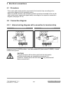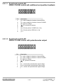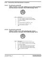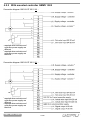
1
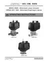
693, 698, 9698
GEMÜ 9698 - Motorized Linear Actuator
GEMÜ 693 / 698 - Motorized Diaphragm Valves
GB
OPERATING INSTRUCTIONS
GEMÜ 693
GEMÜ 698
GEMÜ 9698
693, 698, 9698
Contents
1
1.1
1.2
1.3
1.4
1.5
Notes for your safety
. . . . . . . . . . . . . . . . . . . . . . . . . . . . . . . .3
General notes
. . . . . . . . . . . . . . . . . . . . . . . . . . . . . . . .3
Explanation of symbols and signs
. . . . . . . . . . . . . . . . . . . . . . . . . . . . . . . .3
Safety notes
. . . . . . . . . . . . . . . . . . . . . . . . . . . . . . . .3
Correct use
. . . . . . . . . . . . . . . . . . . . . . . . . . . . . . . .4
Tools required for installation and connection . . . . . . . . . . . . . . . . . . . . . . . . . . . . .4
2
2.1
2.2
2.3
2.4
Manufacturer's information
Delivery
Functions
Versions
Operation and adjustment
. . . . . . . . . . . . . . . . . . . . . . . . . . . . . . . .4
. . . . . . . . . . . . . . . . . . . . . . . . . . . . . . . .4
. . . . . . . . . . . . . . . . . . . . . . . . . . . . . . . .4
. . . . . . . . . . . . . . . . . . . . . . . . . . . . . . . .5
. . . . . . . . . . . . . . . . . . . . . . . . . . . . . . . .5
3
3.1
3.2
3.3
3.4
Mechanical installation and mounting
Installation of the GEMÜ 693 / 698
Installation / mounting of the GEMÜ 9698
Mounting of a diaphragm valve
Manual override
. . . . . . . . . . . . . . . . . . . . . . . . . . . . . . . .7
. . . . . . . . . . . . . . . . . . . . . . . . . . . . . . . .7
. . . . . . . . . . . . . . . . . . . . . . . . . . . . . . . .7
. . . . . . . . . . . . . . . . . . . . . . . . . . . . . . . .7
. . . . . . . . . . . . . . . . . . . . . . . . . . . . . . . .8
4
4.1
4.2
4.2.1
4.2.1.1
Electrical connections
. . . . . . . . . . . . . . . . . . . . . . . . . . . . . . . .9
Procedure
. . . . . . . . . . . . . . . . . . . . . . . . . . . . . . . .9
Connection diagram
. . . . . . . . . . . . . . . . . . . . . . . . . . . . . . . .9
Internal wiring diagram with connection on terminal strip . . . . . . . . . . . . . . . . . . . . .9
Functional module AE - OPEN / CLOSE control
with additonal end position feedback
. . . . . . . . . . . . . . . . . . . . . . . . . . . . . . .10
4.2.1.2 Functional module AP - OPEN / CLOSE control
with potentiometer output
. . . . . . . . . . . . . . . . . . . . . . . . . . . . . . .10
4.2.2 Connection with Hirschmann connector
. . . . . . . . . . . . . . . . . . . . . . . . . . . . . . .11
4.2.2.1 Functional module AE - OPEN / CLOSE control
with additonal end position feedback and
Hirschmann connector N 6 R AM2 (Design: 6027) . . . . . . . . . . . . . . . . . . . . . . . . .11
4.2.2.2 Functional module AP - OPEN / CLOSE control
with potentiometer output and
Hirschmann connector N 6 R AM2 (Design: 6027) . . . . . . . . . . . . . . . . . . . . . . . . .11
4.2.3 With mounted controller GEMÜ 1283
. . . . . . . . . . . . . . . . . . . . . . . . . . . . . . .12
5
Technical data
. . . . . . . . . . . . . . . . . . . . . . . . . . . . . . .13
6
6.1
6.2
6.3
Order data
Order data for GEMÜ 9698
Order data for GEMÜ 693
Order data for GEMÜ 698
. . . . . . . . . . . . . . . . . . . . . . . . . . . . . . .13
. . . . . . . . . . . . . . . . . . . . . . . . . . . . . . .13
. . . . . . . . . . . . . . . . . . . . . . . . . . . . . . .14
. . . . . . . . . . . . . . . . . . . . . . . . . . . . . . .15
7
Manufacturer’s declaration / Note
. . . . . . . . . . . . . . . . . . . . . . . . . . . . . . .17
8
8.1
8.2
8.3
Dimensions
Dimensions - GEMÜ 9698
Dimensions - GEMÜ 693
Dimensions - GEMÜ 698
. . . . . . . . . . . . . . . . . . . . . . . . . . . . . . .17
. . . . . . . . . . . . . . . . . . . . . . . . . . . . . . .17
. . . . . . . . . . . . . . . . . . . . . . . . . . . . . . .18
. . . . . . . . . . . . . . . . . . . . . . . . . . . . . . .18
Goods return declaration
. . . . . . . . . . . . . . . . . . . . . . . . . . . . . . .19
EC Declaration of conformity
. . . . . . . . . . . . . . . . . . . . . . . . . . . . . . .20
9
693, 698, 9698
2/20
1 Notes for your safety
Please read the following notes carefully and observe them!
1.1 General notes
In order for the motorized linear actuator to function properly, the following conditions must
be fulfilled:
· proper transport and storage
· installation and commissioning by trained personnel
· operation in accordance to these operating instructions
· proper maintenance
Therefore, you must observe
· the information contained in these operating instructions
· the relevant safety regulations for the installation and operation of electric systems
· that this device must not be used in areas exposed to the danger of explosion.
The regulations, standards and directives mentioned in these operating instructions apply
only for Germany. If the GEMÜ 9698 (693/698) is used in other countries, the applicable
local regulations must be observed.
1.2 Explanation of symbols and signs
Important information in these operating instructions is emphasized by the following
symbols:
Endangerment of human life or health and/or considerable material
damage can occur if these instructions are not observed.
This symbol indicates Notices that provide important information on
your GEMÜ 9698 (693/698).
1.3 Safety notes
WARNING:
Electric shock can cause serious burns and fatal injuries!
· Only qualified and trained electricians are permitted to install, connect
and start up the GEMÜ 9698 (693/698)
· Make sure that the host devices are electrically safe
· Ensure compliance with the electrical data requirements
3/20
693, 698, 9698
1.4 Correct use
The GEMÜ 9698 is a motorized linear actuator for mounting on diaphragm valves.
A diaphragm valve with a built-on plastic valve body is supplied as GEMÜ type 693, or with
a metal valve body as GEMÜ type 698. The actuator performs a linear movement, which is
transferred to the diaphragm of the valve body by means of a spindle.
The actuator is built to protection class IP65.
1.5 Tools required for installation and connection
· Screwdriver (5 mm flat head) for loosening the cover and any potentiometer component
· Screwdriver (PH1 Philips head) for fixing the limit switch
· Screwdriver (3 mm flat head) for connecting power supply and signal cable to the
standard model terminal strip and for adjustment screws
· Various open-end wrenches and hexagon sockets for mounting the body
· Hexagon allen key (1.5 mm) for trigger cams
2 Manufacturer's information
2.1 Delivery
Inspect the product immediately upon delivery for missing parts or damage.
The delivery documents indicate the scope of delivery.
Compare the order numbers to determine that the correct model has been delivered and
that the order is complete.
The motorized linear actuator is already checked at the factory for function.
2.2 Functions
The motorized linear actuator is driven by means of a synchronous motor.
The power supply voltage must be 24V AC, 120V AC or 230V AC, 50 / 60 Hz, depending
on the model (voltage tolerance: +10%).
The change in frequency from 50 to 60 Hz results in reduction of the stroke time
from 20 sec. to 16 sec.
The motor transmits force via a toothed belt creating a rotary movement.
The rotary movement is converted into a lifting movement by means of a ball screw.
The valve CLOSED position set at the factory is suitable for up to 10 bar for sizes
DN 15 - 25 and up to 6 bar (4 bar for Teflon diaphragm DN 50) for sizes DN 32 - 50.
The valve end travel positions "OPEN" and "CLOSED" are achieved by limit switches.
The micro-switches (change-over contact) are wired internally as follows:
The break contact of the change-over contact to which the A.C. voltage is connected
opens when the trigger cam is actuated and the power supply is interrupted.
The make contact is closed, which allows a limit switch signal to be picked up
(e.g.: activation of a signal lamp).
693, 698, 9698
4/20
The potentiometer installed at the factory enables continuous detection of the position of
the actuator.
Optionally a three-point controller (GEMÜ 1283) can be added, which makes it possible to
control the actuator via a signal from 0 / 4 - 20 mA as a set value or via keys.
(As a special version, the GEMÜ 1283 position controller can also be used as a process
controller.
In this case, both the set value and the actual value can be defined externally.)
At a set value of 0 / 4 mA the actuator runs to the CLOSED position and at 20 mA to the
OPEN position (see GEMÜ 1283 operating instructions).
2.3 Versions
The actuator is available in the following versions:
GEMÜ 9698:
GEMÜ 693:
GEMÜ 698:
actuator without mounted valve body (e.g. as replacement actuator)
actuator with mounted plastic diaphragm valve body (diaphragm valve)
actuator with mounted metal diaphragm valve body (diaphragm valve)
All models are available in the standard version (OPEN - CLOSED), optionally with or
without potentiometer or with a mounted GEMÜ 1283 controller.
Detailed information on the various versions can be found in the order specifications
(see pages 14-17).
2.4 Operation and adjustment
The GEMÜ 9698 actuator is set in the open position when delivered.
The potentiometer component (if ordered) is disconnected from the transmission and must
be attached with the included screw after adjustment (see page 7).
The GEMÜ 693 / 698 motorized valves are set in the "OPEN" position when delivered. No
additional parts are required before installing the unit directly into the system. The motorized
valves can be installed directly in the system.
When mounting a GEMÜ 1283 controller, parameters can be changed or adjusted
according to the specific system; for information on this, please read the GEMÜ
1283 operating instructions!
WARNING:
Adjustments on the GEMÜ 9698 are conducted with the cover removed
and the unit connected to the power supply. Electric shock can cause
serious burns and fatal injuries. Therefore, adjustments must be
performed only by qualified electricians.
5/20
693, 698, 9698
Adjusting the actuator
1. Setting the CLOSED limit switch:
(Prerequisite: valve body and diaphragm are already mounted; (see chapter 3))
· Loosen cover screws (with 5mm flat-head screwdriver) and remove cover
· Using PH 1 Philips head screwdriver, loosen limit switch fixing screws 5, but do not remove
· Turn adjustment screw 4 (3mm flat head screwdriver) to position roller lever of the
CLOSED limit switch approx. 1 mm above the lower spindle guide
· Connect power supply to terminal 2 (L) and terminal 3 (N) → actuator runs to the CLOSED position
· Hold indicator spindle on the red marking → actuator closes completely, until motor stalls
· Release indicator spindle
· Disconnect power supply
· Loosen trigger cam screw using hexagon allen key (size 1.5)
· Press indicator spindle downward and fasten the trigger cam screw so that the cam
actuates the roller lever of the CLOSED limit switch = switch point
· Continue to turn adjustment screw 4 1 1/2 revolutions clockwise (jam safety).
(By continuing to turn the screw clockwise it is possible to reduce the pre-tension of the
diaphragm somewhat, which will increase the life of the diaphragm; however, if it is turned
too far, the valve will no longer seal properly)
· Check for leaks
· Fix CLOSED limit switch by means of limit switch fixing screws 5
2. Setting the OPEN limit switch:
(Prerequisite: Valve body and diaphragm already mounted (see chapter 3), CLOSED limit
switch set (see above))
· Using PH 1 Philips head screwdriver, loosen limit switch fixing screws 6, but do not remove)
· Drive actuator to OPEN direction past CLOSED limit switch and reverse towards
CLOSED until the CLOSED limit switch shuts off
· Turn the adjustment screw 3 clockwise to position the OPEN limit switch upward until it
stops (3mm flat blade screwdriver)
· Move actuator towards OPEN direction until the stroke length in the table below is
reached and switch off immediately → stroke length must correspond exactly.
· Turn the adjustment screw 3 anticlockwise to position the OPEN limit switch downward
until the switch point is made (audible click)
· Fix OPEN limit switch with limit switch fixing screws
DN:
15/25
stroke length in mm: 7.9
32/40
13.2
50
17.7
3
4
OPEN
limit
switch
CLOSED
limit
switch
6
5
roller lever
693, 698, 9698
lower spindle guide
6/20
3. Setting the potentiometer (functional module AP):
(Prerequisite: Valve body and diaphragm are already mounted (see chapter 3),
CLOSED limit switch and OPEN limit switch are set (see above))
a) Installation of potentiometer:
· To install the potentiometer support plate, loosen the 4 motor mount screws
· Push support plate in between (Caution: do not lift motor too much → otherwise toothed belt
will slip)
· Replace long screws with short screws (on potentiometer)
b) Setting the potentiometer:
· When the 9698 is delivered, the potentiometer is swiveled away from the actuator
· Connect power supply to terminal 2 (L) and terminal 3 (N)
→ actuator runs to the CLOSED position until limit switch shuts off
· Turn toothed gear of potentiometer (DN 50: lowest gear) clockwise until it reaches the stop
· Turn gear back 3 teeth
· Press potentiometer support plate onto the actuator gear and fix with enclosed screw
· To adjust the tooth clearance, loosen the other screw of the potentiometer support plate
(on the opposite side of the potentiometer)
· There must be some play in the toothed gear of the potentiometer:
Move plate anticlockwise: increases play in toothed gear
(Move plate clockwise: reduces play of toothed gear)
· Fix the potentiometer support plate screws
Toothed gear
increases play in gear
potentiometer support plate
reduces play in gear
Fixing screw
Loosen screw to adjust
play in gear
3 Mechanical installation and mounting
3.1 Installation of the GEMÜ 693 / 698
The GEMÜ 693 / 698 valves require no mechanical modification or additional extensions.
The valves can be installed directly into pipes by the chosen connection:
butt weld spigots, clamp connections or threaded connections (see pages 15-16).
3.2 Installation / mounting of the GEMÜ 9698
The GEMÜ 9698 motorized linear actuator must be connected to a diaphragm valve (then
corresponding to a GEMÜ 693 or 698).
Please note the following:
The GEMÜ 9698 actuator is in the open position when delivered.
The limit switches are not set, since this is only possible after the valve has been mounted.
The limit switch fixing screws are loose.
3.3 Mounting of a diaphragm valve
Mounting the valve body and diaphragm:
· Loosen cover screws (with 5mm flat-head screwdriver) and remove cover
· Connect power supply to terminal 2 (L) and 3 (N) → actuator runs to the CLOSED position
7/20
693, 698, 9698
· Switch off power supply
· for DN 15 / 25: Place washer and compressor on actuator shaft
for DN 32 / 40: Spring washers in the following arrangement: Place actuator----( ( ( ( ) ) ) )
and compressor on actuator shaft
for DN 50:
Spring washers in the following arrangement:
Place actuator----( ( ) ) ( ( ) ) ( ( and compressor on actuator shaft
· Turn diaphragm until stop - do not turn too far!
· Turn diaphragm back at least 180° but no more than 270° back to angled position,
so that the diaphragm tab lines up with small groove in the distance piece
· Connect power supply to terminal 1 (L) and (N) → actuator runs to the OPEN position
· Disconnect power supply as soon as the diaphragm lies loosely approx. 2 - 3 mm in
the depression of the lower part of the distance piece (exception: DN 50)
(With DN 50, the ball bearing spindle must not touch the lower spindle guide (see photo
on p. 6), since this will otherwise be destroyed, i.e. the diaphragm is outside of the
depression in the max. OPEN position and is only pressed in by the screws)
· Mount body and tighten 4 fastening screws in cross pattern until a small compression
bulge is visible on all 4 diaphragm sides
· Check for external leakage and tighten screws, if necessary. Retighten after use if
needed.
3.4 Manual override
Perform the following steps if you need the manual override:
· Unscrew position indicator transparent cover 1
· and pull out together with adapter 2
This unit forms the hand crank 3
· Remove the plug 4 on the actuator outer surface
· Press adapter 2 tightly into the opening 5
· Crank into desired valve position (in the direction on label)
If the actuator is equipped with a potentiometer, use of the emergency
hand crank may cause the potentiometer to move out of adjustment.
After a manual override, therefore, the potentiometer should be set
again according to chapter 2.4, before the actuator is operated again.
2
1
5
4
4
3
693, 698, 9698
8/20
4 Electrical connections
4.1 Procedure
· The on-site cable ends must be connected to the terminal strip according to the
connection diagram for the standard version
· With a mounted controller, the included connector must be connected to the on-site
cable ends (power supply and signal cable) according to the respective connection
diagram (see pages 10-13)
4.2 Connection diagram
4.2.1 Internal wiring diagram with connection to terminal strip
Functional module AE
open
Synchronous
motor
Functional module AP
open
closed
Synchronous
motor
closed
Actual value
potentiometer
Option
10 KΩ
PE
N
open
closed
N
PE
open
closed
linear
Diagram shows CLOSED position - cam has actuated S2 (limit switch CLOSED) → break
contact was opened.
CAUTION:
The potentiometer will be destroyed if both the limit switch
and the potentiometer are connected to terminals 5-8.
Therefore, connect either the limit switch or the potentiometer!
Never connect both!
9/20
693, 698, 9698
4.2.1.1 Functional module AE
OPEN / CLOSE control with additional end position feedback
1
Pin
2
3
4
5
6
7
8
Description
1
2
3
4
5
6
7
8
L1, motor voltage for direction of travel OPEN
L1, motor voltage for direction of travel CLOSED
N, reference voltage
, PE, protective conductor
n. c.
Us, S2 end position CLOSED [Us = Ub]
Us, S2 end position OPEN [Us = Ub]
n. c.
4.2.1.2 Functional module AP
OPEN / CLOSE control with potentiometer output
1
Pin
1
2
3
4
5
6
7
8
693, 698, 9698
2
3
4
5
6
7
8
Description
L1, motor voltage for direction of travel OPEN
L1, motor voltage for direction of travel CLOSED
N, reference voltage
, PE, protective conductor
n. c.
Us -, actual value potentiometer signal voltage
Us , actual value potentiometer signal output
Us +, actual value potentiometer signal voltage
10/20
4.2.2 Connection with Hirschmann connector
4.2.2.1 Functional module AE
OPEN / CLOSE control with additional end position feedback
and Hirschmann connector N 6 R AM2 (Design: 6027)
1
2
6
5
Pin
1
2
3
4
5
6
7
4
3
Description
L1, motor voltage for direction of travel OPEN
L1, motor voltage for direction of travel CLOSED
N, reference voltage
n. c.
Us, S2 end position CLOSED [Us = Ub]
Us, S2 end position OPEN [Us = Ub]
, PE, protective conductor
4.2.2.2 Functional module AP
OPEN / CLOSE control with potentiometer output
and Hirschmann connector N 6 R AM2 (Design: 6027)
1
2
6
5
Pin
1
2
3
4
5
6
7
3
4
Description
L1, motor voltage for direction of travel OPEN
L1, motor voltage for direction of travel CLOSED
N, reference voltage
Us +, actual value potentiometer signal voltage
Us -, actual value potentiometer signal output
Us , actual value potentiometer signal voltage
, PE, protective conductor
11/20
693, 698, 9698
4.2.3 With mounted controller GEMÜ 1283
Connection diagram 1283 000 Z XX 01 00 ...
required when actuator and
controller power supply are
different
2
required when actuator and
controller power supply are
identical
1
Connection diagram 1283 000 Z XX 01 01 ...
required when actuator and
controller power supply are
different
2
required when actuator and
controller power supply are
identical
1
693, 698, 9698
12/20
5 Technical data
Working medium
Ambient conditions of GEMÜ 698
Corrosive, inert, gaseous and liquid media which have
no negative impact on the physical and chemical
properties of the body and diaphragm material.
Ambient temperature
-10 ... +55° C
Storage temperature
-15 ... +55° C
Working medium temperature of GEMÜ 693
Valve body PVC-U
Valve body ABS
Valve body PP
Valve body PVDF
Permissible temperatures of GEMÜ 693
Storage temperature
-15 to +55° C
5 to 60° C
-20 to 60° C
5 to 80° C
-20 to 80° C
The permissible operating pressure depends on the working
medium temperature
Power consumption
10 VA
Rating
Continuously rated
Working medium temperatur of GEMÜ 698
Operating temperature max.
(depending on the medium wetted materials)
150° C
Operating time
Standard design
Ambient temperature of GEMÜ 693
Valve body PVC-U / PP
5 to 55° C
Valve body ABS / PVDF
-10 to 55° C
approx. 20 sec.
Protection class
IP 65 acc. to DIN 40050
Cable gland
2 x PG 13.5
6 Order data
6.1 Order data for GEMÜ 9698
13/20
693, 698, 9698
6.2 Order data for GEMÜ 693
Pressure / temperature correlation for plastic
Temperature in °C
(plastic body)
-20
-10
±0
5
Valve body material
PVC-U
ABS
PP-H
PVDF
Code 1
Code 4
Code 70/71
Code 20
10
20
25
30
40
50
60
70
80
1.5
2.0
4.0
6.3
2.7
5.4
1.5
4.7
permissible operating pressure in bar
10.0
10.0
10.0
10.0
10.0
10.0
10.0
10.0
10.0
10.0
10.0
10.0
10.0
10.0
10.0
10.0
10.0
10.0
10.0
10.0
10.0
10.0
8.0
8.0
8.5
9.0
6.0
6.0
7.0
8.0
3.5
4.0
5.5
7.1
Data for extended temperature ranges on request. Please note that the ambient temperature and medium temperature generate a combined
temperature at the valve body which must not exceed the above values.
Operating
pressure
MG DN EPDM / FPM
25
40
50
15
20
25
32
40
50
0 - 10 bar
0 - 6 bar
0 - 6 bar
PTFE
Kv
Weight
value (actuator only)
[m³/h]
0 - 6 bar
0 - 6 bar
0 - 4 bar
5.6
8.2
10.5
18.0
25.0
46.0
[kg]
Diaphragm material
O-ring material
CSM
EPDM
NBR
EPDM
FPM
FPM
EPDM
EPDM
PTFE
FPM
2.35
2.90
3.30
All pressures are gauge pressures. Operating pressure values were
determined with static operating pressure applied on one side of a
closed valve. Sealing at the valve seat and atmospheric sealing is
ensured for the given values.
Information on operating pressures applied on both sides and for
high purity media on request.
Kv values determined at p1 = 6 bar, EPDM diaphragm material,
Kv values: Tolerance ±10%.
MG = diaphragm size
Body configuration
O-ring material for
valve bodies with union ends
Code
2/2 way
Other combinations on request
Valve body material
Code
PVC-U, grey
1
ABS
4
PVDF
20
Inliner PPH - natural
70
Inliner PPH - grey acc. to RAL 7032
71
D
Diaphragm material
Connection
Code
Code
NBR
2
0
FPM
4
Spigots DIN for socket welding
Flanges EN 1092 / PN10 / form B
(ex DIN 2501 / PN10 / form C)
length EN 558-1, series 1
ISO 5752, basic series 1
Union ends with DIN insert (socket)
4
7
EPDM
14
PTFE/EPDM, PTFE laminated
52
Voltage / Frequency
Code
Spigots for IR butt welding
20
24 V 50/60 Hz
C4
Spigots for IR butt welding, BCF
28
120 V 50/60 Hz
G4
Spigots - inch
30
230 V 50/60 Hz
L4
Union ends with inch insert (socket)
Flanges ANSI class 125/150 RF,
length EN 558-2, series 1
ISO 5752, basic series 1
Union ends with DIN insert
(IR butt welding)
33
39
78
Functional module
Code
OPEN / CLOSE control
with additional end position feedback
OPEN / CLOSE control
with potentiometer output
AE
AP
For overview of available valve bodies see datasheet page 8
Order example
693
Type
693
Nominal size
15
0
1
14
L4
AE
15
Body configuration (code)
D
Connection (code)
0
Valve body material (code)
1
Diaphragm material (code)
14
Voltage / Frequency (code)
L4
Functional module (code)
693, 698, 9698
D
AE
14/20
6.3 Order data for GEMÜ 698
Operating pressure
Diaphragm size
DN
EPDM/FPM
[bar]
Weight
PTFE
15
25
2.7
0 - 10
20
0-6
2.8
25
3.1
32
40
40
50
[kg]
Butt weld spigots
50
0-6
0-6
0-6
0-4
7.0
7.5
11.5
All pressures are gauge pressures. Operating pressure values were determined with static operating pressure applied on one side of a closed
valve. Sealing at the valve seat and atmospheric sealing is ensured for the given values.
Information on operating pressures applied on both sides and for high purity media on request.
Kv values [m³/h]
DIN
MG
25
40
50
Code 0
DIN 11850
series 1
Code 16
Code 37
Code 59
EN ISO
1127
Code 60
15
4.1
4.7
4.7
4.7
-
-
7.4
20
6.3
7.0
7.0
7.0
-
4.4
13.2
25
13.9
15.0
15.0
15.0
12.6
12.2
16.2
32
25.3
27.0
27.0
27.0
26.2
-
30.0
40
29.3
30.9
30.9
30.9
30.2
29.5
32.8
50
46.5
48.4
48.4
48.4
51.7
50.6
55.2
DN
DIN 11850
series 2
Code 17
DIN 11850
series 3
Code 18
SMS 3008
ASME BPE
Kv values determined acc. to IEC 534 standard, inlet pressure 6 bar, ∆ p 1 bar, stainless steel valve body and soft elastomer diaphragm.
MG = Diaphragm size
Body configuration
Code
Tank bottom valve body
B**
2/2-way body
D
Multi-port design
M**
T-body
T*
* For dimensions see T Valves brochure
** Dimensions and versions on request or according to customer
requirements
Connections
Butt weld spigots
Spigots DIN
Spigots DIN 11850, series 1
Spigots DIN 11850, series 2
Spigots DIN 11850, series 3
Spigots DIN 11866, series A
Spigots JIS-G 3447
Spigots JIS-G 3459
Spigots SMS 3008
Spigots BS 4825, Part 1
Spigots ASME BPE
Spigots EN ISO 1127
Threaded connections
Threaded sockets DIN ISO 228
Threaded spigots DIN 11851
One side threaded spigot, other side
cone spigot and union nut, DIN 11851
Aseptic unions on request
Code
0
16
17
18
1A
35
36
37
55
59
60
Connections
Code
Flanges
Flanges EN 1092 / PN16 / form B,
length EN 558-1, series 1,
ISO 5752, basic series 1
Flanges ANSI class 125/150 RF,
length MSS SP-88
Flanges ANSI class 125/150 RF,
length EN 558-2, series 1,
ISO 5752, basic series 1
Clamp connections
Clamps ASME BPE for pipe ASME BPE,
short design
Clamps following ASME BPE for pipe
EN ISO 1127, length EN 558-1, series 7
Clamps ASME BPE for pipe ASME BPE,
length EN 558-1, series 7
Clamps DIN 32676 for pipe DIN 11850,
length EN 558-1, series 7
Clamps SMS 3017 for pipe SMS 3008,
length EN 558-1, series 7
8
38
39
80
82
88
8A
8E
For overview of available valve bodies see data sheet page 8
1
6
62
15/20
693, 698, 9698
Valve body material
Code
EN-GJL-250, (GG25)
EN-GJS-400-18-LT (GGG 40.3), PFA lined
EN-GJS-400-18-LT (GGG 40.3), PP lined
1.4435 - BN2 (CF3M), investment casting Fe<0.5%
1.4435 (ASTM A 351 CF3M, ≙ 316L),
investment casting
1.4408, investment casting
1.4408, investment casting, PFA lined
1.4435 (316L), forged body
1.4435 (BN2), forged body Fe<0.5%
EN-GJS-400-18-LT (GGG 40.3),
hard rubber lined
8
17
18
32
34*
37
39
40
42
Diaphragm material
Code
FPM
EPDM
EPDM
EPDM
EPDM
EPDM
PTFE/EPDM convex PTFE loose
PTFE/FPM convex PTFE loose
4
12**
13**
14
16**
17**
5E**
5F
max. 130°C*
max. 150°C*
max. 90°C*
max. 150°C*
max. 150°C*
max. 150°C*
max. 150°C*
* Steam sterilization temperature / 20 min
** Material complies with FDA requirements
83
Supply voltage
* Material equivalency 316 L
24 V
120 V
230 V
Code
± 10%
± 10%
± 10%
C
G
L
Mains frequency
Code
50/60 Hz
4
Functional module
Code
OPEN / CLOSE control
with additional end position feedback
OPEN / CLOSE control
with potentiometer output
AE
AP
Valve body surface finish, internal contour
Code
Ra ≤ 6.3 μm
blasted internal/external
1500*
Ra ≤ 6.3 μm
electropolished internal/external
1509*
Ra ≤ 0.8 μm
mechanically polished internal, blasted external
1502
Ra ≤ 0.8 μm
electropolished internal/external
1503
Ra ≤ 0.6 μm
mechanically polished internal, blasted external
1507
Ra ≤ 0.6 μm
electropolished internal/external
1508
Ra ≤ 0.4 μm
mechanically polished internal, blasted external
1536
Ra ≤ 0.4 μm
electropolished internal/external
1537
Ra ≤ 0.25 μm
mechanically polished internal, blasted external
1527
Ra ≤ 0.25 μm
electropolished internal/external
1516
Ra acc. to DIN 4768; at defined reference points
Order example
698
Type
Nominal size
Body configuration (code)
Connection (code)
Valve body material (code)
Diaphragm material (code)
Supply voltage (code)
Mains frequency (code)
Functional module (code)
Surface finish (code)
698
693, 698, 9698
* only investment cast design
25
D
60
34
12
L
4
AE
1500
25
D
60
34
12
L
4
AE
1500
16/20
7 Manufacturer’s declaration / Note
Manufacturer's Declaration
According to the EC Machinery Directive 2006/42/EC, Annex II B
We hereby declare that the device described in this specification is intended for installation in a
machine or application whose commissioning ist prohibited until it has been determined that this
machine / application conforms to EC Machinery Directive 2006/42/EC.
Handling, assembly and commissioning, in addition to setting and adjustment of the machine must
be performed only by authorised specialist staff.
Note: Connection and adjustment of the machine must be performed only by authorised service
personnel. The manufacturer shall assume no liability for damages resulting from improper use or
unauthorized actions. In case of doubt, please contact us before initial operation.
8 Dimensions
8.1 Dimensions - GEMÜ 9698
All dimensions in mm
17/20
693, 698, 9698
8.2 Dimensions - GEMÜ 693
8.3 Dimensions - GEMÜ 698
Actuator dimensions
of GEMÜ 693 [mm]
Actuator dimensions
of GEMÜ 698 [mm]
MG
DN
A
A1
MG
DN
A
A1
25
40
50
15 - 25
32 - 40
50
222
271
278
82
131
138
25
40
50
15 - 25
32 - 40
50
222
271
278
82
131
138
MG = Diaphragm size
The dimensions of the valve bodies see
data sheet of GEMÜ 693.
693, 698, 9698
MG = Diaphragm size
The dimensions of the valve bodies see
data sheet of GEMÜ 698.
18/20
Goods return declaration (copy specimen)
Legal regulations for the protection of the environment and personnel require that you include the
completed and signed goods return declaration with the dispatch documents.
If this declaration is not completed or not included with the dispatch documents, your return
will not be processed!
If the valve / device was operated with poisonous, corrosive, flammable, aggressive or waterendangering media, all medium wetted parts must be emptied carefully, decontaminated and rinsed.
Select an appropriate transport container, label it with the name of medium which the valve / device
had made contact. This serves to avoid personal injury or damage to property from remains of media.
Company details:
Valve / device information
Company . . . . . . . . . . . . . . . . . . . . . . . . . . . . . . . . .
Type: . . . . . . . . . . . . . . . . . . . . . . . . . . . . . . . . . . . .
Address . . . . . . . . . . . . . . . . . . . . . . . . . . . . . . . . . .
Year of manufacture: . . . . . . . . . . . . . . . . . . . . . . . .
.........................................
Serial number: . . . . . . . . . . . . . . . . . . . . . . . . . . . . .
Contact person . . . . . . . . . . . . . . . . . . . . . . . . . . . .
Ambient temperature: . . . . . . . . . . . . . . . . . . . . . . .
Telephone number . . . . . . . . . . . . . . . . . . . . . . . . .
Media: . . . . . . . . . . . . . . . . . . . . . . . . . . . . . . . . . . .
Fax number . . . . . . . . . . . . . . . . . . . . . . . . . . . . . . .
.........................................
E-Mail . . . . . . . . . . . . . . . . . . . . . . . . . . . . . . . . . . . .
.........................................
Reason for return:
Concentration: . . . . . . . . . . . . . . . . . . . . . . . . . . . . .
.........................................
.........................................
.........................................
.........................................
.........................................
Operating temperature: . . . . . . . . . . . . . . . . . . . . . .
.........................................
Operating pressure: . . . . . . . . . . . . . . . . . . . . . . . .
.........................................
Viscosity: . . . . . . . . . . . . . . . . . . . . . . . . . . . . . . . . .
.........................................
Solids content: . . . . . . . . . . . . . . . . . . . . . . . . . . . . .
Please tick the relevant warning labels:
radioactive
explosive
corrosive
poisonous
harmful
to health
biohazardous
oxidising
harmless
We herewith declare that the returned parts were cleaned and that according to danger protection
regulations there is no danger from remains of media for persons or for the environment.
Location, Date . . . . . . . . . . . . . . . . . . . . . . . . . . . . .
Stamp / signature . . . . . . . . . . . . . . . . . . . . . . . . . .
19/20
693, 698, 9698
9 EG-Konformitätserklärung
Declaration of Conformity
According to annex VII of the Directive
97/23/EC
Hereby we,
GEMÜ Gebr. Müller GmbH & Co. KG
Fritz-Müller-Straße 6-8
D-74653 Ingelfingen
declare that the equipment listed below complies with the safety requirements of
the Pressure Equipment Directive 97/23/EC.
Description of the equipment - product type
Diaphragm valve
GEMÜ 693, GEMÜ 698
Conformity assessment procedure:
Module H
Valves DN ≤ 25 comply with section 3§3 of the Pressure Equipment Directive
97/23/EC. They are not identified with a CE label as per Pressure Equipment
Directive 97/23/EC and no conformity is declared.
Management
VALVES, MEASUREMENT
AND CONTROL SYSTEMS
GEMÜ Gebr. Müller Apparatebau GmbH & Co. KG · Fritz-Müller-Str. 6-8 · D-74653 Ingelfingen-Criesbach
Phone +49 (0) 7940/123-0 · Telefax +49 (0) 7940/123-224 · [email protected] · www.gemue.de
*88237958*
Number:
Certificate no.:
TÜV Rheinland
Berlin Brandenburg
0035
01 202 926/Q-02 0036
Subject to alteration · 02/2009 · 88237958
Notified body: