Transcript
TECHNICAL SPECIFICATIONS
EN
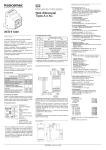
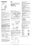
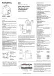
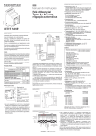
RESYS 058 B
Operating instructions
Earth leakage relay
A and AC types
RESYS M40
> Configuration (DIP switch)
Switch
This differential relay conforms to type A which trips
sinusoidal alternating currents and pulsed currents,
whether they are applied suddenly or change slowly.
This product is also immune to interference.
This relay must be installed in accordance with the
regulations currently in force.
The device must be checked periodically to see that it
complies with the regulations.
B
AL1
AL2
0
0
Positive security
Positive security
1
0
Negative security
Pre-alarm (neg. security)
0
1
Negative security*
Positive security*
1
1
Negative security
Pre-alarm (pos. security)
C
Storage mode
1
Automatic reset
0
Storage mode*
D
Toroidal transformer ratio
1
600 : 1 > Socomec* toroid
TERMINAL CONNECTION DIAGRAM
> Test Function
Bargraph blinks
“Trip” LED and “Alarm” relay activated
> Continuous monitoring
Test OK
NO
NO
Toroid input short circuit
NO
NO
Relay/Toroid connection break
YES
NO
Test OK
YES
YES
Toroid input short circuit
NO
NO
Relay/Toroid connection break
YES
NO
Outputs
0
1000 : 1 > other manufacturers
* factory configuration
• (negative security: relay excited in case of alarm/positive security: relay not excited in case of alarm).
reset
> Note
SwitchRelay configuration
A
50m maxi
Installation must only be carried out by qualified personnel.
Before installation, disconnect from the power supply.
Connect the device as shown on the diagram below
(N.B. some optional functions do not need to be cabled).
When installing the device, make the connections
between the relay and the differential toroid as short as
possible.
Do not put relay cables or the differential toroid beside
power conductors.
Do not place differential toroids close to sources of
intense magnetic fields.
test
INSTALLATION
A1 (+)
12-125 VDC
230 VAC*
400 VAC
A3 115 VAC* Only
0
A2 (-)
L1
L2
L3
N
PE
>A
ctivation of “Test” button
(Press (>1s) or external button)
8 9 10 11 12 13 14
Toroid
Alarm 1
(AL1)
50m** maxi
When the measured current exceeds 50% of the threshold value, the pre-alarm relay changes state (if selected in this mode). Automatic reset to its original state if
30% lower than pre-set threshold.
> Description of front panel
1 - Adjustment/setting I∆n
2-G
reen “ON” LED
3 - “RESET” button
4 - Red “TRIP” alarm LED
5 - LED bargraph (% x I∆n)
6-C
onfiguration DIP switch
(x 4)
7 - “TEST” push-button
8 - Time setting
Alarm 2 (AL2)
or Pre-alarm
> References :
* Dual voltage supply only available on 115/230 VAC model. For
Us = 115VAC, connect the supply to terminals 6 and 7. For the
other supply options, cable between 5 and 7.
The output relays are shown in the non-excited state (for
example, as if the auxiliary supply was not present)
The protective earth wire must not pass through the toroid. For
single-phase applications, only the phase and the neutral must
pass through the toroid.
** Cabling: For distances > 1 m, use a twisted pair for connection
between the relay and the toroid.
> Troubleshooting
If the product is not working properly, check that is it properly
connected.
DIMENSIONS
44 mm
63.5 mm
49.5 mm
SOCOMEC - Ref. : 541 612 B
61 mm
45 mm
30 mm
85 mm
• With I∆n set at 30 mA, the timing is set at 0 (instantaneous) and can not be modified.
• The pre-configured factory setting for the device is 30
mA/0s. These values can be modified as needed for
operation. A plastic seal is provided with the device
in order to lock the protective cover and ensure the
settings.
- Number of contacts: 1
changeover contact relay +
1 single contact relay
- Type of contact :
Alarm 1 (12,13,14)
AC1 (250 V) 8 A (2000 VA)
AC15 (250 V) 2,5 A
DC1 (25 V) 8 A (200 W)
Alarm 2 / Pre-alarm (10,11)
AC1 (250 V) 6 A (1500 VA)
AC15 (250 V) 4 A
DC1 (25 V) 6 A (150 W)
- Lifetime: 150 000 operations at nominal load
- Dielectric voltage: 2 kV AC (rms) IEC 60947-1
- Impulse voltage: 4 kV (1,2 kV/ 50 µs) IEC 60664
• Remote Test and Reset (1, 2, 3) :
With N.O. contact (e.g. push-button)
Min. contact closure time: ≥ 80 ms
• Box : grey, self-extinguishable, Lexan UL94 VO
• Weight: ≈ 190 g (AC) / ≈ 110 g (DC)
• Mounting: on 35 mm symmetrical DIN rail
(BS5584 : 1978 - EN50 002 - DIN 46277-3)
• Connecting terminal:
≤ 2,5 mm2 flexible, ≤ 4 mm2 rigid
• Certification:
conforms to IEC 60755, 60947, 61543, 61000-4-2,
61000-4-3, 61000-4-4, 61000-4-5, 61000-4-6,
61000-4-12, 61000-4-16.
CE compliant.
1 2 3 4 5 6 7
> Pre-alarm function
• Us supply (5, 6, 7):
12 - 125 VDC (85 – 110 % de Us)
115/230, 400 VAC (85 - 115 % de Us) (see terminal
connection diagram). All AC supplies are galvanically
isolated frm toroid, TEST and RESET inputs.
• Frequency: 50/60Hz (AC supply)
• Isolation : Over-voltage cat. III
• Impulse voltage:
2,5 kV (115 V AC supply)
(1,2 kV/ 50 µs) IEC 60664
4 kV (230 and 400 VAC supply)
• Consumption (max.) :
6VA (AC supply) - 5W (DC supply)
• Measured residual current:
0 to 30A (15-400 Hz) (via external toroid with ratio 600:1
or 1000: 1 connected to terminals 8 and 9)
• Sensitivity I∆n :
30, 100, 300, 500 mA, 1, 3, 5, 10, 30 A (adjustable)
• Tripping accuracy: 80 - 90% of I∆n
• Reset value: ≈ 85% of trip threshold
• Time delay I∆s : 0*, 60, 150, 300, 500, 800 ms, 1, 4, 10 s
(adjustable) *time set for “0” or “Instantaneous” < 25 ms
for residual current @ 5 x I∆n.
• Reset time: < 2s (after eliminating the auxiliary power
supply)
• Indication des Leds :
- Power supply present: green
- Bargraph : 3 green (30, 50 and 70% of the threshold
value set)
- Tripping: red
• Operating temperature: -20 to +55° C
• Storage temperature: -30 to +70° C
• Relative humidity: +95 %
Auxiliary power supply:
12-125 VDC
115/230 VAC
400 VAC
Reference
4941 3602
4941 3723
4941 3740
> Accessories
Toroids (C.T.) :
∆IC - Ø 15 mm ∆IC - Ø 30 mm ∆IC - Ø 50 mm ∆IC - Ø 80 mm ∆IC - Ø 120 mm ∆IC - Ø 200 mm ∆IC - Ø 300 mm 4950 6015
4950 6030
4950 6050
4950 6080
4950 6120
4950 6200
4950 6300
Use of toroids ≥ 120 mm: setting I∆n min = 300 mA
Other toroids: consult us