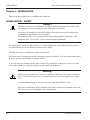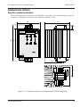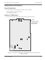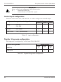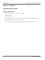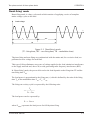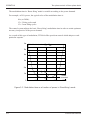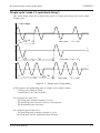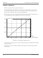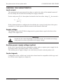
1
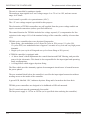
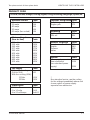
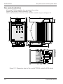
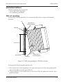
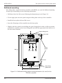
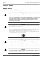
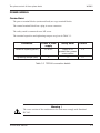
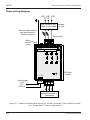
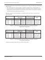
Two-phase control of three-phase loads
TE200A
Power controllers
Two-phase control
of three-phase loads
User manual
©Copyright Eurotherm Automation 1997
All rights reserved. All reproduction or transmission in any form or using any procedure
(electronic or mechanical, including photocopying or recording) without written authorisation
from EUROTHERM AUTOMATION is strictly prohibited.
EUROTHERM AUTOMATION has made every effort to ensure that the specification given in
this manual is as accurate and up to the minute as possible. However, in order to maintain our
‘leading edge’, it may be necessary to make certain changes or omissions to our specification. We
cannot be held responsible for any damage to persons or property or for any financial loss or costs
arising from this.
TE200A User manual HA175773ENG Iss 1 10/97
i
Two-phase control of three-phase loads
TE200A
USER MANUAL
CONTENTS
Page
EUROPEAN DIRECTIVES . . . . . . . . . . . . . . . . . . . . . . . . . .iv
CE MARKING AND SAFETY . . . . . . . . . . . . . . . . . . . . . . .iv
ELECTROMAGNETIC COMPATIBILITY (EMC) . . . . . . .iv
DECLARATION OF CE CONFORMITY . . . . . . . . . . . . . . .v
PRECAUTIONS . . . . . . . . . . . . . . . . . . . . . . . . . . . . . . . . . . .vi
CHAPTER 1
IDENTIFYING THE CONTROLLERS . . . . . . . . . . . . . . . .1-2
GENERAL INTRODUCTION TO THE TE200A SERIES .1-2
TECHNICAL SPECIFICATION . . . . . . . . . . . . . . . . . . . . .1-5
PRODUCT CODE . . . . . . . . . . . . . . . . . . . . . . . . . . . . . . . .1-7
EXAMPLE OF PRODUCT CODE . . . . . . . . . . . . . . . . . . .1-8
SERIAL NUMBER LABELS . . . . . . . . . . . . . . . . . . . . . . .1-8
CHAPTER 2
INSTALLATION . . . . . . . . . . . . . . . . . . . . . . . . . . . . . . . . .2-2
INSTALLATION - SAFETY . . . . . . . . . . . . . . . . . . . . . . . .2-2
DIMENSIONAL DETAILS . . . . . . . . . . . . . . . . . . . . . . . . .2-3
MOUNTING DETAILS . . . . . . . . . . . . . . . . . . . . . . . . . . . .2-5
CHAPTER 3
WIRING . . . . . . . . . . . . . . . . . . . . . . . . . . . . . . . . . . . . . . . .3-2
WIRING - SAFETY . . . . . . . . . . . . . . . . . . . . . . . . . . . . . . .3-2
POWER WIRING . . . . . . . . . . . . . . . . . . . . . . . . . . . . . . . . .3-3
USER TERMINAL BLOCKS . . . . . . . . . . . . . . . . . . . . . . .3-5
ii
TE200A User manual
Two-phase control of three-phase loads
Page
CHAPTER 4
CONFIGURATION . . . . . . . . . . . . . . . . . . . . . . . . . . . . . . .4-2
CONFIGURATION - SAFETY . . . . . . . . . . . . . . . . . . . . . .4-2
DRIVER BOARD CONFIGURATION . . . . . . . . . . . . . . . .4-3
CHAPTER 5
OPERATION . . . . . . . . . . . . . . . . . . . . . . . . . . . . . . . . . . . .5-2
THYRISTOR FIRING MODES . . . . . . . . . . . . . . . . . . . . . .5-2
CONTROL OPERATION . . . . . . . . . . . . . . . . . . . . . . . . . . .5-6
CHAPTER 6
COMMISSIONING PROCEDURE . . . . . . . . . . . . . . . . . . .6-2
COMMISSIONING PROCEDURE - SAFETY . . . . . . . . . .6-2
CHECKING THE CHARACTERISTICS . . . . . . . . . . . . . .6-3
POWERING UP THE CONTROLLER . . . . . . . . . . . . . . . .6-4
CHAPTER 7
MAINTENANCE . . . . . . . . . . . . . . . . . . . . . . . . . . . . . . . . .7-2
FUSES . . . . . . . . . . . . . . . . . . . . . . . . . . . . . . . . . . . . . . . . . .7-2
SERVICING . . . . . . . . . . . . . . . . . . . . . . . . . . . . . . . . . . . . .7-5
TOOLS . . . . . . . . . . . . . . . . . . . . . . . . . . . . . . . . . . . . . . . . .7-5
TE200A User manual
iii
Two-phase control of three-phase loads
EUROPEAN DIRECTIVES
CE MARKING AND SAFETY
TE200A products carry the CE mark in compliance with the essential requirements of the
European Low Voltage Directive 73/23/EEC of 19/2/73 (amended by the Directive
93/68/EEC of 22/7/93).
For safety reasons, TE200A products installed and used in compliance with this User Manual
meet the essential requirements of the European Low Voltage Directive.
ELECTROMAGNETIC COMPATIBILITY (EMC)
For an industrial environment only, must not be used in domestic environments.
Eurotherm certifies that TE200A products, installed and used in compliance with these
Instructions, meet the following EMC standards and enable the system which incorporates
them to comply with the EMC Directive, as far as the TE200A products are concerned.
EMC test standards
Immunity
Generic standard
Test standards
:
:
Emission
Generic standard
Test standard
Product standard
:
:
:
EN 50082-2
EN 61000-4-2, EN 61000-4-4, ENV 50140, ENV 50141
ENV 50204
EN 50081-2
EN 55011 Class A
IEC 1800-3 (second environment)
Internal EMC filters
EMC filters are incorporated in the TE200A to reduce conducted emission in accordance with
the corresponding test standard.
EMC Guide
In order to help you reduce the effects of electromagnetic interference depending on the product installation, Eurotherm can supply you with the 'Electromagnetic Compatibility'
Installation Guide (ref: HA 025464).
This guide lists the rules generally applicable for EMC.
iv
TE200A User manual
Two-phase control of three-phase loads
DECLARATION OF CE CONFORMITY
A declaration of CE conformity is available on request.
Validation by Competent Body
Eurotherm has validated the compliance of TE200A products with the European Low Voltage
Directive and with EMC standards through product design and laboratory testing.
The tests carried out on TE200A products are listed in a Technical Construction File validated
by the LCIE (Central Laboratory for the Electrical Industries), a Recognised Competent Body.
Further information
For any further information, or if in doubt, please contact Eurotherm Controls where qualified
staff are available to advise or assist you with the commissioning of your installation.
TE200A User manual
v
Two-phase control of three-phase loads
PRECAUTIONS
Safety symbols
Important safety precautions and special information are indicated in the text of the manual by
two symbols:
DANGER
!
WARNING
This symbol means that failure to take note of the information given in this manual
may have serious consequences for the safety of personnel and may even result in
electrocution.
This symbol means that failure to take note of the information may
• have serious consequences for the installation or
• lead to the incorrect operation of the power unit.
These symbols must be observed for particular points.
However the whole of the manual remains applicable.
Personnel
The installation, configuration, commissioning and maintenance of the power unit should
only be carried out by personnel qualified and trained to work with low voltage electrical
equipment in an industrial environment.
Independent alarm
Given the value of the equipment controlled by TE200A products it is the responsibility of the
user, and it is highly recommended, that an independent safety device (alarm) should be
installed. This alarm must be tested regularly.
Eurotherm can supply suitable equipment.
vi
TE200A User manual
Two-phase control of three-phase loads
IDENTIFYING THE CONTROLLERS
Chapter 1
IDENTIFYING THE TE200A POWER CONTROLLERS
Page
GENERAL INTRODUCTION TO THE TE200A SERIES . . . . . . .1-2
TECHNICAL SPECIFICATION . . . . . . . . . . . . . . . . . . . . . . . . . . .1-5
PRODUCT CODE . . . . . . . . . . . . . . . . . . . . . . . . . . . . . . . . . . . . . .1-7
EXAMPLE OF PRODUCT CODE . . . . . . . . . . . . . . . . . . . . . . . . .1-8
SERIAL NUMBER LABELS . . . . . . . . . . . . . . . . . . . . . . . . . . . . .1-8
TE200A User manual
1-1
IDENTIFYING THE CONTROLLERS
Two-phase control of three-phase loads
Chapter 1 IDENTIFYING THE CONTROLLERS
GENERAL INTRODUCTION TO THE TE200A SERIES
The TE200A series of controllers are thyristor units designed to control the electrical power in
industrial three-phase loads.
A TE200A series controller is made up of two channels, each comprising a pair of thyristors
connected in anti-parallel, and a direct (unswitched) channel.
The TE200A series is designed to control three-phase resistive loads:
• elements with a low temperature coefficient
• short-wave infrared elements (except for the 63A model).
Three-phase loads can be connected:
• in star without neutral
• in closed delta
The wiring of the controller is independent of the supply phase rotation.
The nominal line-to-line voltage ranges¡ from 200Vac to 500Vac.
The nominal currents, defined at an ambient temperature of 45°C, of TE200A series
controllers are between 16A and 63A, per phase.
70
IN= 63A (fan-cooled)
Ieff (A)
60
IN= 50A
50
40
30
IN= 25A
IN= 40A
20
10
IN= 16A
Operating temperature (°C)
0
20
25
30
35
40
45
50
55
60
Figure 1-1 Current derating per phase as a function of ambient temperature
(dotted line: current limited by recommended fuse)
1-2
TE200A User manual
Two-phase control of three-phase loads
IDENTIFYING THE CONTROLLERS
Heatsink
Supply terminal block
Auxiliary power
supply option
Upper protection cover
TE200A
EUROTHER
M
40A/400V
ε
R
(L1)
S
(L2)
T
(L3)
U
(T1)
V
(T2)
W
(T3)
- + 5V
9 8
7
LED firing indicator
Control signal connector
Load terminal block
Figure 1-2 Overview of the TE200A series controller (non fan-cooled unit)
TE200A User manual
1-3
IDENTIFYING THE CONTROLLERS
Two-phase control of three-phase loads
The unit is controlled by analogue signals.
The analogue input signals have two voltage ranges: 0 to 5V or 0 to 10V, and one current
range: 4 to 20mA.
Local control is possible via a potentiometer (10kΩ).
The +5V user-voltage output is provided for this purpose.
The electronics of TE200A controllers are self-supplied from the power voltage and do not
require external connections (unless specified otherwise).
The control function for TE200A includes line voltage squared (V2) compensation for line
variations in the range ±10% of the nominal voltage of the controller; stability is better than
±2%.
TE200A series controllers have two thyristor firing modes:
• Burst-firing - the modulation cycle is from 30 cycles at 50% power (15 cycles ON,
15 cycles OFF) to a modulation time of approx 6 seconds at very low and very high power
demands.
• Single-cycle (one cycle of firing and one cycle of non-firing at 50% power).
A TE200A controller is equipped with:
• A ‘driver board’ which implements the control function and EMC filtering, and provides
power for the electronics. This board is also responsible for the input signal and operating
mode configurations.
• A ‘firing board’ which triggers thyristor firing.
The filter which provides immunity against electromagnetic interference is located between
the power phases.
The user terminal block below the controller is used for the input signal connection without
needing access to the inside of the controller.
A green LED, labelled ‘ON’, indicates thyristor firing and is located on the front facia.
TE200A power controllers are designed to be bulkhead or DIN rail mounted.
The 63A rated unit must be permanently fan-cooled.
The fan power supply is 115Vac or 230Vac (to be specified when ordering the controller).
1-4
TE200A User manual
Two-phase control of three-phase loads
IDENTIFYING THE CONTROLLERS
TECHNICAL SPECIFICATION
The TE200A series of thyristor units is intended for two-phase control of an industrial
three-phase load.
Power
Nominal current (per phase)
Line-to-line voltage
Operating voltage (calibration)
Supply frequency
Dissipated power (thyristor unit)
Dissipated power (external fuses)
Insulation (1 min test)
Cooling
Fan power supply (63A unit)
Load
Supply phases
Load configuration
Fuses
16A, 25A, 40A, 50A or 63A (at 45°C)
200Vac to 500Vac (±10%)
200V to 277V and 380V to 500V
50Hz and 60Hz (±2Hz) automatic selection
1.3W (approx.) per amp, per phase
0.7W (approx.) per amp per phase
In series 2000Vac, 50Hz between power and earth and
3600Vac, 50Hz between power and control
Natural convection for 16A to 50A ratings Permanent fancooling for 63A rating
115Vac or 230Vac (selected in order code)
Resistive three-phase load with a low temperature
coefficient
Short-wave infrared elements (except for 63A rating)
Wiring independent of the phase rotation
3-wire: Closed delta or star without neutral
External (order separately) - see chapter 7
CE Marking
Electrical safety
TE200A controllers carry the CE mark in compliance with
the essential requirements of the European Low Voltage
Directive 73/23/EC (amended by the Directive 93/68/EC)
Electromagnetic compatibility
Immunity and Emissions
TE200A products comply with Electromagnetic
Compatibility test standards (see page iv).
Control
External control signal
Input impedance (approx.)
Configuration
Local control
TE200A User manual
Analogue
Voltage: 0 to 5V or 0 to 10V. Current 4 to 20mA
Voltage input: 100kΩ, current input: 250Ω
‘Coffee beans’ on driver board
10kW potentiometer supplied by +5V user-voltage
(input configured as 0 to 5V)
1-5
IDENTIFYING THE CONTROLLERS
Two-phase control of three-phase loads
Thyristor firing
Firing modes
Switching
Indication
Burst-firing: Number of firing and non-firing cycles at
50% power: 15 ±2
Single-cycle: One firing cycle and one non-firing cycle at
50% power
Conduction starts and ends at zero voltage
Thyristor firing is signalled by a green LED
Control performance
Control type
Linearity
Stability
The total power controlled in the three-phase load (supply
voltage squared) is proportional to the setpoint
Better than ±2% of full scale
With ±10% variations of the supply voltage, stability is
better than ±2% of full scale
Option
Auxiliary power supply
It is possible to operate on non-standard three-phase
supply by separately supplying the electronics with
115Vac or 230Vac
Environment
Operating temperature
Storage temperature
Thyristor protection
Protection
External wiring
Operating atmosphere
Humidity
Pollution
0°C to +60°C at maximum altitude of 2000m (see derating
curves)
-10°C to +70°C
High-speed external fuses - ordered separatley (see
chapter 7)
(except for short-wave infrared application)
Internal MOVs (varistors) and RC snubbers
IP20 (in compliance with Standard IEC 529)
To be carried out in compliance with Standard IEC 364
Non-explosive, non-corrosive, non-conductive
RH: 5% to 95%, non-condensing, non-streaming
Pollution degree 2 permissible, defined by IEC 664
Over-voltage category III, defined by IEC 664
In order to maintain its 'leading edge', Eurotherm may have to make changes to its specifications without advance notice.
For any further information, or if in doubt, please contact Eurotherm Controls.
1-6
TE200A User manual
Two-phase control of three-phase loads
IDENTIFYING THE CONTROLLERS
PRODUCT CODE
TE200A/Current/Voltage/Cooling/Signal/Firing/Mounting/Language/Option/00
Nominal current
16 amps
25 amps
40 amps
50 amps
63 amps (fan cooled)
Code
16A
25A
40A
50A
63A
Mains voltage*
(line-to-line)
200 volts
230 volts
240 volts
277 volts
380 volts
400 volts
415 volts
440 volts
480 volts
500 volts
Code
200V
230V
240V
277V
380V
400V
415V
440V
480V
500V
Fan supply
Without fan-cooling
(16A to 50A)
With fan-cooling (63A):
115Vac
230Vac
Input signal
0 to 5 volts
0 to 10 volts
4 to 20 milliamps
TE200A User manual
Thyristor firing mode Code
Burst-firing
FC
Single-cycle
FC1
Mounting
Bulkhead
DIN rail
Code
BKD
DIN
Manual language
French
English
German
Italian
Code
FRA
ENG
GER
ITA
Option*
Power supply separate
from electronics
(non-standard power
supply)
Code
115V
230V
Code
000
115V
230V
Code
0V5
0V10
4mA20
*
Non-standard mains: use the coding
for the voltage immediately above and
choose option of power supply
separate from electronics.
1-7
IDENTIFYING THE CONTROLLERS
Two-phase control of three-phase loads
EXAMPLE OF PRODUCT CODE
Controller and installation parameters
Nominal load current
Nominal supply voltage
Input signal
Firing mode
Mounting
User manual
35 amps
415 volts line-to-line
0 to 5 volts
Single-cycle
On DIN rails
In English
Controller code:
TE200A / 40A / 415V / 000 / 0V5 / FC1 / DIN / ENG / 00
SERIAL NUMBER LABELS
Two identification labels provide all the information relating to the factory settings of the
controller.
The identification labels are located on the sides of the unit.
EUROTHERM
WORTHING, ENGLAND : 1903 268500
MODEL : TE200A/40A/415V/000/0V5/FC1/DIN/ENG/00
2.20
SERIAL No. : INT100/002/001/10/97
0F222935
CURRENT : 40A VOLTAGE : 415V
AUX. POWER SUPPLY : SELF-SUPPLIED
INPUT
: 0-5V
FAN POWER SUPPLY : NONE
FIRING
: SINGLE-CYCLE
FUSE
: FERRAZ B093910. ANY NON-SPECIFIED FUSE INVALIDATES GUARANTEE
Figure 1-3 Example of identification labels for a TE200A controller
The information corresponds to the product code example
Warning!
Following any re-configuration on the part of the user, there is no guarantee that the controller
will correspond to the label information
1-8
TE200A User manual
Two-phase control of three-phase loads
INSTALLATION
Chapter 2
INSTALLATION
Page
INSTALLATION - SAFETY . . . . . . . . . . . . . . . . . . . . . . . . . . . . . .2-2
DIMENSIONAL DETAILS . . . . . . . . . . . . . . . . . . . . . . . . . . . . . . .2-3
Non fan-cooled controllers . . . . . . . . . . . . . . . . . . . . . . . . . . . . .2-3
Fan-cooled controllers . . . . . . . . . . . . . . . . . . . . . . . . . . . . . . . .2-4
MOUNTING DETAILS . . . . . . . . . . . . . . . . . . . . . . . . . . . . . . . . . .2-5
DIN rail mounting . . . . . . . . . . . . . . . . . . . . . . . . . . . . . . . . . . .2-5
Bulkhead mounting . . . . . . . . . . . . . . . . . . . . . . . . . . . . . . . . . . .2-6
TE200A User manual
2-1
INSTALLATION
Two-phase control of three-phase loads
Chapter 2 INSTALLATION
Please read thoroughly before installing the controller
INSTALLATION - SAFETY
Danger !
TE200A units must be installed by personnel qualified and trained to work with
low voltage electrical equipment in an industrial environment.
Units must be installed in electrical cabinets correctly fan-cooled to ensure that
condensation and pollution are excluded.
The cabinet must be closed and bonded to the safety earth in accordance with
Standards NFC 15-100, IEC 364 or current national Standards.
For installations which are fan-cooled, it is recommended that a fan-failure detection device
or a thermal safety cut-out should be fitted in the cabinet.
TE200A units may be bulkhead or DIN rail mounted.
The units must be mounted with the heatsink positioned vertically, with no obstructions above
or below which could inhibit or impede airflow.
If several units are mounted in the same cabinet, they should be arranged in such a way that
air expelled from one cannot be drawn into the unit located above it.
!
Warning !
The units are designed to be used at an ambient temperature less than or equal to
45°C at full load or up to 60°C at partial load (see Current derating curves, page
1-2).
Leave a minimum gap of 5cm between two units placed side by side.
Excessive overheating of the controller may lead to incorrect operation of the unit.
This may in turn cause damage to the components.
2-2
TE200A User manual
Two-phase control of three-phase loads
INSTALLATION
DIMENSIONAL DETAILS
Non fan-cooled controllers
The overall dimensions of non fan-cooled TE200A controllers (16A to 50A ratings) are given
in Figure 2-1. Weight of non fan-cooled TE200A controller: 2.3kg
116
131
18·5
TE200A
EUROTHERM
ε
R
(L1)
S
(L2)
T
(L3)
U
(T1)
V
(T2)
W
(T3)
152
189
40A/400V
- + 5V
9 8
7
82
58
Figure 2-1 Dimensions (mm) of non fan-cooled TE200A controller
TE200A User manual
2-3
INSTALLATION
Two-phase control of three-phase loads
Fan-cooled controllers
63A rating TE200A controllers have permanent fan-cooling.
Weight of fan-cooled TE200A controller: 2.9kg
The overall dimensions of the fan-cooled TE200A controller are given in Figure 2-2.
179
116
18·5
EUROTHERM
40A/400V
ε
S
(L2)
T
(L3)
U
(T1)
V
(T2)
W
(T3)
152
R
(L1)
212
TE200A
Fixing
plates
- + 5V
7
28
9 8
92
132
Fan
58
Figure 2-2 Dimensions (mm) of fan-cooled TE200A controller (63A rating)
2-4
TE200A User manual
INSTALLATION
Two-phase control of three-phase loads
MOUNTING DETAILS
TE200A controllers may be mounted:
• On two DIN rails (code DIN)
• On a bulkhead (code BKD)
DIN rail mounting
For mounting TE200A controllers, use symmetrical DIN rails to comply with Standard
EN 50022.
Lip
Upper part of
back fixing plate
Rail DIN
1
125 ±0·5 mm
2
DIN rail
Fixing clip
Lower part of
back fixing plate
Figure 2-3 DIN rail mounting for TE200A controller
To mount the TE200A controller on DIN rails:
1. Offer up the unit by first engaging the two lips on the upper part of the fixing plate (back
plate of controller) on to the upper DIN rail.
2. Clip the controller (by its spring clip) on to the lower DIN rail, making sure that the clip is
properly engaged.
TE200A User manual
2-5
INSTALLATION
Two-phase control of three-phase loads
Bulkhead mounting
Two fixing plates, supplied with the controller (code BKD), are used for bulkhead mounting.
For this type of mounting, use the following instructions:
• Drill three holes for M6 screws following the dimensions given in Figure 2-4
• Fix the upper plate on to the panel using the oblong hole at the top of the controller
• Install the lower plate with two M6 screws
• Insert the fixing lugs of the controller into the lower plate
• Slightly undo the central screw holding the upper fixing plate in order to slide it upwards,
position the controller on the lower fixing plate and slide the upper plate back down on to
the slots on the heatsink.
Upper oblong hole
Not used
TE200A
EUROTHERM
40A/400V
200 +0
-1
ε
R
(L1)
S
(L2)
T
(L3)
U
(T1)
V
(T2)
W
(T3)
Fixing
plates
- + 5V
9 8
Not used
7
105±0·5
Lower fixing
plate holes
Figure 2-4 Bulkhead drilling and mounting dimensions (in mm) for the
TE200A controller
2-6
TE200A User manual
WIRING
Two-phase control of three-phase loads
Chapter 3
WIRING
Page
WIRING - SAFETY . . . . . . . . . . . . . . . . . . . . . . . . . . . . . . . . . . . . .3-2
POWER WIRING . . . . . . . . . . . . . . . . . . . . . . . . . . . . . . . . . . . . . .3-3
Connections . . . . . . . . . . . . . . . . . . . . . . . . . . . . . . . . . . . . . . . .3-3
Power wiring diagram . . . . . . . . . . . . . . . . . . . . . . . . . . . . . . . .3-4
USER TERMINAL BLOCKS . . . . . . . . . . . . . . . . . . . . . . . . . . . . .3-5
General introduction . . . . . . . . . . . . . . . . . . . . . . . . . . . . . . . . . .3-5
External input wiring . . . . . . . . . . . . . . . . . . . . . . . . . . . . . . . . .3-6
Control wiring in local mode . . . . . . . . . . . . . . . . . . . . . . . . . . .3-7
Power supply separate from electronics (option) . . . . . . . . . . . .3-8
TE200A User manual
3-1
WIRING
Two-phase control of three-phase loads
Chapter 3 WIRING
WIRING - SAFETY
TE200A series units have an IP20 protective cover.
Danger !
Wiring must only be carried out by personnel who are qualified to work in a low
voltage industrial environment.
It is the user’s responsibility to wire and protect the installation in accordance with
current professional Standards. A suitable device ensuring electrical isolation
between the equipment and the supply must be installed upstream of the unit in
order to permit safe operation.
Danger !
Before any connection or disconnection, ensure that power and control cables or
leads are isolated from voltage sources.
For safety reasons, the safety earthing cable must be connected before any other
connection is made during wiring and it should be the last cable to be
disconnected. The safety earth is connected to the screw located on the upper part
of the controller and is denoted by the symbol:
!
Warning !
To ensure correct grounding (EMC) of the TE200A unit, make sure that it is
correctly mounted on the reference ground surface (panel or bulkhead).
Failing this, it is necessary to add a ground connection at most 10cms long
between the earth connection and the reference ground surface.
Danger !
This connection, which is intended to ensure good ground continuity, can never be
used to replace the safety earth connection.
3-2
TE200A User manual
WIRING
Two-phase control of three-phase loads
POWER WIRING
Connections
The power terminal blocks (mains and load) are cage terminal blocks.
The control terminal block has a plug-in screw connector.
The safety earth is connected to an M5 screw.
The terminal capacities and tightening torques are given in Table 3-1.
Parameter
Power & load
supply
Safety earth
Control
Terminal capacity (mm2)
10 to 25
1.5
Tightening torque (Nm)
2
Equal to or
greater than power
cross-section
2
0.7
Table 3-1 TE200A connection details
!
Warning !
The cross-section of the conductors to be used must comply with Standard
IEC 943.
TE200A User manual
3-3
WIRING
Two-phase control of three-phase loads
Power wiring diagram
(L1) (L2) (L3)
R S T
Wire protection and
mains circuit breaker
Installed
by user
Recommended external
high-speed fuses for
thyristor protection
Direct phase
Safety
earthing
screw
TE200A
EUROTHERM
40A/400V
ε
R
(L1)
S
(L2)
T
(L3)
U
(T1)
V
(T2)
W
(T3)
ON
- + 5V
9 8
Control signal
_
0-10 V
0-5 V
+
4-20 mA
LED firing
indicator
7
U V W
Three-phase load
star without neutral or
closed delta
Figure 3-1 Power and safety earth wiring for a load connected in ‘star without neutral’
or in ‘closed delta’ (3-wire configuration)
3-4
TE200A User manual
WIRING
Two-phase control of three-phase loads
USER TERMINAL BLOCKS
General introduction
The user terminal blocks comprise:
• A control terminal block
• A fan terminal block (for the 63A rating)
• An auxiliary power supply terminal block (option).
The connectors plug in.
The control terminal block is located below the controller on the left side.
The fan terminal block is located below the controller on the right side.
The auxiliary power supply terminal block is located above the controller on the right side
(option).
Terminal numbers
Function
7
User output +5V
(for wiring manual control potentiometer)
8
Control input (signal +ve)
9
Control 0V
10 & 12
11
115V or 230V
Power supply separate from electronics (option)
Not used
Fan supply (63A rating)
Table 3-2 Function of user terminals
!
Warning !
Both the fan connection (for the 63A rating) and the separate electronics supply
(‘auxiliary power supply’ option) must have 0.5A protective fuses installed in
each feed wire connected to a supply phase.
TE200A User manual
3-5
WIRING
Two-phase control of three-phase loads
External input wiring
The external analogue control signal must be connected to the control connector between terminal 8 (‘+ Input’) and terminal 9 (‘0V’).
The input is configured at the factory by means of the ‘coffee beans’ on the driver board.
Front facia of controller
Control wires :
0V
+ Setpoint
Control
terminal block
9 8 7
9 8 7
Control connector
Figure 3-2 Control terminal block (view from below)
To three-phase supply
Mains phase
Mains neutral
(1A fuse if
second phase)
TE200A
EUROTHERM
40A/400V
1A fuse
ε
R
(L1)
S
(L2)
T
(L3)
U
(T1)
V
(T2)
W
(T3)
Eurotherm 2000 Series
temperature controller
EUROTHERM 2208
L
N
E
Safety earth
ON
V+
- + 5V
V1A 1B
Analogue output +
0V
Thermocouple
input
Control signal
connector
9 8
7
+
To 3-wire
three-phase load
Figure 3-3 External control signal wiring
3-6
TE200A User manual
WIRING
Two-phase control of three-phase loads
Control wiring in local mode
The controller can be driven in local mode by a potentiometer.
For operation with manual control, a 10kΩ external potentiometer must be used, connected
between terminals 9 (‘0V’) and 7 (‘+5V’).
The potentiometer wiper is connected to the control terminal block input (terminal 8).
To three-phase mains
TE200A
EUROTHERM
40A/400V
ε
R
(L1)
S
(L2)
T
(L3)
U
(T1)
V
(T2)
W
(T3)
The TE200A input must be configured 0 to 5V
ON
10 kΩ potentiometer
Control signal
connector
- + 5V
9 8
7
0V
0%
+
To 3-wire
three-phase load
100%
User +5V
Figure 3-4 Manual control wiring using an external potentiometer
TE200A User manual
3-7
WIRING
Two-phase control of three-phase loads
Power supply separate from electronics (option)
TE200A controllers can be used with non-standard mains. If a TE200A series controller is
used with a mains supply, the voltage of which is not shown in the voltage codes, the control
electronics must be fed separately from the power by a 115Vac or 230Vac auxiliary supply.
The separate power supply must be connected between terminals 10 and 12
(terminal 11 is not used).
The auxiliary power supply must be in phase or anti-phase with the power voltage
between the controlled phases of the unit (phases R and S).
Standard three-phase mains
Wire protection and
mains circuit breaker
Installed by user
Non-standard
mains
R
S
T
0·5 A
fuses
Recommended external
high-speed fuses for
thyristor protection
115 V
or
230 V
10 11 12
Safety earth
TE200A
EUROTHERM
40A/400V
R
(L1)
S
(L2)
ε
T
(L3)
Figure 3-5 Connection of auxiliary power supply (option)
!
3-8
Warning !
Each auxiliary power supply feed wire connected to a supply phase must be protected by a 0.5A fuse.
TE200A User manual
Two-phase control of three-phase loads
CONFIGURATION
Chapter 4
CONFIGURATION
Page
CONFIGURATION - SAFETY . . . . . . . . . . . . . . . . . . . . . . . . . . . .4-2
DRIVER BOARD CONFIGURATION . . . . . . . . . . . . . . . . . . . . . .4-3
General introduction . . . . . . . . . . . . . . . . . . . . . . . . . . . . . . . . . .4-3
Location of ‘coffee beans’ . . . . . . . . . . . . . . . . . . . . . . . . . . . . .4-3
Control signal configuration . . . . . . . . . . . . . . . . . . . . . . . . . . . .4-4
Thyristor firing mode configuration . . . . . . . . . . . . . . . . . . . . . .4-4
TE200A User manual
4-1
CONFIGURATION
Two-phase control of three-phase loads
Chapter 4 CONFIGURATION
CONFIGURATION - SAFETY
The controller is configured at the factory by soldered ‘Coffee beans’, located on the driver
board.
!
Important!
The controller is supplied fully configured in accordance with the product code on
the identification label and is ready for operation after wiring.
This chapter is included with a view to:
• Checking that the configuration is suitable for the application
• Modifying, if necessary, certain characteristics of the controller on site.
Danger!
For safety reasons, re-configuration of the controller using the ‘coffee beans’ must
be carried out with the unit switched off and by personnel qualified and trained to
work with electrical equipment in a low voltage industrial environment.
Before starting the re-configuration procedure, ensure that the controller is isolated and that any accidental power-up is not possible.
Check that there are no extraneous objects left in the unit, and in particular, no
solder residue.
After re-configuring the controller, amend the codes on the identification label to
prevent any subsequent maintenance problems.
4-2
TE200A User manual
CONFIGURATION
Two-phase control of three-phase loads
DRIVER BOARD CONFIGURATION
General introduction
The ‘coffee beans’ located on the driver board are used to configure:
• The type and level of the control signal
• The thyristor firing mode.
Location of ‘Coffee beans’
The ‘coffee beans’ GR are shown only by their number on the driver board.
NOTE :
• Do not modify the state of
GR8, GR9 and GR10 :
factory configuration
• GR3 does not exist
8
6
9
7
Control
connector
2
1
5
4
10
Figure 4-1 Location of configuration ‘coffee beans’ (GR) on the driver board
(solder-side view)
TE200A User manual
4-3
CONFIGURATION
Two-phase control of three-phase loads
Attention!!
In the ‘coffee bean’ configuration tables shown below:
X :
denotes the solder link
- :
denotes absence of solder link. (open)
!
Control signal configuration
The three ‘coffee beans’ GR1, GR2 and GR5 are used to configure the controller input.
Type and range of control signal
GR1
-
‘Coffee beans’
GR2
GR5
X
-
Voltage
0 to 5V
0 to 10V
Current
4 to 20mA
X
X
X
Local control
10kΩ potentiometer
-
X
-
Table 4-1 Input configuration
Thyristor firing mode configuration
The firing mode is configured by ‘coffee beans’ GR4, GR6, GR7.
Thyristor firing mode
Burst firing
GR4
X
Single-cycle
-
‘Coffee beans’
GR6
GR7
X
X
-
Table 4-2 Thyristor firing mode configuration
4-4
TE200A User manual
Two-phase control of three-phase loads
OPERATION
Chapter 5
OPERATION
Page
THYRISTOR FIRING MODES . . . . . . . . . . . . . . . . . . . . . . . . . . .5-2
General introduction . . . . . . . . . . . . . . . . . . . . . . . . . . . . . . . . . .5-2
‘Burst-firing’ mode . . . . . . . . . . . . . . . . . . . . . . . . . . . . . . . . . . .5-3
‘Single-cycle’ mode (‘1-cycle burst-firing’) . . . . . . . . . . . . . . . .5-5
CONTROL OPERATION . . . . . . . . . . . . . . . . . . . . . . . . . . . . . . . .5-6
TE200A User manual
5-1
OPERATION
Two-phase control of three-phase loads
Chapter 5 OPERATION
THYRISTOR FIRING MODES
General introduction
TE200A controllers have two thyristor firing modes:
• Burst-firing (FC)
• Single-cycle (FC1)
The configuration of one of these modes is performed in the factory by soldering the ‘coffee
beans’ as described in the chapter on configuration.
The user has the option of re-configuring the thyristor firing mode (refer to Table 4-2).
5-2
TE200A User manual
OPERATION
Two-phase control of three-phase loads
‘Burst-firing’ mode
Burst-firing mode is a duty cycle mode which consists of supplying a series of complete
mains voltage cycles to the load.
Load voltage
t
0
TNF
TF
TM
Figure 5-1 ‘Burst-firing’ mode
(TF - firing time; TNF - non-firing time; TM - modulation time)
Thyristor firing and non-firing are synchronised with the mains and, for a resistive load, are
performed at zero voltage for each load.
This type of firing eliminates steep rates of voltage applied to the load, minimises interference
to the supply network and, above all, avoids generating radio frequency interference (RFI).
In ‘Burst-firing’ mode, the power delivered to the load depends on the firing time TF and the
non-firing time TNF.
The load power is proportional to the firing rate (τ) which is defined by the ratio of the firing
time TF to the modulation time TM = TF + TNF
The firing rate or duty cycle is expressed by the following ratio:
TF
τ = ------------TF + TNF
The load power can be expressed by:
P = τ . PMAX
where PMAX represents the load power for full thyristor firing.
TE200A User manual
5-3
OPERATION
Two-phase control of three-phase loads
The modulation time in ‘Burst-firing’ mode is variable according to the power demand.
For example, at 50% power, the typical value of the modulation time is:
0.6s (at 50Hz):
15 ± 2 firing cycles and
15 ± 2 non-firing cycles.
The control system adjusts the basic ‘Burst-firing’ modulation time in order to retain optimum
accuracy irrespective of the power demand.
As a result of this type of modulation, TE200A offers precision control which adapts to each
particular setpoint.
6s
TM
Modulation time (T F + TNF)
5s
4s
3s
2s
TF= TNF = 0·3s
1s
Power
controlled
0
25%
50%
75%
100%
Figure 5-2 Modulation time as a function of power in ‘Burst-firing’ mode
5-4
TE200A User manual
OPERATION
Two-phase control of three-phase loads
‘Single-cycle’ mode (‘1-cycle Burst-firing’)
This ‘Burst-firing’ mode has a single firing cycle or a single non-firing cycle and is called
‘Single-cycle’.
Load voltage
0
TF
TM
TNF
T F = T NF
50% power
t
0
TF
TM
TNF
25% power T NF = 3T F
t
0
0
TF
TM
TNF
75% power
TF = 3TNF
Figure 5-3 ‘Single-cycle’ firing mode
At 50% power, the modulation time in ‘Single-cycle’ mode is 40ms:
- 1 firing cycle (20ms at 50Hz)
- 1 non-firing cycle (20ms at 50Hz)
For a setpoint less than 50%:
- The firing time remains constant (1 cycle)
- The non-firing time increases and, as a consequence,
- The modulation time increases
For a setpoint greater than 50%:
- The non-firing time remains constant (1 cycle)
- The firing time and the modulation time increase.
TE200A User manual
5-5
OPERATION
Two-phase control of three-phase loads
CONTROL OPERATION
TE200A controllers include an internal control loop.
The control algorithm of the TE200A series takes into account the value of the r.m.s. load
voltage squared. The square of the r.m.s. load voltage represents the power dissipated in a
purely resistive load whose value is constant with temperature.
The total output power of the controller is linear between 0% and 100% of maximum power
for an analogue input signal varying between 4% and 96% of full scale.
100%
Output (V2 )
75%
50%
25%
Input
0 4%
20%
40%
60%
80%
96%
100%(Full scale)
Figure 5-4 ‘Input/Output’ response curve
Control precision is guaranteed to ±2% of the total maximum power dissipated in the load (for
constant resistance).
The output power of the controller is calibrated according to the nominal voltage specified
when ordering.
5-6
TE200A User manual
Two-phase control of three-phase loads
COMMISSIONING PROCEDURE
Chapter 6
COMMISSIONING PROCEDURE
Page
COMMISSIONING PROCEDURE - SAFETY . . . . . . . . . . . . . . .6-2
CHECKING THE CHARACTERISTICS . . . . . . . . . . . . . . . . . . . .6-3
Load current . . . . . . . . . . . . . . . . . . . . . . . . . . . . . . . . . . . . . . . .6-3
Supply voltage . . . . . . . . . . . . . . . . . . . . . . . . . . . . . . . . . . . . . .6-3
Auxiliary power supply voltage (option) . . . . . . . . . . . . . . . . . .6-3
Control signals . . . . . . . . . . . . . . . . . . . . . . . . . . . . . . . . . . . . . .6-3
POWERING UP THE CONTROLLER . . . . . . . . . . . . . . . . . . . . . .6-4
TE200A User manual
6-1
COMMISSIONING PROCEDURE
Two-phase control of three-phase loads
Chapter 6 COMMISSIONING PROCEDURE
Read this chapter carefully before commissioning the controller
COMMISSIONING PROCEDURE - SAFETY
!
Important!
Eurotherm cannot be held responsible for any damage to persons or property or
any financial loss or costs arising from incorrect use of the product or failure to
observe the instructions contained in this manual.
It is therefore the user’s responsibility to ensure, before commissioning the unit,
that all the nominal ratings of the power unit are compatible with the conditions of
use and the installation.
Danger!
A thyristor is not an isolating device.
Touching a load terminal even with a zero load current is as dangerous as
touching mains live.
Only personnel qualified and trained to work with low voltage electrical
equipment in an industrial environment should have access to the interior of the
unit.
Access to internal components of the controller is prohibited to users who are not
authorised to work in an industrial low voltage electrical environment.
The temperature of the heatsink may exceed 100°C.
Avoid all contact, even occasional, with the heatsink when the controller is
operational. The heatsink remains hot for around 15mins after the unit has been
switched off.
6-2
TE200A User manual
Two-phase control of three-phase loads
COMMISSIONING PROCEDURE
CHECKING THE CHARACTERISTICS
Load current
The maximum load current must be less than or equal to the value of the nominal current of
the unit, taking into account the load and power supply variations.
For the total power (P) of a three-phase load and for the line-to-line voltage VL, the current is:
P
I = ----------√ 3 x VL
If three identical loads are configured in closed delta, the current of each phase of the power
controller is √ 3 times greater than the current in each branch of the load.
Supply voltage
The nominal value of the TE200A voltage must be greater than or equal to the line-to-line
voltage of the supply used.
!
Warning!
In order for the control algorithm to function correctly, the nominal unit voltage
rating must be as close as possible to the supply voltage.
Auxiliary power supply voltage (option)
In the case of operation with non-standard three-phase mains, a separate power supply for the
electronics must be provided at either 115Vac or 230Vac.
The auxiliary power supply voltage is set at the factory from the ordered product code.
Control signals
Configuration of the ‘coffee beans’ on the driver board must be compatible with the type and
level of the control signals (see chapter 4).
TE200A User manual
6-3
COMMISSIONING PROCEDURE
Two-phase control of three-phase loads
POWERING UP THE CONTROLLER
TE200A series controllers are ready to operate correctly immediately after installation and
wiring in accordance with this user manual.
After checking that the nominal parameters of the controller (voltage, current, input signal)
are compatible with those of the installation, apply volts to the controller.
Check that the current in each phase of the controller is equal to 0 in the absence of the control signal.
Make sure that the r.m.s. current in each phase does not exceed the nominal rating when the
setpoint is at maximum.
6-4
TE200A User manual
Two-phase control of three-phase loads
MAINTENANCE
Chapter 7
MAINTENANCE
Page
FUSES . . . . . . . . . . . . . . . . . . . . . . . . . . . . . . . . . . . . . . . . . . . . . . .7-2
Thyristor protection . . . . . . . . . . . . . . . . . . . . . . . . . . . . . . . . . .7-2
Protection of auxiliary voltage connection . . . . . . . . . . . . . . . . .7-4
SERVICING . . . . . . . . . . . . . . . . . . . . . . . . . . . . . . . . . . . . . . . . . . .7-5
TOOLS . . . . . . . . . . . . . . . . . . . . . . . . . . . . . . . . . . . . . . . . . . . . . . .7-5
TE200A User manual
7-1
MAINTENANCE
Two-phase control of three-phase loads
Chapter 7 MAINTENANCE
Danger!
The controller must be maintained by personnel qualified and trained to work with
low voltage electrical equipment in an industrial environment.
The user’s installation must be protected upstream (non high-speed fuses, thermal
or electromagnetic circuit breaker, suitable fuse-isolator) and must comply with
current standards.
FUSES
Thyristor protection
Thyristors in the TE200A series controllers are protected in the following way:
• by external high speed fuses against overcurrents (except for short-wave infrared
applications); these fuses must be ordered separately;
• by RC snubbers and internal MOVs (varistors) which protect against over-fast voltage
variations and transient overvoltages when the thyristors are not conducting.
Danger!
High-speed fuses are used only for the internal protection of thyristors against
large amplitude overloads.
Under no circumstances should these fuses be used to protect the installation.
!
!
7-2
Warning!
For the use of high-speed fuses in short-wave infrared applications, please contact
Eurotherm Controls.
Warning!
For resistive loads (except short-wave infrared applications) the use of any fuses
other than those recommended for thyristor protection will invalidate the
guarantee.
TE200A User manual
MAINTENANCE
Two-phase control of three-phase loads
To protect the thyristors in the TE200A, depending on the wiring, the following combinations
may be used:
• Two ‘single-phase fuse and fuseholder’ assemblies installed in the controlled phases or
• One ‘three-phase fuse and fuseholder assembly’ installed between the TE200A controller
and the line protection and mains circuit breaker, in this instance it is possible to install a
solid link in the direct phase instead of a fuse,.
References for the ‘fuse and fuseholder’ assemblies and for spare fuses, are given in the
following tables.
Nominal current
TE200A
16A
25A
40A
50A
63A
Fuse
20A
30A
50A
63A
80A
Spare fuse
references:
Eurotherm
Ferraz
CH260024
CH260034
CH330054
CS173087U063
CS173246U080
K330013
M330015
B093910
T094823
W076310
Single phase
Dimensions
fuse & fuseholder
(mm)
Code:
FU1038/16A/00
FU1038/25A/00
FU1451/40A/00
FU2258/50A/00
FU2760/63A/00
81 x 17.5 x 68
81 x 17.5 x 68
95 x 26 x 86
140 x 35 x 90
150 x 38 x 107
Table 7-1 Recommended high-speed fuses for thyristor protection
Single-phase fuseholders.
Nominal current
TE200A
Fuse
16A
25A
40A
50A
63A
20A
30A
50A
63A
80A
Spare fuse
references:
Eurotherm
Ferraz
CH260024
CH260034
CH330054
CS173087U063
CS173246U080
K330013
M330015
B093910
T094823
W076310
Three phase
Dimensions
fuse & fuseholder
(mm)
Code:
FU3038/16A/00 81 x 52.5 x 68
FU3038/25A/00 81 x 52.5 x 68
FU3451/40A/00
95 x 79 x 86
FU3258/50A/00 140 x 108 x 90
FU3760/63A/00 150 x 114 x 107
Table 7-2 Recommended high-speed fuses for thyristor protection
Three-phase fuseholders.
Maximum operating voltage for fuses: 500Vac (line-to-line).
TE200A User manual
7-3
MAINTENANCE
Two-phase control of three-phase loads
Protection of auxiliary voltage connection
Protection fuses for both the fan connection (63A nominal current unit) and separate electronics supply (‘Auxiliary power supply’ option) must be installed in each conductor connected to
a supply phase.
Auxiliary
voltage (max)
0.5A fuse 6.3 x 32mm
250V
CS174290U0A5
Fuse-holder ‘Fuse-isolator’ assembly
isolator
dimensions (mm)
CP174292
63 x 15 x 52
Table 7-3 Recommended protective fuse for auxiliary voltage connection
7-4
TE200A User manual
MAINTENANCE
Two-phase control of three-phase loads
SERVICING
TE200A controllers must be mounted with the heatsink positioned vertically, with no obstructions above or below which could inhibit or impede airflow.
Warning!
If several units are mounted in the same cabinet, they should be arranged in such a
way that air expelled from one cannot be drawn into the unit located above it.
In order to ensure correct cooling of the unit, users are advised, depending on the
degree of environmental pollution, to regularly clean the heatsink and (for 63A
rating units) the protective fan guard.
!
Danger!
Cleaning should only be carried out when the supply is disconnected and at least
15 minutes after it has ceased operating.
Every six months check that the screws of the power and safety earth cables are
correctly tightened (see ‘Wiring’ page 3-3).
TOOLS
Operation
Flat-blade screwdriver
(mm)
Safety earth wiring
Power wiring
Hex key
HEX 8 (M5)
0.5 x 4
Control, fan (63A rating) 0.5 x 2.5
and auxiliary power
supply (option) wiring
Table 7-4 Tools
TE200A User manual
7-5
EUROTHERM CONTROLS LIMITED
UK SALES OFFICE
Eurotherm Controls Limited
Faraday Close, Durrington
Worthing
West Sussex BN13 3PL
TelephoneSales: (01903) 695888
Technical: (01903) 695777
Service: (01903) 695444
Fax (01903) 695666
Sales and support in over 30 countries worldwide
For countries not listed overleaf enquiries/orders to:
Eurotherm Controls Limited
Export Dept.,
Faraday Close, Durrington, Worthing
West Sussex, BN13 3PL
Telephone (01903) 268500
Fax (01903) 265982
Telex 87114 EUROWG G