1
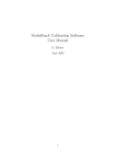
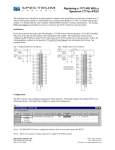
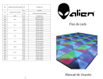
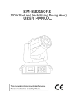
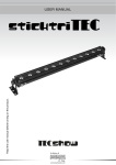
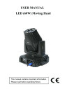
ATTENTION 1. DC 5V power input for equipment. Please only use the power adaptor provided in the package to operate the equipment. The allowed external voltage range of the adaptor is AC110V to 240V. HOE8321-32V Video Optical Transmission 3. In-door equipments, operating temperature and humidity should be controlled within the specified parameters, or else, the equipment may be damaged. 4. In case the dust come in, please protect the optical connectors with cover when the equipment do not connect with anything. Warning : Do not open the machine case. No spare parts are present inside the unit. Refer after-sale service, please contact with your dealer or our company directly. Digital Video Optical System 2. 12dB optical attenuation range. The total loss of optical fiber should be less than 12dB, otherwise, the receiver can not get the optical signals from the transmitter. User's Manual Manufacture Importer System Solution CHENGDU HALLEY OF OPTO-ELECTRONIC TECHNOLOGIES CO.,LTD http://www.halleycctv.com http://www.terzian.com.br CHENGDU HALLEY OF OPTO-ELECTRONIC TECHNOLOGIES CO., LTD Transmitter Receiver Optical Fiber CH8 CH10 CH11 CH12 CH13 CH14 CH15 CH16 CH17 CH18 CH19 CH20 CH21 CH22 CH23 CH24 CH25 CH26 CH27 CH28 CH29 CH30 CH31 CH32 CH4 CH5 CH6 CH7 Video Input CH3 CH2 CH25 CH26 CH27 CH28 CH29 CH30 CH31 CH32 Video Input Camera PTZ CH10 CH11 CH12 CH13 CH14 CH15 CH16 Video Input CH7 Do not open the machine case. No spare parts are present inside the unit. Refer after-sale service, please contact with your dealer or our company directly. CH17 CH18 CH19 CH20 CH21 CH22 CH23 CH24 Video Input PTZ CH8 Video Input CH6 Warning Camera PTZ Video Input CH5 Camera CH4 HOE8321-32V Transmitter; HOE8321-32V Receiver. Video Output Monitor Video Input CH3 PTZ CH2 The explanation given in this manual apply to the following models except the additional notice. Video Input Video Output Video Output Monitor Video Output Video Output Monitor Video Output Video Output Monitor Video Output Features High speed synchronous digital transmission technology Module construction design Camera PTZ Super optical dynamic range Power, Optical, Video, status indication Camera PTZ Non-electromagnetic interaction Safety Transmission for arduous electromagnetic environment Camera PTZ BNC video connector FC optical connector Video DC Restoration 1 Camera PTZ Video Output Monitor Video Output Video Output Monitor Video Output Video Output Monitor Video Output Video Output Monitor Video Output 10 The Application Camera AC Power Adapter (AC110V-240V) OPTICAL CH9 DC5V DC5V POWER CH1 Before operating the unit, please read this manual carefully and retain it for future reference. OPTICAL CH9 AC Power Adapter (AC110V-240V) POWER CH1 About this manual INSTALLTION ATTENTION Open the package and check the unit, Insure there is no anomalous voice from inside and did not be damaged. DC 5V power input for equipment. Please only use the power adaptor provided in the package to operate the equipment. The allowed external voltage range of the adaptor is AC110V to 240V. Power Connection Plug the power adaptor (provided) in AC110-240V power supply. The DC output of the adaptor connects respectively with the power input of the transmitter and the receiver . The working of green power indicator light of transmitter illustrates that the transmitter works normally. The working of yellow power indicator light of receiver illustrates that the receiver works normally. 12dB optical attenuation range. The total loss of optical fiber should be less than 12dB, otherwise, the receiver can not get the optical signals from the transmitter. In-door equipments, operating temperature and humidity should be controlled within the specified parameters, or else, the equipment may be damaged. In case the dust come in, please protect the optical connectors with cover when the equipment do not connect with anything. Optical Fiber Connection Connect the optical connectors of transmitter and receiver w ith a F C / PC patch cord. The b o t h w o r k i n g o f L i n k indicator lights of transmitter and receiver illustrate that the optical signals can be transmitted normally. Connect the video connector of transmitter to camera using the coaxial cable. Connect the video connector of receiver to monitor using the coaxial cable. INSTRUCTION The series are digital optical transmission system optimized for 32-channel video on one single optical fiber cable. 8bit/13.5MHz digital sample for video signal, digital optical access is the guarantee of high quality signal transmission. In addition, power, optical, video signal are easily inspected from the indicators on the front and rear panels. The series are high performance and reliability transmission system for long distance of video transmission. 9 2 Transmitter OPTICAL The Front Panel Transmitter Wavelength 1310nm Tx Transmitter Coupled Power >-6dBm into 9/125um fiber Rx Receiver Sensitivity <-20dBm for 65dB SNR Rx Receiver Saturation > 0dBm Optical Connector FC/PC Digital Video Optical System Video Signal Indicators Power Data Tx Optical Data Rx 1 2 3 4 5 6 7 Video Signal Indicators 8 9 10 11 12 13 14 15 16 Power Data Tx 17 18 19 20 21 22 23 24 Optical Data Rx 25 26 27 28 29 30 31 32 The Rear Panel PHYSICAL Optical port (FC/PC) OPTICAL POWER CH9 CH1 Power Input (DC5V) 3 CH10 CH11 CH12 CH13 CH14 CH15 CH16 CH2 CH3 CH4 CH5 CH6 CH7 CH8 CH25 CH26 CH27 CH28 CH29 CH30 CH31 CH32 CH17 CH18 CH19 CH20 CH21 CH22 CH23 CH24 Operating Temperature -35 - +75 Relative Humidity 0 - 95% non-condensing Power Requirements DC5V External Dimensions 445(L)×205(W)×45(H) Weight of Equipment 2500g/pc Video Input 1-32 ch 8 SPECIFICATIONS PORTS DEFINITION ELECTRICAL Video Input/Output Impedance Video INPUT Ports CH 1~CH 32 Optical Port (optical) FC/PC Power INPUT Port (power) DC 5V Power Supply 75Ω(unbalanced) Video Input/Output Level 1Vpp nominal Video Connector BNC Video Bandwidth 25Hz to 8MHz Video Distorion <0.5%DG,<0.5°DP Weighted Video SNR >62dB Power indicator: The normal working of power indicator shows that the input power supply is correct. The irregular working of power indicator shows that the input power supply is not correct or there are some problems with the inner circuit and the equipment need repair. Optical indicator: Indicate whether the optical signals is working correct or not. Video Signal indicators: Indicate the video status . Data TX indicator: Indicate the data output. Not use. Data RX indicator: Indicate the data input. Not use. Note: The LED indicators may not indicate the correct operating status without the right connection of fiber. 7 4 PORTS DEFINITION Receiver The Front Panel Digital Video Optical System Video Signal Indicators Power Data Tx Optical Data Rx 1 2 3 4 5 6 7 8 Power Data Tx Optical Data Rx 9 10 11 12 13 14 15 16 Video Signal Indicators 17 18 19 20 21 22 23 24 Video OUTPUT Ports CH 1~CH 32 Optical Port (optical) FC/PC Power INPUT Port (power) DC 5V power supply 25 26 27 28 29 30 31 32 The Rear Panel Power indicator: The normal working of power indicator shows that the input power supply is correct. The irregular working of power indicator shows that the input power supply is not correct or there are some problems with the inner circuit and the equipment need repair. Optical port (FC/PC) Optical indicator: Indicate whether the optical signals is working correct or not. OPTICAL CH9 CH10 CH11 CH12 CH13 CH14 CH15 CH16 CH25 CH26 CH27 CH28 CH29 CH30 CH31 CH32 Video Signal indicators: Indicate the video status . POWER CH1 Power Input (DC5V) CH2 CH3 CH4 CH5 CH6 CH7 CH8 CH17 CH18 CH19 CH20 CH21 CH22 CH23 CH24 Data TX indicator: Indicate the data output. Not use. Data RX indicator: Indicate the data input. Not use. Video Output 1-32 ch Note: The LED indicators may not indicate the correct operating status without the right connection of fiber. 5 6