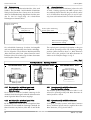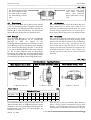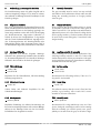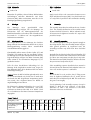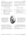
1
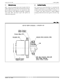
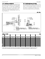
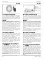
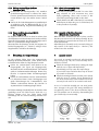
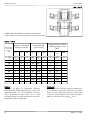
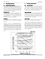
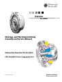
Präzision
Precision
Montage- und Wartungsanleitung
Assembly and Service Manual
Einbausätze Baureihe CSG-2A-(G)R-E
CSG-2A-(G)R-E Series Component Sets
Harmonic Drive AG
900147
01/2006
Harmonic Drive AG
CSG-2A-(G)R-E
Contents
Inhalt
1.
Schnittzeichnung
3
1.
Sectional Drawing
3
2.
2.1
2.2
2.3
2.4
2.5
2.6
2.7
2.7.1
2.7.2
Allgemeine Hinweise
Vorbemerkung
Herstellererklärung
Sicherheitshinweise
Garantie
Bezeichnung des Getriebes
Lagerung
Empfohlene Montagetoleranzen
Herstellung der Gehäuseteile
Vereinfachte Vermessung der Gehäuseteile/
Montagetoleranzen
4
4
4
4
5
5
5
5
6
2.
2.1
2.2
2.3
2.4
2.5
2.6
2.7
2.7.1
2.7.2
General Information
Preliminary notes
Declaration of conformity
Safety instructions
Warranty
Designation of the gear
Storage
Recommended tolerances for assembly
Manufacuring of the gear housing
Simplified measurement of the gear
housing/assembly tolerances
4
4
4
4
5
5
5
5
6
Anlieferungszustand
8
3.
Gear Conditions at Delivery
8
Schmierung
Fettmenge
Fettschmierung
Betriebsposition mit überwiegend senkrecht stehendem oder unten liegendem Wave Generator
4.2.2 Betriebsposition mit überwiegend oben liegendem Wave Generator
4.3 Ölschmierung
4.3.1 Ölmenge
8
8
10
4.
4.1
4.2
4.2.1
5.
5.1
5.2
5.2.1
5.2.2
5.2.3
5.2.4
3.
7
Lubrication
Grease quantity
Grease lubrication
Operation mainly with Wave Generator in vertical position or below
4.2.2 Operation mainly with Wave Generator above
4.3 Oil lubrication
4.3.1 Oil quantity
8
8
10
12
12
12
12
12
12
13
5.
5.1
5.2
5.2.1
5.2.2
5.2.3
5.2.4
12
12
12
12
12
12
13
Montage
Montageschritte
Montage des Circular Splines (CS)
Montage des Flexsplines (FS)
Montage des Wave Generators (WG) auf die
Antriebswelle
6.1.4 Prüfung vor dem Fügen des
Wave Generators (WG)
6.1.5 Fügen des Wave Generators (WG) in den
Flexspline (FS)
13
13
14
14
6.
6.1
6.1.1
6.1.2
6.1.3
7.
4.
4.1
4.2
4.2.1
Vorbereitung zur Montage des Getriebes
Allgemeine Hinweise
Montage-Hilfsstoffe
Flächendichtung
Schraubensicherung
Montagepaste
Klebstoffe
10
10
11
11
Assembly preparation
General information
Auxiliary materials for assembly
Surface sealing
Screw fixing
Assembly paste
Adhesives
10
10
11
11
13
13
14
14
15
Assembly
Assembly procedure
Assembly of the Circular Spline (CS)
Assembly of the Flexspline (FS)
Assembly of the Wave Generator (WG) to the
Input Shaft
6.1.4 Check before assembly of the
Wave Generator (WG)
6.1.5 Assembly of the Wave Generator (WG) into the
Flexspline (FS)
Überprüfung der richtigen Montage
15
7.
Assembly Control
15
8.
8.1
8.2
Wartung und Schmierung
Getriebe mit Fettschmierung
Getriebe mit Ölschmierung
17
17
19
8.
8.1
8.2
Maintenance and Lubrication
Grease lubrication
Oil lubrication
17
17
19
9.
Entsorgung/Gesundheitsschutz
20
9.
Disposal/Health Protection
20
10.
Haftungsausschluss
20
10.
Disclaimer of Liability
20
6.
6.1
6.1.1
6.1.2
6.1.3
2
7
14
15
14
15
15
900147 01/2006
Harmonic Drive AG
1.
Schnittzeichnung
Abb. 1 zeigt die Komponenten eines Standard CSG-2A(G)R-E Einbausatzes. Der Wave Generator kann mit integrierter Oldham Kupplung oder als sogenannter Solid
Wave Generator, ohne Oldham Kupplung, ausgeführt
sein. Beide Wave Generator Typen sind jeweils als
Halbschnitt dargestellt.
CSG-2A-(G)R-E
1.
Sectional Drawing
Fig. 1 shows the sectional drawing of a standard CSG2A-(G)R-E component set. The Wave Generator can be
designed either with integrated Oldham Coupling or as
a so-called Solid Wave Generator, without Oldham
Coupling. Both Wave Generator types are shown in Fig.
1.
Abb. / Fig. 1
900147 01/2006
3
Harmonic Drive AG
2.
Allgemeine Hinweise
CSG-2A-(G)R-E
2.
General Information
2.1
Preliminary notes
Dear Customer, you have acquired a very
reliable product, which has been manu factured with great care. Careful assem bly and the observation of the follo wing safety guidelines are necessary if
the products are to realize their high
technical performance.
2.1 Vorbemerkung
Sehr verehrter Kunde, Sie haben ein sehr zuverlässiges Produkt erworben, das mit großer Sorgfalt
gefertigt wurde. Zur Erzielung der vollen
Leistungsfähigkeit ist eine sorgfältige Montage
und die Beachtung der nachfolgenden
Hinweise erforderlich.
Sonderausführungen können in technischen
Details von den nachfolgenden Ausführungen
abweichen. Bei eventuellen Unklarheiten wird
dringend emp fohlen, unter Angabe vo n
Typbezeichnung
und
Teilenummer
bzw.
Seriennummer bei Harmonic Drive anzufragen.
Special versions may differ from those
described herein. If you have any
doubts whatsoever, we strongly advise
that you consult Harmonic Drive, giving
type, designation and part- or serial number.
2.2 Herstellererklärung
Harmonic Drive Getriebe sind Komponenten zum Einbau
in Maschinen im Sinne der Maschinenrichtlinie
89/392/EWG. Die Inbetriebnahme ist so lange untersagt, bis die Konformität des Endproduktes zu dieser
Richtlinie festgestellt ist.
2.2 Declaration of conformity
Harmonic Drive gears are components for installation in
machines as defined by the machine directive
89/392/EWG. Commissioning is prohibited until such
time as the end product has been proved to conform to
the provisions of this directive.
2.3
2.3
4
Sicherheitshinweise
Sämtliche Arbeiten am Getriebe sind im Stillstand
und ausschließlich von qualifiziertem Personal durchzuführen.
Das Getriebe darf nur zur bestimmungsgemäßen
Verwendung als Getriebe eingesetzt werden. Aus
sicherheitstechnischen und thermischen Gründen ist
der Betrieb nur bei vollständiger Verschraubung des
Getriebes mit dem Maschinengestell und der Last
e rlaubt. Bei nicht best i m m u n g s gemäßer Verwe n dung trägt allein der Benutzer das Risiko für Funktionsstörungen und Schäden. Der Hersteller wird von
der Haftung freigestellt.
Jede Änderung am Getriebe, die ohne unsere vorherige sch r i ftliche Genehmigung vo rge n o m m e n
wird, führt zum Verlust aller Garantieansprüche.
Der Hersteller der Maschine oder Anlage, der das
Getriebe in sein Produkt einbaut, ist verpflichtet,
durch geeignete technische Vorrichtungen zu verhindern, dass bei Funktionsstörungen des Getriebes
oder anderer Bauteile der Maschine bzw. Anlage in
der Nähe befindliche Personen in Gefahr geraten.
Die Getriebe sind in den Standardversionen für
Umgebungstemperaturen von 0 bis 40 °C ausgelegt. Während des Betriebs können an den Getrieben Oberflächentemperaturen von bis zu 80 °C auft reten. Es dürfen keine te mperaturempfindlichen
Teile, wie z.B. Elektrokabel oder elektronische Bauteile, anliegen oder befestigt werden. Ggf. sind Berührungsschutzmaßnahmen vorzusehen.
Safety instructions
Any work done on the gear must be carried out
while the gear is at a standstill.
The gear should not be put to improper use, or used
in a way not intended by its manufacturer. For reasons of safety and to avoid thermal problems the
gear should only be operated when already attached
completely to the machine housing and the load.
Should the user violate these guidelines, then he
alone, and not the manufacturer, must assume total
responsibility for any risks.
Modifications of any kind carried out on the gear
without our expressed prior written agreement nullifies all guarantee claims.
The machine or plant manufacturer who uses the
gear in his machines or plant must ensure that
should faults occur - irrespective of whether the fault
is caused by the gear or by other elements in the
machine or plant - the machine or plant will be
brought to a halt in such a way as to avoid complete or partial damage to the machine or plant, as well
as any danger to any person(s) near the machine or
plant.
The standard versions of the gears are developed for
ambient temperatures of 0 to 40 °C. During service
the gear surface temperature may reach 80 °C. No
temperature sensitive items such as wires or electronic components should be touching or attached to
the surface. If necessary, take precautions to prevent
contact.
900147 01/2006
Harmonic Drive AG
2.4 Garantie
Die Haftung des Herstellers für Mängel und daraus entstehender Folgen wird ausgeschlossen, wenn die Mängel
verursacht sind durch:
nicht bestimmungsgemäße Ve rwendung des
Getriebes
fehlerhafte Montage durch den Käufer oder Dritte
Betrieb ohne vollständige Verschraubung mit dem
Maschinengestell und der Last
fehlerhafte oder nachlässige Wartung
Verwendung nicht freigegebener Schmierstoffe
natürlichen Verschleiß
we i te re Ve rwendung nach dem Au ftreten vo n
Funktionsstörungen
nicht schriftlich vom Hersteller genehmigte Eingriffe
am Getriebe durch den Kunden.
CSG-2A-(G)R-E
2.4 Warranty
Liabilities resulting from the following actions will not be
covered by the manufacturer’s guarantee:
unsuitable or improper application of the gear
faulty assembly by the buyer or a third party
when the gear is operated without being attached
completely to the machine housing and the load
faulty or careless maintenance
utilisation of lubricants other than those which are
prescribed by the manufacturer
natural wear
continued use in spite of the appearance of defects
modifications of any kind carried out on the gear
without our expressed prior written agreement.
Please also refer to our delivery and payment conditions.
Bitte beachten Sie hierzu auch unsere
Lieferungs- und Zahlungsbedingungen.
2.5
Bezeichnung des
Getriebes
Bitte beachten Sie, dass die
Beste l l b e z e i chnung
des
G etriebes
auf
dem
Lieferschein in bestimmten
Fällen aus internen Gründen
von der Bezeichnung auf dem
Getriebe abweichen kann.
2.5 Designation of the gear
Please realize that due to internal reaso ns the ordering code given on the deli very note may not always be identical
with the label on the gear itself.
2.6 Lagerung
Wird das Getriebe nach der Auslieferung nicht gleich in
Betrieb genommen, so ist es in einem trockenen Raum
und in der Originalverpackung zu lagern. Die zulässige
Lagertemperatur beträgt -20 °C bis +60 °C.
2.6 Storage
If the gear is not put into service immediately on recei pt, it should be stored in a dry area in the original pack aging. The permissible storage temperature range is
-20 °C to +60 °C.
2.7 Empfohlene Montagetoleranzen
Die Genauigkeit des Getriebes wird u. a. von den
Toleranzen der kundenseitigen Gehäuseteile und der
Getriebeeingangswelle (Motorwelle) beeinflusst.
2.7 Recommended tolerances for assembly
The accuracy of the gear is among others dependent on
the customer´s housing tolerances and the input shaft
(motor shaft) tolerances.
Die eingangsseitigen (Motor-) Wellen und Flanschtoleranzen sollten der DIN 42955 genügen. Zur optimalen
Nutzung der hervo r r a genden Get r i e b e e i genschafte n ,
und beim Einsatz eines Solid Wave Generators (s. Abb.
12) empfehlen wir die Toleranzklasse R.
The input (motor) shaft and flange tolerances should
fulfil the DIN 42955 standard. To utilize the excellent
properties of the gears to their fullest extent we recom mended the use of the R tolerance class. We also recom mend the R tolerance class when the gear features a
solid Wave Generator, without Oldham Coupling (see
Fig. 12).
900147 01/2006
5
Harmonic Drive AG
CSG-2A-(G)R-E
2.7.1 Manufacturing of the gear housing
For the manufacturing of the gear housing we recom mend the dimensions and tolerances given in Fig. 2 and
Table 1. To achieve the given tolerances we recommend
that the motor- and gear-side centerings, see Fig. 2, sur face B and C, are manufactured at a single set-up.
All bore holes and thread holes must be chamfered.
2.7.1 Herstellung der Gehäuseteile
Wir empfehlen bei der Produktion der Gehäuseteile die
Einhaltung der Abmessungen und Toleranzen gemäß
Abb. 2 und Tabelle 1. Zur Erzielung der angegebenen
Toleranzen sollten die moto r- und getriebeseitigen
Zentrierflächen, siehe Abb. 2, Flächen B und C, unbedingt in einer einzigen Aufspannung gedreht werden.
Alle Bohrungen und Gewindebohrungen müssen mit
Fasen versehen sein.
Abb. / Fig. 2
Tabelle 1 / Table 1
[mm]
Größe
Size
a
b
c
d
e
f
g
14
17
20
25
32
40
45
50
58
65
0,011
0,012
0,013
0,014
0,016
0,016
0,017
0,018
0,020
0,023
0,008
0,011
0,014
0,018
0,022
0,025
0,028
0,030
0,032
0,035
0,015
0,018
0,019
0,022
0,022
0,024
0,027
0,030
0,032
0,035
0,011
0,015
0,017
0,024
0,026
0,026
0,027
0,028
0,031
0,034
0,011
0,015
0,017
0,024
0,026
0,026
0,027
0,028
0,031
0,034
0,017 (0,008)
0,020 (0,010)
0,020 (0,010)
0,024 (0,012)
0,024 (0,012)
0,032 (0,012)
0,032 (0,013)
0,032 (0,015)
0,032 (0,015)
0,032 (0,015)
0,030 (0,016)
0,034 (0,018)
0,044 (0,019)
0,047 (0,022)
0,050 (0,022)
0,063 (0,024)
0,065 (0,027)
0,066 (0,030)
0,068 (0,033)
0,070 (0,035)
() Die in Klammern angegebenen Werte sind empfohlene Toleranzen für Einbausätze mit Solid Wave Generator.
() The values in brackets are the recommended tolerances for Component Sets with a Solid Wave Generator.
6
900147 01/2006
Harmonic Drive AG
CSG-2A-(G)R-E
2.7.2 Vereinfachte Vermessung der
Gehäuseteile/Montagetoleranzen
Zur Prüfung der Montagetoleranzen hat sich die vereinfachte Vermessung gemäss Abb. 3 und Tab. 2 als praxisgerecht erwiesen. Bei den in Tab. 2 genannten Daten
w i rd vo r a u s gesetzt, dass bei der Fertigung der
Gehäusekomponenten die Regeln des deformationsarmen Spannens berücksichtigt werden (Segmentbacken),
und dass alle Ko mp o n e n ten mit angemessener
Wandstärke gefertigt werden.
2.7.2 Simplified measurement of the gear housing/
assembly tolerances
For the check of the assembly tolerances the simplified
measurement method according to Fig. 3 and Table 2
has been proved in praxis. With the data specified in
Table 2 it is presupposed that the housing components
are manufactured under consideration of the deformati on-poor clamping rules (segment grip), and that all com ponents are manufactured with appropriate wall thickn ess.
Wenn das Getriebe trotz der Einhaltung der Toleranzen
gemäss Abb. 3 und Tab. 2 nicht zufriedenstellend laufen
sollte, sind die Toleranzen gemäss Abb. 2 und Tab. 1 zu
prüfen.
If the gear should not run properly, although the design
meets the tolerances according to Fig. 3 and Table 2,
the tolerances given in Fig. 2 and Table 1 are to be con sidered.
Im Zweifelsfall ist die Einhaltung der Toleranzen gemäss
Abb. 2 und Tab. 1 ausschlaggebend.
In case of doubt the measurement according to Fig. 2
and Table 1 is decisive.
Abb. / Fig. 3
Tabelle 2 / Table 2
[mm]
Größe
Size
h
i
j
k
l
m
n
p
r
14
17
20
25
32
40
45
50
58
65
0,011
0,015
0,017
0,024
0,026
0,026
0,027
0,028
0,031
0,034
0,025
0,028
0,029
0,032
0,037
0,039
0,042
0,045
0,047
0,050
0,011
0,012
0,013
0,014
0,016
0,016
0,017
0,018
0,020
0,023
0,020
0,023
0,024
0,030
0,030
0,032
0,035
0,038
0,040
0,043
0,008
0,011
0,014
0,018
0,022
0,025
0,028
0,030
0,032
0,035
0,011
0,015
0,017
0,024
0,026
0,026
0,027
0,028
0,031
0,034
0,040 (0,026)
0,044 (0,028)
0,054 (0,029)
0,057 (0,032)
0,065 (0,037)
0,078 (0,039)
0,080 (0,042)
0,081 (0,045)
0,083 (0,048)
0,085 (0,050)
0,017 (0,008)
0,020 (0,010)
0,020 (0,010)
0,024 (0,012)
0,024 (0,012)
0,032 (0,012)
0,032 (0,013)
0,032 (0,015)
0,032 (0,015)
0,032 (0,015)
0,035 (0,021)
0,039 (0,023)
0,049 (0,024)
0,055 (0,030)
0,058 (0,030)
0,071 (0,032)
0,073 (0,035)
0,074 (0,038)
0,076 (0,041)
0,078 (0,043)
() Die in Klammern angegebenen Werte sind empfohlene Toleranzen für Einbausätze mit Solid Wave Generator.
() The values in brackets are the recommended tolerances for Component Sets with Solid Wave Generator.
900147 01/2006
7
Harmonic Drive AG
3.
Anlieferungszustand
CSG-2A-(G)R-E
3.
Gear Conditions at Delivery
Die Getriebe werden grundsätzlich gemäß den Angaben
auf der Bestätigungszeichnung ausgeliefert.
The gears are generally delivered according to the
dimensions indicated in the confirmation drawing.
Die drei Hauptkomponenten des Getriebes, Flexspline,
Wave Generator und Circular Spline, werden im Werk
zueinander ge p a a rt und entspre chend besch r i ftet.
Danach erfolgt die Konservierung mit Konservierungsöl
und die gemeinsame Verpackung der gepaarten Teile.
Bei Anlieferung mehre rer Einbausätze muss darauf
geachtet werden, dass die gepaarten Komponenten
nicht vertauscht werden. Bitte stellen Sie daher sicher,
dass die von Ihnen zusammengefügten Getriebekomponenten jeweils mit gleichen Endziffern beschriftet
sind.
The three basic components of the gear - the Flexspline,
Wave Generator and Circular Spline - are matched and
labelled in the factory. Depending on the product they
are either greased or prepared with preservation oil.
Then the individual components are assembled. If you
receive several units, please be careful not to mix the
matched components. This can be avoided by verifying
that the final numbers of the assembled gear compo nents are identical.
4.
4.
Schmierung
Lubrication
Die Getriebe sind bei Anlieferung standardmäßig mit
Konservierungsöl konserviert. Die Eigenschaften der
von Harmonic Drive zugelassenen Schmierfette und
Schmieröle werden durch die Vermischung mit dem
Konservierungsöl nicht verändert. Es ist daher nicht
erforderlich, das Konservierungsöl komplett von den
Getriebekomponenten zu entfernen. Allerdings müssen
die zu verschraubenden Flächen vor der Montage unbedingt entfettet werden, siehe auch Kap. 5.1.
At the time of delivery, the gears are conserved with pre servation oil. The characteristics of the lubricating grea se and oil types approved by Harmonic Drive are not
changed by mixing with the preservation oil. It is there fore not necessary to remove the preservation oil com pletely from the gear components. However, the mating
surfaces must be degreased before the assembly, see
also Chapter 5.1.
4.1 Fettmenge
Tabelle 3 beinhaltet die von Harmonic Drive für
Standardanwendungen empfohlenen Fettmengen.
Spezielle Anwe n d u n gen können ggf. spezielle
Schmierstoffe und -mengen erfordern. Im Zweifelsfall
wenden Sie sich bitte an die Harmonic Drive AG.
4.1 Grease quantity
Table 3 shows the grease quantities recommended by
Harmonic Drive for standard applications. Special appli cations may require special lubricants and lubricant
quantities. In case of doubt please ask Harmonic Drive
AG.
8
900147 01/2006
Harmonic Drive AG
CSG-2A-(G)R-E
Tabelle / Table 3
Fettschmierung / Grease lubrication
CSG-2A-(G)R
Baugröße/Size
Standard Fettmenge
Zusätzlich erforderliche Fettmenge bei
überwiegendem Einsatz mit oben
liegendem Wave Generator
Standard grease
quantity
Additionally required grease quantity
for operation with
Wave Generator above
Abmessungen
(s. Abb. 4)
Dimensions
(s. Fig. 4)
Standard Fett
s
ca. [mm]
Standard grease
Harmonic Drive
SK-2
ca. [g]
ca. [cm3]
ca. [g]
ca. [cm3]
14
5,5
6
3
3
3
17
10
11
4
5
4
20
16
18
9
9
4,5
25
40
44
13
14
5,5
32
60
66
22
24
7
40
130
143
44
49
9,5
45
180
198
59
65
11
50
260
286
72
79
12
58
360
396
117
129
13,5
65
440
484
141
155
15
Harmonic Drive
SK-1A
Tabelle / Table 4
Bestellbezeichnung
Verfügbare Gebinde
Available packages
Ordering code
[kg]
Spezialfett / Special grease SK-1A, SK-2
0,5; 2,5; 16
Spezialfett / Special grease 4BNo.2
0,5; 2; 16
Tabelle / Table 5
Ölschmierung / Oil lubrication
Freigegebene Schmieröle / Permittet oil lubricants
Hersteller
Manufacturer
Bezeichnung
Designation
900147 01/2006
Aral
BP
DEA
Degol Energol Falcon
BG 68 GR-XP 68 CLP 68
Esso
(Exxon)
Spartan
EP 68
Klüber
GEM
1-68
Mobil
Optimol
Mobil Optigear
Gear 626 BM 68
Shell
Texaco
Omala
Oil 68
Meropa
68
9
Harmonic Drive AG
CSG-2A-(G)R-E
4.2 Fettschmierung
Abb. 4 zeigt die zu schmierenden Bereiche, siehe auch
Tabelle 3. Das Fett 4BNo. 2 wird im Betrieb relativ dünnflüssig. Beim Einsatz dieses Fettes muss das Getriebe
daher wie für Ölschmierung abgedichtet sein. Bitte wenden Sie sich bei Fragen bzgl. der erfo rd e rlichen
Dichtungen an Harmonic Drive.
4.2 Grease Lubrication
Fig. 4 shows the areas to be lubricated, please also refer
to Table 3. During operation, the 4BNo.2 grease beco mes relatively liquid. Therefore the gear must be sealed
as for oil lubrication, when this grease is used. If requi red, please ask Harmonic Drive for further information.
Abb. / Fig. 4
Flexspline Verzahnung
Flexspline teeth
Flexspline Innenseite
Flexspline bore
Circular Spline Verzahnung
Circular Spline teeth
Wave Generator Kugellager
Wave Generator bearing
Die erforderliche Fettmenge ist neben der Baugröße
auch von der Betriebsposition des Getriebes abhängig.
Die im folgenden Text definierten Betriebspositionen
„Wave Generator oben“ bzw. „Wave Generator unten“
beziehen sich auf die relative Lage des Wave Generators
zum Flexspline Flansch, s. Abb. 5.
The required grease quantity is dependent on the gear
size and the operating position. The following operating
positions „Wave Generator above“ or „Wave Generator
below“ refer to the position of the Wave Generator in
relative to the Flexspline flange, see Fig. 5.
Abb. / Fig. 5
Betriebspositionen / Operating Positions
Wave Generator oben / above
Wave Generator senkrecht / vertical
Wave Generator
Wave Generator unten / below
Wave Generator
Wave Generator
4.2.1 Betriebsposition mit überwiegend senkrecht stehendem oder unten liegendem
Wave Generator
Die in Tabelle 3 definierte Standard Fettmenge ist für
den Betrieb mit überwiegend senkrecht stehendem oder
unten liegendem Wave Generator ausgelegt.
4.2.1 Operation mainly with Wave Generator
in vertical position or below
The standard grease quantity defined in Table 3 is cal culated for operating mainly with Wave Generator in
vertical position or below.
4.2.2 Betriebsposition mit überwiegend oben
liegendem Wave Generator
Bei überwiegendem Einsatz mit oben liegendem Wave
Generator ist eine zusätzliche Fettmenge oberhalb des
Wave Generators zu plazieren, siehe Abb. 6 und Tabelle
3.
4.2.2 Operation mainly with Wave Generator
above
If the gear is mainly operated with Wave Generator
above, additional grease must be supplied above the
Wave Generator, see Fig. 6 and Table 3.
10
900147 01/2006
Harmonic Drive AG
CSG-2A-(G)R-E
Abb. / Fig. 6
If the gear is used mainly
with Wave Generator
above, then additional
grease lubrication is neces sary.
Bei überwiegendem Einsatz
mit oben liegendem Wave
Generator ist diese zusätzliche Fettbefüllung erforderlich.
4.3 Ölschmierung
Wir empfehlen Mineralöl CLP 68 (ISO VG 68) nach DIN
51517 T.3. Von Harmonic Drive freigegebene Schmieröle
siehe Tabelle 5. Die Öltemperatur sollte während des
Betriebs 90 °C nicht überschreiten. Vor dem Einsatz
anderer Öle bitte Rücksprache mit Harmonic Drive.
4.3 Oil lubrication
We recommend mineral oil CLP 68 (ISO VG 68) accor ding to DIN 51517 T.3. Please refer to table 5 for oil
types that are confirmed by Harmonic Drive. The oil tem perature during operation must not exceed 90 °C.
Before using other oil types please ask Harmonic Drive.
4.3.1 Ölmenge
Die erfordeliche Ölmenge ist von der Konstruktion
abhängig. Au s s chlaggebend für die einzufüllende
Ö l m e n ge ist daher die Angabe in der
Zeichnung/Wartungsanleitung der Maschine. Die definierte Ölmenge ist genau einzuhalten. Bitte beachten
Sie in diesem Zusammenhang auch Abb. 7 und Tabelle
6. Die dort definierten Ölstände sind genau einzuhalten. Ein zu hoher Ölstand führt zu übermäßige r
Erwärmung und frühzeitigem Verschleiß durch thermische Zerstörung des Öles. Ein zu geringer Ölstand führt
zu frühzeitigem Verschleiß infolge Mangelschmierung.
4.3.1 Oil quantity
The required oil quantity is dependent on the design.
Therefore, the quantity specified in the drawing/service
manual of the machine is decisive for the oil quantity to
fill in. Please also refer to Fig. 7 and Table 6. The defi ned oil levels must be obeyed in any case. Too much oil
results in excessive heat production and early wear due
to thermal destruction of the oil. If the oil level is too
low, this may lead to early wear as a result of lubricant
deficiency.
Abb. / Fig. 7
Betriebspositionen / Operating Positions
Wave Generator oben / above
Wave Generator senkrecht / vertical
Wave Generator unten / below
B = Ölstand / Oil level
A= Ölstand / Oil level
B= Ölstand / Oil level
Tabelle/Table 6
[mm]
Ölstände / Oil Level
Baugröße / Size
14
17
20
25
32
40
45
50
58
65
A
B
10
2,5
12
3
14
3
17
5
24
7
31
9
35
10
38
12
44
13
50
15
Bei den Betriebspositionen „Wave Generator unten“ und
„Wave Generator oben“ ist der Ölstand besonders genau
einzuhalten, da bereits geringe Ölstandsänderungen die
Plansch ve rl u ste und damit den Wirku n g s grad des
Getriebes beeinflussen.
900147 01/2006
When the gear is to be used with the Wave Generator
above or below, special consideration must be given
because even small changes of the oil level affect the
churning losses and therefore the efficiency of the gear.
11
Harmonic Drive AG
5.
Vorbereitung zur Montage des Getriebes
CSG-2A-(G)R-E
5.
Assembly Preparation
Die Getriebemontage muss mit großer Sorgfalt und in
sauberer Umgebung erfolgen. Es ist darauf zu achten,
dass während der Montage keinerlei Fremdkörper in das
Getriebe gelangen.
The gear assembly must be carried out very carefully
and within a clean environment. Please make sure that
during the assembly procedure no foreign particles
enter the gear.
5.1 Allgemeine Hinweise
Um einen ausreichenden Reibungskoeffizienten zwischen den Oberflächen herzustellen, müssen die zu verschraubenden Flächen vor der Montage gereinigt, entfettet und getrocknet werden. Alle für die Übertragung
des Abtriebsmomentes einge s etzten Schrauben (s.
Tabelle 8) müssen der Festigkeitsklasse 12.9 genügen
und mit einem Drehmomentschlüssel angezogen werden. Sicherungselemente wie Unterlegscheiben oder
Zahnscheiben dürfen nicht eingesetzt werden. Falls in
der Konstruktion vorgesehen, sind Paßstifte einzusetzen.
5.1 General information
Clean, degrease and dry all mating surfaces to ensure
an adequate coefficient of friction. The values given in
Table 8 are valid for 12.9 quality screws which must be
tightened by means of a torque wrench. Locking devices
such as spring washers or toothed washers should not
be used. Please mount fixing pins, if considered in the
design drawing.
5.2 Montage-Hilfsstoffe
Wir empfehlen den Einsatz fo l gender Monta ge Hilfsstoffe oder gleichwertiger Produkte. Bitte beachten
Sie die Anwendungshinweise des Herstellers. MontageHilfsstoffe dürfen nicht in das Getriebe gelangen.
5.2 Auxiliary materials for assembly
For the assembly, we recommend the application of the
following auxiliary materials or the use of those with
similar characteristics. Please pay attention to the appli cation guidelines given by the manufacturer. Auxiliary
materials must not enter the gear.
5.2.1 Flächendichtung
5.2.1 Surface sealing
Loctite 5203
Loxeal 28-10
Loctite 5203
Loxeal 28-10
Empfohlen für alle Flanschflächen, falls keine O-RingDichtung vorgesehen ist.
Recommended for all mating surfaces, if the use of oring seals is not intended.
5.2.2 Schraubensicherung
5.2.2 Screw fixing
Loctite 243
Loctite 243
Schwer lösbar und dich tend. Emp fohlen für alle
Schraubenverbindungen.
This adhesive ensures that the screw is fixed and also
provides a good sealing effect. Loctite 243 is recom mended for all screw connections.
5.2.3 Montagepaste
5.2.3 Assembly paste
Klüber Q NB 50
Empfohlen für O-Ringe, die während der Montage aus
ihrer Nut herausspringen können. Alle anderen O-Ringe
sollten vor der Montage leicht mit dem im Getriebe
befindlichen Fett eingestrichen werden.
12
Klüber Q NB 50
Recommended for o-rings which may come out of the
groove during the assembly procedure. Before starting
with the assembly you should spread some grease
(which you can take from the gear) on all other o-rings.
900147 01/2006
Harmonic Drive AG
CSG-2A-(G)R-E
5.2.4 Adhesives
5.2.4 Klebstoffe
Loctite 638
Loctite 638
Einsetzbar für geklebte, schwer lösbare Wellen-NabenVerbindungen zwischen Motorwelle und Wave
Generator (Hub). Bitte nur benutzen, wenn dies in der
Bestätigungszeichnung vorgesehen ist.
Apply Loctite 638 to the connections between motor
shaft and Wave Generator (hub). You should make use
of it only if this is specified in the confirmation drawing.
6.
6.
Montage
Assembly
Die
Monta ge
muss
gru n d s ä t z l i ch
ohne
G ewa l te i nw i rkung erfolgen. Bei der Montage der
Einbausätze sind die Monta gevorschriften des
Maschinenherstellers zu beachten. Alle Schrauben sind
k re u z weise in 3 Schritten auf das vo rge s ch r i e b e n e
Drehmoment anzuziehen.
The assembly must take place without the use of undue
force. The assembly instructions of the machine manu facturer should be referred to. Unless otherwise noted,
all screws must be tightened crosswise in 3 steps to the
prescribed torque.
6.1 Montageschritte
Die Vorgehensweise bei der Montage des Getriebes
hängt stark von den konstruktiven Details ab. In dieser
Monta geanleitung werden daher aussch l i e ß l i ch
Standardinformationen gegeben.
6.1 Assembly procedure
The assembling method of the gear depends strongly on
the design details. Thus, this assembly manual only pro vides general guidelines. In exceptional cases, the
assembly procedure may differ from those described
herein.
Grundsätzlich sollten zuerst Circular Spline (CS) und
Flexspline (FS) montiert und fest verschraubt werden.
Die Montage dieser beiden Komponenten kann in beliebiger Reihenfolge erfolgen. Der Wave Generator (WG)
sollte zuletzt in die vormontierte Baugruppe FS/CS
geschoben werden.
Basically first the Circular Spline (CS) and Flexspline (FS)
should to be mounted and screwed down. The assemb ly of these two components can take place in any order.
The Wave Generator (WG) should be shifted at last into
the pre-mounted components FS/CS.
If the assembling sequence described above cannot be
observed please ask Harmonic Drive whether in the con crete case another sequence is admissible.
Falls die oben beschriebene Reihenfo l ge bei der
Montage nicht eingehalten werden kann, fragen Sie
bitte Harmonic Drive, ob im konkreten Fall eine andere
Reihenfolge zulässig ist.
Note:
Before the WG is set in position, the CS fixing screws
must be tightened. Otherwise the CS would deform
under the pre-load initiated by the WG. This could cause
the gear to run roughly.
Hinweis: Bevor der WG in Position gebracht wird, muss
der CS fest verschraubt sein, da sich der CS sonst unter
der durch den WG eingeleiteten Vorspannung verformen würde. Dies wiederum kö n n te im Betrieb zu
ungleichmäßigem Lauf führen.
For the planning of the assembly sequence it may be
helpful to know the max. diameter of the Wave
Generator. In Table 7 the diameters of the Wave
Generator main axes are indicated.
Zur Planung der Montagereihenfolge ist es ggf. hilfre i ch, den maximalen Durchmesser des Wave
Generators zu kennen, siehe Abb. 8. In Tabelle 7 sind
die ca. Durchmesser der Wave Generator Hauptachsen
angegeben.
[mm]
Tabelle/Table 7
14
17
20
25
32
ca. ∅ Wave Generator
- Hauptachse /
36
- Main axis
43
50
63
82 100 114 125 146 164
Baugröße / Size
900147 01/2006
40
45
50
58
65
13
Harmonic Drive AG
CSG-2A-(G)R-E
Abb. / Fig. 8
Abb. / Fig. 9
Ölbohrung
Oil bore
EKagrip® Scheibe
EKagrip® gasket
6.1.1 Montage des Circular Splines (CS)
Der CS darf während der Montage nicht deformiert werden. Es ist daher besonders wichtig, dass die kundenseitige Anschraubfläche des CS absolut eben ist und der
kundenseitige Zentrierbund weder Klemmkräfte noch
Spiel hervorruft.
Erläuterung:
Bereits ein geringfügig verformter CS kann zu ungleichmäßigem Lauf führen. Bei Verdacht auf Verformung des
CS sollte ge p r ü ft we rden, ob sich der CS in der
Zentrierung des Maschinengehäuses ohne Klemmen
drehen lässt. Bereits geringes Klemmen deutet darauf
hin, dass der CS möglicherweise unzulässig radial verformt wird. In diesem Fall müssen die Passungen vom
Maschinengehäuse und CS geprüft werden.
Bei Fettschmierung ist die CS Verzahnung gem. Kap. 4
zu schmieren. Die Montage ist unter Beachtung von
Kap. 5 und Tabelle 8 durchzuführen.
6.1.1 Assembly of the Circular Spline (CS)
The CS must not be bended during the assembly.
Therefore it is particularly important that the mounting
base of the CS is absolutely even and that the mounting
base centering causes neither clamping strength nor
radial clearance.
Explanation:
A slightly deformed CS can result in irregular running
characteristics. If a deformation of the CS is suspected it
should be verified whether the CS can rotate freely within its locating bore in the machine housing without any
friction. Even slight friction may be an indicator for a
possible radial deformation of the CS. In this case the
tolerances of the machine housing and the CS must be
checked.
For grease lubrication the CS teeth must be lubricated
in accordance with Chapter 4. The assembly is to be exe cuted considering Chapter 5 and Table 8.
6.1.2 Montage des Flexsplines (FS)
Den FS gem. Kap. 4 schmieren und unter Beachtung
von Kap. 5 und Tabelle 8 montieren. Dabei die mitgelieferte EKa grip Sch e i b e® zwischen FS Boden und
Abtriebselement platzieren, s. Abb. 9 und 10.
6.1.2 Assembly of the Flexspline (FS)
First lubricate the FS in accordance with Chapter 4.
Then assemble the FS considering Chapter 5 and Table
8. Thereby, place the EKagrip® gasket that is delivered
together with the component set, between FS bottom
and output element, cf. Fig. 9 and 10.
Bei Ölsch m i e rung und Betriebsposition "Wave
Generator oben" ist darauf zu achten, dass die Ölbohrung im Klemmring und in der EKa gr i p® S ch e i b e
deckungsgleich mit der Ölbohrung im Flexsplineboden
montiert wird, siehe auch Abb. 9.
6.1.3 Montage des Wave Generators (WG) auf die
Antriebswelle
Den WG vor oder nach der Monta ge auf die
Antriebswelle gem. Kap. 4 schmieren. Bei der Montage
ist das im Katalog/Bestätigungszeichnung angegebene
axiale Montagemaß einzuhalten.
Bei Verwendung eines Spannelementes die Schrauben
des Spannelementes in fünf Stufen und über Kreuz auf
das Anzugsmoment gemäß Zeichnung (alternativ:
Herstellerangabe) anziehen, siehe auch Abb. 12. Bei
Verwendung einer geklebten Wellen- Naben Verbindung
Kapitel 5 beachten.
14
For oil lubrication and operating position "Wave
Generator above" it must be considered that the oil
bore in the clamping ring and in the EKagrip® gasket is
mounted congruently with the oil bore in the Flexspline
diaphragm, see also Fig. 9.
6.1.3 Assembly of the Wave Generator (WG) to the
Input Shaft
Before or after the assembly to the input shaft the WG
is to be lubricated according to Chapter 4. During the
assembly the axial mounting position indicated on the
catalogue/confirmation drawing is to be considered.
When a clamping element is used please thighten the
clamping element screws crosswise and in five steps up
to the torque indicated on the drawing (alternatively:
manufacturer information), see also Fig. 12. When the
WG hub is glued to the input shaft please consider
Chapter 5.
900147 01/2006
Harmonic Drive AG
CSG-2A-(G)R-E
6.1.4 Prüfung vor dem Fügen des Wave
Generators (WG)
E n d ko n t rolle des Montagemaßes. Bei manch e n
Spannelementtypen kann es während des Anziehens der Spannelement Schrauben zu einem axialen
Versatz kommen. Ggf. den axialen Versatz "vorhalten".
Prüfen, ob alle Getriebekomponenten gemäß Kapitel
4 geschmiert sind. Bei Ölschmierung die in der
Maschinenzeichnung vorgeschriebene Ölmenge einfüllen.
6.1.4 Check before assembly of the
Wave Generator (WG)
Final check of position of the WG. For some clamping elements an axial movement may occur
during tightening. Please take account of this
effect when positioning the WG on the shaft.
Check whether the WG is lubricated in accordance
with Chapter 4. When the gear is oil lubricated, fill
in the prescribed oil quantity.
6.1.5 Fügen des Wave Generators (WG) in
den Flexspline (FS)
Bei Fügen des WGs in den FS ist darauf zu achten, dass
die Komponenten nicht verkantet sind. Durch paralleles
Fügen wird sichergestellt, dass die Verzahnungen von FS
und CS in symmetrischen Eingriff kommen.
Alternativ kann die Montage des WG bei langsam drehender Eingangswelle (n < 10 min-1) erfolgen. Diese
Vorgehensweise erleichtert die Montage.
6.1.5 Assembly of the Wave Generator
(WG) into the Flexspline (FS)
When the WG is assembled into the FS please consider
that the parts must not be tilt during assembly. By par allel assemby it is ensured that the teeth of FS and CS
mesh symmetrically.
Alternatively the assembly can be executed during slo wly rotation of the input shaft (n < 10 min-1). This
method eases the assembly.
7.
7.
Überprüfung der richtigen Montage
In sehr seltenen Fällen kann eine asymmet r i s che
Montage (Dedoidal) vorkommen, s. Abb. 10. Der korrekte Zusammenbau kann wie folgt überprüft werden:
Prüfen des Laufverhaltens durch Drehen an der
E i n ga n g s welle (bei Typen mit Einga n g s welle).
Alternativ: Drehen am Abtriebsflansch. Sehr deutlich
spürbare Drehmomentschwankungen können Ihre
Ursache in asymmet r i s chem Verzahnungseingriff
haben.
Prüfen des Laufverhaltens und der Stromaufnahme
bei drehendem Motor. Starke Schwingungen und
große Sch wa n ku n gen der St romaufnahme, oder
e rh ö h ter Leerl a u fst rom können Ihre Urs a che in
asymmetrischem Verzahnungseingriff haben.
Bei falscher Montage (Dedoidal) wird das Getriebe nicht
geschädigt, wenn der Fehler bereits durch die o. g.
Prüfung erkannt wird. Der Fehler kann durch
Demontage und eine erneute Montage behoben werden.
Abb. / Fig. 10
900147 01/2006
Assembly Control
Very rarely, an eccentric tooth mesh, called dedoidal,
may occur (see Fig. 10). The correct assembly can be
checked as follows:
Check the running behaviour by rotating the input
shaft (in case of types with input shaft).
Alternatively you may rotate the output flange.
If you notice torque variations these may be caused
by eccentric tooth mesh.
Check the running behaviour and the motor current
while the motor is rotating. Strong fluctuations in
the motor current and/or an excessive no-load current may be the result of an eccentric tooth mesh.
In case of a dedoidal assembly you can avoid perma nent damage to the gear if the wrong installation is
recognized by means of the above mentioned inspec tion. The problem can be solved by disassembling the
gear followed by a new assembly.
Abb. / Fig. 11
15
Harmonic Drive AG
CSG-2A-(G)R-E
Abb. / Fig. 12
Designbeispiele für Solid Wave Generator mit Spannelement.
Design examples for Solid Wave Generator with clamping element.
Tabelle / Table 8
HFUC-2A(G)R/
CSF-2A-(G)R
Baugröße/
Size
Anzahl der Schrauben
Number of screws
Schraubengröße
Size of screws
CS
FS
WG
CS
FS
WG
CS
FS
WG
14
8
6
2
M3
M4
M3
2
4,5
1,1
17
6
6
2
M3
M5
M3
2
9
1,1
20
6
8
0
M3
M5
-
2
9
-
25
6
8
0
M4
M6
-
4,5
15,3
-
32
6
8
0
M5
M8
-
9
37
-
40
6
8
0
M6
M10
-
15,3
74
-
45
6
8
0
M8
M12
-
37
128
-
50
6
8
0
M8
M14
-
37
205
-
58
6
8
0
M10
M14
-
74
205
-
65
6
8
0
M10
M16
-
74
319
-
Hinweis:
Tabelle 8 ist gültig für vo l l ständig entfettete
Anschlussflächen (Reibungskoeffizient µk = 0,15) und
Schraubenqualität 12.9. Sch a ft s chrauben mit met r ischem Regelgewinde nach DIN13 Teil 13 und
Kopfabmessungen von Zylinderschrauben ISO 4762,
unbehandelt, geölt, mit µges=0,12.
16
Anzugsmoment/Schraube
Clamping torque/screw
[Nm]
Please note:
Table 8 is valid for completely degreased mating surfa ces (coefficient of friction µk = 0.15) and 12.9 quality
screws. Set screws with metric thread according to DIN
13 Part 13 and head dimensions of screws according to
ISO 4762, non-treated, oiled, with µtot =0.12.
900147 01/2006
Harmonic Drive AG
8.
Wartung und Schmierung
CSG-2A-(G)R-E
8.
Maintenance and Lubrication
8.1 Getriebe mit Fettschmierung
Bei Fettschmierung ist für typische Anwendungen im allgemeinen kein Fettwechsel oder Nachschmieren erforderlich. Bei sehr hoher Belastung und Drehzahl kann
jedoch ein Fettwechsel oder Nachschmieren notwendig
werden. Bitte fragen Sie ggf. Ihren Vertriebspartner
nach weitergehenden Informationen.
8.1 Grease lubrication
When the gear is used in standard or light duty appli cations, a grease change is not necessary. However, a
grease change or a re-lubricaton may be necessary if the
gears are used for very high duty applications. Please
contact your sales engineer for further information.
Nachschmierung
Das Nachschmieren ist nur bei Anwendungen mit extremen Anforderungen sinnvoll. Zum Nachschmieren sollte
die Ko n struktion mit einem Schmiernippel und
Druckausgleichsventil o. ä. ausgerüstet sein, um das
Einfüllen von neuem Fett zu ermöglichen.
Grease re-lubrication
If the gear is used for very high duty applications then
the addition of new grease may be advisable. In this
case it is recommended that a grease nipple and a pres sure compensation valve (or similar device) be provided
to allow the addition of fresh grease.
Fettwechsel
Die Fettwechselintervalle werden durch den eingesetzten Fet t -Typ und die auftretenden Belastungen
bestimmt.
Grease change
The interval for a grease change is affected by the
applied grease type and by the load conditions.
In Abb. 13 sind die Fet t we chselintervalle in
Abhängigkeit von dem eingesetzten Fett-Typ und der
Fett-Temperatur gegeben. Dieses Diagramm ist gültig
bei Belastung des Getriebes mit Nenndrehzahl und
einem durchschnittlichen Drehmoment ≤ Nenndrehmoment. Abb. 13 zeigt, dass sich die Fettwechselintervalle
beim Einsatz des Fettes 4B No. 2 im Vergleich zu den
Fett-Typen SK-1A bzw. SK-2 ca. um den Faktor 6 verlängern.
In Fig. 13 the grease change intervals depending on the
applied grease type and the grease temperature are
given. The number of allowable revolutions of the input
shaft, which represents the grease change interval, can
be estimated as shown in the example. Using 4B No. 2
grease means that the grease change interval can be
extended approximately 6 times compared to that of
SK-1A or SK-2 grease.
Abb. / Fig. 13
900147 01/2006
17
Harmonic Drive AG
Beim Einsatz von 4BNo. 2 Fett sollte gemäß dem
Beispiel in Abb. 13 bei einer mittleren Fett-Temperatur
von 50°C ein Fet t we chsel nach etwa 3 x 10 9
Umdrehungen des Antriebselementes erfolgen.
Falls das durchschnittliche Getriebedrehmoment größer
als das Nenndrehmoment ist, ve rkürzt sich das
Fettwechselintervall nach folgender Gleichung:
CSG-2A-(G)R-E
The example in Fig. 13 shows that for 4B No. 2 grease
and a temperature of 50°C a grease change should take
place after ca. 3 x 10 9 revolutions of the input shaft.
If the average torque is higher than the rated torque the
grease change interval is reduced according to the fol lowing equation:
LGT= LGT n * (Tr /Tav)3
LGT= LGT n * (Tr /Tav)3
mit:
LGT
LGTn
= Anzahl Wave Generator Umdrehungen bis
zum Fettwechsel
= Anzahl Wave Generator Umdrehungen bis
Tr
zum Fettwechsel für Nenndrehmoment (aus
Abb. 13)
= Nenndrehmoment (aus Katalog)
Tav
= Durchschnittliches Drehmoment
with:
LGT
LGTn
Tr
Tav
= Number of Wave Generator revolutions until
grease change
= Number of Wave Generator revolutions until
grease change at rated torque (Fig. 13)
= Rated torque (cf. catalogue)
= Average torque (based on current load data)
(aus aktuellen Belastungsdaten)
Für den Fettwechsel sollte das alte
Fett mit einem sauberen Tuch vollständig aus dem Flexspline, den
Verzahnungen und aus dem Wave
Generator Kugellager entfernt werden. Alternativ kann das alte Fett
auch mit geeigneten Lösungsmitteln ausgewaschen werden.
For grease change the old grease should
be removed completely from the
Flexspline and the gear teeth by means
of a clean, lint-free cloth. The Wave
Generator ball bearing also needs to be
cleaned carefully by means of a cloth.
Alternatively the old grease can be was hed out also with suitable solvents.
Neues Fett sollte in den Flexspline, die
Verzahnungsbereiche des Circular Spline, des
Flexspline und das Wave Generator Kugellager
geschmiert werden, s. Abb. 4. Die erforderl i ch e
Standard-Fettmenge ist in Tabelle 3 angegeben.
Fresh grease should be applied generously to the
inside of the Flexspline, the teeth of the Circular
Spline and the Flexspline, and the Wave Generator ball
bearing, see Fig. 4. The required standard grease quan tity is given in Table 3.
Bei der anschliessenden Getriebemontage müssen alle
relevanten Kapitel dieser Montageanleitung beachtet
werden.
During the following gear assembly all relevant chap ters of this manual must be considered.
18
900147 01/2006
Harmonic Drive AG
8.2 Getriebe mit Ölschmierung
Der erste Ölwechsel sollte nach etwa 100
Betriebsstunden durchgeführt werden. Anschließende
Wechselintervalle hängen von der Belastung ab, sollten
jedoch in einem Zeitraum von etwa 1000 Betriebsstunden durchgeführt werden.
Zum Ölwechsel muss das alte Öl vollständig abgelassen
we rden und neues Öl eingefüllt we rden. We i tere
Informationen hierzu finden Sie im Kapitel 4.3.
Mögliche Schmieröle sind in Tabelle 5 angegeben. Die
M i s chung von Sch m i e r m i t teln mit unte rschiedlicher
Spezifikation ist grundsätzlich zu vermeiden.
900147 01/2006
CSG-2A-(G)R-E
8.2 Oil lubrication
The first oil change is necessary after 100 hours of ope ration. Subsequent oil change intervals depend on the
operating conditions, but should take place at intervals
of approximately 1000 running hours.
To change the oil, the used oil must be drained comple tely and fresh oil must be filled in. Further information
regarding oil lubrication can be found in chapter 4.3
and permitted oil types are given in Table 5. The mixtu re of lubricants of different specifications should gene rally be avoided.
19
Harmonic Drive AG
9.
Entsorgung/Gesundheitsschutz
Dieses Harmonic Drive Produkt beinhaltet
Schmierstoffe. Auf fachgerechte Entsorgung entsprechend der nationalen und örtlichen Vorschriften muss
daher geachtet werden.
Da Schmierstoffe (Fette und Öle) Gefahrstoffe sind, und
entsprechend den gültigen Gesundheitsschutzvorschriften behandelt werden sollten, empfehlen wir bei Bedarf das gültige Sicherheitsdatenblatt bei uns anzufordern.
CSG-2A-(G)R-E
9.
Disposal/Health Protection
This Harmonic Drive product includes lubrication. It is the refore necessary to dispose of the product correctly accor ding to national and local directives.
As lubricants (grease and oil) are hazardous substances,
they have to be handled according to the valid health pro tection directives. If necessary, we can provide our current
safety data sheet.
10.
10.
Disclaimer of Liability
Haftungsausschluss
Wir haben den Inhalt der
Druckschrift geprüft. Dennoch
können Abwe i ch u n gen nich t
ausgeschlossen werden, so
dass wir für die vollständige
Üb e re i n stimmung
keine
Gewähr übernehmen. Die
Angaben in dieser Druckschrift
werden re gelmäßig überprüft,
und notwendige Korrekturen sind
in den nachfolgenden Auflagen enthalten. Für Verbesserungsvorsch l ä ge
sind wir dankbar.
Every effort is made to provide accurate
and complete information. However, we
cannot guarantee that there will be no
errors. We make no claims, promises or
guarantees about the accuracy, comple teness, or adequacy of the contents of
this document and expressly disclaim lia bility for errors and commissions in the
contents. These are reviewed regularly and
any necessary corrections are included in
subsequent editions. Your suggestions for fur ther improvements are welcome.
Harmonic Drive AG
Hoenbergstraße 14
D-65555 Limburg/Lahn
P.O. Box 1652
D-65536 Limburg/Lahn
Germany
(
+49-6431/50 08-0
Fax
+49-6431/50 08-18
Internet www.harmonicdrive.de
Änderungen vorbehalten.
We reserve the right to make technical changes without prior notice.