1
BEI IDEACOD SAS
Espace Européen de l’Entreprise
9, rue de Copenhague
B.P. 70044 Schiltigheim
F 67013 Strasbourg Cedex
DEVICE NET USER MANUAL
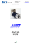
Absolute Rotary Encoder
with DEVICE NET Interface
MHM510-DNET-001
MHK515-DNET-001
User Manual
Tél
Fax
Mail
Web
:
:
:
:
+33 (0)3 88 20 80 80
+33 (0)3 88 20 87 87
[email protected]
www.bei-ideacod.com
BEI IDEACOD SAS
Espace Européen de l’Entreprise
9, rue de Copenhague
B.P. 70044 Schiltigheim
F 67013 Strasbourg Cedex
Tél
Fax
Mail
Web
:
:
:
:
+33 (0)3 88 20 80 80
+33 (0)3 88 20 87 87
[email protected]
www.bei-ideacod.com
DEVICE NET USER MANUAL
Alteration of Specifications reserved
Technical specifications, which are described
in this manual, are subject to change due to
our permanent strive to improve our products.
not be liable for any implied warranties of
merchantability and fitness for a particular
purpose or for any indirect, special, or consequential damages.
Disclaimer of Warranty
BEI IDEACOD makes no representations or
warranties, either express or implied, by or with
respect to anything in this manual. And shall
Page 2
UME-OCD-D2
Version 08/03
BEI IDEACOD SAS
Espace Européen de l’Entreprise
9, rue de Copenhague
B.P. 70044 Schiltigheim
F 67013 Strasbourg Cedex
Tél
Fax
Mail
Web
:
:
:
:
+33 (0)3 88 20 80 80
+33 (0)3 88 20 87 87
[email protected]
www.bei-ideacod.com
DEVICE NET USER MANUAL
1. Introduction
5
2. Data Transmission
5
2.1. The Object Dictionary ....................................5
3. Programmable Parameters
6
3.1. Encoder parameters ......................................6
3.1.2. Resolution per revolution ............................6
4. Operating Mode
8
4.1. Polled Mode.....................................................8
4.2. Change of State Mode..................................9
4.3. Saving Parameter ........................................ 11
5. Transmission of the actual position
11
6. Installation
12
6.1. Electrical connection .................................. 12
6.2. Setting of the baudrate .............................. 13
7. Power On
14
7.1. Operating Mode .......................................... 14
7.2. Programming ................................................ 14
7.2.1. Operating Parameter............................... 14
7.2.3. Total resolution........................................... 15
7.3 Configuration with DeviceNet Manager .. 18
7.4. Store Parameters .......................................... 23
8. Technical Data
25
8.1 Electrical Data ............................................... 25
8. 2 Mechanical Data......................................... 25
8.3 Minimum (mechanical) lifetime ................. 26
8. 4 Environmental Conditions........................... 26
9. Mechanical Drawings
27
10. Versions / Order Description
29
Version 05/04
UME-OCD-D2
Page 3
BEI IDEACOD SAS
Espace Européen de l’Entreprise
9, rue de Copenhague
B.P. 70044 Schiltigheim
F 67013 Strasbourg Cedex
Tél
Fax
Mail
Web
:
:
:
:
+33 (0)3 88 20 80 80
+33 (0)3 88 20 87 87
[email protected]
www.bei-ideacod.com
DEVICE NET USER MANUAL
1. Introduction
Absolute rotary encoders provide a definite
value for every possible position. All these values are reflected on one or more code discs.
The beams of infrared LEDs are sent through
code discs and detected by Opto-Arrays. The
output signals are electronically amplified and
the resulting value is transferred to the interface.
The absolute rotary encoder has a maximum
resolution of 65536 steps per revolution (16 Bit).
The Multi-Turn version can detect up to 16384
revolutions (14 Bit). Therefore the largest resulting resolution is 30 Bit = 1.073.741.824 steps.
The standard Single-Turn version has 12 Bit, the
standard Multi-Turn version 24 Bit.
Page 4
The integrated CAN-Bus interface of the absolute rotary encoder supports all of the DeviceNet functions. The following modes can
be programmed and enabled or disabled:
Polled Mode
Change of State
The protocol supports the programming of the
following additional functions:
Code sequence (Complement)
Resolution per revolution
Total resolution
Preset value
The general use of absolute rotary encoders
with DeviceNet interface is guaranteed.
UME-OCD-D2
Version 05/04
BEI IDEACOD SAS
Espace Européen de l’Entreprise
9, rue de Copenhague
B.P. 70044 Schiltigheim
F 67013 Strasbourg Cedex
Tél
Fax
Mail
Web
:
:
:
:
+33 (0)3 88 20 80 80
+33 (0)3 88 20 87 87
[email protected]
www.bei-ideacod.com
DEVICE NET USER MANUAL
2. Data Transmission
The data transmission in the DeviceNet network is realised by message telegrams. Basically, these telegrams can be divided into the
CAN-ID and 8 following bytes as shown in the
table below:
CAN-ID
Message Header
Message Body
11 Bit
1 Byte
7 Byte
2.1. The Object Dictionary
Instance Attribute of the Position Sensor Objects
Class Code:
23 hex
Attribute
ID
Access
Name
Data Type
Description
1 hex
Get
Number of Attributes
USINT
Number of supported Attributes
2 hex
Get
Attribute
Array of USINT
List of supported Attribute
3 hex
Get
Position value
DINT
current position
70 hex
Get
Set
/ Code sequence
Boolean
Controls the code sequence
clockwise or counterclockwise
71 hex
Get
Set
/
resolution per revolution
INT
resolution for one revolution
72 hex
Get
Set
/
total resolution
DINT
total measurable resolution
73 hex
Get
Set
/
preset value
DINT
setting a defined position value
Get / Set:
Version 05/04
: read, write
UME-OCD-D2
Page 5
BEI IDEACOD SAS
Espace Européen de l’Entreprise
9, rue de Copenhague
B.P. 70044 Schiltigheim
F 67013 Strasbourg Cedex
Tél
Fax
Mail
Web
:
:
:
:
+33 (0)3 88 20 80 80
+33 (0)3 88 20 87 87
[email protected]
www.bei-ideacod.com
DEVICE NET USER MANUAL
3. Programmable Parameters
3.1. Encoder parameters
3.1.1. Operating Parameter
The operating parameter can be used to select the code sequence.
Attribute ID
Default value
Value range
Data Type
0 b hex
1 hex
0 hex - 1hex
Boolean
The parameter code sequence (complement)
defines the counting direction of the process
value as seen on the shaft whether clockwise
or counter clockwise. The counting direction is
defined in the attribute 70 hex:
Bit 0
Drehrichtung
Ausgabecode
1
CW
Steigend
0
CCW
Fallend
3.1.2. Resolution per revolution
The parameter resolution per revolution is used
to program the encoder to set a desired
number of steps per revolution. Each value
between 1 and the maximum (see type shield)
can be realised
Attribute ID
Default value
Value range
Data Type
71 hex
(*)
0hex - 2000hex
Unsigned Integer16
(*) see type shield, Maximum resolution:
12/24 Bit Encoder: 1,000 hex (4096)
13/25 Bit Encoder: 2,000 hex (8192)
When the value is set larger than 4096 (8192
for a 13/25 Bit encoder), the process value of
the encoder will not be single stepped and
values will be skipped while rotating the shaft.
Page 6
So, it is recommended, to keep the measuring
steps per revolution below 4096 (8192) measuring steps.
UME-OCD-D2
Version 05/04
BEI IDEACOD SAS
Espace Européen de l’Entreprise
9, rue de Copenhague
B.P. 70044 Schiltigheim
F 67013 Strasbourg Cedex
Tél
Fax
Mail
Web
:
:
:
:
+33 (0)3 88 20 80 80
+33 (0)3 88 20 87 87
[email protected]
www.bei-ideacod.com
DEVICE NET USER MANUAL
3.1.3. Total resolution
This value is used to program the desired number of measuring steps over the total measuring range. This value must not exceed the total
resolution of the encoder with 24 bit =
16,777,216
steps
(25 bit = 33,554,432 steps). Please note the
value written on the type shield.
Attribute ID
Default value
Value range
Data Type
72 hex
(*)
0h - 2,000,000h
Unsigned Integer 32
(*) see type shield
Maximum total resolution
24 Bit Encoder: 1,000,000 hex
25 Bit Encoder: 2,000,000 hex
Attention:
The following formula letters will be used:
PGA Physical total resolution of the encoder (see type shield)
PAU
Physical resolution per revolution
(see type shield)
GA
Total resolution (customer parameter)
AU
Resolution per revolution (customer
parameter)
If the desired resolution per revolution is less
than the physical resolution per revolution of
the encoder, then the total resolution must be
entered as follows:
Total resolution
GA = PGA * AU / PAU, if AU < PAU
Example: Customer requirement: AU = 2048,
Encoder type shield: PGA=24 bit, PAU=12 bit
GA = 16777216 * 2048 / 4096
GA = 8388608
If the total resolution of the encoder is less than
the physical total resolution, the parameter
total resolution must be a multiple of the
physical total resolution:
k = PGA / GA
k = integer
3.1.4. Preset value
The preset value is the desired position value,
which should be reached at a certain physical
position of the axis. The position value of the
Attribute ID
Default
value
Value range
73 hex
0 hex
0hex range
Version 05/04
total
encoder is set to the desired process value by
the parameter preset. The preset value must
not exceed the parameter total measuring
units
Data Type
measuring
UME-OCD-D2
Unsigned Integer 32
Page 7
BEI IDEACOD SAS
Espace Européen de l’Entreprise
9, rue de Copenhague
B.P. 70044 Schiltigheim
F 67013 Strasbourg Cedex
Tél
Fax
Mail
Web
:
:
:
:
+33 (0)3 88 20 80 80
+33 (0)3 88 20 87 87
[email protected]
www.bei-ideacod.com
DEVICE NET USER MANUAL
4. Operating Mode
4.1. Polled Mode
For switching the polled mode on the following
telegrams are needed. Further it is assumed in
the
following example a master MAC ID of 0A hex
and a slave MAC ID of 03 hex.
Allocate Master / Slave Connection Set
1. Allocate Polling
Byte Offset
Bit 7
Bit 6
Bit 5
Bit 4
0
Frag [0]
XID
MAC ID
1
R/R [0]
Service [4B]
Bit 3
Bit 2
Bit 1
Bit 0
Class ID [03]
Instance ID [01]
Allocation Choice [03]
0
0
Allocator MAC ID
Example:
CAN-ID
Byte 0
Byte 1
Byte 2
Byte 3
Byte 4
Byte 5
41E
0A
4B
03
01
03
0A
1. Setting the Expected_packet_rate of the Explicit Message Connection on 0:
Example:
CAN-ID
Byte 0
Byte 1
Byte 2
Byte 3
Byte 4
Byte 5
Byte 6
41C
0A
10
05
01
09
00
00
1. Setting the Expected_packet_rate of the Polling Connection on 0:n:
Example:
CAN-ID
Byte 0
Byte 1
Byte 2
Byte 3
Byte 4
Byte 5
Byte 6
41C
0A
10
05
02
09
00
00
Page 8
UME-OCD-D2
Version 05/04
BEI IDEACOD SAS
Espace Européen de l’Entreprise
9, rue de Copenhague
B.P. 70044 Schiltigheim
F 67013 Strasbourg Cedex
Tél
Fax
Mail
Web
:
:
:
:
+33 (0)3 88 20 80 80
+33 (0)3 88 20 87 87
[email protected]
www.bei-ideacod.com
DEVICE NET USER MANUAL
Release Master / Slave Connection Set
Release Polling
Byte Offset
Bit 7
Bit 6
Bit 5
0
Frag [0]
XID
MAC ID
1
R/R [0]
Service [4C]
Bit 4
Bit 3
Bit 2
Bit 1
Bit 0
Class ID [03]
Instance ID [01]
Release Choice [03]
Example:
CAN-ID
41E
Byte 0
Byte 1
Byte 2
Byte 3
Byte 4
0A
4C
03
01
03
4.2. Change of State Mode
The absolute rotary encoder sends data, without any request from the host, when the actual process value is changing. No telegram
will occur when the position value is not
changing. This results in a reduced bus loading.
Allocate Master / Slave Connection Set
Allocate COS
Byte Offset
Bit 7
Bit 6
Bit 5
Bit 4
0
Frag [0]
XID
MAC ID
1
R/R [0]
Service [4B]
Bit 3
Bit 2
Bit 1
Bit 0
Class ID [03]
Instance ID [01]
Allocation Choice [51]
0
Version 05/04
0
Allocator MAC ID
UME-OCD-D2
Page 9
BEI IDEACOD SAS
Espace Européen de l’Entreprise
9, rue de Copenhague
B.P. 70044 Schiltigheim
F 67013 Strasbourg Cedex
Tél
Fax
Mail
Web
:
:
:
:
+33 (0)3 88 20 80 80
+33 (0)3 88 20 87 87
[email protected]
www.bei-ideacod.com
DEVICE NET USER MANUAL
Example:
CAN-ID
Byte 0
Byte 1
Byte 2
Byte 3
Byte 4
Byte 5
41E
0A
4B
03
01
51
0A
2. Setting Expected_packet_rate of the Explicit Message Connection on 0:
Example:
CAN-ID
Byte 0
Byte 1
Byte 2
Byte 3
Byte 4
Byte 5
Byte 6
41C
0A
10
05
01
09
00
00
3. Setting Expected_packet_rate of the Change of State Connection on 0:
Example:
CAN-ID
Byte 0
Byte 1
Byte 2
Byte 3
Byte 4
Byte 5
Byte 6
41C
0A
10
05
04
09
00
00
Release Master / Slave Connection Set
Release COS
Byte Offset
Bit 7
Bit 6
Bit 5
Bit 4
0
Frag [0]
XID
MAC ID
1
R/R [0]
Service [4C]
Bit 3
Bit 2
Bit 1
Bit 0
Class ID [03]
Instance ID [01]
Release Choice [51]
Example:
CAN-ID
Byte 0
Byte 1
Byte 2
Byte 3
Byte 4
41E
0A
4C
03
01
51
Page 10
UME-OCD-D2
Version 05/04
BEI IDEACOD SAS
Espace Européen de l’Entreprise
9, rue de Copenhague
B.P. 70044 Schiltigheim
F 67013 Strasbourg Cedex
Tél
Fax
Mail
Web
:
:
:
:
+33 (0)3 88 20 80 80
+33 (0)3 88 20 87 87
[email protected]
www.bei-ideacod.com
DEVICE NET USER MANUAL
4.3. Saving Parameter
The parameters of the absolute rotary encoder are saved in a non-volatile FLASH
memory. Because of a limited number of writing cycles (≈ 1,000), it is useful to transmit the
modified parameter in the first step only in the
RAM area. After adjusting and examination,
Byte
Offset
Bit 7
Bit 6
Bit 5
Bit 4
0
Frag [0]
XID
MAC ID
1
R/R [0]
Service [32]
those values can be saved in the FLASH memory. After successful saving of the parameter
the encoder sends his MAC-ID on the bus. To
get the process value a new allocation of the
slave is required.
Bit 3
Bit 2
Bit 1
Bit 0
Class ID [23]
Instance ID [01]
Example:
(MAC-ID Master: 0A hex, MAC-ID Slave: 03
hex)
CAN-ID Byte 0 Byte 1
Byte 2
Byte 3
41C
0A
32
23
01
5. Transmission of the actual position
The process value is transmitted according to
the following table.
CAN-ID
process value
11 Bit
Byte 0
Byte 1
Byte 2
Byte 3
27 to 20
215 to 28
223 to 216
231 to 224
Version 05/04
UME-OCD-D2
Page 11
BEI IDEACOD SAS
Espace Européen de l’Entreprise
9, rue de Copenhague
B.P. 70044 Schiltigheim
F 67013 Strasbourg Cedex
Tél
Fax
Mail
Web
:
:
:
:
+33 (0)3 88 20 80 80
+33 (0)3 88 20 87 87
[email protected]
www.bei-ideacod.com
DEVICE NET USER MANUAL
6. Installation
6.1. Electrical connection
The rotary encoder is connected by three
cables. The power supply is achieved with a
two-wire connection cable through one PG 9.
Each one of the twisted-pair and shielded bus
lines are guided in and out through two PG 9
on the right side (as seen on clamps)
There is a resistor provided in the connection
cap, which must be used as a line termination
on the last device
Resistor:
Last Device
RT
RT
ON
ON
-
G L
78
L
H
901
23
23
23
78
H G
901
901
78
+
Device X
456
456
456
Bd
x10
x1
RT
ON
The setting of the node number is achieved by
2 turn-switches in the connection cap. Possible
addresses lie between 0 and 63 whereby
every address can only be used once. 2 LEDs
DeviceNet Devices
BCD coded rotary switches
x1 Device adress 0...63
x10 Setting CAN-node number
xBd Setting of the baud-rate
Clamp
Description
⊥
+
-
Ground
CG
CAN Ground
CL
CAN Low
CH
CAN High
CG
CAN Ground
CL
CAN Low
CH
CAN High
Page 12
on the backside of the connection cap show
the operating status of the encoder.
24 V Supply voltage
0 V Supply voltage
UME-OCD-D2
Version 05/04
BEI IDEACOD SAS
Espace Européen de l’Entreprise
9, rue de Copenhague
B.P. 70044 Schiltigheim
F 67013 Strasbourg Cedex
Tél
Fax
Mail
Web
:
:
:
:
+33 (0)3 88 20 80 80
+33 (0)3 88 20 87 87
[email protected]
www.bei-ideacod.com
DEVICE NET USER MANUAL
6.2. Setting of the baudrate
Baudrate in kBit/s
BCD
coded
switches
125
0
250
1
500
2
125
3
reserved
4...9
Version 05/04
rotary
UME-OCD-D2
Page 13
BEI IDEACOD SAS
Espace Européen de l’Entreprise
9, rue de Copenhague
B.P. 70044 Schiltigheim
F 67013 Strasbourg Cedex
Tél
Fax
Mail
Web
:
:
:
:
+33 (0)3 88 20 80 80
+33 (0)3 88 20 87 87
[email protected]
www.bei-ideacod.com
DEVICE NET USER MANUAL
7. Power On
7.1. Operating Mode
After power on the absolute rotary encoder
sends two times his MAC ID telegram on the
bus.
7.2. Programming
If some parameters should not be modified
you can skip over this chapter.
format. In the examples, the CAN ID and MAC
ID are 0A (hex) and for the slave 03 (hex).
The following numbers are given in hexadecimal
The changeable values are written in an italics.
7.2.1. Operating Parameter
Master to absolute rotary encoder: Set-Parameter
CAN ID
MAC ID
41C
X:
Service
Class
Instance
Attribute
Code
ID
ID
ID
Byte 0
Byte1
Byte 2
Byte 3
Byte 4
0A
10
23
01
70
Data
Byte 5 Byte 6
X
-
Byte 7
-
1 hex for CW (Default)
0 hex for CCW
Absolute Rotary Encoder to Master:Confirmation
CAN ID
41B
MAC ID
Service Code
Byte 0
Byte 1
0A
90
7.2.2. Resolution per revolution
Master to Absolute Rotary Encoder:Set-Parameter
CAN ID
MAC ID
Service
Code
Class
ID
Instance
ID
Attribute
ID
Data
Byte 0
Byte 1
Byte 2
Byte 3
Byte 4
Byte 5
Byte 6
23
01
71
X
X
41C
0A
10
X: desired resolution per revolution
Page 14
UME-OCD-D2
Byte 7
-
Version 05/04
BEI IDEACOD SAS
Espace Européen de l’Entreprise
9, rue de Copenhague
B.P. 70044 Schiltigheim
F 67013 Strasbourg Cedex
Tél
Fax
Mail
Web
:
:
:
:
+33 (0)3 88 20 80 80
+33 (0)3 88 20 87 87
[email protected]
www.bei-ideacod.com
DEVICE NET USER MANUAL
Absolute rotary encoder to master:
CAN ID
41B
Confirmation
MAC ID
Service Code
Byte0
Byte1
0A
90
7.2.3. Total resolution
A fragmented transmission is needed, when
the total resolution must be sent to the encoder.
So here are more messages necessary.
Master to Absolute Rotary Encoder:Set-Parameter
CAN ID
41C
MAC ID
Fragment
Service
Code
Class
ID
Instance
ID
Attribute
ID
Byte 0
Byte 1
Byte 2
Byte 3
Byte 4
Byte 5
Byte 6
Byte 7
8A
00
10
23
01
72
X
X
Absolute Rotary Encoder to Master:Confirmation
CAN ID
41B
MAC ID
Byte0
Byte 1
Byte 2
8A
C0
00
Master to Absolute Rotary Encoder:Set-Parameter
CAN ID
MAC ID
Fragment
Byte 0
Byte 1
41C
8A
81
X: desired total resolution
Byte 2
Byte 3
Byte 4
Byte 5
Byte 6
Byte 7
X
X
-
-
-
-
Absolute Rotary Encoder to Master:Confirmation
CAN ID
41B
MAC ID
Byte0
Byte 1
Byte 2
8A
C1
00
Absolute Rotary Encoder to Master:Confirmation
CAN ID
41B
Version 08/03
MAC ID
Service Code
Byte0
Byte1
0A
90
UME-OCD-D2
Page 15
BEI IDEACOD SAS
Espace Européen de l’Entreprise
9, rue de Copenhague
B.P. 70044 Schiltigheim
F 67013 Strasbourg Cedex
Tél
Fax
Mail
Web
:
:
:
:
+33 (0)3 88 20 80 80
+33 (0)3 88 20 87 87
[email protected]
www.bei-ideacod.com
DEVICE NET USER MANUAL
7.2.4. Preset Value
Master to Absolute Rotary Encoder:Set-Parameter
CAN ID
41C
MAC ID
Fragment
Service
Code
Class
ID
Instance
ID
Attribute
ID
Byte 0
Byte 1
Byte 2
Byte 3
Byte 4
Byte 5
Byte 6
Byte 7
8A
00
10
23
01
73
X
X
X: desired preset value
Absolute Rotary Encoder to MasterConfirmation
CAN ID
41B
MAC ID
Byte0
Byte 1
Byte 2
8A
C0
00
Master to Absolute Rotary Encoder:Set-Parameter
CAN ID
MAC ID
Fragment
Byte 0
Byte 1
Byte 2
Byte 3
Byte 4
Byte 5
Byte 6
Byte 7
81
X
X
-
-
-
-
41C
8A
X: desired preset value
Absolute Rotary Encoder to MasterConfirmation
CAN ID
41B
MAC ID
Byte0
Byte 1
Byte 2
8A
C1
00
Absolute Rotary Encoder to Master:Confirmation
CAN ID
41B
Version 05/04
MAC ID
Service Code
Byte0
Byte1
0A
90
UME-OCD-D2
Page 16
BEI IDEACOD SAS
Espace Européen de l’Entreprise
9, rue de Copenhague
B.P. 70044 Schiltigheim
F 67013 Strasbourg Cedex
Tél
Fax
Mail
Web
:
:
:
:
+33 (0)3 88 20 80 80
+33 (0)3 88 20 87 87
[email protected]
www.bei-ideacod.com
DEVICE NET USER MANUAL
7.2.5. Parameter Saving
Master to Absolute Rotary Encoder:
CAN ID
Set-Parameter
MAC ID
Service Code
Class ID
Instance ID
Byte0
Byte1
Byte 2
Byte 3
32
23
01
If the transfer has been successful, the absolute rotary encoder responds after 3-4s with
the Duplicate MAC-ID. After that the master
must reallocate the slave.
If the transfer is not successful, an error message will be sent. The service code used to
save the parameter set is manufacturer specific.
Version 05/04
UME-OCD-D2
Page 17
BEI IDEACOD SAS
Espace Européen de l’Entreprise
9, rue de Copenhague
B.P. 70044 Schiltigheim
F 67013 Strasbourg Cedex
Tél
Fax
Mail
Web
:
:
:
:
+33 (0)3 88 20 80 80
+33 (0)3 88 20 87 87
[email protected]
www.bei-ideacod.com
DEVICE NET USER MANUAL
7.3 Configuration with DeviceNet Manager
Figure 1 EDS File
Encoder Installation in the Network
To configure the encoder in the network you
The EDS File contains information about device
specific parameters as well as possible operating modes of the encoder. With this file you
have a data sheet in an electronic format,
which can be used to configure the device in
the network, for example with DeviceNet
Manager from Allen Bradley.
To install the EDS (Electronic Data Sheet) file
you need a disc with this file. Further you must
choose from the menu the entry UTILITIES and
the sub menu INSTALL EDS FILES.
After that a window will open , where a drive
and the file is selected. Like shown in figure 1,
the file 1.EDS has been chosen. At the bottom
of the window more information is displayed
like manufacturer, product type and version
number.
have the following two possibilities:
1.
Offline
2.
Online
To create a network online it is necessary to
select the topic START ONLINE BUILD in the
menu UTILITIES. After that the network is
scanned and the encoder is automatically
shown in the main window, if an encoder is
installed. For the detailed proceedings please
look in the manual of the software DeviceNet
Manager.
If the network is built up offline you must create a new project. After configuration of network specific information such as baudrate
and description, a window with an empty
network and device list on the left side is
shown. Under the window device list you will
find the encoder in the area: GENERIC- Sensorsysteme. Use the mouse pointer to drag
After a successful installation the user can
and drop the symbol and move it to the line
assign a bitmap to the encoder. The file with
network. Additionally you must edit the device
the name AWC58xx.bmp is the right one.
description and the node number. Please be
careful to edit the same node number (MACID) in the software tool as configured in the
connection cap of the encoder.
Figure 2
Page 18
Selection of Bitmap File
UME-OCD-D2
Version 05/04
BEI IDEACOD SAS
Espace Européen de l’Entreprise
9, rue de Copenhague
B.P. 70044 Schiltigheim
F 67013 Strasbourg Cedex
Tél
Fax
Mail
Web
:
:
:
:
+33 (0)3 88 20 80 80
+33 (0)3 88 20 87 87
[email protected]
www.bei-ideacod.com
DEVICE NET USER MANUAL
Figure 3
Select encoder from device list
After successful execution of the before de-
When a double click is made on the encoder
scribed steps the network may look figure 4.
symbol a parameter window will open.
Version 05/04
UME-OCD-D2
Page 19
BEI IDEACOD SAS
Espace Européen de l’Entreprise
9, rue de Copenhague
B.P. 70044 Schiltigheim
F 67013 Strasbourg Cedex
Tél
Fax
Mail
Web
:
:
:
:
+33 (0)3 88 20 80 80
+33 (0)3 88 20 87 87
[email protected]
www.bei-ideacod.com
DEVICE NET USER MANUAL
Figure 4 Installation of network
This parameter masks makes it possible to edit
different parameters like monitoring the position value. The adjustable parameters are
marked with the number 1-4. The 5th entry
displays the actual position value, when the
function monitoring is activated with the button start monitor.
The button Load from Device makes it possible
to download the device specific parameter in
the configuration software. So it is very easy to
check the parameter or programming a replacement device with the same parameter.
Page 20
In the same way the control button Save to
Device transmits the edited parameters to the
encoder. Please notice that the transmitted
values are saved in the RAM area. By power
off and on you will loose these parameters.
After checking the parameters they can be
saved in the FLASH memory by selecting the
menu
entry
UTILITIES-BASIC
DEVICE
CONFIGURATION .
The entered values in the mask are taken from
the following figure. This prevent a mistake
through over taking wrong parameters.
UME-OCD-D2
Version 05/04
BEI IDEACOD SAS
Espace Européen de l’Entreprise
9, rue de Copenhague
B.P. 70044 Schiltigheim
F 67013 Strasbourg Cedex
Tél
Fax
Mail
Web
:
:
:
:
+33 (0)3 88 20 80 80
+33 (0)3 88 20 87 87
[email protected]
www.bei-ideacod.com
DEVICE NET USER MANUAL
Figure 5
Parameter mask
By a double click on each parameter a further
window opens to edit the value directly via
keyboard or scroll bar. A transmission of the
parameter into the RAM memory is secured
Figure 6
Version 05/04
with the Save to Device Button. A short description about each parameter is displayed
using the function Parameter Help.
Parameter mask
UME-OCD-D2
Page 21
BEI IDEACOD SAS
Espace Européen de l’Entreprise
9, rue de Copenhague
B.P. 70044 Schiltigheim
F 67013 Strasbourg Cedex
Tél
Fax
Mail
Web
:
:
:
:
+33 (0)3 88 20 80 80
+33 (0)3 88 20 87 87
[email protected]
www.bei-ideacod.com
DEVICE NET USER MANUAL
Saving Parameter by activated Scanner
((only necessary when firmware of Allen Bradley scanner is lower 4.001)
Picture 7
Scanner Mask
following described steps are not necessary
when the firmware of the AB scanner is 4.001
or higher. A update of the scanner is very
easy to execute. Please contact AB for further
information. When the parameter should be
transmitted from the DeviceNet Manager to
the encoder via the button SAVE to DEVICE,
the entry Active In Scanlist must be
deactivated. The mapped process values
could be placed further. After configuration
of parameters the encoder could be set
active in the scanlist again. If there are only
Page 22
encoders mentioned in the scanlist you could
alternately select all devices with SELECT ALL
and set then the state Active in Scanlist.
Another way is to select each encoder with
the mouse pointer.
If you don’t follow the description, the error
message - ‘Target device did not respond to
connection based request.’ - is possible from
DeviceNet manager and also in the scanner
display.
UME-OCD-D2
Version 05/04
BEI IDEACOD SAS
Espace Européen de l’Entreprise
9, rue de Copenhague
B.P. 70044 Schiltigheim
F 67013 Strasbourg Cedex
Tél
Fax
Mail
Web
:
:
:
:
+33 (0)3 88 20 80 80
+33 (0)3 88 20 87 87
[email protected]
www.bei-ideacod.com
DEVICE NET USER MANUAL
7.4. Store Parameters
For saving the encoder parameter into FLASH
memory you must select the menu item
UTILITIES and the entry BASIC DEVICE
CONFIGURATION. The selected node number
of the device must be entered into the field
Device-Node-Address as well as some other
parameters listed in the following figure 7. To
store the parameter please select the button
SAVE.
Version 05/04
UME-OCD-D2
Page 23
BEI IDEACOD SAS
Espace Européen de l’Entreprise
9, rue de Copenhague
B.P. 70044 Schiltigheim
F 67013 Strasbourg Cedex
Tél
Fax
Mail
Web
:
:
:
:
+33 (0)3 88 20 80 80
+33 (0)3 88 20 87 87
[email protected]
www.bei-ideacod.com
DEVICE NET USER MANUAL
Figure 7
Saving parameters in FLASH memory
Use the following values for the parameter:
Class
35
Instance & Attribute
Data Size
SAVE Service Code
Instance
Attribute Data:
Data:
1
Byte
50, Custom Service
1
0
Decimal
Version 05/04
UME-OCD-D2
Page 24
BEI IDEACOD SAS
Espace Européen de l’Entreprise
9, rue de Copenhague
B.P. 70044 Schiltigheim
F 67013 Strasbourg Cedex
Tél
Fax
Mail
Web
:
:
:
:
+33 (0)3 88 20 80 80
+33 (0)3 88 20 87 87
[email protected]
www.bei-ideacod.com
DEVICE NET USER MANUAL
8. Technical Data
8.1 Electrical Data
Interface
Transceiver according ISO/DIS 11898, up to 64 nodes
galvanically isolated by opto-couplers
Transmission rate
150 kBaud, 250 kBaud, 500kBaud
Device addressing
Adjustable by rotary switches in connection cap
Supply voltage
10 - 30 V DC (absolute limits)
Current consumption
max. 230 mA with 10 V DC, max. 100 mA with 24 V DC
Power consumption
max. 2.5 Watts
Step frequency LSB
800 kHz
Accuracy of division
± ½ LSB (12 bit), ± 2 LSB (16 bit)
EMC
Emitted interference:
Noise immunity:
Electrical lifetime
EN 61000-6-4
EN 61000-6-2
> 105 h
8. 2 Mechanical Data
Housing
Aluminum, optional stainless steel
Lifetime
Dependent on shaft version and shaft loading – refer to table
Max. shaft loading
Axial 40 N, radial 110 N
Inertia of rotor
≤ 30 gcm2
Friction torque
≤ 3 Ncm (without shaft sealing)
RPM (continuous operation)
Singleturn:
max. 12,000 RPM
Multiturn:
max. 6,000 RPM
Shock (EN 60068-2-27)
≤ 30 g (halfsine, 11 ms)
Permanent shock (EN 60028-2-
≤ 10 g (halfsine, 16 ms)
29)
Vibration (EN 60068-2-6)
≤ 10 g (10 Hz ... 1,000 Hz)
Weight (standard version)
Singleturn:
≈ 550 g
Multiturn:
≈ 600 g
Singleturn:
≈ 1,100 g
Multiturn:
≈ 1,200 g
Weight (stainless steel version)
Flange
Synchro (S)
Clamp (C)
Hollow shaft (B)
Shaft diameter
6 mm
10 mm
10 mm
15 mm
Shaft length
10 mm
20mm
20 mm
-
-
-
-
15 mm / 30 mm
hollow shaft depth min. / max.
Version 05/04
UME-OCD-D2
Page 25
BEI IDEACOD SAS
Espace Européen de l’Entreprise
9, rue de Copenhague
B.P. 70044 Schiltigheim
F 67013 Strasbourg Cedex
Tél
Fax
Mail
Web
:
:
:
:
+33 (0)3 88 20 80 80
+33 (0)3 88 20 87 87
[email protected]
www.bei-ideacod.com
DEVICE NET USER MANUAL
8.3 Minimum (mechanical) lifetime
Flange
Lifetime in 108 revolutions with Fa / Fr
40 N / 60 N
40 N / 80 N
40 N / 110 N
C10 (Clamp flange 10 x 20)
247
104
40
S10 (Synchro flange 10 x 20)
262
110
42
S6 (Synchro flange 6 x 10) without shaft sealing
822
347
133
S6 (Synchro flange 6 x 10) with shaft sealing: max. 20 N axial, 80 N radial
8. 4 Environmental Conditions
Operating temperature
– 40 .. +85°C
Storage temperature
- 40 .. + 85 °C
Humidity
98 % (without liquid state)
Protection class (EN 60529)
Casing side: IP 65
Shaft side: IP 64 (optional with shaft sealing: IP66)
Page 26
UME-OCD-D2
Version 05/04
BEI IDEACOD SAS
Espace Européen de l’Entreprise
9, rue de Copenhague
B.P. 70044 Schiltigheim
F 67013 Strasbourg Cedex
Tél
Fax
Mail
Web
:
:
:
:
+33 (0)3 88 20 80 80
+33 (0)3 88 20 87 87
[email protected]
www.bei-ideacod.com
DEVICE NET USER MANUAL
9. Mechanical Drawings
Synchro flange (S)
available in 2 versions
Synchro flange
d / mm
l / mm
Version S06
6f6
10
Version S10
10h8
20
Single-Turn=82, Multi-Turn=92
30
3xM4x6
3x
Ø42
Ø60
~32
l
63,5
Ø59 (Ø61)*
d
ø58
ø50 f7
0°
12
23
3
3
4
* Edelstahl / Stainless steel
Ø6,5-9
15
20
20
Schlüsselweite, wrench size=17
Clamp flange (C)
Single-Turn=82, Multi-Turn=92
30
30
3xM4x6
0°
12
3x
3xM3x6
Ø4
8
15°
Ø60
23
63,5
Ø36 f7
Ø10 h8
Ø53
Ø58
1
Ø59 (Ø61)*
18
3x12
0
°
10
~27
3
3
* Edelstahl / Stainless steel
15
Ø6,5-9
20
20
Schlüsselweite, wrench size=17
Version 05/04
UME-OCD-D2
Page 27
BEI IDEACOD SAS
Espace Européen de l’Entreprise
9, rue de Copenhague
B.P. 70044 Schiltigheim
F 67013 Strasbourg Cedex
Tél
Fax
Mail
Web
:
:
:
:
+33 (0)3 88 20 80 80
+33 (0)3 88 20 87 87
[email protected]
www.bei-ideacod.com
DEVICE NET USER MANUAL
Hollow shaft (B)
72
Ø63
Single-Turn=100 , Multi-Turn=112
3,3
20
Ø60
63,5
Ø15 F7
23
20°
Ø59 (Ø61)*
1,3
~32
Anlagekante
an Momentenstütze
(lay-on edge
torque support)
Ø3,2
* Edelstahl / Stainless steel
Max. W ** = 30
Min. W ** = 15
Ø6,5-9
15
20
** Welleneinstecktiefe (hollow shaft depth)
20
Schlüsselweite, wrench size=17
Mounting instructions
The clamp ring may only be tightened if the
shaft of the driving element is in the hollow
shaft.
The diameter of the hollow shaft can be
reduced to 12mm, 10 mm or 8 mm by using an
adapter (this reducing adapter can be
pushed into the hollow shaft).
Page 28
Allowed shaft movements of the drive element
are listed in the table.
axial
radial
static
± 0,3 mm
± 0,5 mm
dynamic
± 0,1 mm
± 0,2 mm
UME-OCD-D2
Version 05/04
BEI IDEACOD SAS
Espace Européen de l’Entreprise
9, rue de Copenhague
B.P. 70044 Schiltigheim
F 67013 Strasbourg Cedex
Tél
Fax
Mail
Web
:
:
:
:
+33 (0)3 88 20 80 80
+33 (0)3 88 20 87 87
[email protected]
www.bei-ideacod.com
DEVICE NET USER MANUAL
10. Versions / Order Description
Description
Type Key
Reference
Interface
Version
Code
Revolutions (Bits)
MHM5_
DeviceNet
Steps per revolution
(Bits)
Flange
Shaft diameter
Mechanical options
Connection
D2
D2
B1
B-
__
_ _-
_
__
_-
0CC
B1
Binary
B
Singleturn
Multiturn (4096 revolutions)
Multiturn (16384 revolutions)
4096
8192
65536
Clamp flange
Synchro flange
Hollow shaft
Square flange
10 mm
06 mm
15 mm (hollow shaft)
Without
Shaft sealing (IP66)
Stainless steel version
Customized
Connection Cap
00
12
14
12
13
16
C
S
B
Q
10
06
15
0
S
V
C
0CC
Standard = bold, further models on request
Ordering reference for a 10mm solid shaft absolute multiturn encoder :
MHM5 D2 B1 B 12 13 C 10 0 0CC : MHM510-DNET-001
Ordering reference for a 15mm blind shaft absolute multiturn encoder :
MHK5 D2 B1 B 12 13 B 15 0 0CC : MHK515-DNET-001
Version 05/04
UME-OCD-D2
Page 29
BEI IDEACOD SAS
Espace Européen de l’Entreprise
9, rue de Copenhague
B.P. 70044 Schiltigheim
F 67013 Strasbourg Cedex
Tél
Fax
Mail
Web
:
:
:
:
+33 (0)3 88 20 80 80
+33 (0)3 88 20 87 87
[email protected]
www.bei-ideacod.com
DEVICE NET USER MANUAL
Accessories and Documentation
Description
Type
Reducing adapter *
15 mm to 12 mm
RR12
Reducing adapter *
15 mm to 10 mm
RR10
Reducing adapter *
15 mm to 8 mm
RR8
*
only for hollow shaft
Page 30
UME-OCD-D2
Version 05/04