1
AZ9003/19
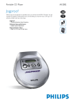
Portable compact disc player
ç
Volta ao Menu
PRODUCT FAMILY DORIS2 – PB2
TABLE OF CONTENTS
Technical specification ......................................................1-1
Connections and controls ..................................................1-2
Features ............................................................................1-3
Accessories .......................................................................1-3
Safety & Warnings .............................................................1-4
Service hints
Repair positions ............................................................2-1
Dismantling CD-door .....................................................2-1
CD-drive cleaning & lubrication .....................................2-2
CD-drive lens cleaning ..................................................2-2
Handling chip components............................................2-3
Service tools..................................................................2-3
Pin description of ICs ................................................3-1...3-4
Start-up procedure.............................................................3-5
Service Test Program................................................3-6...3-7
Blockdiagram .....................................................................3-8
Circuit diagrams
Part1 (signal processing) ..............................................4-1
Part2 (control) ...............................................................4-2
Part3 (supply) ................................................................4-3
Printed circuit board
Componentside view .....................................................4-4
Copperside view............................................................4-5
Exploded view ...................................................................5-1
Mechanical partslist ...........................................................5-1
Electrical partslist ..............................................................5-1
CLASS 1
LASER PRODUCT
Impresso no Brasil
08/2000
Sujeito a Modificações
Todos os Direitos Reservados
4806 725 27082
1-1
TECHNICAL SPECIFICATION
General
Shock resistance
Dimensions (WxHxD)
Weight without batteries
: 128x28x139mm
: 220g
: ≥2.5g
: ≥2.5g
: ≥2.0g
+X/-X direction
+Y/-Y direction
+Z/-Z direction
Power supply modes
Headphone out (measured with 16Ω load, DBB/ESP off)
DC-in socket
: 2.5-6.0V
Primary batteries (2xLR6)
: 1.6-3.6V
Rechargable batteries (AY3362) : 1.6-3.6V
Output power (THD=10%)
/17 version only
: 2x6mW (+1/-3dB)
all other versions
: 2x3mW (+1/-3dB)
Frequency response (1mW)
: 100Hz-20kHz within 6dB
S/N ratio (unwght)
: ≥78dB (81dB typ.)
S/N ratio (A-wght)
: ≥81dB (84dB typ.)
THD+N (1kHz, 1mW)
: ≤1% (0.2% typ.)
Channel crosstalk (1kHz, no load) : ≤-24dB (-44dB typ.)
Channel unbalance (-40dB)
: ≤5dB
Volume attenuation (1kHz)
: ≥60dB
Battery lifetime
BATTERY TYPE
ESP OFF
ESP ON
Primary batteries
2 x LR6
≥14h
(20h typ.)
≥14h
(17h typ.)
Rechargable batteries
AY3362 (1200mAh)
≥7h
(9.5h typ.)
≥7h
(9.5h typ.)
Dynamic Bass Boost DBB
Battery level detection
Frequency response
DBB STAGE
DETECTION LEVEL
63kHz
1kHz
10kHz
Primary batteries
Rechargable batteries
DBB 1
+6dB ± 2dB
0dB ± 2dB
0dB ± 2dB
Battery empty
1.8V
+100/-50mV
1.8V
+100/-50mV
DBB 2
+9dB ± 2dB
0dB ± 2dB
+5dB ± 2dB
Battery weak 1
battery empty level +
0.9V ± 100mV
battery empty level +
0.7V ± 100mV
Battery weak 2
battery empty level +
0.6V ± 100mV
battery empty level +
0.5V ± 100mV
Battery weak 3
battery empty level +
0.3V ± 100mV
battery empty level +
0.3V ± 100mV
Laser
Output power
Wavelength
: <5mW (3mW typ.)
: 780nm
Charge section (not on all versions)
Measurement setup
Charge current
Charge time for 80% AY3362
Max. charge time (µP controlled)
Temperature protection
: 250mA ±10%
: 4.0h nom.
: 7h
: 50°C ±5°C
Use Audio Signal disc SBC429
DUT
4822 397 30184
Low pass filter
S/N and distortion meter
L
22kHz
13th order
R
Current consumption
i.e. 4822 395 30204
DC-IN SUPPLY (4.5V)
BATT. SUPPLY (2.25V)
ESP OFF
ESP ON
ESP OFF
ESP ON
Play-mode
100mA typ.
100mA typ.
120mA typ.
120mA typ.
Jump-mode
220mA typ.
220mA typ.
300mA typ.
400mA typ.
OPERATION MODE
Stand-by
(excl. recharge)
CS 46 659
30mA typ.
100µA typ.
Level meter
i.e. Sennheiser UPM550
with FF-filter
i.e. Sound Technology ST1700B
1-2
CONNECTIONS AND CONTROLS
5
4
6
3
13
IG
D
L
A
IT
BB
D
2
PROGRA
M MOD
E
1
E SP
C
VD
4,5
7
8
9
O
FF
•
RE
SU
M
E
15
•H
OL
D
LIN
EO
UT/
OPE
N
14
VOL.
10
0
11
12
1 9 .....................stops CD play, clears a program or switches the
player off
2 DBB.................DIGITAL DYNAMIC BASS BOOST switches the
bass enhancement on and off
3 § ....................skips and searches CD tracks forwards
4 2; ...................switches the player on, starts or pauses CD play
5 ........................display
6 ∞ ....................skips and searches CD tracks backwards
7 PROGRAM .....programs tracks and reviews the program
8 MODE .............selects the different playing possibilities:
SHUFFLE, SHUFFLE REPEAT ALL, REPEAT, REPEAT ALL
and SCAN
9 RESUME.........stores the last position of a CD track played
HOLD ..............locks all buttons
OFF.................switches RESUME and HOLD off
0 LINE OUT/p ....3.5mm headphone socket, socket to connect the
player to another analogue audio input of an
additional appliance
! VOL E..........adjusts the volume
@ OPEN 2 ..........opens the CD lid
# 4.5V DC ..........socket for external power supply
$ ........................typeplate
% ESP.................Electronic Skip Protection ensures continuous
CD playback regardless of vibrations and shocks
TROUBLESHOOTING (excerpt from the Instruction For Use)
Problem
Possible cause
No power,
Batteries
playback does Batteries inserted incorrectly
not start
Batteries are empty
Contact pins are dirty
Mains adapter
Loose connection
nF d1SC
indication
no d1SC
indication
HoLd
indication
and/or
no reaction
to controls
In-car use
Cigarette lighter is not
powered when ignition is off
CD-RW (CD-R) is not
recorded properly
Solution
Insert the batteries
correctly
Change the batteries
Clean them with a cloth
Connect the adapter
securely
Switch on ignition or insert
batteries
Use FINALIZE on the
CD Recorder to complete
the recording
Replace or clean the CD
The CD is badly scratched
or dirty
CD is not or incorrectly inserted Insert a CD, label upwards
The laser lens is steamed up Wait until the lens has
cleared
HOLD is activated
Deactivate HOLD
Electrostatic discharge
Disconnect the set from
power supply or take out
the batteries for a few
seconds
Problem
Possible cause
CD skips tracks The CD is damaged or dirty
RESUME, SHUFFLE or PROGRAM
is active
No sound or
PAUSE is activated
bad sound
Loose, wrong or dirty
quality
connections
Volume is not adjusted
Malfunctions due to vicinity
of active mobile phones
Strong magnetic fields near
the player
In-car use
Cassette adapter is inserted
incorrectly
Temperature inside the car
is too high/low
Cigarette lighter socket
is dirty
Wrong playback direction of
the car cassette player’s
autoreverse feature
Solution
Replace or clean the CD
Switch RESUME, SHUFFLE
or PROGRAM off
Press 2;
Check and clean
connections
Adjust the volume
Keep the player away from
active mobile phones
Change the player’s
position or connections
Insert the cassette adapter
correctly
Let the player adjust to
the temperature
Clean the cigarette
lighter socket
Change the autoreverse
direction
CS 46 660
1-3
HOLD / RESUME FUNCTION
AZ9101
AZ9102
AZ9103
AZ9104
AZ9106
AZ9111
AZ9113
AZ9141
AZ9142
AZ9143
AZ9201
AZ9202
AZ9203
AZ9211
AZ9213
AZ9214
AZ9218
●
●
●
●
●
●
●
●
●
●
●
●
●
●
●
●
●
●
●
●
●
12s 12s 12s 12s 40s 40s 40s 40s 40s 40s 45s 40s 40s 40s 45s 45s 45s 45s 45s 45s 45s
–
4
4
4
4
8
8
8
8
8
8
8
8
8
8
8
8
8
8
8
8
8
●/● ●/● ●/● ●/● ●/● ●/● ●/● ●/● ●/● ●/● ●/● ●/● ●/● ●/● ●/● ●/● ●/● ●/● ●/● ●/● ●/● ●/●
DBB STAGES
ACOUSTIC FEEDBACK
2
2
2
2
2
2
2
2
2
2
2
2
2
2
2
2
2
2
2
2
2
2
●
●
●
●
●
●
●
●
●
●
●
●
●
●
●
●
●
●
●
●
●
●
99
99
99
99
99
99
99
99
99
99
99
99
99
99
99
99
99
99
99
99
99
99
●/● –/– ●/● –/–
–/–
–/–
–/–
–/–
–/–
–/–
–/–
–/–
–/–
–/–
–/–
–/– ●/● –/–
–/–
–/–
–/–
–/–
–
PROGRAM MEMORY
RECHARGE NiCd / NiMH
CORD REMOTE CONTROL
AZ9011
–
AZ9003
●
ELECTRONIC SKIP PROTECTION
ESP DRAM SIZE [Mbit]
AZ9002
CD-RW COMPATIBILITY
AZ9001
FEATURES OF CD-PORTABLE
PRODUCT FAMILY “DORIS2 – PB2”
AZ7902
FEATURES
LCD BACKLIGHT
LINE / OPT. DIGITAL OUTPUT
–
–
–
–
–
–
–
–
–
–
–
–
–
–
–
–
–
–
–
–
●
–
–
–
–
–
–
–
–
–
–
–
–
–
–
–
–
–
–
–
–
–
–
–/–
–/–
–/–
–/–
–/–
–/–
–/–
–/–
–/–
–/–
–/–
–/–
–/–
–/–
–/–
–/–
–/–
–/–
–/–
–/–
–/–
–/–
AY3170/00 AC/DC Adaptor
AY3170/02 AC/DC Adaptor
AY3170/05 AC/DC Adaptor
AY3170/09 AC/DC Adaptor
AY3170/10 AC/DC Adaptor
AY3170/12 AC/DC Adaptor
AY3170/13A AC/DC Adaptor
AY3170/17 AC/DC Adaptor
AY3266/00 Pouch (Neoprene)
4822 219 10617
4822 219 10676
4822 219 10672
4822 219 10679
4822 219 10681
4822 219 10671
3140 118 31590
4822 219 10616
12NC follows
AY3362/00 Rechargable Batt. NiMH 3103 308 84120
4822 397 10059
AY3501/00 Car Adaptor Cassette
4822 219 10033
AY3545/00 Car DC/DC Converter
4822 242 11004
AY3677/00 Earphone (L-plug)
4822 242 11021
AY3677/00S Earphone (straight plug)
4822 242 11003
AY3682/00 Headphone (L-plug)
12NC follows
AY3767/00 Cord Remote Control
AY3464 HiFi Cord (3.5mm L-plug→cinch) 4822 320 11881
X...supplied with the set, O...optional available
CS 46 661
AZ9218
AZ9203
AZ9211
AZ9213
AZ9214
AZ9106
AZ9111
AZ9113
AZ9141
AZ9142
AZ9143
AZ9201
AZ9202
AZ9011
AZ9101
AZ9102
AZ9103
AZ9104
AZ9003
AZ9002
/00
/00
/00z
/05
/11
/17
/00
/05
/01
/09
/10
/18
/19
/00
/17
/17
/17
/16
/17
/17
/17
/17
/17
/17
/17
/00
/00
/05
/11
/13
/10
/00
/17
/00
/17
/17
ACCESSORIES FOR CD-PORTABLE
PRODUCT FAMILY “DORIS2 – PB2”
AZ7902
AZ9001
ACCESSORIES
X X X
X
X
X X
X
X
X
X
X
X
X
X
X
X
X
X
X
X
X
X
X
O O O O O O O
O O O O O O O
X X X X X
X
X
X X X
X X X X X X X
X
X
O X X X X X O O O X X X O O X X X X O O
O X X X X X O O O X X X O O X X X X O O
X X X X X X X
X
X X
X X X
X X X X X X X
X
X
O
O
X
X X
X X
X X
X
O O X O X O O X
O O X O X O O X
X X X X
X
X
X
X
X
O O O O O O O O O O O O O O O O O O O O O O O O O O O O O O O O O O O O
1-4
SAFETY & WARNINGS
©
ESD
WARNING
All ICs and many other semiconductors are susceptible to
electrostatic discharges (ESD). Careless handling during
repair can reduce life drastically.
When repairing, make sure that you are connected with the
same potential as the mass of the set via a wristband with
resistance. Keep components and tools at this potential.
f
ATTENTION
Tous les IC et beaucoup d´autres semi-conducteurs sont
sensibles aux décharges statiques (ESD). Leur longévite
pourrait être considérablement écourtée par le fait qu´aucune
précaution nést prise à leur manipulation.
Lors de réparations, s´assurer de bien être relié au même
potentiel que la masse de l´appareil et enfileer le bracelet
serti d´une résistance de sécurité.
Veiller à ce que les composants ainsi que les outils que l´on
utilise soient également à ce potentiel.
©
ñ
WAARSCHUWING
Alle IC´s en vele andere halfgeleiders zijn gevoelig voor
electrostatische ontladingen (ESD).
Onzorgvuldig behandelen tijdens reparatie kan de levensduur
drastisch doen vermindern. Zorg ervoor dat u tijdens reparatie
via een polsband met weerstand verbonden bent met hetzelfde
potentiaal als de massa van het apparaat.
Houd componenten en hulpmiddelen ook op ditzelfde potentiaal.
d
i
WARNUNG
AVVERTIMENTO
Tutti IC e parecchi semi-conduttori sono sensibili alle scariche
Alle ICs und viele andere Halbleiter sind empfindlich
statiche (ESD).
gegenüber elektrostatischen Entladungen (ESD).
La loro longevità potrebbe essere fortemente ridatta in caso di
Unsorgfältige Behandlung im Reparaturfall kann die
non osservazione della più grande cauzione alla loro
Lebensdauer drastisch reduzieren.
manipolazione. Durante le riparationi occorre quindi essere
Sorgen Sie dafür, daß Sie im Reparaturfall über ein Puls- collegato allo stesso potenziale che quello della massa
armband mit Widerstand mit dem Massepotential des
delápparecchio tramite un braccialetto a resistenza.
Gerätes verbunden sind.
Assicurarsi che i componenti e anche gli utensili con quali si
Halten Sie Bauteile und Hilfsmittel ebenfalls auf diesem
lavora siano anche a questo potenziale.
Potential.
AVAILABLE ESD PROTECTION EQUIPMENT :
anti-static table mat
large 1200x650x1.25mm
small 600x650x1.25mm
4822 466 10953
4822 466 10958
anti-static wristband
4822 395 10223
connection box (3 press stud connections, 1MΩ)
4822 320 11307
extendible cable (2m, 2MΩ, to connect wristband to connection box) 4822 320 11305
connecting cable (3m, 2MΩ, to connect table mat to connection box) 4822 320 11306
earth cable (1MΩ, to connect any product to mat or to connection box) 4822 320 11308
KIT ESD3 (combining all 6 prior products - small table mat)
4822 310 10671
wristband tester
4822 344 13999
SAFETY
©
ñ
Safety regulations require that the set be restored to its
original condition and that parts which are identical with
those specified be used.
Safety components are marked by the symbol
Veiligheidsbepalingen vereisen, dat het apparaat in zijn
oorspronkeliijke toestand wordt teruggebracht en dat
onderdelen, identiek aan de gespecificeerde, worden toegepast.
De Veiligheidsonderdelen zijn aangeduid met het symbool
f
i
Les normes de sécurité exigent que l`appareil soit remis
à l`état d`origine et que soient utilisées les pièces de
rechange identiques à celles spécifiées.
Les composants de sécurité sont marqués
Le norme di sicurezza estigono che l´apparecchio venga
rimesso nelle condizioni originali e che siano utilizzati i
pezzi di ricambiago identici a quelli specificati.
Componenty di sicurezza sono marcati con
©
DANGER: Invisible laser radiation when open.
AVOID DIRECT EXPOSURE TO BEAM.
d
Bei jeder Reparatur sind die geltenden Sicherheitsvorschriften zu beachten. Der Originalzustand des Gerätes
darf nicht verändert werden. Für Reparaturen sind Originalersatzteile zu verwenden.
Sicherheitsbauteile sind durch das Symbol
markiert.
CLASS 1
LASER PRODUCT
s Varning !
∂ Advarsel !
ß Varoitus !
Osynlig laserstrålning när apparaten är öppnad och
spärren är urkopplad. Betrakta ej strålen.
Usynlig laserstråling ved åbning når sikkerhedsafbrydere
er ude af funktion. Undgå udsaettelse for stråling.
Avatussa laitteessa ja suojalukituksen ohitettaessa olet alttiina
näkymättömälle laserisäteilylle. Älä katso säteeseen !
©
f
After servicing and before returning the set to customer
perform a leakage current measurement test from all
exposed metal parts to earth ground, to assure no
shock hazard exists.
The leakage current must not exceed 0.5mA.
"Pour votre sécurite, ces documents doivent être utilisés par
des spécialistes agréés, seuls habilités à réparer votre
appareil en panne".
CS 46 662
2-1
SERVICE HINTS
REPAIR POSITION COPPERSIDE
REPAIR POSITION COMPONENTSIDE
To get access to the copperside of the
printed board assembly proceed as follows:
To get access to the componentside of the
printed board assembly proceed as follows:
1.
2.
3.
4.
1.
2.
3.
4.
5.
Remove the bottom screws (6x)
Lift the bottom-cabinet
Supply the unit via external DC-socket
Take care that the door switch is closed during
measurements
Remove the bottom screws (6x)
Open the CD-door
Lift the top-cabinet and put it backwards on the table
Supply the unit via the external DC-socket
Take care that the door switch is closed during
measurements
DISMANTLING THE CD-DOOR
To dismantle the CD-door proceed as follows:
1. Disconnect the membrane keyboard
(flex-foil connector on copperside of printed board)
2. Smoothly bend the bridge of the cabinet downwards as
shown in 1. Take care not to touch the lens
3. Smoothly pull out the right hinge of the CD-door as
shown in 2.
4. Lift the CD-door
CS 46 663
Remark: Do not use screwdrivers or tools like that.
Sharp edges could damage hinge or cabinet part.
2-2
VAM2103/08 – DRIVE CLEANING & LUBRICATION
Lubrication of the CD-drive is only necessary in case
of symptom “skipping tracks”.
The reason can be dirt which sticks to the grease or
the grease is getting aged.
Use an acid-free synthetic grease – i.e. “Tribol 9890-2” or
equivalent.
Before greasing the mechanism first remove the old grease
from the mechanism. Use a cotton swab dipped in alcohol to
clean the mechanism.
VAM2103/08 – LENS CLEANING
Before touching the lens it is advised to clean the
surface of the lens by blowing clean air over it in
order to avoid that little particles make scratches on
the lens.
Because the material of the lens is synthetic and coated
with a special anti-reflectivity layer, cleaning must be done
with a non-aggressive cleaning fluid. It is advised to use
“KODAK LENS CLEANER CAT 176 71 36”, available in
normal photo shops.
The actuator is a very precise mechanical component and
may not be damaged in order to guarantee its full function. It
is advised to clean the lens gently (don’t press too hard)
with a soft and clean cotton bud moistened with the special
lens cleaner.
The direction of cleaning must be in the way as indicated in
the picture below.
Cleaning the mechanism
1. Clean the lower and upper sledge guidance plane
(optical pick-up).
2. Clean the spindle shaft.
3. Clean the area between the worm gear, idler wheel and
clamping spring.
Lubricating the mechanism
1. Put one dot of grease onto the upper sledge guidance
plane on each side of the sledge. Move the sledge to the
inner and outer position to spread the grease.
Put one dot of grease onto the lower sledge guidance
plane on each side of the sledge. Move the sledge to the
inner and outer position to spread the grease.
2. Put one dot of grease onto the spindle shaft on both sides
of the sledge. Move the sledge to the inner and outer
position to spread the grease.
3. Put one dot of grease between the worm gear and the
clamping spring.
CS 46 664
2-3
HANDLING CHIP COMPONENTS
SERVICE TOOLS
Audio signal disc SBC429
Playability test disc SBC444
Test disc 5 (disc without errors) + Test disc 5A (disc with dropout errors,
black spots and fingerprints) SBC426/SBC426A
4822 397 30184
4822 397 30245
4822 397 30096
ESD PROTECTION EQUIPMENT
Anti-static table mat large 1200x650x1.25mm
small 600x650x1.25mm
Anti-static wristband
Connection box (3 press stud connections, 1MΩ)
Extendible cable (2m, 2MΩ, to connect wristband to connection box)
Connecting cable (3m, 2MΩ, to connect table mat to connection box)
Earth cable (1MΩ, to connect any product to mat or to connection box)
KIT ESD3 (combining all 6 prior products - small table mat)
Wristband tester
CS 46 665
4822 466 10953
4822 466 10958
4822 395 10223
4822 320 11307
4822 320 11305
4822 320 11306
4822 320 11308
4822 310 10671
4822 344 13999
3-1
PIN DESCRIPTION OF INTEGRATED CIRCUITS
TDA1300T – HF-PREAMPLIFIER AND LASER SUPPLY CIRCUIT (part of CD-drive VAM2103/08)
Pin
Name
Direction
Description
–––––––––––––––––––––––––––––––––––––––––––––––––––––––––––––––––––––––––––––––––––––––––––––––––––––––––––
1 O4
HF-preamp → CD10
output of current amplifier 4
2 O6
HF-preamp → CD10
output of current amplifier 6
3 O3
HF-preamp → CD10
output of current amplifier 3
4 O1
HF-preamp → CD10
output of current amplifier 1
5 O5
HF-preamp → CD10
output of current amplifier 5
6 O2
HF-preamp → CD10
output of current amplifier 2
7 LDON
CD10 → HF-preamp
control pin for switching the laser on/off
8 VDDL
+2.7
laser supply voltage
9 VRFE
HF-preamp →
equalized output voltage of sum signal of amplifiers 1...4
10 VRF
HF-preamp →
unequalized output
11 HG
GND
control pin for gain switch
12 LS
CD10 → HF-preamp
control pin for double speed switch (switches equalization)
13 C
external connection
external capacitor (bandwidth of ALPC)
14 ADJ
→ HF-preamp
reference input
15 GND
GND
0V supply, substrate connection
16 LO
HF-preamp → laser diode
current output to laser diode
17 MI
monitor diode → HF-preamp
laser monitor diode input
18 VDD
+3
positive supply voltage
19 I2
GND
photo detector input 2 (not used)
20 I5
diode array → HF-preamp
photo detector input 5 (satellite)
21 I1
diode array → HF-preamp
photo detector input 1 (central)
22 I3
diode array → HF-preamp
photo detector input 3 (central)
23 I6
diode array → HF-preamp
photo detector input 6 (satellite)
24 I4
diode array → HF-preamp
photo detector input 4 (central)
MPC17A50VM – 4-CHANNEL H-BRIDGE SERVODRIVER
Pin
Name
Direction
Description
–––––––––––––––––––––––––––––––––––––––––––––––––––––––––––––––––––––––––––––––––––––––––––––––––––––––––––
1 CGND
GND
ground (control part)
2 VLG
+2.7
power supply input (control part)
3 ERR2
CD10 → servo driver
error level input (slide error signal)
4 NI2
→ servo driver
filter capacitor connection in ABS amp circuit section
5 OP2
→ servo driver
filter capacitor connection in ABS amp circuit section
6 ERR1
CD10 → servo driver
error level input (focus error signal)
7 NI1
→ servo driver
filter capacitor connection in ABS amp circuit section
8 OP1
→ servo driver
filter capacitor connection in ABS amp circuit section
9 LIM
→ servo driver
limit control level signal input
10 VR
→ servo driver
control reference voltage input (VR=VLG/2)
11 CLK
→ servo driver
clock signal input
12 OP3
→ servo driver
filter capacitor connection in ABS amp circuit section
13 NI3
→ servo driver
filter capacitor connection in ABS amp circuit section
14 ERR3
CD10 → servo driver
error level input (radial error signal)
15 OP4
→ servo driver
filter capacitor connection in ABS amp circuit section
16 NI4
→ servo driver
filter capacitor connection in ABS amp circuit section
17 ERR4
CD10/µP → servo driver
error level input (motor speed error signal)
18 PHSW
GND
CH4 mode setup (if PHSW=high, CH4 operates half-bridge)
19 POL
CD10 →
CH4 polarity monitor output
20 CFL4
→ servo driver
pin for connecting filter for capacitor
21 CFL3
→ servo driver
pin for connecting filter for capacitor
22 OUT4A
servo driver → disc motor
H-bridge output A
23 OUT4B
servo driver → disc motor
H-bridge output B
24 VIN34
+A
CH3 and CH4 output stage power supply
25 OUT3B
servo driver → track actuator
H-bridge output B
26 PGND34
GND
CH3 and CH4 output stage ground
27 OUT3A
servo driver → track actuator
H-bridge output A
28 OUT1A
servo driver → focus actuator
H-bridge output A
29 PGND12
GND
CH1 and CH2 output stage ground
30 OUT1B
servo driver → focus actuator
H-bridge output B
31 VIN12
+A
CH1 and CH2 output stage power supply
32 OUT2B
servo driver → slide motor
H-bridge output B
33 OUT2A
servo driver → slide motor
H-bridge output A
34 CFL1
→ servo driver
pin for connecting filter for capacitor
35 CFL2
→ servo driver
pin for connecting filter for capacitor
36 VG
VG
power supply input (predriver circuit)
CS 46 666
3-2
SAA7324 – DECODER, DIGITAL SERVO IC AND D/A-CONVERTER CD10 (low voltage version)
Pin
Name
Direction
Description
–––––––––––––––––––––––––––––––––––––––––––––––––––––––––––––––––––––––––––––––––––––––––––––––––––––––––––
1 HFREF
→ CD10
comparator common mode input
2 HFIN
→ CD10
comparator signal input
3 ISLICE
CD10 →
current feedback from data slicer
4 VSSA1
GND
analog ground 1
5 VDDA1
+2.7
analog supply voltage 1
6 IREF
CD10 →
reference current output pin
7 VRIN
CD10 →
reference voltage for servo ADC’s
8 D1
HF-preamp → CD10
unipolar current input (central diode signal input)
9 D2
HF-preamp → CD10
unipolar current input (central diode signal input)
10 D3
HF-preamp → CD10
unipolar current input (central diode signal input)
11 D4
HF-preamp → CD10
unipolar current input (central diode signal input)
12 R1
HF-preamp → CD10
unipolar current input (satellite diode signal input)
13 R2
HF-preamp → CD10
unipolar current input (satellite diode signal input)
14 VSSA2
GND
analog ground 2
15 CROUT
CD10 → X-TAL
crystal/resonator output
16 CRIN
X-TAL → CD10
crystal/resonator input
17 VDDA2
+2.7
analog supply voltage 2
18 LN
CD10 →
DAC left channel differential output - negative
19 LP
CD10 →
DAC left channel differential output - positive
20 VNEG
→ CD10
DAC negative reference input
21 VPOS
→ CD10
DAC positive reference input
22 RN
CD10 →
DAC right channel differential output - negative
23 RP
CD10 →
DAC right channel differential output - positive
24 SELPLL
+2.7
selects whether internal clock multiplier PLL is used
25 TEST1
GND
test control input 1; this pin should be tied low
26 CL16
CD10 →
16.9344 MHz system clock output
27 DATA
CD10 → NPC
serial data output (3-state)
28 WCLK
CD10 → NPC
word clock output (3-state)
29 SCLK
CD10 → NPC
serial bit clock output (3-state)
30 EF
CD10 →
C2 error flag output (3-state)
31 TEST2
GND
test control input 2; this pin should be tied low
32 KILL
CD10 → HF-preamp
kill output (programmable; open-drain)
33 VSSD1
GND
digital ground 2
34 V2/V3
CD10 → NPC
versatile I/O: input versatile pin 2 or output versatile pin 3 (open-drain)
35 WCLI
NPC → CD10
word clock input (for data loopback to DAC)
36 SDI
NPC → CD10
serial data input (for data loopback to DAC)
37 SCLI
NPC → CD10
serial bit clock input (for data loopback to DAC)
38 RESETn
µP → CD10
power-on reset input (active low)
39 SDA
µP ↔ CD10
microcontroller interface data I/O line (open-drain output)
40 SCL
µP → CD10
microcontroller interface clock line input
41 RAB
µP → CD10
microcontroller interface R/W and load control line input (4-wire bus mode)
42 SILD
µP → CD10
microcontroller interface R/W and load control line input (4-wire bus mode)
43 STATUS
CD10 →
servo interrupt request line/decoder status register output (open-drain)
44 TEST3
GND
test control input 3; this pin should be tied low
45 RCK
→ CD10
subcode clock input
46 SUB
CD10 →
P-to-W subcode bits output (3-state)
47 SFSY
CD10 → µP
subcode frame sync output (3-state)
48 SBSY
CD10 → NPC
subcode block sync output (3-state)
49 CL11/4
CD10 →
11.2896 MHz or 4.2336 MHz (for microcontroller) clock output
50 VSSD2
GND
digital ground 3
51 DOBM
CD10 →
bi-phase mark output (externally buffered; 3-state)
52 VDDD1P
+2.7
digital supply voltage 2 for periphery
53 CFLG
CD10 →
correction flag output (open-drain)
54 RA
CD10 → servo driver
radial actuator output
55 FO
CD10 → servo driver
focus actuator output
56 SL
CD10 → servo driver
slide control output
57 VDDD2C
+2.7
digital supply voltage 3 for core
58 VSSD3
GND
digital ground 4
59 MOTO1
CD10 → servo driver
motor output 1; versatile (3-state)
60 MOTO2
CD10 →
motor output 2; versatile (3-state)
61 V4
CD10 → HF-EQ switch
versatile output pin 4
62 V5
CD10 → HF-GAIN switch
versatile output pin 5
63 V1
innerswitch → CD10
versatile input pin 1
64 LDON
CD10 → HF-preamp
laser drive on output (open-drain)
CS 46 667
3-3
SM5903BF – COMPRESSION-TYPE ANTI-SHOCK MEMORY CONTROLLER NPC
Pin
Name
Direction
Description
–––––––––––––––––––––––––––––––––––––––––––––––––––––––––––––––––––––––––––––––––––––––––––––––––––––––––––
1 VDD
+2.7
supply voltage
2 UC1
NPC ↔
µP interface extension I/O line 1
3 UC2
NPC ↔
µP interface extension I/O line 2
4 UC3
NPC ↔
µP interface extension I/O line 3
5 UC4
NPC ↔
µP interface extension I/O line 4
6 UC5
NPC ↔
µP interface extension I/O line 5
7 TEST1/DIT
NPC →
digital audio interface output
8 TEST2
+2.7
test pin
9 CLK
CD10 → NPC
16.9344MHz clock input
10 VSS
GND
ground
11 YSRDATA
CD10 → NPC
audio serial data input
12 YLRCK
CD10 → NPC
audio serial L/R clock input
13 YSCK
CD10 → NPC
audio serial bit clock input
14 ZSCK
NPC → CD10
audio serial bit clock output
15 ZLRCK
NPC → CD10
audio serial L/R clock output
16 ZSRDATA
NPC → CD10
audio serial data output
17 YFLAG
CD10 → NPC
signal processor IC RAM overflow flag
18 YFCLK
GND
crystal-controlled frame clock input
19 YBLKCK
CD10 → NPC
subcode block clock signal output
20 RESET
µP → NPC
system reset input (active low)
21 ZSENSE
NPC → µP
µP interface status output
22 VDD2
+3
supply voltage
23 YDMUTE
GND
forced mute input
24 YMLD
µP → NPC
µP interface latch clock input
25 YMDATA
µP → NPC
µP interface serial data input
26 YMCLK
µP → NPC
µP interface shift clock input
27 OE
NPC → DRAM
DRAM OE control output (active low)
28 CAS
NPC → DRAM
DRAM CAS control output (active low)
29 D2
NPC ↔ DRAM
DRAM data input/output 2
30 D3
NPC ↔ DRAM
DRAM data input/output 3
31 D0
NPC ↔ DRAM
DRAM data input/output 0
32 D1
NPC ↔ DRAM
DRAM data input/output 1
33 WE
NPC → DRAM
DRAM WE control output (active low)
34 RAS
NPC → DRAM
DRAM RAS control output (active low)
35 A9
NPC → DRAM
DRAM address output 9
36 A8
NPC → DRAM
DRAM address output 8
37 A7
NPC → DRAM
DRAM address output 7
38 A6
NPC → DRAM
DRAM address output 6
39 A5
NPC → DRAM
DRAM address output 5
40 A4
NPC → DRAM
DRAM address output 4
41 A0
NPC → DRAM
DRAM address output 0
42 A1
NPC → DRAM
DRAM address output 1
43 A2
NPC → DRAM
DRAM address output 2
44 A3
NPC → DRAM
DRAM address output 3
CS 46 668
3-4
TA2120FN – Stereo Headphone Amplifier
Pin
Name
Direction
Description
–––––––––––––––––––––––––––––––––––––––––––––––––––––––––––––––––––––––––––––––––––––––––––––––––––––––––––
1 DBB NF
→ headphone-amp
NF of DBB amplifier
2 ADD OUT
headphone-amp →
output of ADD amplifier
3 RF IN
→ headphone-amp
terminal for ripple filter circuit
4 PWC
→ headphone-amp
center amplifier on/off switch (open = on)
5 VCC
+Α/2.7
positive supply voltage
6 B
headphone-amp → HP-socket
output of power amplifier
7 C
headphone-amp → HP-socket
output of center amplifier
8 A
headphone-amp → HP-socket
output of power amplifier
9 GND
GND
ground of power amplifier
10 MIX OUT
headphone-amp →
output of power amplifier (mixed)
11 ALC IN
→ headphone-amp
input terminal for ALC detector circuit
12 ALC DET
→ headphone-amp
smoothing for ALC detection (GND = ALC off, open = ALC ON)
13 ATT
→ headphone-amp
power amplifier gain switch (open/VCC = ATT off, GND = ATT on)
14 IN A
→ headphone-amp
input of power amplifier
15 IN B
→ headphone-amp
input of power amplifier
16 GND
GND
ground of input stage in power amplifier
17 BEEP IN
µP → headphone-amp
input terminal for beep sound
18 MUTE TC
→ headphone-amp
terminal for mute smoothing
19 MUTE SW
CD10/µP → headphone-amp
power mute switch (GND/open = mute off, VCC = mute on)
20 POWER
→ headphone-amp
power switch (VCC = power on, GND/open = power off)
21 BIAS
headphone-amp →
BIAS voltage
22 BIAS IN
→ headphone-amp
filter terminal for BIAS circuit
23 DBB SW
µP → headphone-amp
DBB on/off switch (open/VCC = DBB on, GND = DBB off)
24 DBB OUT
headphone-amp →
Output of DBB amplifier (terminal for filter)
CS 46 669
3-5
START-UP PROCEDURE – FLOW CHART
Start-up procedure for ext.DC supply,
no accu inserted, hold-switch in off pos.,
ESA on, resume-mode off, CD-door closed.
POWER OFF
(stand-by)
focus search
error handler
PLAY
pressed ?
N
focus
found within
~1s ?
N
toggle
play mode
“normal” ↔ “CD-RW”
Y
Y
DC/DC converter
is switched on
release MUTE
µP resets
CD10&NPC
PORES=L
NPC_RES=L
focus
found within
~1s ?
µP accelerates
disc to nom. speed
Y
µP initializes
CD10&NPC
with default
parameter/settings
disc at nom.
speed within
~6s ?
µP sends
command to CD10:
“move slide inside”
N
N
retry
focus search ?
Y
N
Y
µP initializes
radial servo loop
radial check
error handler
inner switch
closed within
~6s ?
N
radial&jump
check error ?
Y
Y
µP sends
command to CD10:
“move slide outside”
subcode check
error handler
N
subcode check
error ?
inner switch
open within
~0.3s ?
Y
µP sends
commands to CD10:
“slide servo off”
µP sends
commands to CD10:
“laser on”
“focus servo on”
N
Y
N
TOC
found within
~30s ?
N
Y
PLAY-MODE
display shows
“nF d1SC”
start-up stopped
display shows
“no d1SC”
start-up stopped
µP accelerates
disc motor for
~200ms
CS 46 670
3-6
SERVICE TEST PROGRAM
1. PRELIMINARY SETUP
• To enter the service test program open the CD-door and hold the
buttons “MODE” & “NEXT” depressed while turning POWER ON
(i.e. connecting the AC/DC adaptor).
• The display shows the software version of the built-in µP
(i.e. “S-13”). Versions are counted from “00” onwards; that
means the higher the number the newer the software.
• The program is now in the main menu – various tests can be
entered by pressing the corresponding buttons (see flow chart on
next page or detailed description of available tests below).
• To exit the service test program press the “STOP“ button or
disconnect the set from the power source.
2. DISPLAY TEST
Purpose: Check functionality of display and display driver.
• To enter the display test start the service test program and press
the “NEXT” button.
• The display shows test pattern1. All segments are activated for
finding open circuits (see flow chart on next page).
• To jump to the next pattern press the “NEXT” button.
• The display shows test pattern2. All alternate pins (2, 4, ...) are
activated for finding short circuits (see flow chart on next page).
• To jump back to test pattern1 press the “NEXT” button, to exit the
display test and return to the main menu press the “STOP” button.
3. KEY TEST
Purpose: Check operation of keys and cord remote control.
• To enter the key test start the service test program and press the
“MODE” button.
• The display shows “--”.
• Hold key depressed and check corresponding key code on the
display. Key codes can be found in table1 (see flow chart on next
page).
• To exit the key test and return to the main menu press the “STOP”
button.
4. PLAYBACK TEST WITH ERROR ANALYSIS
Purpose: Analyze errors that occur during playback and search for
intermittent failures.
• To enter the playback test start the service test program and press
the “DBB” button.
• To start the error analysis press the “PLAY” button. Note that the
playback test can only be entered if the CD-door is closed.
• The set will read the TOC and start playback.
As long as the playback is free of errors the display shows track and
time information like in normal play-mode. In case of errors
corresponding error codes will be displayed. The meaning of these
error codes can be found in table2 (see flow chart on next page).
Note: Errors can either be “fatal” or “non fatal”. Fatal errors always
stop the playback, non fatal errors only cause a short
interruption of the music. Fatal errors are displayed as long
as the set is connected to the power source, non fatal errors
are displayed until a new error occurs or a button is pressed.
• To stop the playback test disconnect the set from the power
source.
5. SERVO TEST
Purpose: Check door switch, inner switch of CD-drive, movement
of slide and acceleration of discmotor.
• To enter the servo test start the service test program and press
the “PLAY” button.
• The display shows “S xy”.
“x” indicates state of door switch;
“y” indicates state of inner switch.
x,y = “0” means switch is closed; “1” means switch is open.
• To move slide outside hold the “NEXT” button depressed.
• To move slide inside hold the “PREV” button depressed.
• To accelerate the discmotor clockwise hold the “MODE” button
depressed.
• To accelerate the discmotor counter-clockwise hold the “PROG”
button depressed.
• To enter the focus test press the “PLAY” button, to exit the servo
test and return to the main menu press the “STOP” button.
CS 46 671
6. FOCUS TEST
Purpose: Check movement of lens and operation of focus servo in
“normal” and “CD-RW compatible” mode.
Since the CD-RW reflects much less light than an ordinary CD-A, the gain
of the HF-amplifier stage and the sensitivity of the ADC inside the signal
processor “CD10” must be increased.
The gain is switched via the HF-GAIN line (pin62 of CD10),
the ADC-sensitivity is switched via software (µP → CD10).
During start-up the correct mode is choosen automatically;
in the service test program it can be switched manually in order to allow
individual measurements in both conditions.
• The focus servo loop is switched on and the set starts searching
the focus (“focus ramping”). As soon as the focus has been found
the focus servo loop is closed and the state of the focus is
monitored continuously.
• If the focus is OK the display shows “ F”, else “-F”.
• The ESP-flag indicates the playback mode.
ESP-flag off means “normal” playback mode (default setting).
ESP-flag on means “CD-RW compatible” playback mode.
• To toggle between playback modes press the “DBB” button.
• To move slide outside hold the “NEXT” button depressed.
• To move slide inside hold the “PREV” button depressed.
• To accelerate the discmotor clockwise hold the “MODE” button
depressed.
• To accelerate the discmotor counter-clockwise hold the “PROG”
button depressed.
• In case the focus is OK the discmotor test can be entered by
pressing the “PLAY” button, to exit the focus test and return to the
main menu press the “STOP” button.
7. DISCMOTOR TEST
Purpose: Check speed regulation of discmotor.
• The speed regulation is switched on and the discmotor starts
rotating. If the speed reaches 75% of the nom. speed the display
shows “ d”, else “-d”.
• In parallel also the state of the focus is monitored continuously
(display “ F” or “-F”).
• In case the disc speed is OK and the focus is OK the radial test
can be entered by pressing the “PLAY” button, to exit the
discmotor test and return to the main menu press the “STOP”
button.
8. RADIAL TEST
Purpose: Check if radial loop locks and an audio signal is audible
at the headphone output.
• The radial servo loop is switched on, mute is released and the
audio signal is audible. If the system is on track the display shows
“ r”, else “-r”.
• In parallel also the disc speed (display “ d” or “-d”) and the state
of the focus (display “ F” or “-F”) are monitored continuously.
Note: In case of radial errors the audio output is muted and muting
is not released automatically when the systems recovers from the
error. “-r” remains on the display.
To open mute again press the “NEXT” or “PREV” button.
• To jump 10 tracks outside press the “NEXT” button.
• To jump 10 tracks inside press the “PREV” button.
• To exit the radial test and return to the main menu press the
“STOP” button, to exit the service test program disconnect the set
from the power source.
Important remark:
In radial test mode data to the DRAM is written at 1.2 times the
nominal speed, and read from the DRAM at nominal speed.
Because writing is done faster than reading the DRAM gets full after
a certain time.
In normal play mode the system would now wait until the DRAM is
partly emptied again, jump backwards and resume filling at the last
written position. However, in radial test mode the jumps would
disturb measurements on the radial servo loop.
Therefore this function has been disabled and filling restarts
immediately from the current position of the pick-up unit. As a result
“jumps” are audible during playback.
3-7
3-7
SERVICE TEST PROGRAM – FLOW CHART
To enter service test program open the CD-door and
hold “MODE” & “NEXT” buttons depressed while
turning POWER ON (i.e. connecting the AC/DC adaptor)
PRELIMINARY
SETUP
Display shows
software-version
(e.g. “S-13”)
“PLAY”
pressed?
MAIN MENU
N
Y
SERVO TEST
“NEXT”
pressed?
“MODE”
pressed?
N
Y
“DBB”
pressed?
Y
DISPLAY TEST 1
display shows
test pattern 1
“NEXT”
pressed?
Remark: Playback test can only
be entered if CD-door
is closed!
N
N
N
• State of switches
x = door switch
y = inner switch
“0” = closed
“1” = open
Y
KEY TEST
Display shows
“--”
PLAYBACK
TEST
Hold key depressed
and check display
according to table1
Error during
playback?
Display shows:
“S xy”
N
“PLAY”
pressed?
N
Y
Y
“NEXT”
depressed?
N
Y
“PREV”
depressed?
N
“MODE”
depressed?
Y
N
Y
“PROG”
depressed?
N
Y
Y
Slide moves
outside
Display shows
error-code
(see table2)
DISPLAY TEST 2
display shows
test pattern 2
Disc motor turns
clockwise
(accelerate)
Slide moves
inside until inner
switch is activated
Disc motor turns
counter-clockwise
(brake)
FOCUS TEST
“NEXT”
pressed?
N
Fatal error?
Y
N
Y
• Focus status
“ F” = focus OK
“-F” = focus error
= CD-RW mode
ATTENTION: FROM THIS TEST ONWARDS THE
LASER IS SWITCHED ON !!
→ AVOID DIRECT EXPOSURE TO BEAM !!
Note: If focus has
been lost, focus
start-up procedure
is entered (ramping).
Stop playback
test pattern 1 (all segments activated)
“PLAY”
pressed and
focus OK?
EXIT
SERVICE TEST
PROGRAM
N
CODE ERROR
TYPE
CAUSE
E 1000 focus error
non fatal Focus point lost for at least 3ms.
E 1001 radial error
non fatal The radial servo was offtrack for a
certain amount of time.
E 1002 sledge in error
non fatal The slide did not reach it´s inner pos.
(inner switch of CD-drive doesn´t close)
within approx. 6 seconds.
E 1003 sledge out error non fatal The slide did not come out of it´s inner
pos. (inner switch of CD-drive is open)
within approx. 250ms.
table1 – key test
E 1004 DRAM filling
error
non fatal The DRAM controller was not able to
connect two consecutive audio frames.
The microcontroller had to perform a
direct audio connection that produces
audible clicks.
E 1005 jump error
non fatal The offtrack values don´t decrease
properly when jumping tracks, the jump
destination could not be found.
E 1006 subcode error
non fatal No valid subcode for approx. 230ms.
DISPLAY SET
KEYS OF SET
DBB
1
PROGRAM
2
MODE
3
PLAY
5
NEXT
6
PREVIOUS
7
ESP (not for AZ7902)
8
E 1008 turntable motor fatal
error
During start-up, the disc speed did not
reach 75% of the nom. speed within
approx. 6 seconds.
E 1020 focus search
error
The focus point could not be found
within approx.
10 seconds (no valid TOC info), resp.
30 seconds (valid TOC info).
KEYS OF CORD REMOTE CONTROL
STOP
4 rc
PLAY
5 rc
NEXT
6 rc
Press “STOP” on the CD-player to exit the key test.
fatal
• Disc speed status
“ d” = speed OK
“-d” = speed error
• Focus status
“ F” = focus OK
“-F” = focus error
= CD-RW mode
“PLAY”
and focus OK
and speed
OK?
“NEXT”
depressed?
Y
Toggle play mode
betw. “normal” and
“CD-RW compatible”
DISC MOT. TEST
table2 – playback error analysis
N
Y
Y
test pattern 2 (alternate segments activated)
“DBB”
pressed?
Slide moves
outside
N
“PREV”
depressed?
Y
Slide moves
inside
N
“MODE”
depressed?
Y
Disc motor turns
clockwise
(accelerate)
N
“PROG”
depressed?
N
Y
Disc motor turns
counter-clockwise
(brake)
N
Y
RADIAL TEST
• On track status
“ r” = on track
“-r” = not on track
• Disc speed status
“ d” = speed OK
“-d” = speed error
• Focus status
“ F” = focus OK
“-F” = focus error
= CD-RW mode
“NEXT”
depressed?
Y
CUE-MODE
Track servo jumps
16 tracks forwards
N
“PREV”
depressed?
N
Y
REVIEW-MODE
Track servo jumps
16 tracks backw.
CS 46 672
3-8
3-8
BLOCKDIAGRAM
LCD
+UP
VDD
P TMP86CH29LF
RAM
+2.7
SUPPLY/CHARGE CIRCUIT
LCD DRIVER
+DC
ROM
CLOCK GEN.
& TIMING
16bit TIMER
COUNTER
ALU
4MHz
MEMBRANE
KEYBOARD
10
LD
TRACK
SERVO
VDDL
LO
FOCUS
SERVO
SLIDE
SERVO
Vddl
LDon
Monitor
diode
L.P.F.
MI
+
1
RFE
Hf
R1
D5
O6
e
D1
O5
O1
D2
O3
D3
D1
L.P.F.
L.P.F.
D2
L.P.F.
D4
O4
D3
L.P.F.
L.P.F.
L.P.F.
L.P.F.
R2
TDA1300T
HF-PREAMPLIFIER
+A
MUTE
DM_PWM
(TO SERVO)
HP_ON
DBB_ON
DBB_STEP
NPC_RESET
(TO NPC)
PORES
(TO CD10)
BEEP
TEMP
CHG_ON
DC_IN
SRAM
PRE-PROC.
MOTOR
CONTROL
RAM
ADDRESS.
AUDIO
PROCESS.
VERSATILE
INTERFACE
YFLAG
(TO NPC)
SAA7324H
CD10
+2.7
CHG_ON
(FROM µP)
DRAM INTERFACE
SUBCODE
PROCESS.
SBSY
SFSY
ENCODER
YMLD
YMCLK
YMDATA
ZSENSE
PEAK
DET.
µP
INTERFACE
FUNCTION
CONTROL
+3 +1.25
VDD
ACCU
DETECT.
ACCU_IN
(TO µP)
TEMP.
DETECT.
TEMP
(TO µP)
CHARGE
CONTROL
TIMING
CONTROL PART
D4
D2
D3
VAM2103/08
CD-DRIVE
D2
L.P.F.
D3
EFM
DEMOD.
R2
L.P.F.
D1
R1
ERROR
CORRECT.
R1
L.P.F.
D1
DIGITAL PLL
CHG_DET
(TO µP)
+2.7
A0...A10, D0...D3
CAS, RAS, WE, OE
SERIAL
INTERFACE
SERIAL
LOOPBACK
OUTPUT
STAGES
KILL
DECODER
CONTROLLER
INTERFACE
L.P.F.
R2
PHOTO DIODE
ARRAY
EBU
INTERFACE
BATT_LEVEL
(TO µP)
DRAM
VDD
FRONT END
+2.7
+3
+1.25
DM_PWM
(FROM µP)
charge
RECH. BATT.
MEASURING
PART
+2.7
RESET
HFIN
ACCU or
BATTERY
VCC
H.P.F.
L.P.F.
tab
urn l
+2.7
LDON
HF-GAIN
LASER
SUPPLY &
PROTECT.
Laser
diode
PORES
(FROM µP)
H=Laser on
Vref
11
LDON
Lo
+A
DC/DC
UP/DOWN
CONVERTER
TO HEADPHONE AMP.
8.4MHz
9
t
ACCU_IN
FROM/TO SUPPLY/
CHARGE CIRCUIT
A/D-CONVERTER
12
+2.7
CHG_DET
TURNTABLE
MOTOR
+
+
RC-CIRCUIT1)
BAT_LEVEL
RC
(FROM/TO RC-SOCKET)
DC-in socket
I/O PORTS
RCI, RCO
DISC
DC_IN
(TO µP)
YMLD
YMCLK
YMDATA
ZSENSE
SILD
RAB
SCL
SDA
SFSY (PWM_IN)
RESET
SBSY
SHOCK
CONTROL
YFLAG
(FROM
CD10)
SILD
RAB
SCL
SDA
INPUT BUFFER
SCLK
WCLK
DATA
YSCK
YLRCK
YSRDATA
INPUT
INTERFACE
ATTENUATOR
I/O
EXTENSION
OUTPUT
INTERFACE
2-4
SCLI
WCLI
SDI
SM5903BF
NPC
BITSTREAM
DAC
RESET
ZSCK
ZLRCK
ZSRDATA
5-7
NPC_RESET
(FROM µP)
SL FO RA
+1.4 +2.7
VR
2xVOLTAGE
DOUBLER
VG
VLG
MUTE
HP_ON
DBB_ON
BEEP
(FROM µP) (FROM µP) (FROM µP) (FROM µP)
OSCILLATOR
+A
VCC
CLK
CLsaw
MUTE
SW.
SAWTOOTH
OSCILLATOR
LOW VOLTAGE
DETECTOR
H-BRIDGE
MOTOR DRIVER 4
VLG
VR
VG
VLG
VR
VG
VLG
VR
SLIDE_IN
SL (PWM signal)
15
FO (PWM signal)
13
ADD OUT
Vref
L.P.F.
DBB
CONT.
CLsaw
TRACK_IN
RA (PWM signal)
1
9
0
TB=0.1s
TB=0.5µs
CS 46 673
-2,5V
11
0
12
-3V
B (LEFT)
IN B
RC
(FROM/TO
RC-CIRCUIT)
CLsaw
TA2120FN
HEADPHONE AMP.
DBB_STEP
(FROM µP)
servo in or disc motor cw
3V
DBB NF
14
L.P.F.
CD10 → NPC
NPC → CD10
10
HEADPHONE&
RC-SOCKET
DBB OUT
FOCUS_IN
MPC17A50VM
SERVO DRIVER
during focus search
A (RIGHT)
L.P.F.
CLsaw
H-BRIDGE
MOTOR DRIVER 3
Track±
BIAS
IN A
CLsaw
H-BRIDGE
MOTOR DRIVER 1
Focus±
BIAS
servo out or disc motor cw
13
TRANSFER OF AUDIO SAMPLES VIA SERIAL INTERFACE OF CD10 AND NPC
2
5
SCLK
3
6
WCLK
4
7
DATA
3V
not moving
servo out or disc motor ccw
not moving
14
15
servo in or disc motor ccw
0
16
left channel
right channel
LSB
VR
H-BRIDGE
MOTOR DRIVER 2
VG
2,5V
BEEP
VOLUME
MSB
VLG
L.P.F.
DM_PWM
(FROM µP)
LSB
VG
Sldm±
16
DM_IN
MSB
DM±
eye-pattern signal
DBB
SW.
BIAS IN
FLEX PCB
> 800 mVpp
POW.
SW.
1)
not on all versions
4-1
4
5
8
1
3878 F
0R
13 VCC | VCC
3850E
37
36
35
100n
22u
34
32
3
31
30
5
29
D
6
28
2,7V 7
27
2,7V 8
26 2,1V
9
25 1,9V
0V 10
24 2,7V
2853E
100p
D
2850 E
11
0R
21
22
0V 2,7V
D
F
22R
SCL
D
16,9MHz
1,9V
3895E
A
2
4
6
7
8
100n
3357 S
33n
2362
22u
1u
2356
2357
GND
OUT A
BEEP
2k
DBB NF 1 0,7V
30k
0V
2367
VREF
220n
2368
1K
6350 R
3316
33n
2363
100n
2360
2R2
+2.7V
2,7V
VREF
3K3
C....0R
2u2
I
7355E
BC857BW 2,7V
0V
10K
7353 E
BC847BW
0,7V 3360E,C 0,7V
ESD
A
A
J
47K
12k
ADD OUT 2 0V
24k
A
ESD
1u
B
10u
24k
+2.7V
3359 E
A
3314 E
3365
100R
A
2310 E
ADD
1350
47K
2,7V
2366
3354
BC817-40
A
RF IN 3 1,9V
+A
100n
2361
7352 4,7V
2R2
2,1V
3353
5
2365
0,7V
22u
OUT B
SW
3355
0,7V
B 6
PWC 4
10K
9
H
2
0R .../17
6R8 .../all others
VCC
SW
24 DBB OUT
0,7V
3
0R .../17
6R8 .../all others
3363 E
7302E
BC847BW
0,7V
VREF VREF
C 7
33K
3349
10u
2353
0V
3322
3K9,E
3K3,C
1u
2351
3362
10K
3351E
22n
3312E
0,7V
47K
10K
3323
3K9,E
3K3,C
680p
2358
680p
22K
1K5
1u
100p
2304
3310 E
2308 E
3361
3K3
1n
3304
3313E
Headphone/RC socket
4
3356
A 8
1k6
0V 23 DBB SW
0,7V
0V
0V
1
0V 19 MUTE
SW
2,3V 20 POWER
9
A
1k6
A
from 7400
(part 2) DBB_ON
7301E
BC847BW
0,7V
VREF VREF
5
3350 C
100p
1K5
10u
0,7V
For Service Testpoints see
Blockdiagram on previous page.
3
3311E
6
4
MIX OUT 10 0,7V
22 BIAS IN
0,7V
A
RC
ALC
18 MUTE
1,3V TC
330n
7958-B
TC75W51FU
2354
2355
7
VREF
100n
5
1,7V
15 IN B
G
to 7400 (part 2)
ALC IN 11
0,7V 21 BIAS
2370
8
3367 E
DC voltages measured in
PLAY-mode, DBB off
Set supplied via mains adaptor
3K3
1n
3305
2301
2K7
1M
27K ...for D1b
5K6 ... for D2
from 7400
(part 2)
DM_PWM
100n
2964
10n
2963
680R
1n
A
+2.7V
0V
from 7400 MUTE
(part 2)
HP_ON
SW
NPC_RESET
D
0,3V 17 BEEP
IN
A
ALC 12 0V
A
DET
14 IN A
1,7V
16
GND
A 0V
0V
0,5V
7351
BC847BW
10K
3364 E
V EVM
18
3954
3959 C,E 16
10K
19
3318
3366 E
3958
17 1,4V
22u
2307
from 7400
(part 2)
2350
BEEP
100n
+2.7V
+2.7V
4
3309
+2.7V
470p
2,7V
47K
+2.7V
10K
2313
6
100n
2312
1n
22n
0,7V
470p
2962 0,4V 20
0,8V
2309 E
16
22K
2K7
3321
4
2306
3317
5
1
4
3308
A
180K
15
0,1V 21
470p
0,5V 22
3303
1,8V
3963
2961
0,8V
2,7V
680R
7300-B
8
TC75W51FU
7 0,8V
RA 1,4V
2972
DM+
0,8V
3301
2305
0,7V
5
1M
14
22K
6K8
0V 23
3957
3952
13
4
1,2V
3K9
4,7V 24
2
22K
0,8V
2
A
1,4V
470p
12
2950
0,1V 25
7958-A
TC75W51FU
VREF
3302
1,4V
2958
11 1,2V
1,4V1
3955
100n
0V 26
3
47K
10 1,4V
8
2,7V
7300-A
8
TC75W51FU
22u
1
3
0,8V
3315
+2.7A
+2.7V
9 2,7V
2300
22K
3K9
8
+2.7V
0,7V
6K8
3961
7
10K
2
0R
3953
0V 30
3320
3300
3
VREF
13 ATT
1,1V
2967E
2369
YMLD
D
+2.7V
TA2120FN
SDA
7892E
BC847BW
10K 0V
7350
+2.7V
3855E
from/to 7400-PART2
20
19
0V 2,7V
18
0V
100n
17
2852 E
16
0R
0R 3853 E
15
3854 E
14
10n
3833E
1K
13
2
FO 1,4V
E
3856 C
23
+2.7V
3951
6
+2.7V
10K
3852 E
4
3881E
33n
2822
3K3
3832 E
2872E
12 A3 | A3
2871E
11 A2 | A2
0R
3877F 0R
0R 3876 G
0R 3874 G
3875F 0R
3873F 0R
0R 3872 G
3871F
10K
10K
3827
10K
3826
10K
3825
10K
3824
10 A1 | A1
A8 | NC 19
18
A7 | A8
17
A6 | A7
16
A5 | A6
15
A4 | A5
14
GND | A4
9 A0 | A0
A9 | NC 21
6 NC | NC
8 A10 | NC
OE | OE 22
5 RAS | A9
16 MBit | 4 MBit
I/03 | I/03 24
CAS | CAS 23
4 WE | RAS
I/04 | I/04 25
3 I/02 | WE
GND | GND 26
2 I/01 | I/02
DRAM_16/4 BIT
33n
1 VCC | I/01
2956
2957
1n5
3n3
2870 G
VSSD2
EF
SCLK
38
3
0,7V
470p
2954
22u
2955
1u
4,7V 31
0V 29
C....only for Doris1b (non ESP)
E....only for Doris2 (ESP)
F....only for 12 sec ESP
G....only for 45sec ESP
R....only for Cord R/C
S....only for non Cord R/C
X....component only forseen (not in use)
%....tolerance 1%
39
2,6V 2
4
2359
5
1u
2953
INNERSWITCH
PH-B
1
40
D
12
100K
0V 32
DM-
to 7801, pin 63
2
41
D
SL 1,4V
TRACK+ 0V 27
TRACK-
12
42
16,9MHz
10K
SL-
C
2854E
43
33
D
3352
4
+A
3
D
1
D
2352
0V 33
FOCUS+
FOCUS- 0V 28
M
22R
3822 C
1,8V
to/from
VAM2103/08
1951
4
2965
1n5
3n3
3n3
2821
3n3
2820
2819
5800
DOEM
VDDD1P
RA
CFLG
FO
DATA
WCLK
TEST2
31
0V
4K7
SL+
11
H
Innerswitch Discmotor
CL16
47u
A
1,5V
J
30
0V
KILL
32
1,3V
+2.7V
3882
+A
I
VSSD1 33 0V
B
+3V
0R
3880 E
2,7V
2,7V
D
0R
470p
PH-B
6
3839 X
47p
0R
1n5
29
28
7
D
0R
3
2959
2
VSSD3
2824
100n
2827
27
26
SDI 36
WCLI 35
A
0R
2364
0V 34
5
3879 G
BZX284-C10
2960
470p
2 2,7V
+2.7V
2951
M
1
0,1V 35
2952
Slidemotor
G
to VAM2103/08
1950
1
MOTO1
MOTO2
V4
2826
1n5
A
8,9V 36
23
24
25
1,3V 2,7V 0V
21
22
2,7V 1,3V
2825
MPC17A50VM
470p
17
D
7850E
SM5903BF44
PORES
VERSAT. V2|V3 34 0,8V
INTERF.
KILL
0R
3831E
3834
2823
+A
2968
19
20
1,3V 0V
220n
175kHz
CLK
from 7250
(part 2)
22R
100M
0R
3830E
+2.7V
100M
3829E
17
18
2,7V 1,3V
5834
BAT54S
6351
BITSTREAM DAC
5802E
H
TEST1
H
SELPLL
H
RP
H
RN
H
VPOS
H
SER. DATA
INTERFACE
4R7
15 CROUT
3835
7950
2969
100n
2971
100n
2970 6,8V
F
V5
V1
0V 14 VSSA2
VNEG
220p
2807
220p
2806
220p
2805
220p
2804
220p
2803
2802
560p
1n5
2801
2800
220p
8M46
CSTCC
4,7V
SDA
RESETn 38 2,7V
SER. DATA
LOOPBACK
INTERF.
VDDA2
100n
SCL
SDA 39 1,9V
SCLI 37
16 CRIN
100n
RAB
SCL 40 2,1V
PRE-
13 R2
E
8,9V
AUDIO
PROCESSOR
CONTROL
FUNCTION
SILD
RAB 41 0,3V
12 R1
H
16
+2.7V
SILD 42 2,2V
PROCESSING
5801
BAT54S
6352 5,5V
TEST3 44
3870G
0R
ADC
10K
7,7V
RCK 45
STATUS 43
VREF GEN.
11 D4
H
H
15
SUB 46
SRAM
8 D1
10K
3805
+2.7V
PEAK
DET.
SFSY
to 7400-PART2
+2.7V
22R
H
10K
3804
LD
18
SFSY 47 1,6V
ADDR
EFM
DEMOD
TIMING
17
H
10K
3803
0R
3838C
22u
2808
16
49
CL11|4
SBSY 48 0V
0R
10 D3
+3V
EBU
INTERF.
ERROR
CORR.
0V
50
100n
10K
3802
100M
2818
2,7V 1u
52
51
53
D
2K2
3851F
9 D2
LO
RA
3821
0R
10K
3801
5806
14
from 7400-PART2
3800
D3
VDD
15
7 VRIN
D2
D4
14
13
33K
H
D5
13
54
OUTPUT
STAGES
5 VDDA1
LP
12
55
DIG.
PLL
FRONT
END
4 VSSA1
LN
11
59
MOTOR
CONTROL
3813 1,2V 6 IREF
H
D1
10
100n
22u
2812
33R
22u
LDON
9
0V
2,7V H
3809
2811
VDDL
8
22K
+2.7V
2810
VERSATILE
INTERFACE
1u
0V
2,7V
58
57
56
3812 1,3V 3 ISLICE
H
2K2
MICROCONTROLLER
INTERFACE
10R
H
RFE
7
D
3807
LS
6
2n2
2K2
TRACK+
5
C
3811
+2.7V
4
1K
3818
3823
470K
2813
FO
2K2
SUBCODE
PROCESSOR
9
FOCUS-
3
0,9V
3836
3810
FOCUS+
2
3837 1,3V LDON
1 HFREF
1K
1,3V
1
2 HFIN
2816
10n
1K
TRACK-
1
B
2815
2814
1n
1800
7801
3,2V 2,7V 2,7V 2,7V
63
62
61
60
SAA7324 64
H
1,5V
SL
3820 2K2
2K2
100M
2817
+2.7A
22n
3819
2K2
+2.7V
10R
from 1951
INNERSWITCH
7891E
BC857BW
3816
3817
14
3815
22K
22p
3808
12
13
SL
2891E
7800
BC857BW 2,1V
2809
11
15
+2.7V
LDON (H=LASER ON)
10
10
7870E
HF-Gain(L=CD-RW mode)
2,7V 3894E HF-Equalization mode (L=double speed)
560p 0V
to/from
VAM2103/08
9
22K
VDDD2C
3892
100p
2,7V 3893
2,2V
5K6
2890
A
7
3814C
3890
PART1 – SIGNAL PROCESSING
6
7890
2,7V BC857BW
1K2
3
3891
2
220R
1
7892 F16
7950 F4
7958-A H5
7958-B J6
7355 I16
7800 B5
7801 B6
7850 C14
7870 B14
7890 A5
7891 A6
7300-B H8
7301 J8
7302 J9
7350 G12
7351 I11
7352 I14
7353 J15
5802 F8
5806 D2
5834 E6
6350 I16
6351 E3
6352 F2
7300-A H9
3957 I5
3958 J5
3959 J5
3961 H5
3963 J4
5800 A9
5801 E6
3894 A6
3895 F16
3951 H4
3952 I5
3953 H5
3954 H6
3955 H6
3880 B17
3881 E17
3882 G15
3890 A5
3891 A5
3892 A5
3893 A6
3873 C15
3874 C15
3875 C15
3876 C15
3877 C15
3878 A16
3879 A16
3853 F14
3854 F15
3855 F16
3856 F17
3870 B14
3871 C14
3872 C14
3836 B5
3837 B6
3838 D2
3839 B17
3850 C13
3851 D13
3852 E13
3829 F8
3830 F9
3831 F9
3832 E10
3833 F10
3834 F6
3835 F7
3821 A10
3822 E10
3823 C10
3824 C10
3825 C10
3826 C11
3827 C11
3814 A7
3815 A8
3816 A10
3817 A9
3818 A10
3819 A10
3820 A10
3807 C4
3808 B4
3809 C5
3810 B5
3811 B5
3812 B6
3813 C6
3367 J7
3800 C4
3801 D4
3802 D4
3803 D4
3804 D4
3805 D4
3360 J14
3361 I11
3362 H11
3363 J16
3364 J16
3365 I14
3366 J8
3352 I11
3353 I15
3354 I15
3355 H15
3356 H15
3357 H17
3359 J15
3320 G11
3321 H11
3322 G12
3323 H12
3349 I12
3350 I10
3351 I10
3312 J9
3313 J8
3314 J16
3315 H8
3316 I16
3317 H9
3318 I8
3303 I7
3304 G8
3305 H7
3308 H8
3309 I7
3310 I9
3311 I7
2969 E3
2970 F2
2971 E2
2972 I4
3300 G11
3301 I7
3302 H8
2961 I2
2962 J2
2963 J5
2964 J5
2965 A11
2967 G16
2968 F3
2954 H2
2955 H1
2956 A11
2957 A11
2958 H6
2959 G2
2960 G2
2872 B16
2890 A5
2891 A5
2950 I4
2951 G4
2952 H4
2953 I1
2827 F7
2850 E13
2852 F16
2853 D17
2854 C16
2870 B14
2871 B16
2820 A10
2821 A10
2822 D11
2823 F6
2824 F7
2825 F7
2826 F7
2813 B5
2814 B5
2815 B5
2816 B6
2817 A8
2818 A9
2819 A10
2806 E5
2807 E5
2808 D2
2809 B4
2810 C4
2811 C5
2812 C5
2370 J11
2800 E4
2801 E4
2802 E4
2803 E4
2804 E5
2805 E5
2363 I16
2364 I17
2365 I13
2366 I14
2367 J14
2368 J14
2369 G12
2356 H14
2357 H15
2358 G11
2359 H11
2360 I15
2361 I15
2362 H16
2313 I9
2350 H11
2351 H11
2352 I11
2353 I11
2354 I11
2355 J12
2305 I7
2306 H9
2307 I8
2308 I9
2309 J7
2310 J16
2312 H9
2K2
1350 H17
1800 B1
1950 G1
1951 J1
2300 G8
2301 H7
2304 H9
4-1
from 7400
(part 2)
DBB_STEP
10
11
12
13
14
15
16
17
CS 46 674
4-2
1
4-2
2
3
4
5
6
7
+UP
1K
1,2V 63
1
XIN
2
LCD - DRIVER
I/O PORT P5
LCD - DRIVER
I/O PORT P1
3
4
5
2,5V
6
P2
31 0V
P52
SEG21
30 2,3V
P51
SEG22
29 2,7V
7
9
10
11
12
13
14
15
8
0,6V 2,3V 3,0V 2,5V 1,6V 0,3V 2,0V 1,4V 0,7V
R....only for Cord R/C
X....component only forseen (not in use)
1
CS 46 675
DBB_STEP
28 0V
DBB_ON
27 2,1V 3402
100R
26 1,9V 3403
C
SCL
TO 7801,7850 (PART1)
SDA
100R
25
24 2,7V
NPC_RESET
TO 7850 (PART1)
22 2,7V
RAB
TO 7801 (PART1)
19 2,5V
3411
AVDD
10R
17
SILD
+UP
2,5V
E
KEY1
KEY2
FROM 1400
+UP
16
2,5V
RC FROM 1350 (PART1)
3409 R
A
V EVM
2
3
4
5
D
YMLD
21 0,3V
18
TO 7801 (PART1)
PORES
23 2,7V
1n
TEMP
FROM 3246 (PART3)
R
2405
BATT_LEVEL
FROM 7951 (PART3)
CHG_DET
FROM 2299 (PART3)
SFSY
FROM 7801 (PART1)
ACCU_IN
FROM 7266 (PART3)
DC_IN
FROM 3294 (PART3)
RESET
FROM 7956 (PART3)
2403
4u7
10R
4M233
CSTCC
POWER
TO 7260 (PART3)
3407
+UP
B
HP_ON
20 2,2V
STOP5
P67
TO 7263 (PART3)
MUTE
SEG31
P10
VAREF
ADC INPUT I/O PORT P6
CHG_ON
TO 7350 (PART1)
5400
F
220K
3400
P53
SEG20
8 BIT A/D Converter
P2
VSS
2,5V 64
P30
DV0
PD03
P31
TC3
PD04
P32
TC4
PD06
P33
TC6
32 0V
2M2
1,5V 62
P54
SEG19
220K
S_MUTE
TO 7250 (PART3)
61
P65
STOP3
DM_PWM
TO 3959 (PART1)
0V
P64
STOP2
BEEP
TO 2350 (PART1)
C0
P63
INT0
1,5V 60
E
C1
100n
P62
ECNT
59
8-BIT-CPU
P61
ECIN
5K6
3405
2402 1,5V
V1
P60
0,9V 58
D
V2
100n
STOP
P20
INT5
57
V3
RESET
100n
2401 1,7V
P22
XTOUT
56
P21
XTIN
2400 2,6V
RAM
P3
12K
150K
3404
3412 X
+2.7V
ROM
COM0
VDD
55
1K
P50
SEG23
P17
SEG24
SCK
P16
SEG25
TXD/SO
SEG26
P15
RXD/SI
SEG27
P14
INT3
SEG28
P13
INT2
SEG29
P12
INT1
SEG30
P11
COM1
TEST
54
TMP86CH29LF
COM2
XOUT
C
COM3
BOOSTER CIRCUIT
53
SEG0
LCD VOLTAGE
52
A
4
ESD
1u
LCD - DRIVER
SEG1
I/O PORT P7
51
3
HOLD
0V 2,5V 2,7V
33
35
34
SEG2
LCD - DRIVER
2
2404
36
1
P55
SEG18
37
220K
3401
1430
3406
38
P71
SEG14
39
P72
SEG13
40
P73
SEG12
41
P74
SEG11
P76
SEG9
42
P77
SEG8
SEG7
SEG6
43
ESD-11H130
RESUME
3408
50
44
1418
3415
P66
STOP4
49
45
P75
SEG10
B
46
SEG5
47
SEG4
48
SEG3
7400
+UP
3416
1K
P56
SEG17
KEY1
TO 7400, PIN16
+2.7V
ESD
P57
SEG16
KEY2
TO 7400,
PIN16
P70
SEG15
+UP
3417
1
2
3
4
5
6
7
8
9
10
11
12
13
14
16
17
18
19
20
21
22
ESD
A
15
FROM/TO DISPLAY (connected via membrane keyboard)
1401
SPPB51 220K
DOORSWITCH
PART2 – CONTROL
6
DC voltages measured in
PLAY-mode, DBB off
Set supplied via mains adaptor
7
F
1401 A5
1418 A6
1430 A5
2400 C2
2401 D2
2402 D2
2403 F3
2404 E6
2405 F5
3400 A6
3401 A6
3402 C6
3403 C6
3404 D1
3405 D1
3406 A5
3407 F3
3408 F6
3409 F6
3411 E6
3412 D1
3415 A6
3416 A6
3417 A5
5400 F2
7400 B2
8
3294
1u
4,7V
4,7V
1
5250
10u
6254
2259 E
2,5V
6262
0V
1M
7962
BC847BW
0,5V
0V
100n
470K
2,3V
7
8
10K
3263
22u
10K
RESET
0V
7956
BC847BW
E
V EVM
2M2
6
D
+UP
3235
RECHARGABLE
BATTERY DETECTION
LM285D
1,2V
7951-B
TC75W51FU
220n
0V
7957
BC847BW
100n
2263
to 7400
(part 2)
3234
3267 X 2243 X
ACCU_IN
3249
3247
4,6V
680K
2M2
+2.7V
+1.25V
5 1,2V
6
4
2,5V
100n
82K
3233
2274
4,6V
from 7400
(part 2)
7
0,9V
+2.7V
2,5V
2,5V
8
C
27K
10K
3266
6265
2,7V
BC857CW
150K
1M
3232
3239
220K
4,7V 7955
B
+7951
BAT254
3260
POWER
3231
1u
2261
2257
+2.7V
10K
3230
3237
3238
1M
2u2
6255
0V
7961
BC847BW
5
5251 3,4V
3261
10n
2 7252
BSH 105
3
1
0,2V
2,5V
74LV14
0,6V
4
+3V
2276 X
150K
7266C
BC847BW
from 7400 (part 2)
3
4u7
2253
1u
2251
10K
BAS216
10p
3255
3254
t
10K
150K
3246 C
3270 X
47K
2,5V
0,6V
7260
BC847BW
CHG_ON
2
10
3248
0V
3241
470K
3240 C
3242 C
3282 C
10K
4.0V
7264C
BC868
470K
5K6
3281C
0V
0,1V
1R
0V
7262-AC
4 TC75W51FU
C....only for charging versions
E....only for ESP versions
X....component only forseen (not in use)
%....tolerance of component = 1%
560R
3276 C
3278C
0V 10K
100p
1
7
+A
to 7400
(part 2)
TEMPERATURE
DETECTION
+UP
7263 C
BC847BW
14
11
2K2
4,6V
74LV14
TEMP
0V
4,5V
1R
3283 C
0V
8
2268 C
10K
2
47K
3280 C
100n
3
0,1V
10K
3279C
3277C
3244 C
+1.25V
2267C
3245 C
7267C
BC857BW
470K 4,2V
1,3V
7
5,0V
47p
680R
2256
3257
8 0,2V
0,9V
1M
3243C
D
E
2M2
3268 C
+2.7V
2254
1,3V
to 7400
(part 2)
2,8V
2,8V
3258
3n3
14
2,5V 9
100K
7250-E
+A
4,7V
2255
7250-D
6253
to 7400
(part 2)
4,6V
7251
2,7V
BC857BW
CHG_DET
A
74LV14
2,7V
1,5V
7250-F
14
13
12
1,2V
74LV14
7
6256 E
BAT54S
5,0V 7253
BC807-40
3256
ESD
+DC
7
1,5V
3,2V
2271
BAS216
74LV14
7
4 1,5V
to 7950
(part 1)
+2.7V
10K
4
BATT_LEVEL
68K
CHARGE CONTROL
2,7V
2,8V
2,0V
1n
3299 C
6
1,2V
3293
+A
6252
3250
10K
330K
6258
C
4
SS14
1,8V
3292C
100n
2
100K 1,9V
1,5V
6251
7262-B C
8
TC75W51FU
7
0,3V
5
1,8V
7951-A
8 TC75W51FU
3290C
1
2,0V22K
3291
100K
3251
+DC
+7951
3
1,9V
BAS216
100K
330K
2299 C
68K
3288
3289
100K
2272
3252
4,5V
5V
1250
DC JACK
74LV14
4,7V
100K
1u
from 7400
(part 2)
100K
BC857CW
470p
3286 C
18K
7959 4,7V
3253 4,1V
4,1V
1u
2269C
3298C
2275 C
10K 0,4V
2252
470K
7265C
3285 C
BC847BW
0,9V
3287 C
18K
DM_PWM
RECH. BATTERY
MEASURING PART
+1.25V +UP
3296 C
3284 C
+UP
100K
3297C
1251
T630mA
SP391
4K7
SS14
B
+A
7
0R
6
14
3
1,2V
2
4,7V
100K
6250
5V
14
1
1,2V
S_MUTE
2258
220K
3295
BAS216
6261
2277
CLK
14
1,2V 5
7250-B
175kHz
3264
7250-C
7250-A
from 7400
(part 2)
DC_IN
47K
7957 E7
7959 A7
7961 E7
7962 E8
10
3259
56K
+DC
A
7265 B3
7266 E4
7267 D4
7951-A B4
7951-B C10
7955 D7
7956 E8
9
PART3 – SUPPLY
4,5V
7252 C9
7253 B9
7260 D6
7262-A E1
7262-B B5
7263 E2
7264 E3
22n
7
7250-A A9
7250-B A9
7250-C A10
7250-D B7
7250-E C7
7250-F A10
7251 B6
27n
6254 B9
6255 D10
6256 B9
6258 C1
6261 A2
6262 D9
6265 C9
2260 E
6
3299 C5
5250 B8
5251 B10
6250 A2
6251 B6
6252 A7
6253 C6
8K2
3265 X
5
3292 C4
3293 C4
3294 A2
3295 A2
3296 B4
3297 B5
3298 B4
1u
3285 B4
3286 B5
3287 B3
3288 B3
3289 C3
3290 C4
3291 C3
2266
3278 E2
3279 E1
3280 E1
3281 E2
3282 E3
3283 E3
3284 B4
2262
4
3265 C10
3266 C9
3267 E8
3268 D3
3270 D4
3276 D2
3277 D2
3262
3
3258 B9
3259 A9
3260 C9
3261 C10
3262 C10
3263 B10
3264 A10
100p
3251 B6
3252 B7
3253 A7
3254 C6
3255 C6
3256 C7
3257 C8
47u
2
3244 E2
3245 D4
3246 D4
3247 E8
3248 E8
3249 E8
3250 A5
2264
3237 D6
3238 E6
3239 D7
3240 E3
3241 E4
3242 E3
3243 D3
BAS216
1
3230 D7
3231 E7
3232 D7
3233 D7
3234 E8
3235 E8
3236 E9
BAT254
2271 E9
2272 C1
2274 D7
2275 B4
2276 B9
2277 A3
2299 C5
100K
2262 B10
2263 D9
2264 D10
2266 D10
2267 D1
2268 E2
2269 B5
3236
2255 B8
2256 C9
2257 B9
2258 A9
2259 A10
2260 B10
2261 B10
100p
1250 B1
1251 A3
2243 E8
2251 B7
2252 A7
2253 A8
2254 C7
4-3
4u7
4-3
9
DC voltages measured in
PLAY-mode, DBB off
Set supplied via mains adaptor
10
CS 46 676
4-4
4-4
COMPONENTSIDE VIEW
This assembly drawing shows a summary of all possible versions.
For components used in specific versions see circuit diagram or partslist.
CS 46 677
1250
1251
1350
1418
1430
1800
1950
1951
2253
2255
2257
2261
2262
2300
2301
2304
2305
2306
2307
2308
2309
2310
2312
2313
2352
2353
2354
2357
2365
2366
2368
2804
2805
2809
2811
2827
2853
2854
2870
2871
2872
2950
2951
2952
2953
2954
2955
2958
2959
2960
2961
2962
2968
E8
C7
G1
F1
C1
E1
B6
G3
B7
B7
C7
C7
C7
G2
F2
G3
F2
G2
F2
G2
F2
G3
G2
G2
F1
F1
F2
G1
H2
H2
G2
E2
E2
D1
F2
E2
C2
C2
C2
B2
B2
H3
I3
I3
H3
H3
H3
H4
I2
H3
H3
H3
H4
2969
2970
2971
2972
3244
3257
3282
3294
3295
3300
3301
3302
3303
3304
3305
3308
3309
3310
3311
3312
3313
3314
3315
3317
3318
3320
3321
3322
3323
3349
3350
3351
3363
3364
3366
3367
3800
3801
3808
3809
3822
3835
3870
3871
3877
3878
3879
3881
3951
3952
3953
3954
3955
H4
I3
I3
H4
G5
B7
G6
E7
E8
H2
F2
F3
F2
G2
F2
G3
F2
G2
F2
G2
G2
G3
F3
G2
F2
G1
G1
G1
G1
F2
D1
G3
G2
G3
G2
F1
D1
E2
D1
F2
D1
D1
C1
C1
C1
B2
B2
D1
I3
H4
I3
H4
H4
3957
5250
6261
6350
6351
6352
7252
7253
7264
7300
7301
7302
7351
7355
7870
7950
7958
H3
C6
E7
G1
H4
I3
B7
C7
G5
F2
G1
F2
G1
G2
C2
H3
G4
4-5
COPPERSIDE VIEW
For Service Testpoints see Blockdiagram.
This assembly drawing shows a summary of all possible versions.
For components used in specific versions see circuit diagram or partslist.
4-5
1401
2243
2251
2252
2254
2256
2258
2259
2260
2263
2264
2266
2267
2268
2269
2271
2272
2274
2275
2276
2277
2299
2350
2351
2355
2356
2358
2359
2360
2361
2362
2363
2364
2367
2369
2370
2400
2401
2402
2403
2404
2405
2800
2801
2802
2803
2806
2807
2808
2810
2812
2813
2814
B4
A2
D1
D2
D1
C1
C1
C2
C1
E2
E2
D2
F2
G3
E2
D3
E1
B3
E3
B2
C1
E3
G6
F7
F7
H7
G7
G7
G7
G7
H7
H7
H7
G6
G7
F6
B3
B3
C3
D3
D3
G7
E6
E7
E6
E6
E6
E6
D7
D7
E5
E6
E5
2815
2816
2817
2818
2819
2820
2821
2822
2823
2824
2825
2826
2850
2852
2890
2891
2956
2957
2963
2964
2965
2967
3230
3231
3232
3233
3234
3235
3236
3237
3238
3239
3240
3241
3242
3243
3245
3246
3247
3248
3249
3250
3251
3252
3253
3254
3255
3256
3258
3259
3260
3261
3262
E5
E6
E4
D4
E3
E4
D4
C4
D6
C5
C6
C6
B5
C6
F6
F6
D3
E3
G5
G5
E3
C5
B2
B3
B2
B2
B2
B3
B3
B3
B3
A2
H5
D3
I5
H4
I4
I5
A3
A3
A3
D2
D2
D2
D2
E2
E2
D1
B2
D2
E2
E2
E2
3263
3264
3265
3266
3267
3268
3270
3276
3277
3278
3279
3280
3281
3283
3284
3285
3286
3287
3288
3289
3290
3291
3292
3293
3296
3297
3298
3299
3316
3352
3353
3354
3355
3356
3357
3359
3360
3361
3362
3365
3400
3401
3402
3403
3404
3405
3406
3407
3408
3409
3411
3412
3415
D3
D2
E2
E2
B3
H4
I4
F3
F2
F2
F3
F2
F3
F3
E2
E3
E2
E3
F2
E1
F2
F2
F2
F2
E2
E2
E2
E3
H6
F7
G7
G7
G7
H7
G7
G6
G6
F7
G6
H6
C4
B4
C4
C4
B2
C2
B4
D2
D3
C2
D4
B3
C4
3416
3417
3802
3803
3804
3805
3807
3810
3811
3812
3813
3814
3815
3816
3817
3818
3819
3820
3821
3823
3824
3825
3826
3827
3829
3830
3831
3832
3833
3834
3836
3837
3838
3839
3850
3851
3852
3853
3854
3855
3856
3872
3873
3874
3875
3876
3880
3882
3890
3891
3892
3893
3894
C4
C4
E6
E6
E6
E7
D7
F6
F6
E5
E5
G5
D3
E3
D4
D4
E3
D3
D4
D4
D4
C4
C4
C4
B4
B4
C5
C5
C5
D6
F6
E5
D7
C7
B5
B5
B5
C5
C5
C5
C6
C6
C7
C6
C6
C7
B6
C5
F6
F6
F5
E5
F6
3895
3958
3959
3961
3963
5251
5400
5800
5801
5802
5806
5834
6250
6251
6252
6253
6254
6255
6256
6258
6262
6265
7250
7251
7260
7262
7263
7265
7266
7267
7350
7352
7353
7400
7800
7801
7850
7890
7891
7892
7951
7955
7956
7957
7959
7961
7962
C6
G5
G5
H5
G5
C2
C2
D4
D6
C5
D7
C7
D1
E2
D2
E2
B1
D3
C2
E1
B2
E2
D2
D1
A3
F2
G3
E3
I5
H5
G7
H6
G6
C3
F6
D5
B6
G6
F5
C6
F2
B2
B3
B2
D2
A2
A2
CS 46 678
5-1
5-1
EXPLODED VIEW
LISTA DE PEÇAS
POS
For different versions of
CD-door and button-set
see next pages.
501
411
SCREW 1.4x2.5
PLASTITE-CR (7x)
412
401
402
403
413
404
414
406
Código
3/08
416
0
M21
408
VA
SCREW 1.4x5
PLASTITE
417
(3x)
418
419
421
409
SCREW 1.7x9
PLASTITE-CR (6x)
CS 46 679
422
(2x)
POS
Código
DESCRIÇÃO
TAMPA DA BATERIA 2 AZ7901
213 4806 444 67050
CJ PLACA 2C45-LAC AZ7901
402 3103 307 99250
CJ GABINETE-2
501 4806 410 97063
TECLA TIPO MEMBRANA AZ9003
403 3103 304 68060
ALAVANCA OPEN-2 AZ7901
225 4806 459 87016
GABINETE AZ7901
404 3103 304 68110
ALAVANCA DE FUNÇÕES AZ9003
300 4822 242 11004
FONE DE OUVIDO AY3677 - AZ7901
406 3103 307 97940
CJ CURSOR AZ7901
4806 219 00001
ADAPTADOR CASSETE P/ CARRO
407 3103 304 68070
SUPORTE BOTÃO-APEN2 AZ9003
305 4806 219 00002
ADAPTADOR DC/DC PARA CARRO
408 3103 301 06500
MOLA-SLIDER-OPEN-2 AZ7901
354 4806 219 00003
ADAPTADOR SS AC/DC AY3170/19
409 4806 459 87015
GABINETE INFERIOR SD41-02
1001 4806 444 67051
CJ PAINEL 8 CD-P
411 3103 301 06520
MOLA OPEN-LONG-L AZ7901
1021 4806 240 99018
ALTO FALANTE AY3677-022
412 3103 301 06510
MOLA OPEN-LONG-R AZ7901
1022 3140 119 04730
ALTO FALANTE AY3677-022
413 4806 401 27002
TRAVA AZ7901
3300 3103 308 52850
POTENCIÔMETRO 2X 10K
414 3103 301 45180
MOLA BATTERY AZ7901
5250 4822 157 5162
10uH
416 9305 22 13208
CDM VAM 2103/08
5251 4822 157 70299
2,2uH
4
417 4806 529 57019
SUSPENSÃO AZ7901
5400 4822 242 10845
RESSONADOR CERÂMICO 4,23MHZ
418 3103 301 45200
MOLA DA BATERIA ( - )
5800 4822 157 11781
FILTRO 100MHZ
RESSONADOR CERÂMICO 8,4672MHZ
419 3103 301 45190
MOLA DA BATERIA PLUS
5801 4822 242 81546
422 1806 462 77124
PE
5802 4822 157 11781
FILTRO 100MHZ
451 4806 443 67208
CJ PORTA-CD AZ9003
5806 4822 157 11781
FILTRO 100MHZ
452 4806 410 97060
CJ BOTÃO PLAY AZ9003
5834 4822 157 11781
FILTRO 100MHZ
453 4806 410 97061
CJ BOTÃO PREV-2C40-LAC AZ9003
6295 4806 130 97046
DIODO ZENER 3V6
454 4806 410 97062
CJ BOTÃO NEXT-2C40-LAC AZ9003
6296 4822 130 31878
DIODO 1N4003
4806 459 87014
GABINETE FRONTAL SD-41-01
6297 4822 130 31878
DIODO 1N4003
4806 320 97002
CABO DE SAÍDA
7000 4806 130 47228
TRANS BIP SINAL BC337-25
4806 146 57029
TRANSFORMADOR DE REDE 110/220V
7001 4806 130 47288
TRANS BIP SINAL BC337-25
4806 272 97007
CHAVE
7002 4806 130 47333
TRANS BIP SINAL BC337-25
4806 454 97002
LOGOTIPO PHILIPS
7003 4806 130 47333
TRANS BIP SINAL BC337-25
DISPLAY LCD AZ7901
8201 4806 321 97004
CABO AY3677 - 201
211 4806 130 97045
407
DESCRIÇÃO
401 3103 304 68080