1
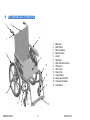
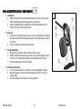
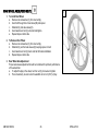
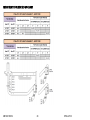
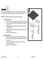
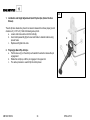
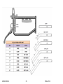
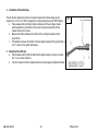
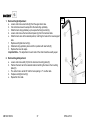
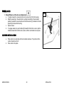
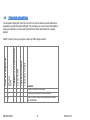
OWNERS MANUAL
1
CONTACT INFORMATION
FUTURE MOBILITY HEALTHCARE INC.
APPRECIATES YOUR FEEDBACK
Supplier: Please give this manual to the user of the wheelchair.
User: Please read this entire manual before using this wheelchair.
Thank you for choosing Future Mobility Healthcare Inc.
If you have any questions please do not hesitate to write or call us
at the address and telephone number below:
Future Mobility Healthcare Inc.
Customer Service Canada
3223 Orlando Dr.
Mississauga ON L4V 1C5
Phone: (888) 737-4011 or (905) 671-1661
Fax: (905) 671-3377
e-mail: [email protected]
www.futuremobility.ca
UM1340 REV02
2
STELLATO II
2
TABLE OF CONTENTS
TABLE OF CONTENTS
1
2
3
4
5
6
7
8
CONTACT INFORMATION .................................................. 2
TABLE OF CONTENTS........................................................ 3
PARTS OF THE WHEELCHAIR........................................... 5
NOTICE – READ BEFORE USE .......................................... 6
CHOOSE THE CORRECT CHAIR AND OPTIONS ....................6
REVIEW THIS MANUAL OFTEN ...............................................6
WARNING ..................................................................................6
LABEL LOCATIONS ............................................................ 7
GENERAL WARNINGS ........................................................ 8
USER WEIGHT LIMIT ................................................................ 8
WEIGHT TRAINING ...................................................................8
GETTING TO KNOW YOUR CHAIR...........................................8
TO REDUCE THE RISK .............................................................8
SAFETY CHECKLIST ................................................................ 9
CHANGES AND ADJUSTMENTS ..............................................9
GROUND TERRAIN ...................................................................9
CENTER OF GRAVITY ............................................................ 10
WHEELIES............................................................................... 10
ROLLING BACKWARDS.......................................................... 10
REACHING OR LEANING........................................................ 11
RAMPS AND SLOPES ............................................................. 11
TRANSFERS ........................................................................... 12
ATTENDANT WARNINGS ..................................................13
DESCENDING A CURB ........................................................... 13
CLIMBING A CURB .................................................................. 13
DESCENDING STAIRS............................................................ 13
COMPONENT WARNINGS .................................................15
UM1340 REV02
3
ANTI-TIP WHEELS .................................................................. 15
ARMRESTS ............................................................................. 15
BACK CANES .......................................................................... 15
FASTENERS............................................................................ 15
FOOTRESTS ........................................................................... 15
POSITIONING BELTS ............................................................. 16
QUICK-RELEASE AXLES ........................................................ 16
REAR WHEEL AXLES ............................................................. 16
REAR WHEEL LOCKS ............................................................. 17
9
WHEELCHAIR SET-UP AND ADJUSTMENTS ..................18
HEIGHT ADJUSTABLE FLIP-BACK ARM ................................ 18
CENTER PIVOT SWINGAWAY FOOTREST ........................... 19
DUAL SWINGAWAY FOOTREST ............................................ 20
DUAL PUSH SWINGAWAY FOOTREST ................................. 21
DUAL ELEVATING LEGREST AND HANGER ......................... 22
CASTER AND FORK ASSEMBLY ........................................... 23
REAR WHEEL AXLE (QUICK RELEASE) ................................ 25
REAR WHEEL AXLE (FIXED BOLT) ........................................ 26
REAR WHEEL AXLE POSITION PLACEMENT ....................... 27
FRONT SEAT TO FLOOR SET-UP CHART ............................. 28
REAR WHEEL MOUNT POSITION .......................................... 31
FOLDING AND UNFOLDING THR WHEELCHAIR .................. 32
SEAT SLING ............................................................................ 33
REAR ANTI-TIPS ..................................................................... 34
BACKREST .............................................................................. 37
BACK UPHOLSTERY .............................................................. 38
WHEEL LOCKS ....................................................................... 39
CUSHION INSTALLATION ...................................................... 39
TIE-DOWNS............................................................................. 40
10 TROUBLE SHOOTING ........................................................41
11 MAINTENANCE ...................................................................42
SAFETY INSPECTION CHECKLIST ........................................ 42
STELLATO II
GENERAL MAINTENANCE ..................................................... 44
SERVICE AND REPAIR ........................................................... 44
CLEANING YOUR CHAIR ........................................................ 44
12 WARRANTY ........................................................................46
LIFETIME ................................................................................. 46
FOR TWO (2) YEARS .............................................................. 46
FOR (90) DAYS ........................................................................ 46
LIMITATIONS ........................................................................... 46
WARRANTY PROCEDURES................................................... 46
UM1340 REV02
4
STELLATO II
3
PARTS OF THE WHEELCHAIR
4
3
7
1
1.
2.
3.
4.
5.
6.
7.
8.
9.
10.
11.
12.
13.
14.
2
6
12
10
11
Back Post
Rear Wheel
Back Upholstery
Back Post Grip
Anti-tip
Seat Sling
Wrap Flip-back Armrest
Wheel Lock
Side Frame
Caster Fork
Caster Wheel
Swing Away Footrest
Composite Footplate
Cross Brace
5
8
UM1340 REV02
9
13
14
5
STELLATO II
4
NOTICE – READ BEFORE USE
CHOOSE THE CORRECT CHAIR AND OPTIONS
Future Mobility Healthcare Inc. provides a choice of many
wheelchair styles to meet the requirements of the wheelchair user.
However, the final selection of the wheelchair and its options rests
solely with you and your health care advisor. Choosing the best
chair will depend on such things as:
1.
2.
3.
The level of your disability, strength, balance and
coordination.
The places and terrain that you are likely to use your
chair.
The need for options for your safety and comfort (such as
anti-tip tubes, positioning belts, or special seating
systems).
REVIEW THIS MANUAL OFTEN
Before using this chair you, and each person who may assist you,
should read this entire manual and make sure to follow all
instructions. Review the warnings often.
WARNING
The term “WARNING” are hazards or unsafe practices that may
cause severe injury or death to you or to other persons.
UM1340 REV02
6
STELLATO II
5
LABEL LOCATIONS
UM1340 REV02
7
STELLATO II
6
GENERAL WARNINGS
USER WEIGHT LIMIT
WARNING
NEVER exceed the weight limit of 275 pounds for a combined weight of rider and items carried. If you do exceed the limit, damage to your
chair, tip-over or loss of control may occur and cause severe injury to the rider or others.
WEIGHT TRAINING
WARNING
NEVER use this chair for weight training if total weight (rider plus equipment) exceeds 275 pounds. If you do exceed the limit, damage to your
chair, tip-over or loss of control may occur and cause severe injury to the rider or others.
GETTING TO KNOW YOUR CHAIR
WARNING
Every wheelchair is different. Take the time to learn the feel of this chair before you begin riding. Start slowly, with easy, smooth strokes. If you
are used to a different chair, you may use too much force and tip over. If you use too much force, damage to your chair, a fall, tip over or loss
of control may occur and cause severe injury to the rider or others.
TO REDUCE THE RISK
WARNING
1.
2.
3.
4.
BEFORE riding, you should be trained in the safe use of this chair by your health care advisor.
Practice bending, reaching and transfers until you know the limit of your ability. Have someone help you until you know what can
cause a fall or tip-over and how to avoid doing so.
Be aware that you must develop your own methods for safe use best suited to your level of function and ability.
NEVER try a new maneuver on your own until you are sure you can do it safely.
UM1340 REV02
8
STELLATO II
5.
6.
Get to know the areas where you plan to use your chair. Look for hazards and learn how to avoid them.
Use anti-tip tubes unless you are a skilled rider of this chair and are sure you are not at risk to tip over.
SAFETY CHECKLIST
WARNING
Before each use of your chair:
1. Make sure the chair rolls easily and that all parts work smoothly. Check for noise, vibration, or a change in ease of use. (They may
indicate low tire pressure, loose fasteners, or damage to your chair).
2. Repair any problem. Your authorized supplier can help you find and correct the problem.
3. Check to see that both quick-release rear axles are locked. When locked, the axle button will “pop out” fully.
CHANGES AND ADJUSTMENTS
WARNING
1.
2.
3.
4.
A.
If you modify or adjust this chair, it may increase the risk of a tip-over UNLESS you make other changes as well.
Consult your authorized supplier BEFORE you modify or adjust your chair, or contact Future Mobility Healthcare.
We recommend that you use anti-tip tubes until you adapt to the change, and are sure you are not at risk to tip over.
Unauthorized modifications or use of parts not supplied or approved by Future Mobility Healthcare may change the chair structure.
This will void the warranty and may cause a safety hazard.
GROUND TERRAIN
WARNING
1.
2.
Your chair is designed for use on firm, even surfaces such as concrete, asphalt and indoor floors and carpeting.
Do not operate your chair in sand, loose soil or over rough terrain. This may damage wheels or axles, or loosen fasteners of your
chair.
UM1340 REV02
9
STELLATO II
CENTER OF GRAVITY
WARNING
The point where this chair will tip forward, back, or to the side depends on its center of gravity and stability.
How your chair is set up, the options you select and the changes you make may affect the risk of a fall or tip-over.
1. The Most Important Adjustments Are:
a. The position of the rear wheels. The more you move the rear wheels forward, the more likely your chair will tip over backward.
b. The position of the carriage.
2. The Center Of Gravity Is Also Affected By:
a. A change in the set-up of your chair, including:
i. The seat height and seat angle.
ii. Backrest angle.
b. A change in your body position, posture or weight distribution.
c. Riding your chair on a ramp or slope.
d. The use of a back pack or other options, and the amount of added weight.
WHEELIES
WARNING
Because of the ability to adjust the center of gravity and changes in center of gravity that will result from operating the tilt in space feature of
this chair, as a user, do not perform wheelies in this wheelchair.
Doing a “wheelie” means: balancing on the rear wheels of your chair, while the front casters are in the air. It is dangerous to do a "wheelie" as
a fall or tip-over may occur.
ROLLING BACKWARDS
WARNING
Use extra care when you move your chair backward.
Your chair is most stable when you propel yourself forward.
You may lose control or tip over if one of the rear wheels hits an object and stops rolling.
1. Propel your chair slowly and smoothly.
UM1340 REV02
10
STELLATO II
2.
3.
If your chair has anti-tip tubes, make sure to lock them in place.
Stop often and check to be sure your path is clear.
REACHING OR LEANING
WARNING
If you reach or lean it will affect the center of balance of your chair. This may cause you to fall or tip over. When in doubt, ask for
help or use a device to extend your reach.
1. NEVER reach or lean if you must shift your weight sideways or rise up off the seat.
2. NEVER reach or lean if you must move forward in your seat to do so. Always keep your buttocks in contact with the backrest.
3. NEVER reach with both hands (you may not be able to catch yourself to prevent a fall if the chair tips).
4. NEVER reach or lean to the rear unless your chair has anti-tip tubes locked in place.
5. DO NOT reach or lean over the top of the seat back. This may damage one or both backrest tubes and cause you to fall.
6. If You Must Reach Or Lean:
a. Do not lock the rear wheels. This creates a tip point and makes a fall or tip-over more likely.
b. Do not put pressure on the footrests.
c. Move your chair as close as you can to the object you wish to reach.
RAMPS AND SLOPES
WARNING
Riding on a slope, which includes a ramp or side hill, will change the center of balance of your chair. Your chair is less stable when it
is at an angle. Anti-tip tubes may not prevent a fall or tip-over.
1. Do not use your chair on a slope steeper than 10%.
2. Always go as straight up and as straight down as you can. (Do not “cut the corner” on a slope or ramp.)
3. Do not turn or change direction on a slope.
4. Always stay in the CENTER of the ramp. Make sure ramp is wide enough that you are not at risk that a wheel may fall over the edge.
5. Do not stop on a steep slope. If you stop, you may lose control of your chair.
6. NEVER use rear wheel locks to try to slow or stop your chair. This is likely to cause your chair to veer out of control.
7. Beware Of:
a. Wet or slippery surfaces.
UM1340 REV02
11
STELLATO II
b.
c.
A change in grade on a slope (or a lip, bump or depression).
A drop-off at the bottom of a slope. A drop-off of as small as 3/4 inch can stop a front caster and cause the chair to tip forward.
TRANSFERS
WARNING
It is dangerous to transfer on your own. It requires good balance and agility. Be aware that there is a point during every transfer
when the wheelchair seat is not below you. To Avoid A Fall:
1. Work with your health care advisor to learn safe methods.
a. Learn how to position your body and how to support yourself during a transfer.
b. Have someone help you until you know how to do a safe transfer on your own.
2. Lock the rear wheels before you transfer. This keeps the rear wheels from rolling.
3. Make sure to keep pneumatic tires properly inflated. Low tire pressure may allow the rear wheel locks to slip.
4. Move your chair as close as you can to the seat you are transferring to. If possible, use a transfer board.
5. Rotate the front casters until they are as far forward as possible.
6. If you can, remove or swing footrests out of the way.
a. Make sure your feet do not catch in the space between the footrests.
b. Avoid putting weight on the footrests as this may cause the chair to tip.
UM1340 REV02
12
STELLATO II
7
ATTENDANT WARNINGS
DESCENDING A CURB
WARNING
Follow these steps to help a rider descend a curb or single step going BACKWARD:
1. Stay at the rear of the chair.
2. Several feet before your reach the edge of the curb or step, turn the chair around and pull it backward.
3. While looking over your shoulder, carefully step back until you are off the curb or stair and standing on the lower level.
4. Pull the chair toward you until the rear wheels reach the edge of the curb or step. Then allow the rear wheels to slowly roll down onto
the lower level.
5. When the rear wheels are safely on the lower level, tilt the chair back to its balance point. This will lift the front casters off the curb or
step.
6. Keep the chair in balance and take small steps backward.
7. Turn the chair around and gently lower front casters to the ground
CLIMBING A CURB
WARNING
Follow these steps to help the rider climb a curb or single step going FORWARD:
1. Stay behind the chair.
2. Face the curb and tilt the chair up on the rear wheels so that the front casters clear the curb or step.
3. Move forward, placing the front casters on the upper level as soon as you are sure they are past the edge.
4. Continue forward until the rear wheels contact the face of the curb or step. Lift and roll the rear wheels to the upper level.
DESCENDING STAIRS
WARNING
1. Use at least two attendants to move a chair and rider down stairs.
2. Move the chair and rider FORWARD down the stairs.
UM1340 REV02
13
STELLATO II
3.
4.
5.
The person at the rear is in control. He or she tilts the chair to the balance point of the rear wheels and rolls it to the edge of the top
step.
A second attendant stands on the third step from the top and grasps the hanger receiver or front most part of the seat rail. He or she
lowers the chair one step at a time by letting the rear wheels roll over the stair edge.
The attendants move to the next stair down. Repeat for each stair, until you reach the landing.
UM1340 REV02
14
STELLATO II
8
Armrests will not bear the weight of this chair.
1. NEVER lift this chair by its armrests. They may come loose
or break.
2. Lift this chair only by non-detachable parts of the main
frame.
COMPONENT WARNINGS
ANTI-TIP WHEELS
BACK CANES
WARNING
Anti-tip wheels can help keep your chair from tipping over
backward in most normal conditions.
1. Future Mobility Healthcare Recommends Use Of Anti-Tip
Tubes:
a. UNLESS you are a skilled rider of this chair and are
sure you are not at risk to tip over.
b. Each time you modify or adjust your chair. The change
may make it easier to tip backward. Use anti-tip tubes
until you adapt to the change, and are sure you are not
at risk to tip over.
2. When locked in place (in the “down” position) anti-tip tubes
should be BETWEEN 1 1/2 and 2 inches off the ground.
a. If set too HIGH, they may not prevent a tip-over.
b. If set too LOW, they may “hang up” on obstacles you
can expect in normal use. If this occurs, you may fall or
your chair may tip over.
3. Keep Anti-Tip Tubes Locked In Place UNLESS:
a. You have an attendant, or
b. You have to climb or descend a curb, or overcome an
obstacle, and can safely do so without them. At these
times, make sure anti-tip tubes are up, out of the way.
FASTENERS
WARNING
Many of the screws, bolts and nuts on this chair are special
high-strength fasteners. Use of improper fasteners may cause
your chair to fail.
1. ONLY use fasteners provided by an authorized supplier (or
ones of the same type and strength, as indicated by the
markings on the heads).
2. Over- or under-tightened fasteners may fail or cause
damage to chair parts.
3. If bolts or screws become loose, tighten them as soon as
you can.
FOOTRESTS
ARMRESTS
WARNING
WARNING
UM1340 REV02
WARNING
Always keep fingers away from the locking mechanism located at
the bottom of the back canes when folding the back down or pulling
it back up.
15
Footrests will not bear the weight of this chair
STELLATO II
1.
2.
3.
At the lowest point, footrests should be AT LEAST 2
INCHES off the ground. If set too LOW, they may “hang up”
on obstacles you can expect to find in normal use. This
may cause the chair to stop suddenly and tip forward.
To Avoid A Trip Or Fall When You Transfer:
a. Make sure your feet do not “hang up” or get caught in
the space between the footrests.
b. Avoid putting weight on the footrests, as the chair may
tip forward.
NEVER lift this chair by the footrests. Footrests detach and
will not bear the weight of this chair. Lift this chair only by
non-detachable parts of the main frame.
6.
7.
Make sure the rider can easily remove the belts in an
emergency.
NEVER Use Positioning Belts:
a. As a patient restraint. A restraint requires a doctor’s
order.
b. On a rider who is comatose or agitated.
c. As a motor vehicle restraint. In an accident or sudden
stop the rider may be thrown from the chair.
Wheelchair seat belts will not prevent this, and further
injury may result from the belts or straps.
QUICK-RELEASE AXLES
POSITIONING BELTS
WARNING
1.
WARNING
Use positioning belts ONLY to help support the rider’s posture.
Improper use of these belts may cause severe injury to or death
of the rider.
1. Make sure the rider cannot slide down in the wheelchair
seat.
2. If this occurs, the rider may suffer chest compression or
suffocate due to pressure from the belts.
3. The belts must be snug, but must not be so tight that they
interfere with breathing. You should be able to slide your
open hand, flat, between the belt and the rider.
4. A pelvic wedge or a similar device can help keep the rider
from sliding down in the seat. Consult with the rider’s
doctor, nurse or therapist to find out if the rider needs such
a device.
5. Use positioning belts only with a rider who can cooperate.
UM1340 REV02
16
2.
Do not use this chair UNLESS you are sure that both quickrelease rear axles are locked. An unlocked axle may come
off during use and cause a fall.
An axle is not locked until the quick-release button pops out
fully. An unlocked axle may come off during use, resulting
in a fall, tip-over or loss of control and cause severe injury
to the rider or others.
REAR WHEEL AXLES
WARNING
A change in set-up of the rear wheels will affect the center of
balance of your chair.
1. The farther you move the rear axles FORWARD, the more
likely it is that your chair will tip over backward.
STELLATO II
2.
3.
Consult your doctor, nurse or therapist to find the best rear
axle set-up for your chair. Do not change the set-up
UNLESS you are sure you are not at risk to tip over.
Adjust the rear wheel locks after you make any change to
the rear axles.
a. If you fail to do so, the locks may not work.
b. Make sure wheel locks are embedded in tires at least
1/8 inch when locked.
REAR WHEEL LOCKS
WARNING
Rear wheel locks are NOT designed to slow or stop a moving
wheelchair. Use them only to keep the rear wheels from rolling
when your chair is at a complete stop.
1. NEVER use rear wheel locks to try to slow or stop your
chair when it is moving. Doing so may cause you to veer
out of control.
2. To keep the rear wheels from rolling, always set both rear
wheel locks when you transfer to or from your chair.
3. Low pressure in a rear tire may cause the wheel lock on
that side to slip and may allow the wheel to turn when you
do not expect it.
4. Make sure wheel locks are embed in tires at least 1/8 inch
when locked. If you fail to do so, the locks may not work.
UM1340 REV02
17
STELLATO II
9
WHEELCHAIR SET-UP AND ADJUSTMENTS
1
HEIGHT ADJUSTABLE FLIP-BACK ARM
1.
Engaging and Disengaging Flip-back Arm
a. To disengage, press and hold the release lever (C) while pulling up on the
arm body (A).
b. Flip the armrest back; it remains attached to the rear pivot mount (E).
c. To reattach move the armrest down into place.
d. Press down until the release lever (C) locks into the receiver (D).
2.
Height Adjustment
a. Turn the release knob (B) counter clock-wise to disengage the ball pin.
b. Slide top armrest pad up or down to desired height and ‘click’ into position.
c. Turn the release knob (B) clock-wise to lock the armpost.
d. Push arm pad to check that it is locked firmly into place.
UM1340 REV02
18
STELLATO II
CENTER PIVOT SWINGAWAY FOOTREST
2
1.
Installation
a. Position the center pivot of the swingaway footrest (C) onto the side frame
vertical tube (B) with the swingaway footrest facing out from the wheelchair.
b. Swing the footrest inwards such that the swingaway latch (A) ‘clicks’ into
place onto the U-bolt.
2.
Removal
a. To remove the footrest, pull outward onto the handle latch (A) releasing the
mechanism from the U-bolt and swing the footrest outwards.
b. Pull up on the footrest to remove from wheelchair.
3.
Height Adjustment
a. Remove bolt (D) which holds the extension tube in place.
b. Slide the footrest extension tube up or down to the desired height. Note a
minimum of 2” should be kept between the footplate (E) and the floor.
c. Re-install and tighten the bolt (D) in place.
UM1340 REV02
19
STELLATO II
DUAL SWINGAWAY FOOTREST
1.
Installation
a. Position the center pivot of the swingaway footrest (C) onto the side frame
vertical tube (B) with the swingaway footrest facing out from the wheelchair.
b. Swing the footrest inwards such that the swingaway latch (A) ‘clicks’ into
place onto the hanger block.
2.
Removal
a. To remove the footrest, pull up onto the handle latch (A) releasing the
mechanism from the hanger and swing the footrest outwards or inwards.
b. Pull up on the footrest to remove from wheelchair.
3.
Height Adjustment
a. Remove bolt (D) which holds the extension tube in place.
b. Slide the footrest extension tube up or down to the desired height. Note a
minimum of 2” should be kept between the footplate (E) and the floor.
c. Re-install and tighten the bolt (D) in place.
UM1340 REV02
20
3
STELLATO II
DUAL PUSH SWINGAWAY FOOTREST
4
1.
Installation
a. Position the center pivot of the swingaway footrest (C) onto the side frame
vertical tube (B) with the swingaway footrest facing out from the wheelchair.
b. Swing the footrest inwards such that the swingaway pin (A) ‘clicks’ into
place onto the hanger block.
2.
Removal
a. To remove the footrest, push onto the handle latch (F) releasing the
mechanism from the hanger and swing the footrest outwards or inwards.
b. Pull up on the footrest to remove from wheelchair.
3.
Height Adjustment
a. Remove bolt (D) which holds the extension tube in place.
b. Slide the footrest extension tube up or down to the desired height. Note a
minimum of 2” should be kept between the footplate (E) and the floor.
c. Re-install and tighten the bolt (D) in place.
UM1340 REV02
21
STELLATO II
DUAL ELEVATING LEGREST AND HANGER
1.
Installation
a. Position the center pivot of the elevating legrest (C) onto the hanger (B)
with the elevating footrest facing out from the wheelchair.
b. Swing the elevating legrest inwards such that the swingaway latch (A)
‘clicks’ into place onto the hanger block.
2.
Removal
a. To remove the elevating legrest, pull up onto the handle latch (A) releasing
the mechanism from the hanger and swing the elevating legrest outwards
or inwards.
b. Pull up on legrest to remove from wheelchair.
3.
Height Adjustment
a. Remove bolt (D) which holds the extension tube in place.
b. Slide the footrest extension tube up or down to the desired height. Note a
minimum of 2” should be kept between the footplate (E) and the floor.
c. Re-install and tighten the bolt (D) in place.
4.
Elevation Adjustment
a. Turn the release knob (F) counter-clock wise to disengage the ball pin.
b. Move the legrest up or down to desired height. Listen for the “clicks” to
verify position.
c. Turn the release knob clock wise to lock the position.
UM1340 REV02
22
5
STELLATO II
CASTER AND FORK ASSEMBLY
6
1.
Installation of New Caster and Fork
a. Remove dust cover (A) from caster housing (D). Gently pry off cover using
a back and forth motion with screw driver.
b. Caster assembly holds one nut (B) and one washer (immediately below the
nut). Remove nut and washer.
c. Remove caster fork and stem assembly (E) (F).
d. Insert caster stem and fork (E) (F) into caster housing (D) and place washer
on stem.
e. Replace nut (B) on caster stem and tighten until all play is removed; then
loosen approximately 1/8 turn, allowing for free rotation.
f. Replace dust cover to caster housing.
2.
Caster Height Adjustment
a. Loosen and remove axle bolt from caster (I).
b. Set axle at desired height using pre-set holes in the fork.
c. Replace and tighten bolt.
d. Repeat on other side.
UM1340 REV02
23
STELLATO II
3. Caster Fork Angle Adjustment (Rear Facing Position Shown)
For optimum performance, the caster housing should always be at a 90º angle to
the floor (perpendicular to the ground). This adjustment is made with an eccentric
(offset) attachment bolt mechanism.
a.
b.
c.
d.
4.
Loosen bolts (G) from caster housing (D).
Rotate notched cam plate (H) such that the fork (F) is set to 0°, 3° or 6°.
The angle will depend on the seat drop, which is either 0, 1” or 2”.
When the position of the cam plate (H) is set retighten the two retaining
bolts (G), fixing the fork in place.
Repeat for the other side.
Caster Housing Reversibility
The caster housing is generally mounted in a rear-facing position. If required, the
caster housing can be reversed and mounted in the forward-facing position.
a.
b.
To reverse the caster housing, the left housing should be mounted on the
right side of the frame.
The right housing should be mounted on the left side of the frame.
UM1340 REV02
24
STELLATO II
REAR WHEEL AXLE (QUICK RELEASE)
7
1.
Quick Release Axle Check
Do not use this chair UNLESS you are sure both quick-release axles are locked.
An unlocked axle may come off during use and cause a fall.
Note – Axle is not locked until the quick-release button (A) pops out fully.
2.
To Install Rear Wheel
a. Depress quick-release button (A) fully. This will release tension on ball
bearings at other end.
b. Insert axle through hub of rear wheel (B).
c. Keep pressure on button (A) as you slide axle (C) into axle sleeve (D).
d. Release button to lock axle in sleeve. Adjust axle if it does not lock.
e. Repeat steps on other side.
3.
To Remove Rear Wheel
a. Depress quick-release button (A) fully.
b. Remove wheel by sliding axle (C) out of axle sleeve (D).
c. Repeat steps on other side.
4.
Rear Wheel Axle Adjustment
Proper axle sleeves adjustment should be maintained for optimum performance
of the wheelchair.
a. To adjust the axle you will need a 5/8" wrench to turn the outside axle nut.
b. You will also need a 10mm wrench on the opposite end of the axle, and
prevent the axle from turning.
c. Turn the outside axle nut clockwise to tighten.
d. There should only be zero to ten thousandths of an inch (.010") of play.
UM1340 REV02
25
STELLATO II
REAR WHEEL AXLE (FIXED BOLT)
8
1.
To Install Rear Wheel
a. Remove nut and washer (C) from hex bolt (A).
b. Insert bolt through hub of rear wheel (B) and spacer.
c. Slide bolt (A) into axle sleeve (D).
d. Insert washer and nut (C) onto bolt and tighten.
e. Repeat steps on other side.
2.
To Remove Rear Wheel
a. Remove nut and washer (C) from hex bolt (A).
b. Slide bolt (A) out from axle sleeve (D) keeping spacer on bolt.
c. Insert washer and nut (C) back onto bolt for future installation.
d. Repeat steps on other side.
3.
Rear Wheel Axle Adjustment
Proper axle sleeves adjustment should be maintained for optimum performance
of the wheelchair.
a. To adjust the play in the wheel, turn the nut (C) clock-wise to tighten.
b. There should only be zero to ten thousandths of an inch (.010") of play.
UM1340 REV02
26
STELLATO II
REAR WHEEL AXLE POSITION PLACEMENT
1.
To Re-position Rear Wheel
a. Remove rear wheel from axle plate sleeve (A) (See Removing Rear Wheel
in previous section).
b. Remove insert plug (B) from desired new mounting location by prying with
fingernail or pushing from rear with allen key.
c. Plug in insert into previous hole where rear wheel was removed from
sleeve.
d. Insert rear wheel into new position (See Installing Rear Wheel in previous
section).
e. Repeat steps on other side.
Important Note – The adjustment on each side of the chair should be exactly
equal.
Important Note – The adjustment should be done by an authorized dealer only.
UM1340 REV02
27
STELLATO II
FRONT SEAT TO FLOOR SET-UP CHART
UM1340 REV02
28
STELLATO II
UM1340 REV02
29
STELLATO II
UM1340 REV02
30
STELLATO II
9
REAR WHEEL MOUNT POSITION
1.
Rear Wheel Active to Stable Position Change
a. Loosen and remove lock-nuts from bolts (A).
b. DO NOT remove bolt (C) from mounting plate (B). The mounting plate
assembly and all insert bushing are to remain intact during the change of
position.
c. After the mounting plate is repositioned replace and tighten all lock-nuts
onto bolts (A).
Important Note – The adjustment on each side of the chair should be exactly
equal.
Important Note – The adjustment should be done by an authorized dealer only.
Note – Use a torque setting of 75 in-lbs. when tightening the lock-nuts.
2. Weight Distribution
Weight distribution between the front and rear wheels is primarily adjusted by moving
the rear axles forward or rearward on the frame.
ACTIVE
9
Moving the axles REARWARD provides better forward and rearward tipping stability.
Moving the axles FORWARD shifts more of the rider’s weight onto the rear wheels,
providing the following benefits: the front end of the wheelchair becomes lighter, thus
reducing the turning effort, and with a shorter wheelbase the turning radius is
reduced.
STABLE
UM1340 REV02
31
STELLATO II
FOLDING AND UNFOLDING THR WHEELCHAIR
1.
Folding the Wheelchair
a. Remove the front swingaway footrests. Refer to swingaway footrest
removal on the previous pages.
b. With both hands, grasp the middle pull strap of the seat upholstery (A) and
lift up until the seat rail disengages from the saddles (B).
c. Place excess seat upholstery over the armrest when in the folded position.
2.
Unfolding the Wheelchair
a. Press down on the seat rail and the seat upholstery with the entire hand.
DO NOT place any part of the hand under the seat rail.
b. Both seat rails must lock into the seat rail saddles (B) on both side frames.
c. Replace the front swingaway footrests if required.
UM1340 REV02
32
10
STELLATO II
SEAT SLING
11
The seat sling can be adjusted through the use of hook and loop material beneath the
seat. Seat sling also includes a folding strap on the seat to assist in folding the chair.
NOTE– The seat sling folding strap is NOT intended as a carrying strap.
1.
Seat Sling Adjustments
a. Remove screws (B) and seat rail end caps (A) at the front of the chair.
b. Slide the seat sling (C) with plastic retaining rods from the channels in
the seat rails.
c. Readjust hook and loop material underneath the seat sling to obtain
the desired tension.
d. Reinsert the seat sling (C) and plastic retaining rods into the channels
in the seat rails.
e. Replace the end caps and screws.
2.
Replacing Seat Sling
a. Remove screws (B) and seat rail end caps (A) at the front of the chair.
b. Slide the seat sling (C) with plastic retaining rods from the channels in
the seat rails.
c. Reinsert the new seat sling (C) and plastic retaining rods into the
channels in the seat rails.
d. Replace the end caps and screws.
UM1340 REV02
33
STELLATO II
REAR ANTI-TIPS
12A
1.
Installation and Height Adjustment Quick Flip Ant-tips (Active Position
Shown)
The anti-tip tube wheels may have to be raised or lowered to achieve proper ground
clearance of (1-1/2" to 2"). Refer to following set-up chart.
a. Loosen and remove lock-nuts from bolts (A).
b. Insert anti-tip assembly (B) onto rear side frame in desired location using
pre-set holes.
c. Replace and tighten lock-nuts.
2.
Flipping Up Quick Flip Anti-tips
a. Pull the sleeve (C) on the anti-tip out towards the wheel to release the pin
engagement
b. Rotate the anti-tip up until the pin engages in the upper slot.
c. The same procedure is used to flip the anti-tip down.
UM1340 REV02
34
STELLATO II
UM1340 REV02
35
STELLATO II
3.
Installation of Fixed Anti-tips
The anti-tip tube wheels may have to be raised or lowered to achieve proper ground
clearance of (1-1/2" to 2"). Refer to diagram for corresponding tube size to RSTF heights.
a. Press release button (A) IN and insert anti-tippers with the anti-tipper wheels
pointing toward the ground/ floor into the rear mounting bracket (B) until the
release button locks in place.
b. Measure the distance between the bottom of the anti-tipper wheels and the
ground/ floor.
c. If the distance between the bottom of the anti-tipper wheels and the ground/ floor is
not 1 ½ and 2-inches, adjust anti-tippers.
4.
12B
Adjusting Fixed Anti-tips
a. Press release button (C) IN and slide the anti-tipper wheel up or down to achieve
the 1 ½ to 2-inches clearance.
b. Check to make sure that the release buttons are fully engaged in adjustment holes.
UM1340 REV02
36
STELLATO II
BACKREST
1.
Backrest Height Adjustment
a. Loosen and remove rear bolts (E) from the upper back cane.
b. Cut and remove lower tie wraps from the back sling upholstery.
c. Slide the back sling upholstery up to expose the fixing hex bolt (A).
d. Loosen and remove the hex bolt and spacer (A) from the backrest tube.
e. Slide the back cane to the desired position, matching the holes in the lower support
tube.
f. Replace and tighten hex bolt (A).
g. Slide back sling upholstery down and fix in position with rear bolts (E)
h. Replace the lower tie wraps.
Important Note – The adjustment on each side of the chair should be exactly equal.
2.
Backrest Angle Adjustment
a. Loosen and remove bolt (C) from the back rest mounting plate (D).
b. Position the back rest in the desired location matching the holes in the mounting
plate (D).
c. The center hole is set at 90° and the hole spacing is 7° on either side.
d. Replace and tighten bolt (C).
e. Repeat for other side.
UM1340 REV02
37
13
STELLATO II
BACK UPHOLSTERY
1.
Replacing Back Sling
a. Loosen and remove rear bolts (A) from the mounting plate.
b. Cut and remove lower tie wraps from the back sling upholstery.
c. Loosen and remove upper upholstery bolts (B) from the back cane.
d. Remove the back canes with back upholstery from the chair.
e. Slide off the backrest upholstery (C) from the back canes.
f. Slide on the new backrest upholstery and fix in place with upper upholstery
bolts (B).
g. Replace the backrest to the mounting plates matching the holes in the lower
support tube.
h. Replace and tighten bolts (A).
i. Replace the lower tie wraps.
Important Note – The adjustment on each side of the chair should be exactly equal.
UM1340 REV02
38
14
STELLATO II
WHEEL LOCKS
1.
Manual Wheel Lock Function and Adjustment
a. To adjust, loosen the screws (A) but do not remove them from the housing.
b. Slide the assembly in the wheel lock mounting bracket (B) (in the activated
position) towards the rear wheel tire until the brake shoe (C) embeds into the tire
preventing the wheel from turning.
c. Tighten screws.
d. To engage wheel lock, push handle (D) forward for the Push to Lock or pull the
handle rearward for the Pull to lock version until the mechanism locks in place.
15
CUSHION INSTALLATION
a.
b.
Place cushion on seat sling with hook material side down. The pommel of the
cushion should be in front.
Press cushion into place.
UM1340 REV02
39
STELLATO II
TIE-DOWNS
1.
16
Front and Rear Tie-Downs
a. If possible and feasible, the rider should transfer to the Original Equipment
Manufacturer vehicle seat and use the vehicle restraint.
b. If the wheelchair is used for transport, it must be used in a forward-facing seating
position.
c. The rider must not weigh more than 275 lbs.
d. Front attachment point (B) and rear attachment point (A)
UM1340 REV02
40
STELLATO II
10
TROUBLE SHOOTING
You will need to adjust your chair from time to time in order to achieve the best performance
(especially if you alter the original settings). This chart gives you a quick look at what might be
causing your problem. You may need to look farther to find the best solution for a specific
problem.
X
X
X
X
UM1340 REV02
Looseness in Chair
X
X
Squeaks and Rattles
X
Caster Flutter
Sluggish Turn or Performance
Wheels
Drift
Chair Veers Right/Left
NOTE– To keep track of your progress, make only ONE change at a time.
X
X
Solutions
Check for loose nuts and bolts
Check angle adjustable caster assembly
Check that rear wheels are equally spaced away
from seat frame.
41
STELLATO II
11
MAINTENANCE
SAFETY INSPECTION CHECKLIST
TIRES
Inspect for flat spots, cracks and wear Caution: as with any vehicle, the wheels and tires should be
checked periodically for cracks and wear and should be replaced.
UM1340 REV02
42
X
Monthly
X
X
X
X
X
X
X
X
X
X
X
X
X
X
X
X
X
Periodically
Item
GENERAL
Wheelchair rolls straight (no excessive drag or pull to one side)
FRAME AND CROSSING TUBES
Inspect for loose or missing hardware
Inspect for bent frame or cross-tubes
WHEEL LOCKS
Do not interfere with tires when rolling
Pivot points free of wear and looseness
Wheel locks easy to engage
Wheel locks prevent chair from moving when engaged
SEAT AND BACK
Inspect for rips or sagging
Inspect for loose or broken hardware
Inspect cane and hand grips for wear/looseness
Weekly
Initially
Initial adjustments should be made to suit your body structure needs and preference. Please follow these maintenance procedures.
X
X
X
X
STELLATO II
X
REAR WHEELS
If equipped, quick-release axles lock properly
No excessive side movement or binding when lifted and spun
Inspect for cracked, bent or broken spokes
HANDRIMS
Inspect for signs of rough edges or peeling
FRONT CASTERS/FORKS
Inspect caster fork assembly for proper tension by spinning caster; caster should come to a gradual stop
Adjust bearing system if wheel wobbles or binds to a stop. Ensure wheel bearings are clean and free of
moisture.
Check stem caster journal and lock nut for tightness
Inspect casters for cracks and wear
Inspect for cracked, bent or broken spokes
CLEANING
Clean upholstery and armrests
UM1340 REV02
43
X
X
X
X
X
X
X
X
X
X
X
X
X
X
X
X
X
X
X
X
STELLATO II
X
GENERAL MAINTENANCE
1.
2.
3.
4.
5.
6.
5.
Maintaining your chair in good working order will keep it
functioning properly and help extend the working life of the
chair.
Clean your chair often.
Make sure to replace worn or damaged parts as soon as
possible to prevent future injury.
It is recommended to have any work done on the chair by
an authorized dealer.
Follow the safety inspection checklist chart for optimum
performance.
We recommend that once a year to have a complete
inspection, service and safety check of your chair by an
authorized dealer.
6.
CLEANING YOUR CHAIR
1.
WARNING
Failing to follow these recommendations could lead to possible
injury.
SERVICE AND REPAIR
1.
2.
3.
4.
Please contact the dealership or supplier from where the
wheelchair was purchased for service and moderate repair.
In some circumstances, it may be necessary to return your
wheelchair to Future Mobility for repairs.
Contact Future Mobility directly by telephone, fax, or e-mail
to obtain information regarding repair at Future Mobility
facilities.
You will be asked by the Customer Service Representative
for the serial number that is affixed to the wheelchair.
UM1340 REV02
44
If any of the following conditions are observed, the
wheelchair must be serviced at Future Mobility:
e. Any part of the frame is cracked or broken
f. Any weld is cracked or broken
For safe and secure shipping, the wheelchair must be
placed in a suitable carton, or fastened to a pallet, to
ensure it does not sustain damage during shipping. Contact
Future Mobility to receive specific instructions for
packaging and shipping your wheelchair. Alternatively,
Future Mobility may arrange for pick-up.
5.
6.
Cleaning your Seat and Back
a. Remove the outer and inner cover if required and
hand wash with a small amount of detergent.
b. Hang to dry the covers, do not machine dry or
wring out.
c. Use multipurpose disinfectant to spray seat, scrub
with soft brush if needed.
d. Test an inconspicuous area first for color-fastness.
e. DO NOT USE HOT AIR FOR DRYING.
f. DO NOT IMMERSE the cushion or back foam in
water or cleaning solution.
g. Some color leeching from the cover onto the foam
is normal and cannot be washed out.
Paint Finish
a. Clean the painted surfaces with mild soap at least
once a month
b. Protect the paint with a coat of non-abrasive auto
wax every three months.
Axles and Pivot Joints
STELLATO II
a.
b.
Clean around axles and moving parts WEEKLY
with a slightly damp (not wet) cloth.
Wipe off or blow away any dust or dirt on axles or
moving parts.
WARNING
Do not use abrasive powders or scouring pads on painted
surfaces.
Do not ever submerge chair in water.
Do not use cleaning products without consulting the products’
instructions and taking appropriate precautions for human
exposure to chemicals.
UM1340 REV02
45
STELLATO II
12
WARRANTY
LIFETIME
Wheelchair Frame and Cross- Brace
1. Future Mobility Healthcare Inc. guarantees the frame and
cross brace against defects in material and workmanship
for life or for as long as the original purchaser owns the
chair.
2. This warranty is void if:
a. The chair is shown to be abused.
b. The chair is not maintained as recommended in
the owner’s manual.
c. The chair is transferred to a different person from
the original owner.
FOR (90) DAYS
Cushion and Back Upholstery
1. Future Mobility Healthcare Inc. guarantees the wheelchair
cushion and back upholstery to be free of defects in
material and workmanship for 90 days.
LIMITATIONS
1.
FOR TWO (2) YEARS
Wheelchair Back and Cushions (Excluding Upholstery)
1. Future Mobility Healthcare Inc. guarantees the back and
cushion (Excluding Upholstery) to be free of defects in
material and workmanship for two years.
Wheelchair Components Excluding Limitations
1. Future Mobility Healthcare Inc. guarantees the wheelchair
components to be free of defects in material and
workmanship for two years.
2.
3.
We do not warrant:
a. Tires, Tubes, Caster Wheels, Push-Handles and
Grips.
b. Damage from negligence, accident, misuse, or
from improper installation or repair.
c. Products modified without written consent from
FMHI.
d. Damage from exceeding the wheelchair weight
limit.
This warranty is VOID if the original chair serial number
label is removed or altered.
This warranty is not transferable and only applies to the
first consumer purchase of this wheelchair through an
authorized Future Mobility Dealer.
WARRANTY PROCEDURES
1.
UM1340 REV02
46
If within this warranty period the product shall be proven to
be defective, such product shall be repaired or replaced, at
FMHI discretion.
STELLATO II
2.
3.
4.
5.
FMHI’s sole obligation and your exclusive remedy under
this warranty shall be limited to the repair and/or
replacement of the product or its parts.
This warranty does not include any labor or shipping
charges incurred in replacement part installation or repair
of any product.
For warranty service, please contact the dealer from whom
you purchased your FMHI product. In the event you do not
receive satisfactory warranty service, please write directly
to FMHI.
DO NOT return products to FMHI without our prior consent.
The defective unit or parts must be returned for warranty
inspection within thirty (30) days of the return authorization
date. (FMHI will issue a return authorization number).
Please prepay all shipping charges; C.O.D. shipments will
be refused.
The foregoing warranty is exclusive and in lieu of all other expressed
warranties. It shall not extend beyond the duration of the expressed
warranty provided herein and the remedy for violations of any
implied warranty shall be limited to repair or replacement of the
defective product pursuant to the terms contained herein. FMHI shall
not be liable for any consequential or incidental damages
whatsoever.
UM1340 REV02
47
STELLATO II
UM1340 REV02
48
STELLATO II
UM1340 REV02
49
STELLATO II
UM1340 REV02
50
STELLATO II
UM1340 REV02
51
STELLATO II
UM1340 REV02
52
STELLATO II