Transcript
IP314 USER GUIDE
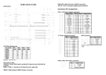
Dimensions:
Connector Pin Assignment :
J2: ATX Power Supply Connector
11
1
20
10
Signal Name
3.3V
-12V
Ground
PS-ON
Ground
Ground
Ground
-5V
+5V
+5V
Pin #
11
12
13
14
15
16
17
18
19
20
J4 :Power Supply Connector
Pin #
1
2
3
4
5
6
Pin #
1
2
3
4
5
6
7
8
9
10
J7~J8: USB Connectors
Signal
Name
Vcc
D0D0+
Ground
Signal Name
+5V
-5V
-12V
+12V
+3.3V
GND
8 PCI slots : S-PCI1 ~ S_PCI8 Remarks : 32 bits /5V by bridge.
2 ISA slots : ISA1~ISA2
PCI-Express slots:
PCIEX16: 16-lane PCI Express port(x16 PCI Express port) intended for graphics.
PCIEX4-1~ PCIEX4-2 : General x4 PCI Express port supported.
RESET1: SHB hardware RESET bottom connector.
PWR-BTN1: SHB ATX power ON/OFF connector.
Pin
Pin
1
2
3
4
5
6
7
8
Signal
Name
Ground
D1+
D1Vcc
Remark: USB are derived from SHB.
FAN1, FAN2: Fan Power Connectors
Pin #
1
2
3
Signal Name
3.3V
3.3V
Ground
+5V
Ground
+5V
Ground
Power good
5VSB
+12V
Signal Name
Ground
+12V
Rotation detection