1
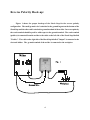
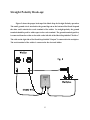
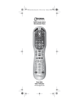
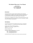
Shock Stop
User’s Guide
TM
Model No.: A720-ED-uSS-010602
For use on Low Voltage Welders
Caution: Read and follow all Safety
Rules and Operating Instructions for this
device.
Manufactured by DDC Technology
ED-MAN-29-11-02
Table of Contents
Page
Introduction......................................................................................................................
2
What Shock StopTM Does..................................................................................................
2
Installation Instructions...................................................................................................
3
Operation..........................................................................................................................
6
Caution..............................................................................................................................
7
Fault Detection.................................................................................................................
7
Error Codes....................................................................................................................... 8
Frequently Asked Questions...........................................................................................
9
Warranty and Liability...................................................................................................
11
Shock StopTM is a trademark owned by DDC Technology. Throughout the manual where the Shock Stop
name appears it is understood to be Shock Stop TM.
Introduction
Shock Stop is a very unique welding shock protection device. Everyday welders face
serious hazards from electrical shock. Welding as an advancing trade is being done in the
workplace with an ever increasing frequency. Many times welders must work under adverse
conditions that are conducive to receiving electrical shocks.
Previous methods of protection included things like latex gloves, rubber mats,
anti-moisture sprays, and other non-conductive barriers. These methods have proven to be less
than adequate and time consuming for the majority of situations. However, these were all that
were available until now.
Shock Stop is an all electronic device that requires no intervention on the part of the
user. Shock Stop functions automatically between the user and the welder when properly
installed and operated.
What the Shock Stop Does
Shock Stop uses proprietary technology to reduce the risk of electrical shock that can
occur in the welding process. The vast majority of electrical shock occurs when the user is
changing the welding rod in the electrode holder. Other devices such as voltage reducers
either switch off part of the primary winding to reduce the output voltage of the welder, or
some voltage reducers shunt part of the output of the welder away from the user and reduce
the output voltage. In all these cases the user is still in contact with the welder output. When
properly installed and operating Shock Stop acts as a block of the entire welder output from
coming in contact with the user. As a result Shock Stop reduces the potential at the electrode
to an extremely low sense voltage. Current is regulated in the microamp range, greatly
reducing or eliminating any serious hazard. Shock Stop does not create heat or suffer from the
inherent heat-induced trip-out problems of shunt type units. Diagnostics built into the Shock
Stop allow it to test its own internal circuitry to detect any problems within the unit, allowing
the user to ensure that the unit is functioning properly.
2
Installation Instructions
Shock Stop installation is very simple. The electronics are enclosed in a CSA/UL
approved electrical enclosure fitted with rear mounting lugs. The unit can be mounted directly
on a backplate of suitable material with the enclosed mounting bolts. The user may also attach
the 4 enclosed lugs as desired and the Shock Stop can be mounted on a frame, or plate.
It is preferable that the Shock Stop be mounted in close proximity to the welder that the
Shock Stop will be used on. This facilitates hook-up of the small ground wire that is attached
to the welder from the Shock Stop. This is one of the unique features of the Shock Stop . It
can be mounted near the welder in a clean dry environment and the user will still be protected
out in the work environment. By mounting the Shock Stop in a more hospitable environment
the life of the Shock Stop will be prolonged.
After the enclosure is mounted, the electrical connections to the Shock Stop must be
made. The Shock Stop comes with a longer welding cable on the input (left) side, which is
labelled as "Welder". The cable on the left is longer to facilitate attachment to the welder
without having to use cable extensions. The user must attach whatever style of ends they
choose. The output (right) side, which is labelled as "Output" is the output of the Shock Stop.
The ground lug is located on the bottom of the Shock Stop. The enclosed ground wire is
attached from the grounding lug on the bottom of the Shock Stop to the welder.
The Shock Stop can be used in either reverse polarity or straight polarity. The hook-up
for each method is different. The following diagrams illustrate the proper hook-up of the
Shock Stop for the various configurations. The low voltage model Shock Stop is designed for
use on welders whose operating voltage is 25 to 50 Volts.
3
Reverse Polarity Hook-up:
Figure 1 shows the proper hook-up of the Shock Stop for the reverse polarity
configuration. The small ground wire is attached to the ground lug nut on the bottom of the
Shock Stop and the other end is attached to ground terminal of the welder. In reverse polarity
the work terminal should be positive with respect to the ground terminal. The work terminal
(positive) is connected from the welder to the cable on the left side of the Shock Stop labelled
"Positive". The cable on the right side of the Shock Stop labelled "Output" is connected to the
electrode holder. The ground terminal of the welder is connected to the workpiece.
4
Straight Polarity Hook-up:
Figure 2 shows the proper hook-up of the Shock Stop for Straight Polarity operation.
The small ground wire is attached to the ground lug nut on the bottom of the Shock Stop and
the other end is attached to work terminal of the welder. In straight polarity the ground
terminal should be positive with respect to the work terminal. The ground terminal (positive)
is connected from the welder to the cable on the left side of the Shock Stop labelled "Positive."
The cable on the right side of the Shock Stop, labelled "Output" is connected to the workpiece.
The work terminal of the welder is connected to the electrode holder.
5
Operation
Once the Shock Stop is properly connected the unit will power up when the welder is
turned on. Upon start up the power LED should come on first, followed by the Run LED after
a short delay. Once the run LED is lit the unit is ready to use. The user should then initiate
the diagnostics test by pushing the button on the front of the Shock Stop to ensure that unit is
functioning properly before using. Once the unit has returned to Run mode after the Test OK
indicates the unit is ready for use, the user merely has to strike the rod against the workpiece
in his normal motion and the striking of the arc is what initiates the Shock Stop to send power
to the electrode. Once activated, the user then has 3 seconds in which to establish the arc.
During this 3 second period the Enabled LED is lit indicating that power is being sent from the
Shock Stop. This timing has been set to work most efficiently with the way in which welders
practice their art. If the arc is established, the user can continue to weld. Upon cessation of
the arc the unit will automatically return to the de-energized safe state and the user will have
to strike the electrode to the workpiece to re-establish the arc. If the arc is not established
within the 3 second period the unit reverts automatically back to safe mode and the user must
re-strike to establish the arc. The Shock Stop is transparent to the user when welding and in
no way affects the weld.
The Shock Stop designed for the low voltage welders such as mobile welders can handle
the changes in voltage that occur as the welder changes from the low idle state to the high idle
state. However, the Shock Stop should never be subjected to the high idle voltage continuously.
Running high idle continuously could cause premature failure of some of the internal
components. The Shock Stop is designed to operate at a minimum low idle voltage of 25 volts.
If the welder does not shift properly from low idle to high idle disconnect the Shock Stop until
the welder is repaired.
During welding the user may notice that the LED's on the front panel dim considerably.
This is normal. The user may also notice that the "Fault" LED may happen to flash during
6
this low voltage situation. However, this is perfectly normal and the unit will return to full
functionality when the voltage level again rises. Flashing of the "Fault" LED during this time
is normal and does not indicate a fault within the unit.
Caution
The Shock Stop is intended to reduce the potential for electrical shock. It is not a
substitute for poor work practices or current safeguards. It may not protect a person from
poor safety practices and equipment such as cables and electrode holders must be kept in good
shape. The Shock Stop should not be subjected to harsh environments without protection. If
mounting in poor locations ensure that the Shock Stop is well covered by heavy plastic. Proper
installation will ensure that the Shock Stop continues to function well for many years. Do not
open the Shock Stop enclosure. The unit is sealed for warranty purposes. If the user opens the
enclosure prior to the expiration of the warranty period the warranty will be considered void.
If the user opens the enclosure after the warranty period has expired caution must be exercised
as there are electrically live parts located within the enclosure. The user should run the
diagnostic tests everyday before using the unit.
Fault Detection
The Shock Stop is designed to run diagnostics on the most critical components even
during run mode. The unit is constantly testing itself to ensure the safety and protection of the
user. If the unit detects a serious fault in any of the critical components, the Fault LED will
be lit continuously. If at any time the user is unable to strike the arc and then observes the
Fault LED lit on the front panel, the Shock Stop has detected a serious fault and will render
the unit inoperative to prevent possible injury to the user. Whenever the Fault LED is lit
continuously the user should perform an internal test of the unit. The test button on the front
of the panel allows the user to initiate an internal electronics test of the critical components.
The user must not be welding when performing this test. To perform the test, push the rubber
covered pushbutton on the front panel. The unit will automatically test the internal circuitry
7
and if all is well the Test OK LED will light for a brief period and the unit will then
automatically return to Run Mode. If the unit flashes the Test LED three times, this indicates
that the welder voltage is too low and that the welder is being used. The unit will not run the
tests but will simply return to run mode. If an error does occur the Fault LED will flash out
a code to indicate the error and if a critical error persists the unit will return to the Fault LED
being constantly lit. The following table lists the flash codes and the remedies for each. The
flash codes are a combination of long flashes and short flashes, and the code will be flashed 3
times. The critical nature of the components used in this device means that repairs should not
be attempted by the customer. As each code confirms a separate problem it is important to
note the code and to advise DDC of the code sequence.
Code Sequence
Remedy
1 long - 1 short
Unit has a serious fault! Do not use! Return
unit to DDC Technology for servicing.
1 short - 1 long
Power unit down, power unit back up and
re-run diagnostics. If error persists return
to DDC Technology for servicing.
1 long
Return unit to DDC Technology for
servicing.
1 short - 1 long - 1 short
Disconnect output of Shock Stop and rerun diagnostics. If error persists return to
DDC Technology for servicing.
1 short - 2 long
Return unit to DDC Technology for
servicing.
2 long
Return unit to DDC Technology for
servicing.
8
2 short - 1 long
Serious fault detected! Do not use! Power
will be present at output. Return unit to
DDC Technology for servicing.
2 short - 1 long
No power through system. Return unit to
DDC Technology for servicing.
Frequently Asked Questions
1.
I just took a shock! What do I do?
Immediately run a test on the unit. If the test is ok then start checking cables and
connections etc.
2.
I haven’t started to weld and the “Enabled” LED is flashing periodically!
If the Enabled LED is flashing periodically then you may have a leaking cable or
connection. DO NOT weld until this situation has been corrected!
3.
The unit does not power up when I turn on my welder. Why?
If the unit does not power up you may have the unit hooked up incorrectly. Check
connections. If the unit is hooked up correctly and still does not power up check the
voltage output of the welder. If the proper voltage is present the unit will need to be
serviced. Contact DDC Technology.
4.
The unit powers up but why can’t I get any power to the electrode?
Check the welder! If it happens to be set to the AC position the electronics will power up
but the unit will not let power pass.
5.
The Power LED is dimly glowing but why won’t the Run LED come on?
Check the ground connection and ensure that it is clean and well made. If the ground
connection is good, check the welder output voltage, it could be low. Contact DDC
Technology.
6.
Can I fix the electronics myself?
The Shock Stop utilizes the latest in technology and is a proprietary embedded system. The
unit contains critical parts and improper substitution of parts may render the device
useless. You should return the unit to DDC so it may be properly taken apart, repaired and
tested. If you do it we won’t be responsible for the outcome. It will also increase your
costs to repair the unit.
9
7.
Where do I get help with this unit?
Contact DDC Technology.
8.
I am having problems getting the unit to turn on. What’s wrong?
If the workpiece material is rusty you will have problems getting the arc to start. The unit
cannot distinguish between the higher resistance of the human body from the higher
resistance of the rust layer on the metal. Proper surface preparation is the remedy.
Ensure at least one area of the surface is clean to bare metal and start the arc in that
location. Once the first weld is made and a good ground established the unit should start
easier.
9.
I can’t find the fuse like my old unit had. Where is it?
The newer models have no external fuse. Shock Stop utilizes the newest technology and
as such, circuit protection is internal within the electronics themselves. If the circuit fails
the electronics will become inoperative preventing further damage. Return the unit for
servicing.
10
Warranty and Liability
DDC Technology warrants its products to be free from defects in materials and workmanship
for a period of one year from the date of purchase. Its obligation under this warranty is
limited to repairing or replacing, at its own sole option, any such defective products. Products
must be returned to DDC Technology with transportation charges prepaid and must be
accompanied by a brief description of the problem encountered. This warranty does not apply
to equipment which has been damaged by accident, negligence, or mis-application or has been
modified in any way. This warranty excludes and there is disclaimed liability for labour for
removal of this product or reinstallation. This warranty is void if the seal is removed prior to
expiration of the warranty period. This warranty is void if this product is installed improperly
or in an improper environment, overloaded, or misused. The warranty applies only to the
original purchaser.
Limitation of Liability
EXCEPT AS PROVIDED HEREIN, OR AS REQUIRED BY STATUTE DDC
TECHNOLOGY MAKES NO WARRANTIES, EXPRESS OR IMPLIED, INCLUDING
WARRANTIES OF MERCHANTABILITY AND FITNESS FOR A PARTICULAR
PURPOSE. If any implied warranty is required by the applicable jurisdiction, the duration of
any such implied warranty, including merchantability and fitness for a particular purpose, is
limited to one year.
EXCEPT AS PROVIDED ABOVE, IN NO EVENT WILL DDC TECHNOLOGY BE LIABLE
FOR DIRECT, INDIRECT, SPECIAL, INCIDENTAL, OR CONSEQUENTIAL DAMAGES
ARISING OUT OF THE USE OF THIS PRODUCT, EVEN IF ADVISED OF THE
POSSIBILITY OF SUCH DAMAGE. DDC Technology is not liable for any costs, such as lost
profits or revenue, loss of equipment, loss of use of equipment, injury, or loss of life. The user
assumes full responsibility for the installation and proper use of this device. The user also
assumes full responsibility for maintaining proper condition of any equipment to which the
unit is connected. DDC TECHNOLOGY IS NOT LIABLE FOR ANY DAMAGES ,COSTS,
EXPENSES OR LOSSES OCCASIONED BY OR RELATED TO NEGLIGENT, FAULTY,
CARELESS, IMPROPER OR RECKLESS INSTALLATION OR USE.
11
DDC Technology
PO Box 334
Rocanville, SK
Canada
S0A 3L0
Phone: (306) 645-4464
Fax:
(306) 645-2661
E-Mail: [email protected]