1
Interior Ambient Lighting Module
with LIN Interface
User’s Guide
© 2008 Microchip Technology Inc.
DS51714A
Note the following details of the code protection feature on Microchip devices:
•
Microchip products meet the specification contained in their particular Microchip Data Sheet.
•
Microchip believes that its family of products is one of the most secure families of its kind on the market today, when used in the
intended manner and under normal conditions.
•
There are dishonest and possibly illegal methods used to breach the code protection feature. All of these methods, to our
knowledge, require using the Microchip products in a manner outside the operating specifications contained in Microchip’s Data
Sheets. Most likely, the person doing so is engaged in theft of intellectual property.
•
Microchip is willing to work with the customer who is concerned about the integrity of their code.
•
Neither Microchip nor any other semiconductor manufacturer can guarantee the security of their code. Code protection does not
mean that we are guaranteeing the product as “unbreakable.”
Code protection is constantly evolving. We at Microchip are committed to continuously improving the code protection features of our
products. Attempts to break Microchip’s code protection feature may be a violation of the Digital Millennium Copyright Act. If such acts
allow unauthorized access to your software or other copyrighted work, you may have a right to sue for relief under that Act.
Information contained in this publication regarding device
applications and the like is provided only for your convenience
and may be superseded by updates. It is your responsibility to
ensure that your application meets with your specifications.
MICROCHIP MAKES NO REPRESENTATIONS OR
WARRANTIES OF ANY KIND WHETHER EXPRESS OR
IMPLIED, WRITTEN OR ORAL, STATUTORY OR
OTHERWISE, RELATED TO THE INFORMATION,
INCLUDING BUT NOT LIMITED TO ITS CONDITION,
QUALITY, PERFORMANCE, MERCHANTABILITY OR
FITNESS FOR PURPOSE. Microchip disclaims all liability
arising from this information and its use. Use of Microchip
devices in life support and/or safety applications is entirely at
the buyer’s risk, and the buyer agrees to defend, indemnify and
hold harmless Microchip from any and all damages, claims,
suits, or expenses resulting from such use. No licenses are
conveyed, implicitly or otherwise, under any Microchip
intellectual property rights.
Trademarks
The Microchip name and logo, the Microchip logo, Accuron,
dsPIC, KEELOQ, KEELOQ logo, MPLAB, PIC, PICmicro,
PICSTART, PRO MATE, rfPIC and SmartShunt are registered
trademarks of Microchip Technology Incorporated in the
U.S.A. and other countries.
FilterLab, Linear Active Thermistor, MXDEV, MXLAB,
SEEVAL, SmartSensor and The Embedded Control Solutions
Company are registered trademarks of Microchip Technology
Incorporated in the U.S.A.
Analog-for-the-Digital Age, Application Maestro, CodeGuard,
dsPICDEM, dsPICDEM.net, dsPICworks, dsSPEAK, ECAN,
ECONOMONITOR, FanSense, In-Circuit Serial
Programming, ICSP, ICEPIC, Mindi, MiWi, MPASM, MPLAB
Certified logo, MPLIB, MPLINK, mTouch, PICkit, PICDEM,
PICDEM.net, PICtail, PIC32 logo, PowerCal, PowerInfo,
PowerMate, PowerTool, REAL ICE, rfLAB, Select Mode, Total
Endurance, UNI/O, WiperLock and ZENA are trademarks of
Microchip Technology Incorporated in the U.S.A. and other
countries.
SQTP is a service mark of Microchip Technology Incorporated
in the U.S.A.
All other trademarks mentioned herein are property of their
respective companies.
© 2008, Microchip Technology Incorporated, Printed in the
U.S.A., All Rights Reserved.
Printed on recycled paper.
Microchip received ISO/TS-16949:2002 certification for its worldwide
headquarters, design and wafer fabrication facilities in Chandler and
Tempe, Arizona; Gresham, Oregon and design centers in California
and India. The Company’s quality system processes and procedures
are for its PIC® MCUs and dsPIC® DSCs, KEELOQ® code hopping
devices, Serial EEPROMs, microperipherals, nonvolatile memory and
analog products. In addition, Microchip’s quality system for the design
and manufacture of development systems is ISO 9001:2000 certified.
DS51714A-page ii
© 2008 Microchip Technology Inc.
INTERIOR AMBIENT LIGHTING MODULE
WITH LIN INTERFACE USER’S GUIDE
Table of Contents
Preface ........................................................................................................................... 1
Introduction ........................................................................................................... 1
Document Layout ................................................................................................. 1
Conventions Used in this Guide ........................................................................... 2
Warranty Registration ........................................................................................... 3
Recommended Reading ....................................................................................... 3
The Microchip Web Site ....................................................................................... 3
Development Systems Customer Change Notification Service ........................... 4
Customer Support ................................................................................................ 4
Document Revision History .................................................................................. 4
Chapter 1. Interior Ambient Lighting Module with LIN Interface
1.1 Product Overview ........................................................................................... 5
1.2 Product Features ............................................................................................ 5
1.3 Product Functional Overview ......................................................................... 6
1.4 Product Sales and Packaging ........................................................................ 6
Chapter 2. Hardware Components
2.1 Hardware Components .................................................................................. 7
Chapter 3. Software Components
3.1 Software Components .................................................................................... 9
Appendix A. Schematic for the PC Board
A.1 Highlights ..................................................................................................... 15
Appendix B. LIN Handler Flowchart
B.1 Highlights ..................................................................................................... 17
Index ............................................................................................................................. 19
Worldwide Sales and Service .................................................................................... 20
© 2008 Microchip Technology Inc.
DS51714A-page iii
Interior Ambient Lighting Module with LIN Interface User’s Guide
NOTES:
DS51714A-page iv
© 2008 Microchip Technology Inc.
INTERIOR AMBIENT LIGHTING MODULE
WITH LIN INTERFACE USER’S GUIDE
Preface
NOTICE TO CUSTOMERS
All documentation becomes dated, and this manual is no exception. Microchip tools and
documentation are constantly evolving to meet customer needs, so some actual dialogs
and/or tool descriptions may differ from those in this document. Please refer to our web site
(www.microchip.com) to obtain the latest documentation available.
Documents are identified with a “DS” number. This number is located on the bottom of each
page, in front of the page number. The numbering convention for the DS number is
“DSXXXXXA”, where “XXXXX” is the document number and “A” is the revision level of the
document.
For the most up-to-date information on development tools, see the MPLAB® IDE on-line help.
Select the Help menu, and then Topics to open a list of available on-line help files.
INTRODUCTION
This chapter contains general information that will be useful to know before using the
Interior Ambient Lighting Module with LIN Interface. Items discussed in this chapter
include:
•
•
•
•
•
•
•
•
Document Layout
Conventions Used in this Guide
Warranty Registration
Recommended Reading
The Microchip Web Site
Development Systems Customer Change Notification Service
Customer Support
Document Revision History
DOCUMENT LAYOUT
This document describes how to use the Interior Ambient Lighting Module with LIN
Interface as a development tool to emulate and debug firmware on a target board. The
manual layout is as follows:
• Chapter 1. “Interior Ambient Lighting Module with LIN Interface” – This
chapter provides an overview of this product, its features, the functional overview
and the contents of this product package.
• Chapter 2. “Hardware Components” – This chapter lists the hardware
components of this product.
• Chapter 3. “Software Components” – This chapter lists the software
components of this product.
• Appendix A. “Schematic for the PC Board” – The appendix provides a detailed
PC board schematic and the LIN handler flowchart.
• Index – The index lists the user guide content in an alphabetical order.
• Worldwide Sales and Service – This is a list of Microchip owned sales and
service centers.
© 2008 Microchip Technology Inc.
DS51714A-page 1
CONVENTIONS USED IN THIS GUIDE
This manual uses the following documentation conventions:
DOCUMENTATION CONVENTIONS
Description
Arial font:
Italic characters
Initial caps
Quotes
Underlined, italic text with
right angle bracket
Bold characters
N‘Rnnnn
Text in angle brackets < >
Courier New font:
Plain Courier New
Represents
Referenced books
Emphasized text
A window
A dialog
A menu selection
A field name in a window or
dialog
A menu path
MPLAB® IDE User’s Guide
...is the only compiler...
the Output window
the Settings dialog
select Enable Programmer
“Save project before build”
A dialog button
A tab
A number in verilog format,
where N is the total number of
digits, R is the radix and n is a
digit.
A key on the keyboard
Click OK
Click the Power tab
4‘b0010, 2‘hF1
Italic Courier New
Sample source code
Filenames
File paths
Keywords
Command-line options
Bit values
Constants
A variable argument
Square brackets [ ]
Optional arguments
Curly brackets and pipe
character: { | }
Ellipses...
Choice of mutually exclusive
arguments; an OR selection
Replaces repeated text
Represents code supplied by
user
© 2008 Microchip Technology Inc.
Examples
File>Save
Press <Enter>, <F1>
#define START
autoexec.bat
c:\mcc18\h
_asm, _endasm, static
-Opa+, -Opa0, 1
0xFF, ‘A’
file.o, where file can be
any valid filename
mcc18 [options] file
[options]
errorlevel {0|1}
var_name [,
var_name...]
void main (void)
{ ...
}
DS51714A-page 2
Interior Ambient Lighting Module with LIN Interface User’s Guide
WARRANTY REGISTRATION
Please complete the enclosed Warranty Registration Card and mail it promptly.
Sending in the Warranty Registration Card entitles users to receive new product
updates. Interim software releases are available at the Microchip web site.
RECOMMENDED READING
This user's guide describes how to use Interior Ambient Lighting Module with LIN
Interface. Other useful documents are listed below. The following Microchip documents
are available and recommended as supplemental reference resources.
Readme for Interior Ambient Lighting Module with LIN Interface
For the latest information on using Interior Ambient Lighting Module with LIN Interface,
read the Readme.txt file (an ASCII text file) in the CD supplied with the module. The
Readme file contains update information and known issues that may not be included in
this user’s guide.
THE MICROCHIP WEB SITE
Microchip provides online support via our web site at www.microchip.com. This web
site is used as a means to make files and information easily available to customers.
Accessible by using your favorite Internet browser, the web site contains the following
information:
• Product Support – Data sheets and errata, application notes and sample
programs, design resources, user’s guides and hardware support documents,
latest software releases and archived software
• General Technical Support – Frequently Asked Questions (FAQs), technical
support requests, online discussion groups, Microchip consultant program
member listing
• Business of Microchip – Product selector and ordering guides, latest Microchip
press releases, listing of seminars and events, listings of Microchip sales offices,
distributors and factory representatives
DS51714A-page 3
© 2008 Microchip Technology Inc.
DEVELOPMENT SYSTEMS CUSTOMER CHANGE NOTIFICATION SERVICE
Microchip’s customer notification service helps keep customers current on Microchip
products. Subscribers will receive e-mail notification whenever there are changes,
updates, revisions or errata related to a specified product family or development tool of
interest.
To register, access the Microchip web site at www.microchip.com, click on Customer
Change Notification and follow the registration instructions.
The Development Systems product group categories are:
• Compilers – The latest information on Microchip C compilers and other language
tools. These include the MPLAB C18 and MPLAB C30 C compilers; MPASM™
and MPLAB ASM30 assemblers; MPLINK™ and MPLAB LINK30 object linkers;
and MPLIB™ and MPLAB LIB30 object librarians.
• Emulators – The latest information on Microchip in-circuit emulators.This
includes the MPLAB ICE 2000 and MPLAB ICE 4000.
• In-Circuit Debuggers – The latest information on the Microchip in-circuit
debugger, MPLAB ICD 2.
• MPLAB® IDE – The latest information on Microchip MPLAB IDE, the Windows®
Integrated Development Environment for development systems tools. This list is
focused on the MPLAB IDE, MPLAB SIM simulator, MPLAB IDE Project Manager
and general editing and debugging features.
• Programmers – The latest information on Microchip programmers. These include
the MPLAB PM3 and PRO MATE® II device programmers and the
PICSTART® Plus and PICkit™ 1 development programmers.
CUSTOMER SUPPORT
Users of Microchip products can receive assistance through several channels:
•
•
•
•
Distributor or Representative
Local Sales Office
Field Application Engineer (FAE)
Technical Support
Customers should contact their distributor, representative or field application engineer
(FAE) for support. Local sales offices are also available to help customers. A listing of
sales offices and locations is included in the back of this document.
Technical support is available through the web site at: http://support.microchip.com
DOCUMENT REVISION HISTORY
Revision A (March 2008)
• Initial Release of this Document.
© 2008 Microchip Technology Inc.
DS51714A-page 4
INTERIOR AMBIENT LIGHTING MODULE
WITH LIN INTERFACE USER’S GUIDE
Chapter 1. Interior Ambient Lighting Module with LIN Interface
Thank you for purchasing Microchip Technology’s Interior Ambient Lighting Module
with Local Interconnect Network (LIN) interface PC board.
This chapter provides an over view of this product, lists its features and also provides
a brief about the device functionality (see Figure 1-1).
It comprises the following topics:
•
•
•
•
1.1
Product Overview
Product Features
Product Functional Overview
Product Sales and Packaging
PRODUCT OVERVIEW
The Automotive Interior Ambient Lighting Module is designed to control one remote
RGB LED device residing on a LIN protocol bus, and communicating to a master body
control module.
1.2
PRODUCT FEATURES
This device comprises the following features:
•
•
•
•
Multi-color mixing to achieve 7 to 16,383 colors
Color intensity of 1,023 levels
Constant voltage/current drive
LIN 2.0 and J2602 bus slave compatibility
© 2008 Microchip Technology Inc.
DS51714A-page 5
Interior Ambient Lighting Module with LIN Interface
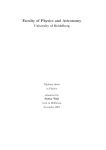
1.3
PRODUCT FUNCTIONAL OVERVIEW
The circuit supports a number of Microchip 8-pin microcontrollers to meet varying
functional and cost factors.
The printed circuit board also is laid out to provide In-Circuit Serial Programming™
(ICSP™) for end-of-line software trimming, for LED binning and color adjustment.
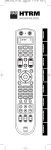
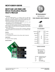
Figure 1-1 illustrates the LED lighting module.
FIGURE 1-1:
INTERIOR AMBIENT LIGHTING MODULE WITH LIN
INTERFACE BLOCK DIAGRAM
MCP2021-500
Network
LIN/J2602
Bus
Transceiver
Red LED
PIC12F615
Green LED
Blue LED
Microcontroller
Intensity (Dimming)
Power
Voltage
Regulator
For information on hardware components of this device, see Chapter 2. “Hardware
Components”.
For information on software components of this device, see Chapter 3. “Software
Components”.
For a detailed flowchart of the LIN handler, see Appendix A. “Schematic for the PC
Board”.
1.4
PRODUCT SALES AND PACKAGING
This product comes with:
• The PC board – (see Figure A-1)
• The firmware (see Table 3-1)
Note:
The firmware files are located on the included software CD-ROM and are
located in a directory called Source.
The PDF files for additional reference are on the software CD.
© 2008 Microchip Technology Inc.
DS51714A-page 6
INTERIOR AMBIENT LIGHTING MODULE
WITH LIN INTERFACE USER’S GUIDE
Chapter 2. Hardware Components
2.1
HARDWARE COMPONENTS
This chapter lists and describes the PC board hardware. The following topics are
described:
•
•
•
•
Microcontroller
Network Interface
Power Supply
Connectors
For a detailed illustration of the PC board, see Appendix A. “Schematic for the PC
Board”.
2.1.1
Microcontroller
The PC board is supplied with the PIC12F615 microcontroller and a MCP2021-500 LIN
transceiver with voltage regulator.
The alternative microcontroller devices and their advantages are:
• PIC12F683 – More program and data memory plus EEPROM
• PIC12F609 – Lower cost without hardware PWM
For applications requiring more I/O pins or additional features, the software can be
ported to higher pin count devices. It is also expandable to drive more LED channels
with additional I/O ports.
Table 2-1 lists the I/O port connections.
TABLE 2-1:
I/O CONNECTIONS
PORT Pin
Function
Notes
Output
RA0
Green LED Drive Output
ICSP™ Data
RA1
Blue LED Drive Output
ICSP Clock
RA2
Intensity Drive Output
CCP Out
Red LED Output
—
RA4
Network Transceiver
RA3
LIN RX Input
ICSP MCLR
RA5
LIN TX Output
—
Note:
The microcontroller Flash program and E2 data memory (E2 is available in
PIC12F683) may be programmed through the five test points located on
the edge of the PC board. These test points are ordered so that they are
pin out compatible with PICkit™ 1 and 2 programmers. Alternatively,
Microchip MPLAB® ICD 2 may be used with an appropriately pinned cable
(not supplied).
For more information, refer to “PIC12F609/HV609, PIC12F615/HV615 Data Sheet”
(DS41302) and “PIC12F683 Data Sheet” (DS41211) available on the Microchip
web site.
© 2008 Microchip Technology Inc.
DS51714A-page 7
Hardware Components
2.1.2
Network Interface
An MCP2021-500 LIN bus transceiver connects to a LIN or J2602 compatible network.
The MCP2021 also contains a voltage regulator that outputs 5.0 VDC. A Zener diode
protects the LIN bus pin from transient voltages. The capacitor between the LIN bus pin
and ground should have its value adjusted to the particular network topology.
For more information on the LIN transceiver, refer to the “MCP202X LIN Transceiver
with Voltage Regulator” (DS22018).
2.1.3
Power Supply
The board gets the power supply and the bus connection through three through-hole
pads. The voltage should be in the range of 8-18 VDC. The MCP2021-500 transceiver’s
integrated, automotive grade voltage regulator is reverse battery, transient and load
dump protected.
2.1.4
Connectors
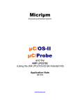
Figure 2-1 illustrates the system connector and Figure 2-2 illustrates the programming
connector.
FIGURE 2-1:
SYSTEM CONNECTOR
+12 VDC VBAT
1
LIN Bidirectional Bus
2
Chassis GND
3
Note: Pin 1 denoted by square pad.
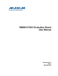
FIGURE 2-2:
PROGRAMMING CONNECTOR
MCLR
1
VCC
VSS
2
3
ICSPDAT
4
ICSPCLK
5
Note: Pin 1 denoted by semi-square pad.
© 2008 Microchip Technology Inc.
DS51714A-page 8
INTERIOR AMBIENT LIGHTING MODULE
WITH LIN INTERFACE USER’S GUIDE
Chapter 3. Software Components
3.1
SOFTWARE COMPONENTS
This chapter lists and describes the firmware components in this device and is
composed of:
• Software Module Overview – The individual files that make up the firmware.
• Local Interconnect Network (LIN) – LIN is a single-wire, serial communications
protocol based on the common asynchronous byte word interface.
• Command Message Frame – LIN identifiers.
• LIN Slave Protocol Handler – This complies to the LIN 2.0 protocol.
The displayed color of the three-element RGB LEDs is controlled by varying the
brightness of the individual LEDs with three software Pulse-Width Modulator (PWM)
outputs. The overall intensity of all three LEDs is set by the hardware PWM output.
For detailed information, refer to the Microchip application note AN1074, “Software
PWM Generation for LED Dimming and RGB Color Applications” (DS01074).
The function of the firmware is:
• Based on the internal 8 MHz oscillator
• Interrupt driven Pulse-Width Modulation routine
- Frequency of 976 Hz PWM
- Color resolution of 8 bits
• LED brightness, controlled by hardware PWM generated by the on-chip
Capture/Compare/PWM module
- Frequency of 3968 Hz PWM
- Brightness resolution of 10 bits
• Ramp up and ramp down dimming functions
- Range of 0 to 65 seconds
- Resolution of 1 ms
3.1.1
Software Module Overview
Table 3-1 lists and describes the basic modules of this software.
TABLE 3-1:
BASIC SOFTWARE MODULE
Module
Description
BBSLAVE.asm
LIN handler/driver slave task routines.
IDTABLE.inc
LIN identifier descriptor table.
RGB615_xxxxxx.asm
Initialization and main program.
© 2008 Microchip Technology Inc.
DS51714A-page 9
Software Components
The software includes two assemble time conditional options:
1. Select the microcontroller, PIC12F615 or PIC12F683, by removing the comment
semicolon in front of one of the two lines of code shown below:
#define proc 12F615; remove comment semi-colon to select processor.
#define proc 12F683;
2. Select the lighting zone number.
Note:
The software provides for any combination of four zones.
#defineZone0; comment out those zones not to be responded to.
; #defineZone1
; #defineZone2
; #defineZone3
Local Interconnect Network (LIN)
3.1.2
The size of a LIN network is restricted to a maximum of 16 nodes (one master and
fifteen slaves). The clock synchronization, the simplicity of UART communication and
the single-wire medium are the major factors for the cost efficiency of LIN.
For more information on the LIN communications protocol, refer to Microchip
application note AN729 “LIN Protocol Implementation Using PICmicro® MCUs”
(DS00729).
The firmware in the LED lighting module has been optimized for a baud rate of 10417.
This is the standard bit rate advocated by SAE J2602.
3.1.3
Command Message Frame
The firmware responds to the following two LIN identifiers:
• Command Frame
• Status Request Frame
3.1.3.1
COMMAND FRAME
ID Byte provides the functional ID bits, and Register 3-2 to Register 3-7 provide the
command format.
REGISTER 3-1:
ID BYTE
Parity
ID Number
bit7
bit 6
bit 5
bit 4
bit 3
bit 2
bit 1
bit 0
1
0
1
0
0
0
1
1
bit 7-6
Parity: As Defined in the LIN Specification
bit 5-0
ID Number: Ambient Light ID 0x23
© 2008 Microchip Technology Inc.
DS51714A-page 10
Interior Ambient Lighting Module with LIN Interface User’s Guide
FIRST DATA BYTE (CONTROL)(1)
REGISTER 3-2:
DIMDWN
RAMPUP
(Reserved)
bit 7
bit 6
bit 5
x
x
0
Select Intensity
bit 4
bit 3
bit 2
bit 1
bit 7
DIMDWN: Dim Down to Zero From Intensity Selected by bits<4:0>
1 = Dim out
0 = No dim
bit 6
RAMPUP: Ramp Up From Zero to Intensity Selected by bits<4:0>
1 = Ramp up
0 = No ramp
bit 5
Reserved
bit 4-0
INTENS<4:0>: Select Intensity
00000 (off) through 11111 (maximum intensity)
Note 1:
bit 0
0 to 0x1F
The first data byte selects the overall intensity of the RGB LEDs, and also sets a
request to ramp up to the chosen intensity, or to ramp down from that intensity
level, to zero. The intensity value is scaled to 10 bits of resolution with an
increment of 16 bits. The intensity value can be in the range of 0 to 63.
REGISTER 3-3:
SECOND DATA BYTE (RED)(1)
Red Saturation
bit 7
bit 6
bit 5
bit 4
bit 3
bit 2
bit 1
bit 0
0 to 0xFF
bit 7-0
Note 1:
RED<7:0>
The second data byte selects the level of red for the desired color mix. The
intensity value can be in the range of 0 to 255.
REGISTER 3-4:
THIRD DATA BYTE (GREEN)(1)
Green Saturation
bit 7
bit 6
bit 5
bit 4
bit 3
bit 2
bit 1
bit 0
0 to 0xFF
bit 7-0
Note 1:
GREEN<7:0>
The third data byte selects the level of green for the desired color mix. The
intensity value can be in the range of 0 to 255.
REGISTER 3-5:
FOURTH DATA BYTE (BLUE)(1)
Blue Saturation
bit 7
bit 6
bit 5
bit 4
bit 3
bit 2
bit 1
bit 0
0 to 0xFF
bit 7-0
Note 1:
DS51714A-page 11
BLUE<7:0>
The fourth data byte selects the level of blue for the desired color mix. The intensity
value can be in the range of 0 to 255.
© 2008 Microchip Technology Inc.
Software Components
FIFTH DATA BYTE (ZONE)(1)
REGISTER 3-6:
(Reserved)
Zone Selection
bit 7
bit 6
bit 5
bit 4
bit 3
bit 2
bit 1
bit 0
0
0
0
0
ZONE3
ZONE2
ZONE1
ZONE0
bit 7-4
Reserved
bit 4-0
ZONE<3:0>: Zone Select
0000 = No zones
0001 = Zone 1
0010 = Zone 2
0011 = Zone 1 and 2
0100 = Zone 3
0101 = Zone 1 and 3
0110 = Zone 2 and 3
0111 = Zone 1, 2 and 3
1000 = Zone 4
1001 = Zone 4 and 1
1010 = Zone 4 ad 2
1011 = Zone 4, 1 and 2
1100 = Zone 4 and 3
1101 = Zone 4, 1 and 3
1110 = Zone 4, 2 and 3
1111 = All zones
Note 1:
The fifth byte selects a particular zone that is to respond to this message. Each of
four bits represents a zone; thus, four zones are defined. Zones can be individually
addressed or in any combination.
REGISTER 3-7:
SIXTH DATA BYTE (CHECKSUM)
Checksum
bit 7
bit 6
bit 7-0
bit 5
bit 4
bit 3
bit 2
bit 1
bit 0
Checksum<7:0>: Checksum of Data Bytes as Defined in the LIN Specification
Table 3-2 lists some typical command frames.
TABLE 3-2:
COMMAND FRAME BIT VALUES
Red%
Green
%
Blue
%
Zone
Color
100
50
50
50
1
White
50
100
0
0
2
Red
Frame
ID
Intensity%
2 3 1F 8 0 8 0 8 0 0 15 E
23
2 3 1 0 FF 0 0 0 0 0 2 ED
23
2 3 5 0 0 0 FF 0 0 0 4 AB
23
Ramp from 0 to 50
0
100
0
3
Green
2 3 9 8 0 0 0 0 FF 0 7 6 0
23
Ramp from 75 to 0
0
0
100
3
Blue
2 3 0 8 8 0 8 0 0 0 0 8 EE
23
25
50
50
0
4
Amber
2 3 1F 0 0 8 0 8 0 0F D 0
23
100
0
50
50
All
Cyan
© 2008 Microchip Technology Inc.
DS51714A-page 12
Interior Ambient Lighting Module with LIN Interface User’s Guide
3.1.3.2
STATUS REQUEST FRAME
Register 3-8 lists the status request frame format.
REGISTER 3-8:
STATUS REQUEST
Parity
ID Number
bit7
bit 6
bit 5
bit 4
bit 3
bit 2
bit 1
bit 0
1
0
1
0
0
1
0
0
bit 7-6
Parity: As Defined in the LIN Specification
bit 5-0
ID Number: Ambient Light Status ID 0x24
The response to a status request is four bytes followed by a checksum. The four bytes
returned are not defined by this version of code.
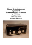
3.1.4
LIN Slave Protocol Handler
The LIN handler routine is illustrated in Figure B-1. This code includes:
•
•
•
•
LIN 2.0 compatible slave interface
USART function is software-based (bit-bang)
Break characters are detected and validated for length
Baud rate is measured and the register values are calculated based on the
incoming Sync character
If either the Break or Sync character causes an error, or the identifier is not listed in the
table, an error condition is flagged.
With a valid Break Sync header, the process of the LIN handler routine continues:
1. The identifier byte is passed through an ID look-up table to check applicability to
this slave.
2. The message length is extracted from the look-up table.
3. The look-up table supplies a bit to determine whether this message data field is
supplied or will be consumed.
4. The received data is stored in a buffer.
5. The identifier parity bits and the message frame checksum are checked.
Or:
4. The transferable data is taken from the buffer and transmitted.
5. The appropriate checksum is generated.
3.1.4.1
PROPOSED SOFTWARE ENHANCEMENT
Some enhancements that can easily be implemented to the LIN handler:
• Although various types of errors are detected, none are accumulated.
- For additional error reporting, error counters could be added.
• Transmitted data bit testing is not done.
- This could be added at point ‘A’ marked in the LIN handler flowchart. Bus
errors, thus detected, can be accumulated and reported.
• The usage of the internal timer/counter to determine bus time-out and Idle
conditions.
DS51714A-page 13
© 2008 Microchip Technology Inc.
Software Components
NOTES:
© 2008 Microchip Technology Inc.
DS51714A-page 14
INTERIOR AMBIENT LIGHTING MODULE
WITH LIN INTERFACE USER’S GUIDE
Appendix A. Schematic for the PC Board
A.1
HIGHLIGHTS
This appendix provides a detailed schematic for getting started using the Interior
Ambient Lighting Module with LIN Interface.
A.1.1
Schematic for the PC Board
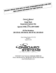
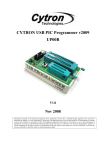
Figure A-1 illustrates the schematic.
FIGURE A-1:
PC BOARD SCHEMATIC
OSRAM LRTBG6TG
TP2
VBAT
6
C3
5
R2
GREENdrv
R3
REDdrv
250
BLUEdrv
1
TP3
5
3
2
1
6
LED1
Inverted OD
Q1
NUD3112
1.0 MF
VDD
CS/WAKE
LIN
TX
RX
FAULT/TXE
GND
250
4
C2
U2
2
4
1
8
R4 1K
MCP2021-500
220 pF
© 2008 Microchip Technology Inc.
U1
1
1N4750 27V
LIN bus
D2
3
7
VBAT
2.2 MF
J1
GND
1
250
VCC
C1
1N4004
1
2
3
1
TP4
ң
D1
TP5
R1
7
6
5
4
3
2
GP0/CIN+/AN0
GP1/CIN-/AN1/VREF
GP2/AN2/T0CKI/COUT/INT/CCP1
GP3/MCLR
GP4/AN3/T1G/OSC2/CLKOUT
GP5/T1CKI/OSC1/CLKIN
PIC12F615
TP1
DS51714A-page 15
Interior Ambient Lighting Module with LIN Interface User’s Guide
NOTES:
DS51714A-page 16
© 2008 Microchip Technology Inc.
INTERIOR AMBIENT LIGHTING MODULE
WITH LIN INTERFACE USER’S GUIDE
Appendix B. LIN Handler Flowchart
B.1
HIGHLIGHTS
This appendix provides a detailed flowchart for getting started using the Interior
Ambient Lighting Module with LIN Interface.
B.1.1
LIN Handler Flowchart
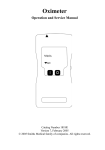
Figure B-1 illustrates the flowchart.
© 2008 Microchip Technology Inc.
DS51714A-page 17
Interior Ambient Lighting Module with LIN Interface User’s Guide
FIGURE B-1:
LIN HANDLER FLOWCHART
LIN_HANDLER
Entered by an Interrupt-On-Change (falling edge)
NO
Break char
done?
NO
Break length
< 10 tbits?
YES
Measure Length of Each
bit in Sync Char
RETURN
BREAK ERROR
Calculate Baud Rate
and Store in Counter
Stop bit
received?
NO
YES
Next char
received?
NO
Calculate
Parity bits and Store
YES
ID = Char
Is ID
valid?
Calculate
Checksum and Store
NO
RETURN
ID ERROR
Transmit Next
Data From Buffer
YES
Decrement
MESSAGE_COUNTER
MESSAGE_COUNTER
= Data Length + 1
Receive
frame?
NO
MESSAGE_COUNTER
=0?
YES
YES
Next char
received?
YES
Put Data into
Receive Buffer
NO
RETURN
OK
NO
MESSAGE_COUNTER
= 0?
YES
ID parity bits
OK?
NO
Decrement
MESSAGE_COUNTER
DS51714A-page 18
NO
RETURN
PARITY ERROR
YES
Checksum
OK?
YES
NO
RETURN
CHECKSUM ERROR
© 2008 Microchip Technology Inc.
INTERIOR AMBIENT LIGHTING MODULE
WITH LIN INTERFACE USER’S GUIDE
Index
A
L
Algorithm .................................................................... 9
Alternative Microcontroller Devices............................ 7
Assemble Time Conditional Options ........................ 10
Automotive Interior Ambient Lighting Module ............ 5
LIN.............................................................................. 9
LIN Communications Protocol.................................. 10
B
Basic Software Modules ............................................ 9
Baud Rate ................................................................ 10
Block Diagrams
Interior Ambient Lighting with LIN Interface ........ 6
C
Command Message Frame...................................... 10
Customer Notification Service.................................... 4
Customer Support ...................................................... 4
D
Documentation
Conventions ........................................................ 2
Layout ................................................................. 1
F
Features ..................................................................... 5
Firmware Function ..................................................... 9
Flowchart
LIN Handler....................................................... 18
H
Hardware Components .............................................. 7
I
I/O Connections ......................................................... 7
Interior Ambient Lighting Module ............................... 5
Internet Address......................................................... 3
M
Microchip Internet Web Site ....................................... 3
P
Packaging .................................................................. 6
PWM .......................................................................... 9
R
Reading, Recommended ........................................... 3
Readme...................................................................... 3
Registers
Fifth Data Byte .................................................. 12
First Data Byte .................................................. 11
Fourth Data Byte............................................... 11
ID Byte .............................................................. 10
Second Data Byte ............................................. 11
Sixth Data Byte ................................................. 12
Status Request ................................................. 13
Third Data Byte ................................................. 11
S
Schematic
PC Board .......................................................... 15
Software Components................................................ 9
T
Transceiver ................................................................ 8
V
Voltage Regulator ...................................................... 8
W
Warranty Registration ................................................ 3
WWW Address........................................................... 3
© 2008 Microchip Technology Inc.
DS51714A-page 19
WORLDWIDE SALES AND SERVICE
AMERICAS
ASIA/PACIFIC
ASIA/PACIFIC
EUROPE
Corporate Office
2355 West Chandler Blvd.
Chandler, AZ 85224-6199
Tel: 480-792-7200
Fax: 480-792-7277
Technical Support:
http://support.microchip.com
Web Address:
www.microchip.com
Asia Pacific Office
Suites 3707-14, 37th Floor
Tower 6, The Gateway
Harbour City, Kowloon
Hong Kong
Tel: 852-2401-1200
Fax: 852-2401-3431
India - Bangalore
Tel: 91-80-4182-8400
Fax: 91-80-4182-8422
India - New Delhi
Tel: 91-11-4160-8631
Fax: 91-11-4160-8632
Austria - Wels
Tel: 43-7242-2244-39
Fax: 43-7242-2244-393
Denmark - Copenhagen
Tel: 45-4450-2828
Fax: 45-4485-2829
India - Pune
Tel: 91-20-2566-1512
Fax: 91-20-2566-1513
France - Paris
Tel: 33-1-69-53-63-20
Fax: 33-1-69-30-90-79
Japan - Yokohama
Tel: 81-45-471- 6166
Fax: 81-45-471-6122
Germany - Munich
Tel: 49-89-627-144-0
Fax: 49-89-627-144-44
Atlanta
Duluth, GA
Tel: 678-957-9614
Fax: 678-957-1455
Boston
Westborough, MA
Tel: 774-760-0087
Fax: 774-760-0088
Chicago
Itasca, IL
Tel: 630-285-0071
Fax: 630-285-0075
Dallas
Addison, TX
Tel: 972-818-7423
Fax: 972-818-2924
Detroit
Farmington Hills, MI
Tel: 248-538-2250
Fax: 248-538-2260
Kokomo
Kokomo, IN
Tel: 765-864-8360
Fax: 765-864-8387
Los Angeles
Mission Viejo, CA
Tel: 949-462-9523
Fax: 949-462-9608
Santa Clara
Santa Clara, CA
Tel: 408-961-6444
Fax: 408-961-6445
Toronto
Mississauga, Ontario,
Canada
Tel: 905-673-0699
Fax: 905-673-6509
Australia - Sydney
Tel: 61-2-9868-6733
Fax: 61-2-9868-6755
China - Beijing
Tel: 86-10-8528-2100
Fax: 86-10-8528-2104
China - Chengdu
Tel: 86-28-8665-5511
Fax: 86-28-8665-7889
Korea - Daegu
Tel: 82-53-744-4301
Fax: 82-53-744-4302
China - Hong Kong SAR
Tel: 852-2401-1200
Fax: 852-2401-3431
Korea - Seoul
Tel: 82-2-554-7200
Fax: 82-2-558-5932 or
82-2-558-5934
China - Nanjing
Tel: 86-25-8473-2460
Fax: 86-25-8473-2470
Malaysia - Kuala Lumpur
Tel: 60-3-6201-9857
Fax: 60-3-6201-9859
China - Qingdao
Tel: 86-532-8502-7355
Fax: 86-532-8502-7205
Malaysia - Penang
Tel: 60-4-227-8870
Fax: 60-4-227-4068
China - Shanghai
Tel: 86-21-5407-5533
Fax: 86-21-5407-5066
Philippines - Manila
Tel: 63-2-634-9065
Fax: 63-2-634-9069
China - Shenyang
Tel: 86-24-2334-2829
Fax: 86-24-2334-2393
Singapore
Tel: 65-6334-8870
Fax: 65-6334-8850
China - Shenzhen
Tel: 86-755-8203-2660
Fax: 86-755-8203-1760
Taiwan - Hsin Chu
Tel: 886-3-572-9526
Fax: 886-3-572-6459
China - Wuhan
Tel: 86-27-5980-5300
Fax: 86-27-5980-5118
Taiwan - Kaohsiung
Tel: 886-7-536-4818
Fax: 886-7-536-4803
China - Xiamen
Tel: 86-592-2388138
Fax: 86-592-2388130
Taiwan - Taipei
Tel: 886-2-2500-6610
Fax: 886-2-2508-0102
China - Xian
Tel: 86-29-8833-7252
Fax: 86-29-8833-7256
Thailand - Bangkok
Tel: 66-2-694-1351
Fax: 66-2-694-1350
Italy - Milan
Tel: 39-0331-742611
Fax: 39-0331-466781
Netherlands - Drunen
Tel: 31-416-690399
Fax: 31-416-690340
Spain - Madrid
Tel: 34-91-708-08-90
Fax: 34-91-708-08-91
UK - Wokingham
Tel: 44-118-921-5869
Fax: 44-118-921-5820
China - Zhuhai
Tel: 86-756-3210040
Fax: 86-756-3210049
01/02/08
DS51714A-page 20
© 2008 Microchip Technology Inc.