1
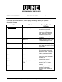
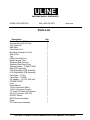
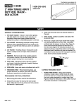
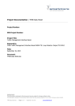
ULINE
SHIPPING SUPPLY SPECIALISTS
PHONE 1-800-295-5510
FAX 1-800-295-5571
uline.com
Set-up Instructions
For H-754, H-755, H-756 & H-757 Low Profile Floor Scale
Your floor scale was shipped with the scale feet used as overload stops. The
feet on your scale are screwed up through the load cells against the deck plate to
protect the load cells during shipment.
Simply screw the feet down three turns by hand and level the scale by additional
adjusting of the feet. You should have firm contact on all four feet.
Plug the TI-500E instrument cable connector into the digital weight indicator.
This cable is located in the floor scale side access compartment. To access the
instrument cable with connector, remove the two screws from the side access cover
plate, and then remove the cover plate. You will find a heavy-duty red cable inside the
compartment. Route the cable from the inside, through the opening in the backside of
this compartment and out from under the scale to your digital weight indicator.
Note: Do not open the gray ABS Junction Box that is also located in this compartment.
Plug the 110V power plug from the digital weight indicator into a wall socket.
Turn the power switch on the backside of the digital weight indicator to the on position.
You are now ready to weigh. Reinstall the side access cover plate.
Do not calibrate the scale, it has been calibrated at the factory to meet or
exceed H-44 specifications.
CHICAGO • ATLANTA • DALLAS • MINNEAPOLIS • LOS ANGELES • NYC/PHILA
ULINE
SHIPPING SUPPLY SPECIALISTS
PHONE 1-800-295-5510
FAX 1-800-295-5571
uline.com
Troubleshooting Information
Should shipping screws be removed from the scale base before the scale is put
into use?
Yes. The shipping screws are put into place to protect the scale from damage during
shipping. They should be removed prior to use.
The scale is reading negative weights.
This occurs when the feet have not been screwed down after receiving the scale.
My display module doesn't work.
The module must be plugged into the wall socket, the adapter must be plugged into the
module and the module switch must be turned on.
The scale works well when the sample is placed on the edge, but not when it is
placed in the middle of the scale.
The scale may not be leveled properly. All four feet must be sitting on the floor.
Calibration Overview
The scale is delivered Pre-Calibrated. There is no need to calibrate the scale unless
you feel it has become inaccurate. It is recommended that this scale be calibrated by
an authorized dealer.
CHICAGO • ATLANTA • DALLAS • MINNEAPOLIS • LOS ANGELES • NYC/PHILA
ULINE
SHIPPING SUPPLY SPECIALISTS
PHONE 1-800-295-5510
FAX 1-800-295-5571
uline.com
ERROR MESSAGES:
If the scale encounters an error, it will display a message alerting the operator. A
description follows:
Code
Mode
Normal Operating Mode
Err 0
Span Calibration
Mode (F17)
ERR 1
Span Calibration
Mode (F17)
ERR 2
Span Calibration
Mode (F17)
ERR 3
All Modes
ERR 4
All Modes
ERR 5
Key-in Span Calibration Mode
(F20)
ERR 7
Initialization
Meaning/Possible
Solution
Gross Overload. A weight
greater than the scale capacity
has been put on the scale.
Remove the weight from the
platter or try recalibrating the
scale. Otherwise, check for a
bad load cell connection or
possible load cell damage due to
overloading
Keyed-in weight value is larger
than the full scale capacity. Use
a smaller test weight or check
keyed-in value.
Keyed-in weight value is less
than 1% of full scale capacity.
Use a larger test weight or check
keyed-in value.
There is not enough load cell
signal to produce the internal
counts necessary to properly
calibrate the scale. First check
all load connections. Use F16
mode to view internal counts.
Non-volatile memory read error.
One or more setup parameters
have been lost.
Non-volatile memory write error.
Indicator needs service.
You have attempted to enter a
zero value for C1. Enter a
known calibration value greater
than zero.
No reading from the ADC. Make
sure there is a load cell
connected to the indicator at
start-up
CHICAGO • ATLANTA • DALLAS • MINNEAPOLIS • LOS ANGELES • NYC/PHILA
ULINE
SHIPPING SUPPLY SPECIALISTS
PHONE 1-800-295-5510
FAX 1-800-295-5571
uline.com
Parts List
Description
Rubber Boot for DC Power Jack
Housing Screw Kit (12 Pcs)
2.5K Load Cell
ABS-JBox
Floor Scale Foot
Mounting Hardware for L/C’s
Side Cover
Tag
Plastic Housing-Front
Metal Housing- Rear
Stainless Steel Housing
Stainless Steel Rear Cover
Stainless Stand – TI 500/TI 500E
Main PCB Assembly
LED Display/Key PCB Assembly
LCD Display/Key PCB Assembly
Face Plate – TI 500
Face Plate – TI 500E
AC Adapter – 12 VCD, 500 mA F
EPROM 27E257
Lens
Knob1Manual
14-Pin Centronics (Male)
14-Pin Centronics (Female)
15" Load Cell Cable w/Connector
9-Pin D Connector (RS-232)
ON/OFF Switch
NTEP Switch Assembly
Gland
CD Power Jack Assembly
Qty.
1
1
1
1
1
1
1
1
1
1
1
1
1
1
1
1
1
1
1
1
1
1
1
1
1
1
1
1
1
1
CHICAGO • ATLANTA • DALLAS • MINNEAPOLIS • LOS ANGELES • NYC/PHILA