1
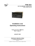
TFM-556
VHF High/VHF Low/UHF MULTI-BAND FM
AIRBORNE TRANSCEIVER
Installation and
Operating Instructions
TiL Document No. 03RE328
Revision N/C Issue 2
SEPTEMBER 2003
Technisonic Industries Limited
240 Traders Boulevard, Mississauga, Ontario L4Z 1W7
Tel: (905) 890-2113 Fax: (905) 890-5338
www.til.ca
Copyright by Technisonic Industries Limited. All rights reserved.
REVISION HISTORY
[ 03RE328 ]
REV
SECTION
- PAGE -
DESCRIPTION
REV n/c
issue 1
Issue 2
DATE
EDITED BY
SEP 2003
SEP 2003
Global
3-4,3-5
New document template, Title page changed,
Added Headers/Footers, Rev page, Warranty pg
Split Fig 3.2 to make it bigger, easier to read.
& change item 1 TFM-550 to TFM-556
i
APR 2012
FM
ii
CAUTION ! STATIC SENSITIVE !
This unit contains static sensitive devices. Wear a grounded wrist strap and/or conductive
gloves when handling printed circuit boards.
FCC COMPLIANCE INFORMATION
This equipment has been tested and found to comply with the limits for a Class A digital device,
pursuant to Part 15 of the FCC Rules. These limits are designed to provide reasonable protection
against harmful interference when the equipment is operated in a commercial environment. This
equipment generates, uses, and can radiate radio frequency energy and, if not installed and used in
accordance with the instruction manual, may cause harmful interference to radio communications.
Operation of this equipment in a residential area is likely to cause harmful interference in which
case the user will be required to correct the interference at his/her own expense.
WARNING
Changes or modifications not expressly approved by Technisonic Industries could void the user’s
authority to operate the equipment.
IMPORTANT:
The TFM-556 transceiver is designed for airborne use. It is certified by Industry Canada under
aeronautical standard RSS 141 as amended. The equipment is not permitted to be installed in a
fixed or mobile, land based station in Canada.
WARRANTY INFORMATION
The Model TFM-556 Transceiver is under warranty for one year from date of purchase.
Failed units caused by defective parts, or workmanship should be returned to:
Technisonic Industries Limited
240 Traders Boulevard
Mississauga, Ontario L4Z 1W7
Tel: (905) 890-2113
Fax: (905) 890-5338
iii
Summary of DO-160C Environmental Testing
Summary of DO-160C Environmental Testing for Technisonic Model TFM-556, Low-band VHF,
High-band VHF and UHF Transceiver:
Conditions
Section
Description of Conducted Tests
Temperature and Altitude
Vibration
4.0
8.0
Magnetic Effect
Power Input
Voltage Spike
RF Emission
15.0
16.0
17.0
21.0
Equipment tested to categories B2 and D1.
Equipment is tested without shock mounts to categories
B, M and N.
Equipment is class A.
Equipment tested to category B.
Equipment tested to category B.
Equipment tested to category Z.
Installation Approval Note
Presently no TSO standard exists for airborne FM transceivers. To make it easier for installation
agencies to provide their customers with an approved installation supported by an effective
Airworthiness Approval, Technisonic has secured Supplemental Type Certificate (STC) Approvals
(both US and Canadian) on its Airborne FM products for many helicopters currently being delivered
in the US and Canada as well as a number of single engine fixed wing aircraft. The above
referenced DO-160C test data is also on file and available from Technisonic to support approval
requirements in airframes for which Technisonic does not possess an STC.
Approved aircraft types are listed in the attachments to the formal STC documents. These STCs are
the exclusive property of Technisonic and require the written authority of Technisonic for their use.
To assist Factory Authorized Technisonic Dealers in the certification process, we have placed
copies of our Canadian and US STCs on our web site along with a letter of authorization for their
use. These documents may be downloaded and used as support for the technical submission to
FAA or Transport Canada. Only factory authorized dealers/installers are permitted to download and
make use of these documents on behalf of their customers (end users) in support of regulatory
agency approval. Please refer to the Technisonic web site www.til.ca for the latest issue of
available STCs and letter of authorization for use.
iv
TECHNISONIC INDUSTRIES LIMITED
www.til.ca
TABLE OF CONTENTS
SECTION
SECTION 1
1.1
1.2
1.3
1.4
1.5
GENERAL DESCRIPTION
1-1
1-1
1-1
1-1
1-2
OPERATING INSTRUCTIONS
FEATURES......................................................................................................
OPERATING INSTRUCTIONS ............................................................................
PROGRAMMING INSTRUCTIONS ......................................................................
PRIORITY AND SELECTIVE MEMORY CHANNEL SCANNING ................................
SCANNING FUNCTION ....................................................................................
DIRECT FREQUENCY ENTRY MODE ..................................................................
RECEIVE FREQUENCY SIMPLEX FUNCTION .......................................................
KEYBOARD LOCKOUT FUNCTION ....................................................................
VARIABLE FREQUENCY MODE FUNCTION ........................................................
LED DISPLAY VARIABLE DIMMING MODE .........................................................
90 SECOND TRANSMITTER TIMEOUT FEATURE ................................................
PROGRAMMING CTCSS TONES AND DPL CODES ..............................................
CROSS BAND REPEAT ....................................................................................
PC MEMORY/PROGRAMMING DOWNLOAD CAPABILITY .....................................
SECTION 3
3.1
3.2
3.3
3.4
3.5
3.6
3.7
3.7.1
3.7.2
3.7.3
3.7.4
3.7.5
3.7.6
3.7.7
3.7.8
3.7.9
3.8
3.9
PAGE
INTRODUCTION .............................................................................................
DESCRIPTION ................................................................................................
PURPOSE OF EQUIPMENT ...............................................................................
MODEL VARIATION ........................................................................................
TECHNICAL CHARACTERISTICS ......................................................................
SECTION 2
2.1
2.2
2.3
2.4
2.5
2.6
2.7
2.8
2.9
2.10
2.11
2.12
2.13
2.14
TITLE
2-1
2-3
2-4
2-4
2-5
2-5
2-5
2-6
2-6
2-6
2-6
2-6
2-8
2-8
INSTALLATION INSTRUCTIONS
GENERAL ......................................................................................................
EQUIPMENT PACKING LOG .............................................................................
TRANSCEIVER INSTALLATION .........................................................................
INSTALLATION KIT - CONTENTS .....................................................................
ANTENNA INSTALLATION ...............................................................................
INSTALLATION - PIN LOCATIONS AND CONNECTIONS ......................................
WIRING INSTRUCTIONS ..................................................................................
Main Power +28VDC .....................................................................................
Main Ground ..................................................................................................
PTT (Ground Keying) .......................................................................................
Front Panel Back Lighting ................................................................................
Audio Outputs (600 and 4 Ohms) .....................................................................
Audio Output Ground ......................................................................................
Mic Signal Input .............................................................................................
Memory Up/Memory Down ..............................................................................
Data Input .....................................................................................................
INTERNAL PROGRAMMING ENABLE/DISABLE JUMPER .......................................
TRANSMITTER POWER ADJUSTMENTS ............................................................
TFM-556 Installation & Operating Instructions
3-1
3-1
3-1
3-1
3-1
3-1
3-6
3-6
3-6
3-6
3-6
3-6
3-6
3-6
3-6
3-7
3-7
3-8
TiL 03RE328 Rev n/c Issue 2
v
TECHNISONIC INDUSTRIES LIMITED
www.til.ca
3.10
3.11
3.12
TRANSMITTER MICROPHONE LEVEL ADJUSTMENT ...........................................
SQUELCH ADJUSTMENT ................................................................................
TRANSMITTER DEVIATION ADJUSTMENT ........................................................
3-8
3-10
3-10
APPENDIX – POST INSTALLATION EMI TEST ...............................................................
A-1
WARRANTY ................................................................................................................
LIST OF FIGURES
FIGURE
TITLE
PAGE
2.1
2.2
Operator's Switches and Controls .....................................................................
PC Up/Download Cable - Wiring Diagram ...........................................................
2-2
2-9
3.1
3.2
3.3
3.4
3.5
3.6
3.7
Outline Drawing .............................................................................................
Wiring Connections ........................................................................................
Internal Enable/Disable Jumper Locations ...........................................................
External Adjustment Access Holes ....................................................................
VHF Deviation Adjustment Potentiometer Location ..............................................
UHF Deviation Adjustment Potentiometer Location ..............................................
VHF LOW Deviation Adjustment Potentiometer Location ......................................
3-2
3-4
3-7
3-9
3-11
3-12
3-13
LIST OF TABLES
TABLE
3.1
TITLE
PAGE
9-pin D and 15-Pin D Connections ....................................................................
TFM-556 Installation & Operating Instructions
3-3
TiL 03RE328 Rev n/c Issue 2
vi
TECHNISONIC INDUSTRIES LIMITED
www.til.ca
SECTION 1 - GENERAL DESCRIPTION
1.1
INTRODUCTION
This publication provides operating and installation information on the TFM-556 Transceiver.
manufactured by Technisonic Industries Limited. The unit offers an extended frequency
range with selectable channel spacing and is intended for use (in the U.S.) only by
government agencies or contractors thereto, who have obtained licensing for operation in
the 138-150 MHz portion of the VHF band. If the TFM-556 transceiver is used in CANADA,
VHF operation is restricted to the following sub bands: 138-144, 148-148.99, 149.005150.005 and 150.05-174 MHz. Furthermore the TFM-556 is a frequency agile transceiver
which is restricted to airborne use and must not be operated as a base station in Canada.
1.2
DESCRIPTION
The TFM-556, Transceiver is a frequency agile, fully synthesized airborne FM transceiver
capable of operating in the 66 to 88 MHz, 138 to 174 MHz and 403 to 512 MHz frequency
range in 2.5 kHz increments with either 25 kHz or 12.5 kHz channel spacing. The
Transceiver can operate without restriction on any split frequency pair in either band.
The TFM-556 Transceiver provides 200 operator accessible memory positions per band,
each of which is capable of storing a transmit frequency, receive frequency, transmit
frequency CTCSS tone or DPL code, receive frequency CTCSS tone or DPL code, an
alphanumeric identifier for each channel and wideband (25 kHz) or narrowband (12.5 kHz)
channel spacing assignment. Operating frequency and other related data are presented on a
96 character, four line LED matrix display. Data entry and function control are performed via
a 12 button keypad. Preset channels may also be scrolled and scanned (scanning only
possible in VHF high and UHF bands) through keypad function activation. Data may also be
entered via computer with the provided software and optional PC Up/download cable, P/N
993390-1.
1.3
PURPOSE OF EQUIPMENT
The TFM-556, VHF High/VHF Low/UHF Band FM Transceiver is designed to provide
secondary airborne communications to facilitate operations which are typically performed in
a low altitude environment. The transmitter sections of this unit have a minimum of 8 watts
and do not exceed 10 watts output power, which may be reduced by a front panel switch
to 1 watt, in order to reduce interference to land based systems.
1.4
MODEL VARIATION
There are four variations of the Model TFM-556 Transceiver. All units offer identical
features and performance except for the following differences:
TFM-556,
TFM-556,
TFM-556,
TFM-556,
P/N
P/N
P/N
P/N
031219-1
031219-1 (5V)
031219-2
031219-2 (5V)
GREEN display with 28 Volt back lighting.
GREEN display with 5 Volt back lighting.
RED display with 28 Volt back lighting.
RED display with 5 Volt back lighting.
P/N's 991101-1, 991101-2 and 991101-1 NV are always provided with 28 Volt back
lighting unless a specific request is made for 5 Volt AC operation.
TFM-556 Installation & Operating Instructions
TiL 03RE328 Rev n/c Issue 2
1-1
TECHNISONIC INDUSTRIES LIMITED
www.til.ca
1.5
TECHNICAL CHARACTERISTICS
Characteristic
Specification
GENERAL
Model Designation:
TFM-556
Tuning Increments:
66 to 88, 138 to 174
and 403 to 512 MHz
2.5 kHz
Operating Modes:
F3E simplex or semi-duplex
Channel Spacing:
25 or 12.5 kHz
Physical Dimensions (including heatsink):
Approx. 8.0" X 3.75" X 5.75"
Weight:
Approx. 5.1 Lbs (2.3 Kg)
Mounting:
Panel Mount via Dzus fasteners
Operating Temperature Range:
-45°C to +70°C
Frequency Ranges:
Power Requirement:
Voltage:
Current:
28.0 Vdc, ± 15%
Receive - 1.2 A Max.
1 Watt Transmit - 2.2 A Max.
8-10 Watt Transmit - 3.4 A Max.
8-10 Watt Dual Transmit - 5 A Max.
Frequency Selection:
200 memories per band programmed with:
a) Tx Frequency/Rx Frequency
b) Tx/Rx CTCSS tone or DPL code
c) 9 character alpha numeric title
CTCSS squelch/encoder (FM):
All CTCSS tones available
DPL digital squelch/encoder (FM):
All standard DPL codes
DTMF encoder:
All standard DTMF tones
Audio Outputs:
0.5 Watts into 600 ohms
Speaker Output:
2.5 Watts min. into 4 ohms
Back Lighting:
28 Volts (standard) or 5 Volts (specify)
Display Colour:
Green (standard) or Red (specify)
1
DPL is a trademark of Motorola Corporation
TFM-556 Installation & Operating Instructions
TiL 03RE328 Rev n/c Issue 2
1-2
TECHNISONIC INDUSTRIES LIMITED
www.til.ca
1.5
TECHNICAL CHARACTERISTICS (continued)
VHF RECEIVER
FM Sensitivity at 12 dB SINAD
Better than 0.35 μV
AM Sensitivity at 12 dB SINAD
Better than 1.50 μV
Adjacent Channel Selectivity
-75 dB (25 kHz)
-70 dB (12.5 kHz)
Spurious Attenuation
-90 dB
Third Order Intermodulation
-70 dB
Image Attenuation
-80 dB
FM Acceptance
± 6 kHz
Hum and Noise
Better than 45 dB
Audio Distortion
less than 5%
Antenna Conducted Emission
less than -70 dBm
UHF RECEIVER
Sensitivity at 12 dB SINAD
Better than 0.35 μV
Adjacent Channel Selectivity
-70 dB (25 kHz)
-60 dB (12.5 kHz)
Spurious Attenuation
-80 dB
Third Order Intermodulation
-70 dB
Image Attenuation
-60 dB
FM Acceptance
± 6 kHz
Hum and Noise
Better than 40 dB
Audio Distortion
less than 5%
Antenna Conducted Emission
less than -70 dBm
VHF LOW RECEIVER
All specifications identical to VHF receiver.
TFM-556 Installation & Operating Instructions
TiL 03RE328 Rev n/c Issue 2
1-3
TECHNISONIC INDUSTRIES LIMITED
www.til.ca
1.5
TECHNICAL CHARACTERISTICS (continued)
VHF, VHF LOW and UHF TRANSMITTER
RF Power Output
1 watt or 10 watts
Output Impedance
50 ohms
Maximum Deviation
(In narrowband mode)
±5 kHz (25 kHz mode)
±2.5 kHz (12.5kHz mode)
Spurious Attenuation
-90 dB below carrier level
Frequency Stability
±2.5 ppm
Microphone Circuit
Carbon or equivalent
Sidetone Output
Harmonic Attenuation
0.5W (max) into 600 ohms
-60 dB below carrier level
FM Hum And Noise
-40 dB
Audio Input
50 mV at 2.5 kHz into 200 ohms input
circuit for ±3.5 kHz deviation, adjust.
FM Audio Distortion
< 5%
TFM-556 Installation & Operating Instructions
TiL 03RE328 Rev n/c Issue 2
1-4
TECHNISONIC INDUSTRIES LIMITED
www.til.ca
SECTION 2 – OPERATING INSTRUCTIONS
2.1
FEATURES
The equipment has several important operating features which provide maximum flexibility,
performance and versatility. These features include:
1.
2.
3.
4.
5.
6.
7.
8.
9.
10.
11.
12.
13.
14.
The UHF band can be configured to be operated independently of the VHF High and
VHF Low bands or all three bands can operate as a single unit.
The unit can be set up as a cross band repeater, linking a VHF High and UHF
frequency in both directions. The VHF Low band will not cross band repeat.
200 memory positions per band which can each be programmed with a transmit and
receive frequency with 25 or 12.5 kHz channel spacing, Tx/Rx CTCSS tones or DPL
codes and a 9-character alphanumeric title.
Scanning of preprogrammed memories with selective memory scanning, in up to 5
scan lists, for the VHF High or UHF band. The VHF Low band does not scan.
Priority scan of memory channel 1 in VHF high or UHF band. The Scan function can
only be used for one of these bands at a time. Simultaneous scanning on both bands
is not possible.
Direct frequency entry mode.
Receive frequency simplex function. (Repeater talk around)
Switchable RF output power between 1 watt and 8-10 watts.
Lockout of keyboard to prevent inadvertent entries.
Variable frequency mode to manually scan up and down in 1 MHz, 100 kHz or 2.5
kHz steps.
LED display variable dimming mode.
Selectable 90 second Tx time out feature.
PC Memory Upload or Download capability.
Configuration Menu - Pressing ENTER, RCL and FUNC together while turning the
radio on will put it into configuration mode. The programming features affected are:
a)
DPL - Can be turned on or off with the MUP and MDN (4 and 7) keys. This only
removes the DPL entry step from the programming sequence and does not stop
memories that already have DPL codes from working. This also applies to the
rest of the on/off configurable items.
b)
SCAN - Can be disabled. Selecting FUNC and SCAN will do nothing if Scan is
off. The scan list indicator (+) will still display if was previously programmed.
c)
Rx CTCSS - Can be turned on or off from the programming sequence. This
affects only the CTCSS tones for receive.
d)
LAST MEM - If set to on, the last memory channel on the display will be what
comes up when the radio is turned on. If set to off, the last memory that
changes were made to will be what comes up when the unit is switched on.
e)
DUALMODE - If set to ON, the UHF band is operated independently from the 2
VHF bands. (i.e. UHF audio separately available on 9-pin connector). The radio
is shipped with this feature OFF.
TFM-556 Installation & Operating Instructions
TiL 03RE328 Rev n/c Issue 2
2-1
TECHNISONIC INDUSTRIES LIMITED
www.til.ca
f)
REMOTE BS -Only used when an RC-550 slave control head is attached. Setting
this feature on will give the transmit selection to the Band Select switch on the
RC-550 rather than on the radio. This is useful when the operator at the RC-550
is using the VHF high and low bands. Regardless of
whether this feature is set to on or off, the fourth squelch light will light on both
units when both BS switches are set to the same position.
g)
SIDETONE - The TX audio circuit becomes active allowing you to adjust the
sidetone level with the VHF volume knob. When the desired level is reached,
press ENTER and this level will be set for both VHF and UHF bands. The factory
setting is 23.
Note: The sidetone level must be set every time you go through the configuration
menu since it takes the setting of the volume knob regardless of whether you set
it or not.
FIGURE 2.1 Operator’s Switches and Controls
TFM-556 Installation & Operating Instructions
TiL 03RE328 Rev n/c Issue 2
2-2
TECHNISONIC INDUSTRIES LIMITED
www.til.ca
2.2
OPERATING INSTRUCTIONS (See Figure 2.1)
1.
Switch power on by turning the VHF volume clockwise. Depending how the radio is
configured, either the last programmed or last displayed frequencies will appear on
the screen. The transceiver is now in normal operating mode. NOTE: VHF high band
will be referred to as “VHF” and VHF low band as “VLO” in these instructions.
2.
Adjust the audio level by adjusting the VHF, UHF and VLO volume knobs.
3.
Pressing the squelch defeat button will open all receivers to confirm they work.
4.
Read the display. The top line will indicate which VHF memory is selected followed
by a "+" if the memory position is included in a scan list, an alphanumeric message,
and the frequency of the VHF receiver. A small "n" before the frequency indicates
12.5 kHz narrowband channel spacing is in effect on this memory position. In the
receive mode, the frequency is followed by an "RT" if an RX CTCSS tone or RX DPL
code is programmed, or an "RX" if no receive tone/code is programmed. Similarity,
in the transmit mode either a "TT" or "TX" is shown after the frequency. The
second line shows the same information for the UHF band. The third line indicates
the same information about the VHF LOW band.
5.
Set the VHF/UHF/VLO (BS) switch to the desired band.
6.
The VHF/PRI switch is spring loaded and is normally in the VHF position. Pressing
this switch down will result in channel 001 being loaded on the VHF band.
7.
Set the HI/LO switch to the desired RF output power.
8.
Select the desired memory by using the M.UP and M.DN buttons, or the RCL button
and a three digit number followed by ENTER.
9.
To transmit DTMF tones, use the keyboard keys while holding the PTT button on
the microphone. There is a 5 second PTT delay after pressing a key so that you may
press several DTMF keys in sequence without having to hold the PTT. The keyboard
returns to its normal function when the PTT is released.
The display always shows the status of both receivers and the transmitter. The light at the
left of each line indicates which receiver is receiving. The display also indicates the memory
channel is in use. A "TX" (no TX tone/codes programmed) or "TT"(either TX tone or code
programmed) on the right side of the display indicates which band is active when
transmitting. The transmit frequency is also shown. In the receive mode the display shows
“RX” beside the receive frequency if no RX tone or DPL code is programmed and “RT” if a
CTCSS tone or DPL code is programmed.
While in any programming mode, all receivers continue to function. When the transceiver is
in either of the operating frequency or CTCSS tone/DPL code programming modes and you
must respond to a call, click the microphone PTT once (the radio will not transmit during
this click). This will cause the transceiver to revert back to the normal operating mode and
communications with the caller can proceed in the usual fashion. Pressing the FUNC key
has the same effect.
TFM-556 Installation & Operating Instructions
TiL 03RE328 Rev n/c Issue 2
2-3
TECHNISONIC INDUSTRIES LIMITED
www.til.ca
2.3
PROGRAMMING INSTRUCTIONS
To program one of the 200 memory channels in one of the bands:
1.
2.
3.
4.
5.
6.
7.
8.
9.
10.
2.4
Select the desired band on the band select (VHF/UHF/VLO) switch. This is required
before any of the programming modes or functions.
Press the FUNC key. The display will show the function prompt.
Press the PROG key. The display will show the current receive frequency with a
flashing curser on the first or second digit (The first digit is always a one <1> on
the VHF band and there is no hundreds digit on the VHF LOW band).
Type in the desired receive frequency. If you type in a frequency which is not a 2.5
kHz step, the nearest valid frequency will be automatically selected.
The curser will return to the second digit. You can retype the frequency if you have
made an error or press ENTER to continue.
The transmit frequency will be displayed with the curser on the second digit. Follow
the same method as in step 4 and 5.
The channel spacing increment of either 25.0 or 12.5 kHz is now displayed. Use the
M.UP and M.DN keys to select the desired channel spacing for the memory position,
then press ENTER.
The alpha-numeric title is now displayed. Use the M.UP and M.DN keys to scroll
through the alphabet, numbers and symbols. When the desired character is
displayed, press ENTER to advance to the next character. Press “1" to backspace.
Keep repeating step six until the last space is set (there are 9 characters). The
display will show SCAN or LOCKOUT to enable this memory position as part of a
scan list or lock it out of the scan lists. Use the 1,2,3,4,5 and M.DN keys to toggle
between these functions (for details see paragraph 2.5). Once the desired condition
has been selected, press ENTER. The TFM-556’s display will show a "+" beside the
memory channel number if scan is enabled. Note: Scan function and Scan list
feature not provided for VHF Low Band.
The display will now show the current memory number. Type in the 3-digit number
of the memory you want to save to (if different from displayed one) and press
ENTER.
PRIORITY SCANNING, SELECTIVE MEMORY CHANNEL SCANNING & SCAN LISTS
Instead of breaking up the 200 channels into blocks for scanning, the TFM-556 has 5 scan
lists per band (VHF high and UHF only). Any of the 200 channels can be assigned to any
one or more of these 5 scan lists. This means the channels do not have to be repeated for
them to be in more than one block and that you are not limited to the number of channels
that can be scanned at once, since all 200 channels can be put into any scan list. Scanning
is not available on the VHF Low band.
The priority memory channel is always memory position number 1. The priority memory
channel is scanned every other step (i.e. 121314151...) to ensure that no incoming
messages are missed. The priority channel can be locked out, which will result in the normal
scanning of the other memory positions.
Selective memory scanning allows the user to select which of the 200 memory channels are
to be scanned or locked out when the scan function is invoked. To use this feature, follow
PROGRAMMING INSTRUCTIONS found in paragraph 2.3. Once the screen displays SCAN
or LOCKOUT, use the 1,2,3,4,5 or M.DN keys to toggle to the desired condition and press
ENTER. Entering the any or all of the numbers 1,2,3,4 or 5 will include that memory channel
in any of the five scan lists. In normal operating mode the display will later show a "+"
beside the memory channel number if it has been included in any of the 5 scan lists.
TFM-556 Installation & Operating Instructions
TiL 03RE328 Rev n/c Issue 2
2-4
TECHNISONIC INDUSTRIES LIMITED
www.til.ca
2.5
SCANNING FUNCTION (5 second talkback delay)
Select the band you wish to scan with the band switch. (You can not scan VHF Low band).
To start scanning of the memory channels, press FUNC then SCAN and then the number
(1,2,3,4,5) of the desired scan list.
The radio will scan through all the preset memory positions in the selected scan list (see
above paragraph for priority and selective scan features) and will lock on to the first active
channel in the scan sequence. It will remain on the channel until it becomes inactive.
Scanning will resume again after five seconds of inactivity. To exit the scan mode, press
the SCAN key. This will cause the radio to revert back to the normal operating mode.
If while scanning, you hear a call for you:
1.
2.
Respond to the call within 5 seconds. When scanning is interrupted by an incoming
signal, the channel will remain open for five seconds before resuming scanning.
During communications the five second timer is reset from the last Rx or Tx signal
encountered.
The radio resumes scanning once the Rx or Tx activity has ceased for more than five
seconds. The SCAN key must be pressed to exit the scan mode.
2.6
DIRECT FREQUENCY ENTRY MODE
This mode is designed to facilitate quick frequency selection during emergency and other
operational conditions requiring direct operating frequency selection. This operating mode is
disabled along with the programming mode when the internal disable jumper is set.
1.
2.
3.
When the transceiver is in the normal operating mode, press FUNC and the desired
operating frequency i.e. 153.2750.
On the UHF band press FUNC and then 1 and the desired frequency i.e. 443.5500.
You will then be asked for 12.5 or 25.0 kHz channel spacing. Select with MUP or
MDN and press ENTER.
Please note in the above operation, after FUNC and "1" are entered, the LED display will
show memory channel "000" and then the remaining digits in the desired frequency are
shown as they are entered. No alphanumeric message can be entered in this mode.
Operation on the new frequency occurs in both transmit and receive (simplex only) modes.
If RX or TX CTCSS tones/DPL codes are required they must be programmed in afterwards.
2.7
RECEIVE FREQUENCY SIMPLEX FUNCTION (Repeater Talkaround)
The receive frequency simplex function allows you to quickly change the transmit
frequency, when operating on a split pair (repeater/semi-duplex mode), to the receive
frequency to allow direct communications. i.e. If you are transmitting on 152.000 MHz and
receiving 152.555 MHz, select VHF on the band select switch and press FUNC then UP to
transmit on 152.555 MHz. To return to the split pair condition, you must recall the memory
channel again. This is quickly done by pressing M.UP for one step up, then back down one
step with the M.DN key.
TFM-556 Installation & Operating Instructions
TiL 03RE328 Rev n/c Issue 2
2-5
TECHNISONIC INDUSTRIES LIMITED
www.til.ca
2.8
KEYBOARD LOCKOUT FUNCTION
The keyboard can be locked out so that accidental pressing of keys does not change
frequency, etc., unknowingly to the operator. To lock the keyboard, press FUNC then
LOCK. This will disable all keyboard functions (except keyboard unlock) in the receive mode.
The DTMF function during transmit will not be affected. To unlock the keyboard, press and
hold the LOCK key for two seconds until the display indicates "UNLOCK".
2.9
VARIABLE FREQUENCY MODE FUNCTION
To enter variable frequency mode, press RCL, 0,0,0, then ENTER or enter a frequency in the
direct entry mode described above. The memory channel that you were just in will still be
valid but now you can manually adjust the frequency with the M.UP, M.DN, UP and DN
keys. The UP and DN keys will make the frequency count up or down in steps of 2.5 kHz.
The M.UP and M.DN keys will make the frequency count up or down in steps of 1 MHz.
You can not change the label. The frequency in this mode can not be stored in memory. To
exit this mode, recall one of the 200 memory channels (i.e. RCL, 0,0,1). Variable frequency
mode is disabled when the internal entry disable jumper is removed.
2.10
LED DISPLAY VARIABLE DIMMING MODE
1.
2.
2.11
With the transceiver in normal operating mode press the UP or DN keys to increase
or decrease the intensity of the LED display.
Once maximum intensity of the display is achieved, the UP key no longer functions.
Conversely once minimum intensity is reached, the DN key ceases to function.
90 SECOND TRANSMITTER TIME OUT FEATURE
A selectable 90 second transmitter time out feature is provided to prevent accidental
continuous transmission in the event of a faulty PTT switch. With this feature enabled the
transceiver will stop transmitting after the PTT is engaged continuously for 90 seconds. The
timer is reset by releasing then re-engaging the PTT switch.
Press the FUNC then the M.UP key. Use the M.UP and M.DN keys to select 90 SEC, which
enables the feature, or NONE which disables it.
2.12
PROGRAMMING CTCSS TONES AND DPL CODES
CTCSS tones (PL tones) or Digital DPL codes can be assigned to each memory channel on
any of the three operating bands. To program a tone/code to a memory channel:
1.
2.
3.
4.
Select the desired band on the band select switch.
Use the M.UP and M.DN keys to select the memory channel that you want to assign
a CTCSS tone or DPL code.
Press the FUNC key then the TONE key. The display will show "RX TONE:" and the
current tone number, as well as the tone frequency in Hz.
Use the M.UP and M.DN keys to select the tone number you require. The following
is a list of the available CTCSS tones:
TFM-556 Installation & Operating Instructions
TiL 03RE328 Rev n/c Issue 2
2-6
TECHNISONIC INDUSTRIES LIMITED
www.til.ca
The following is a list of the standard CTCSS tones:
Number
Tone
Number
Tone
Number
Tone
01
02
03
04
05
67.0
71.9
74.4
77.0
79.7
26
27
28
29
30
162.2
167.9
173.8
179.9
186.2
51
52
53
54
55
177.3*
183.5*
189.9*
196.6*
199.5*
06
07
08
09
10
82.5
85.4
88.5
91.5
94.8
31
32
33
34
35
192.8
203.5
33.0*
35.4*
36.6*
56
57
58
59
60
206.5*
210.7*
218.1*
225.7*
229.1*
11
12
13
14
15
97.4
100.0
103.5
107.2
110.9
36
37
38
39
40
37.9*
39.6*
44.4*
47.5*
49.2*
61
233.6*
62
241.8*
63
250.3*
64
No Tone
(carrier squelch only)
16
17
18
19
20
114.8
118.8
123.0
127.3
131.8
41
42
43
44
45
51.2*
53.0*
54.9*
56.8*
58.8*
(The tones marked with *
are nonstandard tones).
21
22
23
24
25
136.5
141.3
146.2
151.4
156.7
46
47
48
49
50
63.0*
69.4*
159.8*
165.5*
171.3*
5.
6.
Press ENTER. "TX TONE" appears on the display. Repeat step 3.
The display will now show "RX DPL:" and the current 3-digit DPL code. If no DPL
code is required "000" should be entered. Please note that if a DPL code is to be
programmed a CTCSS tone should not be enabled.
Use the keypad to enter the required octal 3-digit DPL (Digital Coded Squelch or
DCS) code. A list of all usable and unique octal 3-digit DPL/DCS codes follows:
7.
017*
023
025
026
031
051
053*
054
065
071
116
122*
125
131
132
156
162
165
172
174
243
244
245
246*
251
266*
271
274*
306
311
346
351
356*
364
365
431
432
445
446*
452*
466
503
506
516
523*
612
624
627
631
632
721
731
732
734
743
032
036*
043
047
050*
072
073
074
114
115
134
143
145*
152
155
205
212*
223
225*
226
252*
255*
261
263
265
315
325*
331
332*
343
371
411
412
413
423
454*
455*
462*
464
465
526*
532
546
565
606
654
662
664
703
712
754
•
8.
indicates GE Digital Coded Squelch (DCS) Code
Press ENTER. "TX DPL" appears on the display. Repeat step 7.
TFM-556 Installation & Operating Instructions
TiL 03RE328 Rev n/c Issue 2
2-7
TECHNISONIC INDUSTRIES LIMITED
www.til.ca
2.13
CROSS BAND REPEAT
The TFM-556 can act as a cross band repeater between VHF (high band only) and UHF. To
enter repeat mode, press FUNC and then 9. The status line will show REPEAT instead of the
band switch selection. When a signal is received on one of the bands, the audio is routed to
the transmitter of the other band. This process can only go in one direction at a time. While
transmitting, short bursts of noise due to intermittent signal strength or interference will be
muted while the transmitter continues to transmit. There is also a short delay of silence (tail)
after the received signal ends. The operator at the TFM-556 can monitor communications in
both directions but can only talk to one band at a time via the band select switch. If the
radio is set up in dual mode, the band selection is made at the audio panel. To cancel cross
band repeat mode, press ENTER.
2.14
PC MEMORY PROGRAMMING UP/DOWNLOAD CAPABILITY
The TFM-556 transceiver can be programmed by a Windows based personal computer using
Technisonic software supplied on CD with each TFM-556.
Requirements:
1. PC compatible computer with a CD ROM drive, running Windows 95/98/NT/2000/ME.
2. Bench power supply of 28 volts DC.
3. PC download cable, P/N 993390-1 which can be supplied or made from the wiring
diagram at the back of this section.
Connections:
1. With the PC turned off, plug the 25 pin male 'D' connector into a serial port.
2. Plug the 9 pin 'D' connector into the back of the TFM-556 transceiver.
3. Connect the power supply to the TFM-556.
Installing the MultiTDP Program:
The CD supplied with each radio contains software for all of Technisonic’s downloadable
transceivers. Place the CD into your drive and use Windows Explorer to open the MultiTDP
directory on the CD. Double click the MultiTDP_Install.exe file. Follow the onscreen
instructions to install the program onto your hard drive. When the program is installed, it can
be run by selecting Programs from your Start menu, then select Technisonic from the
submenu and finally MultiTDP.
Using the MultiTDP Program:
With the program running on your computer, a full MultiTDP instruction manual can be
loaded by selecting Documentation in PDF format under the Help menu. Otherwise, to get
started, pull down the File menu and select TFM-500. The program defaults to serial port
com1 but can be set to com2, 3 or 4 under the Com Port menu. The program is now ready
to use. You may want to upload data from the radio and edit channels or start a new data
file. The VHF and UHF bands are treated as separate radios and must be up or downloaded
and edited separately. Editing is done on a channel by channel basis. Set the channel
number you would like to edit and then modify the frequencies, labels, CTCSS tones, DPL
codes, wide / narrow band setting and scan lists as desired. Press the Save Record button
to store the changes you’ve made to the data base below. After you have edited the
channel list your can save your changes to disk and/or download to the radio. Only channels
selected with a check mark will download.
TFM-556 Installation & Operating Instructions
TiL 03RE328 Rev n/c Issue 2
2-8
TECHNISONIC INDUSTRIES LIMITED
www.til.ca
It is recommended to use the Select All command in the Data Transfer menu to ensure the
data base in the radio matches the one in the PC. When download is selected, a message
box will appear on your screen asking you to press FUNC and DN on the radio. Press these
buttons on the radio before you click OK in the message box, otherwise the download will
fail.
TFM-556 Upload/Download Programming Cable
P/N 993390-1 Wiring Diagram
Note: If your serial port is a 9 pin connector, instead of the 25 pin use a female 9 pin D
connector, connecting:
Yellow Blue
Black -
pin 3
pin 2
pin 5
FIGURE 2.2 TFM-556 Transceiver PC Up/Download Cable - wiring diagram
TFM-556 Installation & Operating Instructions
TiL 03RE328 Rev n/c Issue 2
2-9
TECHNISONIC INDUSTRIES LIMITED
www.til.ca
This page left intentionally blank.
TFM-556 Installation & Operating Instructions
TiL 03RE328 Rev n/c Issue 2
2-10
TECHNISONIC INDUSTRIES LIMITED
www.til.ca
SECTION 3 – INSTALLATION INSTRUCTIONS
3.1
GENERAL
This section contains information and instructions for the correct installation of the TFM556, VHF/FM Transceiver. Make certain that the correct frequencies are pre-programmed in
accordance with the equipment user's valid FCC operator's license, prior to installation.
3.2
EQUIPMENT PACKING LOG
Unpack the equipment and check for any damage that may have occurred during transit.
Save the original shipping container for returns due to damage or warranty claims. Check
that each item on the packing slip has been shipped in the container. Verify that the
equipment display and backlighting configuration are the same as those ordered.
3.3
TRANSCEIVER INSTALLATION
The TFM-556 transceiver is designed to be Dzus mounted and should be installed in
conjunction with an IN-550 installation kit. See Figure 3.1 for an outline drawing of the unit
with dimensions to facilitate the installation.
3.4
INSTALLATION KIT - CONTENTS
The IN-550 installation kit consists of:
1.
2.
3.
3.5
One 15 pin Cannon D mating connector (female) complete with crimp pins and
hood.
One 9 pin Cannon D mating connector (male) complete with crimp pins and hood.
Three BNC antenna mating RF connectors (male).
ANTENNA INSTALLATION
Antenna, P/N’s ATM-150, ATM-403 and ATM-30 may be obtained from Technisonic
Industries Limited or suitable equivalent 0dB gain antenna may be utilized with the TFM-556
transceiver. The antennae should be mounted on the bottom of the aircraft whenever
possible and must be located at least 20 cm (8inches) from any occupant in the airframe.
Consult with instructions provided with the antennas. Connect RF cables from antennas to
the back of the TFM-556 unit by utilizing the BNC mating connector provided in the
installation kit. The VHF Low band (top) and UHF (middle) BNC connectors are located on
the rear, above the 15-pin D connector and the VHF high band BNC connector is below the
9-pin D. If an external antenna tuner (ATU) is to be used, the ATC-550 (p/n 991102-1) will
have to be utilized to control it. The ATC-550 is an external box to the TFM-556.
3.6
INSTALLATION – PIN LOCATIONS AND CONNECTIONS
The pin numbers and locations for the 15 pin and 9 pin Cannon D located on the rear of the
TFM-556 transceiver are shown below. Pin connections are provided in TABLE 3.1.
FIGURE 3-0 Transceiver mounted view of 15-pin female and 9-pin male connector
TFM-556 Installation & Operating Instructions
TiL 03RE328 Rev n/c Issue 2
3-1
TECHNISONIC INDUSTRIES LIMITED
www.til.ca
FIGURE 3.1 Outline Drawing for Model TFM-556 Series Transceivers
TFM-556 Installation & Operating Instructions
TiL 03RE328 Rev n/c Issue 2
3-2
TECHNISONIC INDUSTRIES LIMITED
www.til.ca
3.6
INSTALLATION - PIN LOCATIONS AND CONNECTIONS (continued)
15-Pin D Connections - Use FEMALE Connector
Pin #
Description
1
600 Ohm Output 1
2
Data Output
3
Panel Lighting (28VDC or 5VAC)
4
Memory Up
5
Memory Down
6
Mic Signal Input 1
7
Main Power +28VDC
8
Main Ground
9
4 ohm Speaker Output
10
4 ohm/600 ohm Output Ground
11
Data Input
12
DF Audio
13
PTT 1 (Ground Keying)
14
Main Power +28VDC
15
Main Ground
9-Pin D Connections - Use MALE Connector
Pin #
Description
1
600 Ohm Output 2 (UHF Band in Dual Mode)
2
PTT 2 (Ground Keying)
3
Reset
4
Background Debug Signal
5
Ground
6
Programming Voltage In
7
Serial Data Out
8
Serial Data In
9
Mic Signal Input 2
TABLE 3.1 Wire connections on a 15-and 9-pin D-Connector
TFM-556 Installation & Operating Instructions
TiL 03RE328 Rev n/c Issue 2
3-3
TECHNISONIC INDUSTRIES LIMITED
www.til.ca
FIGURE 3.2 Wiring connections for the TFM-556 Series Transceivers
TFM-556 Installation & Operating Instructions
TiL 03RE328 Rev n/c Issue 2
3-4
TECHNISONIC INDUSTRIES LIMITED
www.til.ca
QTY
1
1
1
1
1
1
1
1
ITEM
1
2
3
4
5
6
7
8
PART NOS.
TFM-556
AT-150
7274-11-5
AT-403
ATC-550
FLX-6688B
7274-11-2
PLF-250
DESCRIPTION
VHF/FM COMMUNICATIONS TRANSCEIVER
ANTENNA – VHF HIGH BAND
CIRCUIT BREAKER, 5 AMPS
ANTENNA – UHF
ANTENNA TUNER CONTROLLER
ANTENNA AND TUNER SYSTEM
CIRCUIT BREAKER, 2 AMPS
OPTIONAL POWER LINE FILTER
SPEC
TECHNISONIC INDUSTRIES LTD
TECHNISONIC INDUSTRIES LTD
KLUXON
TECHNISONIC INDUSTRIES LTD
TECHNISONIC INDUSTRIES LTD
FOXTRONICS INCORPORATED
KLUXON
TECHNISONIC INDUSTRIES LTD
MATERIAL
NOTES:
1)
2)
3)
4)
5)
6)
ALL WIRE IAW MIL-W-22759 UNLESS OTHERWISE SPECIFIED.
ALL CABLE IAW MIL-C-27500 UNLESS OTHERWISE SPECIFIED.
COAXIAL CABLE IAW MIL-C-17 UNLESS OTHERWISE SPECIFIED. DO NOT USE COAX WITH PVC INSULATION.
FABRICATION & INSTALLATION OF WIRING HARNESS IAW AC 43.13-1B CHAPTER 11
GROUNDING AND BONDING IAW AC 43.13-1B CHAPTER 11, SECTION 15.
ALL SINGLE WIRE TO BE #22 AWG MINIMUM AND ALL SHIELDED WIRES TO BE #24 AWG MINIMUM, UNLESS OTHERWISE
SPECIFIED.
INSTALLATION OF ANTENNA IAW AC 43.13-1B CHAPTER 4, SECTION 4, CHAPTERS 6 & 7, AND AC 43.13-2A CHAPTER 3.
IF POSSIBLE, THE ANTENNA SHOULD BE LOCATED A MINIMUM OF 12 FT FROM AIRCRAFT NAVIGATION RECEIVER ANTENNAS AND
A MINIMUM OF 4 FEET FROM AIRCRAFT COMMUNICATIONS AND ELT ANTENNAS. BE CAREFUL NOT TO CHOSE SEPARATIONS
THAT CLOSELY APROXIMATE 1/4 OR 1/2 OR WHOLE NUMBER MULTIPLES OF THE NAVIGATION OR COMMUNICATIONS SYSTEM
WAVELENGTH.
AN EQUIVALENT CIRCUIT BREAKER OR FUSE MAY BE USED.
THE MEMORY UP/DOWN PUSH BUTTONS ARE OPTIONAL.
THE TFM-556 IS AVAILABLE WITH 28V OR 5V PANEL LIGHTING. CHECK THE CONFIGURATION CONTROL LABEL FOR THE CORRECT
VOLTAGE.
CONNECT TO THE APPROPRIATE AIRCRAFT DIMMING BUSS.
14)
15)
16)
19
CONNECT TO THE AIRCRAFT AUDIO SYSTEM OR STAND-ALONE HEADSET JACKS.
INSTALLATION OF TRANSCEIVER IAW AC 43.13-1B CHAPTER 4, SECTION 4 AND AC 43.13-2A, CHAPTER 2. PR 3 1/2 DZUS RAIL OR
EQUIVALENT MAY BE USED.
TEST THE SYSTEM IN ACCORDANCE WITH THE POST-INSTALLATION TEST PROCEDURE IN THE INSTALLATION AND OPERATING
INSTRUCTIONS MANUAL.
REFER TO THE AIRCRAFT STRUCTURAL REPAIR MANUAL AND THE MAINTENANCE MANUAL FOR INSTRUCTIONS AND
INFORMATION PERTINENT TO THIS INSTALLATION.
THE USE OF RED DISPLAYS SHOULD BE MINIMIZED OR AVOIDED SO AS NOT TO DETRACT FROM THE ATTENTION GETTING
CHARACTERISTICS NEEDED IN WARNING AND CAUTION ANNUNCIATORS. RED SHOULD BE USED TO ANNUNCIATE EMERGENCY
CONDITIONS REQUIRING IMMEDIATE RESPONSE BY THE FLIGHT CREW. UNITS WITH RED DISPLAYS SHOULD NOT BE LOCATED
IN CLOSE PROXIMITY TO WARNING AND CAUTION ANNUNCIATORS. THE INSTALLATION OF UNITS WITH RED DISPLAYS MUST BE
EVALUATED ON A CASE BY CASE BASIS TO ENSURE THAT THE EFFECTIVENESS OF THE WARNING AND CAUTION
ANNUNCIATORS IS NOT ADVERSELY AFFECTED.
ONLY USED IF THE TRANSCEIVER WILL BE OPERATED IN DUAL MODE. (OPERATION OF 2 BANDS INDEPENDENTLY)
INSTALL ANTENNA TUNER AND ANTENNA TUNER CONTROLLER IAW AC 43.13-1B CHAPTER 4, SECTION 4 AND AC 43.13-2A
CHAPTER 2.
REFER TO ANTENNA TUNER AND ANTENNA TUNER CONTROLLER INSTALLATION MANUALS FOR MORE DETAILED INSTRUCTIONS.
FIGURE 3.2 Wiring connections for the TFM-556 Transceiver (continued)
TFM-556 Installation & Operating Instructions
TiL 03RE328 Rev n/c Issue 2
3-5
TECHNISONIC INDUSTRIES LIMITED
www.til.ca
3.7
WIRING INSTRUCTIONS
Figure 3.2 shows all required connections and recommended wire sizes for the TFM-556
Transceiver.
If problems with the correct operation of the UHF/FM Transmit function of a TFM-556 are
encountered on a specific airframe, a DC power line filter may be required. Typical problems
encountered are that UHF/FM will not transmit on high power or will not open a repeater
when using a CTCSS transmit tone. Investigation has determined that once the ripple on the
airframes DC (28V) power line becomes excessive the UHF transmit function and tones will
distort. If the airframes generators are turned off and the UHF/FM transmit function works
correctly from 28 Vdc battery power, the ripple on the DC power line is excessive. The use
of DC power line filter PLF-250, p/n 021214-1 is recommended and is available from
Technisonic.
3.7.1
Main Power +28VDC
The main power +28VDC (±15%) is connected to pins 7 and 14 of the transceiver. Both
pins should be connected.
3.7.2
Main Ground
Ground connections for the transceiver are made on pins 8 and 15. Both pins should be
connected.
3.7.3
PTT (Ground Keying)
The PTT line is connected to pin 13 and should be floating when the transceiver is in
receive mode, and grounded during transmit mode. The PTT2 input is on pin 2 of the 9 pin
connecter.
3.7.4
Front Panel Back Lighting
Front panel back lighting connection should be made on pin 3 of the transceiver. The
opposite end of this lead should be connected to the panel lighting system of the aircraft.
Before connecting, verify the required panel lighting voltage (28 VDC or 5VAC) on the
transceiver configuration control label.
3.7.5
Audio Outputs (600 ohms and 4 Ohms)
There are two audio outputs available (1 & 2). 600 ohm audio output 1 has audio from both
VHF bands and the UHF band in single operator mode. When in dual operator mode, 600
ohm output 1 has audio from the VHF High and Low bands only, while the UHF audio will
be on the 600 ohm output 2. None of these outputs need to be terminated if left unused.
3.7.6
Audio Output Ground
Pin 10 is the ground for both the 4 ohm and 600 ohm audio output signals.
3.7.7
Mic Signal Input
The microphone input signal is to be provided on pin 6, utilizing shielded wire with the
shield grounded to pin 10. Microphone signal 2 is on pin 6 of the 9-pin D connector.
3.7.8
Memory Up/Memory Down
Remote scrolling through the 200 memory positions can be achieved by providing a ground
to pins 4 (up) and 5 (down) through a momentary contact cyclic switch. The memories will
scroll only on the band selected.
TFM-556 Installation & Operating Instructions
TiL 03RE328 Rev n/c Issue 2
3-6
TECHNISONIC INDUSTRIES LIMITED
www.til.ca
3.7.9
Data Input
Data communications equipment requiring direct access to the modulator and discriminator
an be connected via pins 2 and 11. Data cannot be transmitted in CANADA unless
equipment is approved for use with the TFM-556 by the communications regulatory
authority.
3.8
INTERNAL PROGRAMMING ENABLE/DISABLE JUMPER
The programming and direct frequency entry modes can be disabled by removing the
internal enable/disable jumper strap from pins 1 and 2 of J10. Removal of this jumper will
prevent operation on any frequencies other than those programmed in the 600 memory
positions.
The transceiver is always shipped with the two jumpers in the entry enable positions. To
place either of the jumpers in the disable position:
1.
2.
3.
Remove the left side of the radio.
Set or remove jumpers as necessary.
Re-install the left side cover.
Microprocessor Control Unit (MCU) PCB Module:
FIGURE 3.3 Internal Enable/Disable Jumper Locations
(The Guard Entry Disable Jumper has no effect to the TFM-556)
TFM-556 Installation & Operating Instructions
TiL 03RE328 Rev n/c Issue 2
3-7
TECHNISONIC INDUSTRIES LIMITED
www.til.ca
3.9
TRANSMITTER POWER ADJUSTMENTS
The transmitter power is adjusted to a maximum of 10 watts in high power mode and 1
watt in low power mode over the transceiver operating bandwidth at the factory. If
transmitter RF power re-adjustment is required, perform as follows:
3.10
1.
Select the band that you wish to adjust on the band select switch.
2.
Connect an RF through-line watt meter to the appropriate antenna connector. Set
the operating frequency to 156.000 MHz for VHF or 457.000 MHz for UHF and key
the transmitter.
3.
In low power mode, set the low power adjustment potentiometer on the left side of
the chassis to produce 1.0 watt of RF output power (See Figure 3.3).
4.
In high power mode, set high power adjustment potentiometer on the left side of
the chassis to produce 9.5 watts of RF output power.
5.
Verify that the RF output power is between 9 and 10 watts on 138.000 MHz and
174.000 MHz for VHF or 403.000 MHz and 512.000 MHz for UHF.
TRANSMITTER MICROPHONE LEVEL ADJUSTMENT
1.
Set the transceiver operating frequency to 156.000 MHz and connect an
appropriate test receiver to the RF output connector. Ensure that the output of the
transceiver is terminated into a proper dummy load.
2.
Key the transmitter and input a -10 dBm (0.25 VRMS), 1 kHz audio signal into the
microphone input.
3.
Adjust the microphone level potentiometer (Mic Level 1) through the access hole
located on the right side of the chassis (see Figure 3.4) to produce a 2.7 kHz
deviation.
4.
Verify that the deviation is at least 2.3 kHz on the following frequencies: 138.000
MHz, 162.000 MHz and 174.000 MHz.
5.
For UHF, perform the same procedure using the Mic Level 2 pot on the left side of
the transceiver and use the following frequencies: 403.000 MHz, 457.000 MHz and
512.000 MHz.
TFM-556 Installation & Operating Instructions
TiL 03RE328 Rev n/c Issue 2
3-8
TECHNISONIC INDUSTRIES LIMITED
www.til.ca
FIGURE 3.4 External Adjustment Access Holes
TFM-556 Installation & Operating Instructions
TiL 03RE328 Rev n/c Issue 2
3-9
TECHNISONIC INDUSTRIES LIMITED
www.til.ca
3.11
SQUELCH ADJUSTMENT
The squelch on all receivers is factory set to open at approximately 22 dB SINAD. This
adjustment can be made or altered to suit local conditions as follows:
3.12
1.
Set the receiver to 157.000 MHz for VHF, 457.000 MHz for UHF or 41 MHz for
VHF Low band. Connect a signal generator to the antenna input of the desired band.
2.
Set the signal generator to produce a ±3 kHz deviation with a 1 kHz tone on
157.000 MHz, 457.000 MHz or 41.000 MHz. Increase the signal generator RF level
from 0.1 uV until the squelch indicator LED is on. Verify the squelch opens at the
desired level.
3.
If not, re-adjust receiver squelch potentiometer through the access hole located on
the bottom of the transceiver chassis (see Figure 3.4).
TRANSMITTER DEVIATION ADJUSTMENT
VHF:
1.
Remove the bottom cover of the transceiver.
2.
Set the VHF operating frequency to 157.000 MHz and connect an appropriate test
receiver to the RF output connector. Ensure that the output of the transceiver is
terminated into a proper dummy load.
3.
Key the transmitter and input a +10 dBm (2.5 VRMS), 2.5 kHz audio signal into
microphone input 1.
4.
Adjust the wide band deviation limit potentiometer, R30 on the VHF Rx/Tx module
(see Figure 3.5) to produce a ±4.20 kHz deviation. Select narrow band mode on the
VHF band and adjust the narrowband deviation limit potentiometer, R76 on the VHF
Rx/Tx module to produce a ±2.10 kHz deviation.
5.
Verify that the deviation does not exceed ±5 kHz for wide band and ±2.5 kHz for
narrowband on 138.000 MHz, and 174.000 MHz. Re-adjust R30 or R76 as
required, if the deviation exceeds ±5 kHz or ±2.5 kHz, respectively.
6.
Replace the bottom cover.
UHF:
1.
Remove the left side cover of the transceiver.
2.
Select the UHF band.
3.
Set the UHF operating frequency to 457.000 MHz and connect an appropriate test
receiver to the RF output connector. Ensure that the output of the transceiver is
terminated into a proper dummy load.
4.
Key the transmitter and input a +10 dBm (2.5 VRMS), 2.5 kHz audio signal into
microphone input 1 if in single mode or microphone input 2 if in dual mode.
5.
Adjust the wide band deviation limit potentiometer, R30 on the UHF Rx/Tx module
(see Figure 3-6) to produce a ±4.20 kHz deviation. Select narrow band mode on the
UHF band and adjust the narrowband deviation limit potentiometer, R76 on the UHF
Rx/Tx module to produce a ±2.10 kHz deviation.
6.
Verify that the deviation does not exceed ±5 kHz for wide band and ±2.5 kHz for
narrowband on 403.000 MHz, and 512.000 MHz. Re-adjust R30 or R76 as
required, if the deviation exceeds ±5 kHz or ±2.5 kHz, respectively.
7.
Replace the bottom cover.
(continues)
TFM-556 Installation & Operating Instructions
TiL 03RE328 Rev n/c Issue 2
3-10
TECHNISONIC INDUSTRIES LIMITED
www.til.ca
VHF Receiver/Transmitter PCB Module
Notes: R30 is for 25 kHz (wide band) Deviation Adjustment
R76 is for 12.5 kHz (narrowband) Deviation Adjustment
FIGURE 3.5 VHF Deviation Adjustment Potentiometer Location
TFM-556 Installation & Operating Instructions
TiL 03RE328 Rev n/c Issue 2
3-11
TECHNISONIC INDUSTRIES LIMITED
www.til.ca
UHF Receiver/Transmitter PCB Module
Notes: R11 is for 25 kHz (wide band) Deviation Adjustment
R102 is for 12.5 kHz (narrowband) Deviation Adjustment
FIGURE 3.6 UHF Deviation Adjustment Potentiometer Location
TFM-556 Installation & Operating Instructions
TiL 03RE328 Rev n/c Issue 2
3-12
TECHNISONIC INDUSTRIES LIMITED
www.til.ca
VHF LOW Band Receiver/Transmitter PCB Module
Notes: R21 is for 25 kHz (wide band) Deviation Adjustment
R16 is for 12.5 kHz (narrowband) Deviation Adjustment
FIGURE 3.7 VHF LOW Deviation Adjustment Potentiometer Location
TFM-556 Installation & Operating Instructions
TiL 03RE328 Rev n/c Issue 2
3-13
TECHNISONIC INDUSTRIES LIMITED
www.til.ca
3.12
TRANSMITTER DEVIATION ADJUSTMENT (continued)
VHF LOW:
1.
Remove the top cover of the transceiver.
2.
Set the VLO operating frequency to 77.000 MHz and connect an appropriate test
receiver to the RF output connector. Ensure that the output of the transceiver is
terminated into a proper dummy load.
3.
Key the transmitter and input a +10 dBm (2.5 VRMS), 2.5 kHz audio signal into
microphone input 1.
4.
Adjust the wide band deviation limit potentiometer, R21 on the VLO Rx/Tx module
(see Figure 3.7) to produce a ±4.20 kHz deviation. Select narrow band mode on the
VHF band and adjust the narrowband deviation limit potentiometer, R16 on the VHF
Rx/Tx module to produce a ±2.10 kHz deviation.
5.
Verify that the deviation does not exceed ±5 kHz for wide band and ±2.5 kHz for
narrowband on 66.000 MHz, and 88.000 MHz. Re-adjust R21 or R16 as required, if
the deviation exceeds ±5 kHz or ±2.5 kHz, respectively.
6.
Replace the top cover.
TFM-556 Installation & Operating Instructions
TiL 03RE328 Rev n/c Issue 2
3-14
TECHNISONIC INDUSTRIES LIMITED
www.til.ca
APPENDIX – POST INSTALLATION EMI TEST
PURPOSE
The purpose of this test is to identify any interference that the TFM-556 may cause with
existing aircraft systems. As the TFM-556 installation may include the ATC-550 antenna
tuner controller, this test, as required, will also identify any interference caused by the ATC550.
TEST CONDITIONS
The TFM-556 transceiver and any accessories (e.g., RC-550, ATC-550) should be installed
and function tested. The antenna VSWR should be checked. A forward/reverse power check
with a in-line wattmeter should show no more than 10% reflected power. For the following
tests, insure that the power switch is in the high position.
METHODOLOGY
Most of the EMI tests can be accomplished on the ground. In some cases flight testing is
required or is easier. If the aircraft is approved for IFR operations, then it is mandatory that
interference between the TFM-556 Airborne FM and the approach aids be checked in flight.
The GPS should be operational and navigating with at least the minimum compliment of
satellites. The VHF comm should be set to the frequencies indicated with the squelch open.
VOR/DME receivers should be set to the frequencies indicated and selected for display. If
possible, set up a DME ramp test set on the frequencies indicated and adjust the output
until the flags are out of view. The transponder and encoder should be monitored with ramp
test equipment. Set the output of the transponder test set to 3db above the output
necessary to achieve 90% reply. If possible set the ADF to a nearby navigation station.
Modulate the TFM-556 transmitter on the indicated frequencies for at least 20 seconds.
Observe the GPS for any degradation in satellite status or availability or flags. Listen for any
noise or detected audio signals on the VHF comm(s).
Listen for any noise or detected audio signals on the VOR/LOC receiver audio; look for any
moment of flags or needles on the VOR/LOC/GS navigation display(s). Observe the
transponder for any loss of reply or spurious reply.
List the power plant, fuel and other electric instruments in the chart provided and note any
anomalies that occur while transmitting. Assess the results.
If the aircraft is equipped with an autopilot or a stability augmentation system, then test fly
the aircraft and verify that operation of the TFM-556 transceiver does not have adverse
effects on these systems. After checking for gross effects at a safe altitude, fly an
approach with each of the different navigation systems coupled to the autopilot (ILS, GPS
ETC.) and look for any anomalies.
When the installation includes the ATC-550 antenna tuner controller, this test, where
indicated by an asterisk (*), will also identify any interference caused by the ATC-550. In
these cases the ATC-550 must be turned on and off by means of its breaker as often as
required while monitoring the victim equipment.
TFM-556 Installation & Operating Instructions
TiL 03RE328 Rev n/c Issue 2
A-1
TECHNISONIC INDUSTRIES LIMITED
www.til.ca
RESULTS
If the installed system passes all of the applicable EMI tests, then no further action is
required. If interference is observed then the interference must be assessed against the
appropriate standards of airworthiness for the system in question. For example it is
permissible for a VFR certified GPS to lose navigation capability while the TFM-556 unit is
transmitting, providing that it recovers properly and promptly, but it is not permissible for an
IFR Approach certified GPS to be affected in the same way. A complete discussion of all the
standards of airworthiness to be applied in assessing EMI effects is beyond the scope of
this document.
PROCEDURE
A.
Operate the TFM-556 transmitter on the following frequency for at least 20 seconds.
Observe the GPS for any degradation in satellite status or availability or flags.
FREQUENCIES
TFM-556
GPS #1
PASS
GPS #2
FAIL
PASS
FAIL
87.6850 MHz
87.6875 MHz
143.1800 MHz
143.1825 MHz
157.5000 MHz
157.5425 MHz
512.0000 MHz
NOTES:
TFM-556 Installation & Operating Instructions
TiL 03RE328 Rev n/c Issue 2
A-2
TECHNISONIC INDUSTRIES LIMITED
www.til.ca
B.
Determine if the image frequency for the VHF Comm falls within the range of the TFM-556.
If so, select a set of frequencies that will cause the TFM-556 to be set as close as possible
to the image frequency. Any one of the many possible sets will suffice. Record those values
in the spaces provided in the following chart. Modulate the TFM-556 transmitter on the
following frequencies for at least 20 seconds. Listen for any noise or detected audio signals
on the VHF comm.
Example - Bendix/King KY 196A:
The first IF frequency is 11.4 MHz. The L.O. is above the received frequency (high side
injection), therefore the image frequency is 22.8 MHz above the selected frequency. Set the
KY 196A to 120.000 MHz and the TFM-556 to 142.8000 MHz.
(Note: Where indicated by an asterisk (*), required action is to switch ATC-550 on and off
as often as necessary.)
FREQUENCIES
VHF #1
RESULTS
TFM-556
132.000
66.0000
135.975
67.9875
135.975
138.0000
121.15
157.5000
131.25
157.5000
128
PASS
FAIL
*
Image:
FREQUENCIES
VHF #2
TFM-556
132.000
66.0000
135.975
67.9875
135.975
138
121.15
157.5
131.25
157.5
128
RESULTS
PASS
FAIL
*
Image:
NOTES:
TFM-556 Installation & Operating Instructions
TiL 03RE328 Rev n/c Issue 2
A-3
TECHNISONIC INDUSTRIES LIMITED
www.til.ca
C.
Determine if the image frequency for the VOR/ILS Nav falls within the range of the TFM556. If so, select two sets of frequencies that will cause the TFM-556 to be set as close as
possible to the image frequency. Choose one set in the localizer frequency range and one in
the VOR frequency range. Record those values in the spaces provided in the following
chart. Modulate the TFM-556 transmitter on the following frequencies for at least 20
seconds. Listen for any noise or detected audio signals on the receiver audio; look for any
moment of flags or needles on the navigation display.
(Note: Where indicated by an asterisk (*), required action is to switch ATC-550 on and off
as often as necessary.)
FREQUENCIES
VOR/ILS #1
RESULTS
TFM-556
108.000
162.0000
108.100
162.1500
112.000
PASS
FAIL
*
Image:
FREQUENCIES
VOR/ILS #2
TFM-556
108.000
162.0000
108.100
162.1500
112.000
RESULTS
PASS
FAIL
*
Image:
NOTES:
TFM-556 Installation & Operating Instructions
TiL 03RE328 Rev n/c Issue 2
A-4
TECHNISONIC INDUSTRIES LIMITED
www.til.ca
D.
Modulate the TFM-556 transmitter on the following frequencies for at least 20 seconds.
Observe the Glideslope displays. Look for any movement of flags or needles on the
navigation display.
FREQUENCIES
G/S #1
RESULTS
TFM-556
PASS
FAIL
66.9400
334.7 (108.1)
83.6750
334.7 (108.1)
167.3500
334.7 (108.1)
FREQUENCIES
G/S #2
RESULTS
TFM-556
334.7 (108.1)
66.9400
334.7 (108.1)
83.6750
334.7 (108.1)
167.3500
PASS
FAIL
NOTES:
E.
Operate the TFM-556 transmitter on the following frequency for at least 20 seconds.
Observe the Transponder for any spurious replies or loss of reply to test set.
FREQUENCIES
TFM-556
TRANSPONDER #1
PASS
FAIL
TRANSPONDER #2
PASS
FAIL
85.0000 MHz
85.8350 MHz
171.6650 MHz
171.6700 MHz
NOTES:
TFM-556 Installation & Operating Instructions
TiL 03RE328 Rev n/c Issue 2
A-5
TECHNISONIC INDUSTRIES LIMITED
www.til.ca
F.
Modulate the TFM-556 transmitter on the following frequencies for at least 20 seconds.
Observe the DME displays. Look for loss of distance information on the display.
FREQUENCIES
DME 1
RESULTS
TFM-556
978 (108.0)
81.5000
978 (108.0)
163.0000
978 (108.0)
489.0000
1020 (112.1)
85.0000
1020 (112.1)
170.0000
1020 (112.1)
510.0000
PASS
FREQUENCIES
DME 2
RESULTS
TFM-556
978 (108.0)
81.5000
978 (108.0)
163.0000
978 (108.0)
489.0000
1020 (112.1)
85.0000
1020 (112.1)
170.0000
1020 (112.1)
510.0000
FAIL
PASS
FAIL
NOTES:
TFM-556 Installation & Operating Instructions
TiL 03RE328 Rev n/c Issue 2
A-6
TECHNISONIC INDUSTRIES LIMITED
www.til.ca
G.
While turning the ATC-550 on and off as often as required, listen for any noise or detected
audio signals on the HF receiver audio.
Frequencies
RESULTS
HF #1
PASS
FAIL
16 MHz
Frequencies
RESULTS
HF #2
PASS
FAIL
16 MHz
NOTE:
For the following tests, select a frequency at the top, middle and bottom of each band of the
TFM-556 transceiver.
66 to 88 MHz
Band
138 to 174 MHz
Band
403 to 512 MHz
Band
Frequency #1
Frequency #2
Frequency #3
H.
At a safe altitude engage the autopilot or stability augmentation system. Modulate the TFM556 transmitter on the above frequencies for at least 20 seconds. Observe any effect on
the autopilot or stability augmentation system.
Observations:
I.
Perform a coupled ILS approach to the aircraft's certified limits. Modulate the TFM-556
transmitter on the above frequencies for at least 20 seconds. Observe any effect on the
autopilot. Repeat for second flight director/autopilot if equipped.
Observations:
TFM-556 Installation & Operating Instructions
TiL 03RE328 Rev n/c Issue 2
A-7
TECHNISONIC INDUSTRIES LIMITED
www.til.ca
J.
List the power plant, fuel and other electric instruments in the chart provided and note any
anomalies that occur while transmitting or switching ATC-550 antenna tuner controller on
and off. Assess the results.
STEP
SYSTEM
1
Com 1&2
(High and Low Band)
2
Transponder & Encoder
(Low Band and Mid Band)
3
ADF 1 & 2
4
VG
5
Glideslope 1&2
(High and Low Band)
6
VOR/LOC 1&2
(High and Low Band)
7
Compass
8
Directional Gyro
9
Fuel Pressure
10
Oil Temp
PASS
TFM-556 Installation & Operating Instructions
FAIL
NOTES
TiL 03RE328 Rev n/c Issue 2
A-8
TECHNISONIC INDUSTRIES LIMITED
www.til.ca
11
Amps
12
Bus Voltage
13
Fuel %
14
Nt
15
TOT
16
Torque %
17
Annunciators
18
Digital Clock
19
Oil Pressure
20
DME 1&2
(Low Band and Mid Band)
TFM-556 Installation & Operating Instructions
TiL 03RE328 Rev n/c Issue 2
A-9
TECHNISONIC INDUSTRIES LIMITED
www.til.ca
STEP
SYSTEM
PASS
FAIL
NOTES
NOTES:
TFM-556 Installation & Operating Instructions
TiL 03RE328 Rev n/c Issue 2
A-10
Technisonic Industries Limited
240 Traders Blvd., Mississauga, ON Canada L4Z 1W7
Tel: (905) 890-2113 Fax: (905) 890-5338
IMPORTANT
WARRANTY
All communication equipment manufactured by Technisonic Industries Limited is
warranted to be free of defects in Material or Workmanship under normal use for a period
of one year from Date of Purchase by the end user.
Warranty will only apply to equipment installed by a factory approved and/or authorized
facility in accordance with Technisonic published installation instructions. Equipment
falling under the following is not covered by warranty:
• equipment that has been repaired or altered in any way as to affect performance,
• equipment that has been subject to improper installation,
• equipment that has been used for purposes other than intended,
• equipment that has been involved in any accident, fire, flood, immersion or subject to
any other abuse.
Expressly excluded from this warranty are changes or charges relating to the removal and
re-installation of equipment from the aircraft. Technisonic will repair or replace (at
Technisonic's discretion) any defective transceiver (or part thereof) found to be faulty
during the Warranty Period.
Faulty equipment must be returned to Technisonic (or its authorized Warranty Depot) with
transportation charges prepaid. Repaired (or replacement) equipment will be returned to
the customer with collect freight charges. If the failure of a transceiver occurs within the
first 30 days of service, Technisonic will return the repaired or replacement equipment
prepaid.
Technisonic reserves the right to make changes in design, or additions to, or
improvements in its products without obligation to install such additions and
improvements in equipment previously manufactured. This Warranty is in lieu of any and
all other warranties express or implied, including any warranty of merchantability or
fitness, and of all other obligations or liabilities on the part of Technisonic.
This Warranty shall not be transferable or assignable to any other persons, firms or
corporations.
For warranty registration please complete the on-line
Warranty Registration Form found at www.til.ca.