1
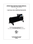
OPERATING INSTRUCTIONS MANUAL
(Please retain for future reference)
For
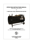
FRHR-100N/P RADIANT CONSTRUCTION HEATERS
CERTIFIED FOR USE IN CANADA AND U.S.A.
As per Standard ANSI Z83.7 2000/
CSA 2.14 2000 Gas Fired Construction Heaters Unvented /Unattended Type.
FLAGRO INDUSTRIES LIMITED
ST. CATHARINES, ONTARIO
CANADA
GENERAL HAZARD WARNING:
FAILURE TO COMPLY WITH THE PRECAUTIONS AND INSTRUCTIONS
PROVIDED WITH THIS HEATER, CAN RESULT IN DEATH, SERIOUS BODILY
INJURY AND PROPERTY LOSS OR DAMAGE FROM HAZARDS OF FIRE,
EXPLOSION, BURN, ASPHYXIATION, CARBON MONOXIDE POISONING, AND/OR
ELECTRICAL SHOCK.
ONLY PERSONS WHO CAN UNDERSTAND AND FOLLOW THE INSTRUCTIONS
SHOULD USE OR SERVICE THIS HEATER.
IF YOU NEED ASSISTANCE OR HEATER INFORMATION SUCH AS AN
INSTRUCTIONS MANUAL, LABELS, ETC. CONTACT THE MANUFACTURER.
WARNING:
FIRE, BURN, INHALATION, AND EXPLOSION HAZARD.
KEEP SOLID
COMBUSTIBLES, SUCH AS BUILDING MATERIALS, PAPER OR CARDBOARD, A
SAFE DISTANCE AWAY FROM THE HEATER AS RECOMMENDED BY THE
INSTRUCTIONS. NEVER USE THE HEATER IN SPACES WHICH DO OR MAY
CONTAIN VOLATILE OR AIRBORNE COMBUSTIBLES, OR PRODUCTS SUCH AS
GASOLINE, SOLVENTS, PAINT THINNER, DUST PARTICLES OR UNKNOWN
CHEMICALS.
WARNING:
NOT FOR HOME OR RECREATIONAL VEHICLE USE.
This heater is designed and approved for use as a
construction heater under ANSI Z83.7 2000 and
CSA 2.14 2000 Gas Fired Construction Heaters
We cannot anticipate every use which may be made
of our heaters. CHECK WITH YOU LOCAL FIRE
SAFETY AUTHORITY IF YOU HAVE QUESTIONS
ABOUT APPLICATIONS.
Other standards govern the use of fuel gases and heat
producing products in specific applications. Your local
authority can advise you about these.
-2-
WARNING:
INTENDED USE IS PRIMARILY THE TEMPORARY HEATING OF BUILDINGS
UNDER CONSTRUCTION, ALTERATION, REPAIR OR EMERGENCIES ONLY.
ALWAYS PROVIDE ADEQUATE VENTILATION. 1 SQ. IN. OF FRESH AIR MUST
BE SUPPLIED FOR EVERY 1000 BTUH OF HEAT.
THIS HEATER SHALL BE INSTALLED SUCH THAT IT IS NOT DIRECTLY
EXPOSED TO WATER SPRAY, RAIN AND/OR DRIPPING WATER.
MINIMUM CLEARANCE TO COMBUSTIBLES
TOP:
48 inches
SIDES:
30 inches
BOTTOM:
0 inches
INLET PRESSURES
FRHR-100N
FRHR-100P/PQD
Natural gas
Propane
MINIMUM Supply Pressure
7" W.C.
MAXIMUM Supply Pressure
14" W.C.
MINIMUM Supply Pressure
11" W.C.
MAXIMUM Supply Pressure
14" W.C.
MAINTENANCE
1.
This construction heater should be inspected before each use. All burner ports should remain clear and the
valve should be inspected for any possible damage. The heater should be test fired before each use. High
pressure air may be used to blow out the inside of the burner.
2.
The heater should be inspected annually by a qualified service person.
3.
The heater must be kept clear and free from combustible materials, gasoline and other flammable vapors
and liquids.
4.
The hose assembly shall be visually inspected prior to each use of the heater. If it is evident there is
excessive abrasion or wear, or the hose is cut, it must be replaced prior to the heater being put into
operation. The replacement hose assembly shall be supplied by Flagro Industries Limited. Please see Parts
List.
-3-
INSTALLATION
All natural gas heaters must be installed by a qualified gas fitter and must conform to local installation codes or, in
the absence of local codes, with the National Fuel Gas Code ANSI Z223.1/NFPA 54 and the Natural Gas and
Propane Installation Code, CSA B149.1. The natural gas heater is provided with a ½" male quick disconnect fitting.
The hose assembly used to install this heater must be a Type 1 CGA/AGA approved hose assembly equipped with a
½" female quick disconnect socket to mate with the inlet fitting. Before lighting the heater, all connections must be
leak checked using a soap and water solution. The heater must be installed on a level surface.
FOR A HEATER CONNECTION TO AN LP-GAS SUPPLY CYLINDER
1.
The installation must conform with local codes or, in the absence of local codes, with the Standard for the
Storage and Handling of Liquefied Petroleum Gases, ANSI/NFPA 58 and the Natural Gas and Propane
Installation Code, CSA B149.1.
2.
The hose assembly used to install this heater must be a Type 1 CGA/AGA approved hose assembly. The
heater must be located at least 20-ft (6.10m) from any LP-gas cylinder.
3.
The heater should be installed using a LP-gas cylinder with a minimum capacity of 30-lbs up to a
maximum capacity of 100-lbs.
4.
The cylinders used to supply this heater must provide for vapor withdrawal only.
5.
The heater must be connected with a “low pressure” regulator and POL inlet fitting. The POL fitting is
connected to the LP-gas cylinder by turning the POL nut counter clockwise and tightened using a wrench.
All connections must be checked for leaks using a soap and water solution or approved leak detector
solution. Use a wrench and turn the POL nut clockwise to disconnect the heater from the cylinder.
6.
The cylinder must be disconnected from the heater when not in use.
7.
The heater is to be stored indoors, the connection between the LP-gas supply cylinder(s) and the heater
must be disconnected and the cylinder(s) removed from the heater and stored in accordance with Chapter 5
of the Standard for the Storage and Handling of Liquefied Petroleum Gases, ANSI/NFPA 58 and CSA
B149.1, Natural Gas and Propane Installation Code.
-4-
LIGHTING INSTRUCTIONS
1.
Ensure the heater is connected to the proper source of gas and proper
inlet pressures are supplied. The heater must be installed by a
qualified installer.
2.
Set thermostat knob (green button) to high position. Rotate the control
knob (black) counter clockwise to 'PILOT' position. Depress and hold
control knob.
3.
Light the pilot burner using a long reach lighter through lighting hole
provided.
Release the knob after 60 seconds. Pilot will remain lit. Main burner
will remain off.
4.
Turn control knob counterclockwise to 'ON' position. Main burner
will light.
5.
If the main burner fails to light, turn the control knob clockwise to the
'OFF' position, wait 5 minutes and repeat step 3.
6.
The green knob controls the thermostat option. This will light and
extinguish the main burner as the temperature fluctuates.
SHUT OFF INSTRUCTIONS
1.
2.
Turn the control knob clockwise to the 'OFF' position. Both main
burner and pilot burners will extinguish.
Turn off source of fuel.
-5-
IMPORTANT NOTES FOR SUCCESSFUL LIGHTING AND OPERATIONAL SAFETY
1.
2.
For safety purposes, this heater model is equipped with a “tip over switch” which will prevent the heater from
operating or being lit if it is bumped, jarred, knocked over or positioned on an angle. In order to light and
operate properly, this heater MUST be placed on a flat horizontal surface in an upright position.
9
8
CORRECT POSITION
INCORRECT POSITION
The tip over switch is interlocked with the
thermocouple.
The connections on the
thermocouple block must be kept clean and tight at
all times to ensure proper operation of these
components.
Thermocouple block
Tip over switch
3.
While the heater unit does not require a filter, the unit must be kept clean and
the burner and pilot assembly must be kept free of dust and dirt to ensure
optimal and safe operation at all times
Store the unit in a clean environment and make sure that the unit is leak
checked and cleaned before every use. Do not clean the unit with volatile
substances. (see maintenance on Page 3)
-6-
PARTS LIST 2009/2010
FRHR-100N/P RADIANT CONSTRUCTION HEATERS
PART #
DESCRIPTION
FRHP-01NG
Gas Control Valve c/w thermostat – NG
FRHP-01LP
Gas Control Valve c/w thermostat – LP
FRHP-02NG
Pilot Assembly – NG
FRHP-02LP
Pilot Assembly – LP
FRHP-03
Pilot Line
FRHP-04
Thermocouple
FRHP-04A
Cut-off Switch
T-18
18” Thermocouple
FRHP-05RLP
Burner Orifice LP
FRHP05RNG
Burner Orifice NG
FRHP-07RLP
Burner Assembly – LP
FRHP07RNG
Burner Assembly – NG
FRHP-08R
Stainless Emitter Grid c/w shield and feet
FRHP-09
Tip-over Switch c/w wire
FRHP-10
⅜" Low Pressure Fire Line c/w Flare Nuts
FRHP-11
Reducing Nipple ½" x ⅜"
FRHP-12
Safety Screen Assembly (Two required)
FRHP-13A
Single Stage Regulator-LP c/w POL
FRHP-15
NG Regulator (used with WR Control)
FRHP-18
Thermo Bulb Bracket c/w Grommets
FRHP-21
1/4" Compression Nut & Sleeve for Pilot
Line
FRHP-22
1/4" Extended breakaway for Pilot Line
FRHP-50
Conversion Kit for FRHR NG TO LP
FRHP-51
Conversion Kit for FRHR LP TO NG
100-006
⅜" Quick disconnect socket – Female Socket
100-506
⅜" Quick disconnect plug – Male Socket
100-008
½" Quick Disconnect – Female Socket
100-508
½" Quick Disconnect – Male Socket
100-010
¾" Quick Disconnect – Female Socket
100-510
¾" Quick Disconnect – Male Plug
2009-1
-7-
FRHR-100 Parts List
1
2
FRHR-100 Parts List
6
3
7
4
5
6
8, 9, 10
FRHR-100 Parts List
11, 12
13
15
14
FRHR-100 Parts List
16, 17
11, 12
19, 20
18
FRHR-100 Parts List
Accessories
HOSES
Item #
Description
1
2
3
4
5
6
7
8
9
10
11
12
13
14
15
16
17
18
19
20
21
22
23
24
25
26
27
28
Removable Screen Assy
SS Emitter Grid Assy
3/8" Low Pressure Line
3/8" Flare x 3/8" MP Elbow
Gas Control Valve
Green Control Knob/Black Knob
Pilot Line
Propane QD Model
Natural Gas QD Model
Propane SAE Model
Propane Burner Assy
Natural Gas Burner Assy
Burner Fitting
Tipover Switch
ECO Cutoff Switch
Main Burner Orifice-NG
Main Burner Orifice-LP
Thermocouple
Pilot Assembly- LP
Pilot Assembly- NG
50 FT Propane Hose
50 FT NG Hose
Union Gas Single Manifold
Union Gas Douible Manifold
Enbridge Manifold
Enbridge Double Manifold
Enbridge Nipple
Enbridge Meter Key
P/N
FRHP-12
FRHP-08R
FHRP-10
49-6C
FRHP-01 LP/NG
FRHP-23/FRHP-19
FRHP-03A
122-CD/100-506
122-DC/100-506
48-6C
FRHP-07RLP
FRHP-07RNG
46-6C
FRHP-09
FRHP-04A
FRHP-05RNG
FRHP-05RLP
T-18
FRHP-02LP
FRHP-02NG
FRHP-101600LP
FRHP-101
MAN-U1
MAN-U2
MAN-E1
MAN-E2
MAN-NP
MAN-Key
21
22
MANIFOLDS
23
25
24 Not shown
26 Not shown
METER
27
28