1
OPERATING INSTRUCTIONS MANUAL
(Please retain for future reference)
For
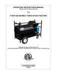
FVN/P-750 INDIRECT FIRED SPACE HEATERS
FOR OUTDOOR AND INDOOR INSTALLATIONS
CERTIFIED FOR USE IN CANADA AND U.S.A.
As per Standard ANSI Z83.7/CSA 2.14 2011 Gas Fired Construction Heaters / Unattended Type.
Issue date July 1, 2012
FLAGRO INDUSTRIES LIMITED
ST. CATHARINES, ONTARIO
CANADA
GENERAL HAZARD WARNING:
FAILURE TO COMPLY WITH THE PRECAUTIONS AND INSTRUCTIONS PROVIDED
WITH THIS HEATER, CAN RESULT IN DEATH, SERIOUS BODILY INJURY AND
PROPERTY LOSS OR DAMAGE FROM HAZARDS OF FIRE, EXPLOSION, BURN,
ASPHYXIATION, CARBON MONOXIDE POISONING, AND/OR ELECTRICAL
SHOCK.
ONLY PERSONS WHO CAN UNDERSTAND AND FOLLOW THE INSTRUCTIONS
SHOULD USE OR SERVICE THIS HEATER.
IF YOU NEED ASSISTANCE OR HEATER INFORMATION SUCH AS AN
INSTRUCTIONS MANUAL, LABELS, ETC. CONTACT THE MANUFACTURER.
WARNING:
FIRE, BURN, INHALATION, AND EXPLOSION HAZARD.
KEEP SOLID
COMBUSTIBLES, SUCH AS BUILDING MATERIALS, PAPER OR CARDBOARD, A
SAFE DISTANCE AWAY FROM THE HEATER AS RECOMMENDED BY THE
INSTRUCTIONS. NEVER USE THE HEATER IN SPACES WHICH DO OR MAY
CONTAIN VOLATILE OR AIRBORNE COMBUSTIBLES, OR PRODUCTS SUCH AS
GASOLINE, SOLVENTS, PAINT THINNER, DUST PARTICLES OR UNKNOWN
CHEMICALS.
WARNING:
NOT FOR HOME OR RECREATIONAL VEHICLE USE.
WARNING:
INTENDED USE IS PRIMARILY THE TEMPORARY HEATING OF BUILDINGS
UNDER CONSTRUCTION, ALTERATION, REPAIR OR EMERGENCIES ONLY.
-2-
This heater is designed and approved for use as a
construction heater under Standard ANSI Z83.7/
CGA 2.14. 2011.
We cannot anticipate every use which may be made
of our heaters. CHECK WITH YOU LOCAL FIRE
SAFETY AUTHORITY IF YOU HAVE QUESTIONS
ABOUT APPLICATIONS.
Other standards govern the use of fuel gases and heat
producing products in specific applications. Your local
authority can advise you about these.
SPECIFICATIONS
Model …………………………………………………….….
FVP-750 Propane
FVN-750 Natural Gas
Input …………………………………………………….…...
750,000 btuh
Fuel ………………………………………………………….
FVP-750 Propane
FVN-750 Natural Gas
Manifold Pressure ………………………………………….
1.50” W.C. Propane
2.20” W.C. NG
Maximum Inlet Pressure …………………………………
14.0” W.C. Propane
14.0” W.C. NG
Ignition ………………………………………………………
Direct Spark Ignition
…….……………………………………………...…
Thermostat Control
Air Circulation ……………………………………………….
7000 cfm
Fuel Consumption ……………………………………….....
37 lbs/hr Propane
806 cfh NG
Approved ………………………………………………….....
-3-
cETLus listed
INSTALLATION:
The installation of this heater for use with natural gas shall conform with local
codes or, in the absence of codes, with the National Fuel Gas Code ANSI
Z233.1/NFPA 54 and the Natural Gas and Propane Installation Code, CSA
B149.1. This heater must be installed by a qualified gas technician, following
local codes published by the authority having jurisdiction. All installations
performed in the state of Massachusetts must be completed by a qualified
plumber and gas fitter of the State of Massachusetts.
The installation of this heater for use with propane tank or cylinder shall conform
with Local codes or, in the absence of local codes, with the Standard for the
Storage and Handling of Liquefied Petroleum Gases, ANSI / NFPA 58 and the
Natural Gas and Propane Installation Code, CSA B149.1.
This heater must be located at least 10ft (3m) from any propane gas cylinder.
This heater shall not be directed toward any propane gas container within 20ft
(6m).
CLEARANCE TO COMBUSTIBLES:
TOP
FRONT
SIDES
REAR
FLUE PIPE
1 ft
1 ft
1 ft
2 ft
2 ft
CONNECTING THE CYLINDER (LP Models only):
The heater must be located at least 6ft (1.83m) in the U.S.; or 10ft (3m) in
Canada, from any propane gas container
If cylinders are used to supply the heater, no cylinders smaller than 100lb
capacity shall be used. These cylinders must supply a vapor withdrawal only.
1.
All cylinder connections must be made using a wrench to tighten the POL
fitting.
2.
Be sure that the cylinder valve is in the closed position when connection or
disconnecting the cylinder.
3.
A soap and water solution must be applied to all connections in order to
leak check the system.
-4-
The gas must be turned off at the propane supply cylinder(s) when the heater is
not in use. When the heater is to be stored indoors, the connection between the
propane supply cylinder(s) and the heater must be disconnected and the
cylinders removed from the heater and stored in accordance with Standard for
the Storage and Handling or Liquefied Petroleum Gases, ANSI/NFPA 58 and
CSA B149.1, Natural Gas and Propane Installation Code.
PIPING:
This heater must be installed by a qualified gas technician following
local codes published by the authority having jurisdiction. Sizing of
supply piping must be determined using the length of pipe run as
well as total btuh rating of the appliance(s). Appropriate piping
tables must be used to determine size of supply piping dependant
on the length of run from source.
PRESSURES:
MAXIMUM INLET PRESSURES:
LP:
NG:
14.0 IN. WC.
14.0 IN. WC.
MINIMUM INLET PRESSURES:
LP:
NG:
8.0 IN. WC.
7.0 IN. WC.
This heater must be supplied by pressures indicated on the
approval label. Over pressure may cause controls to fail.
DO NOT supply this heater with more than ½ psig
(14.0 in. W.C.)
Note: A second stage regulator must be installed if the
supply pressure exceeds ½ psig.
FUEL:
This heater will operate on propane OR natural gas. The
fuel selector valve must be in the correct position (LP or NG)
before operating. The manifold pressures are listed on the
approval label. To determine which fuel to use see rating
plate. DO NOT attempt to use the heater without consulting
the rating plate.
HOSES:
All hoses used to connect this heater of fuel supply must be
Type 1 approved propane / natural gas hose assemblies.
-5-
ELECTRICAL:
This appliance is equipped with a grounded receptacle for your protection against
shock hazard and should be plugged directly into a properly grounded plug. The
electrical grounding of the heater shall be in compliance with the National
Electrical Code, ANSI/NFPA 70, or CSA C22.1, Canadian Electrical Code, Part I.
THIS APPLIANCE IS ABLE TO RECEIVE 1 PHASE OR 3 PHASE POWER.
208V-230V SUPPLY MUST BE AVAILABLE.
POWER SUPPLY:
SINGLE PHASE: 208V-230V, 30AMP BREAKER OR 30 AMP TIME DELAY
FUSE, 8/3 AWG AT 100FT MAX.
OR
THREE PHASE: 208V-230V, 25AMP BREAKER OR 25AMP TIME DELAY
FUSE, 10/4 AWG AT 100FT MAX.
**POWER CORD PLUG ENDS PROVIDED WITH UNIT FOR 1 PHASE OR 3
PHASE OPERATION
This heater is equipped with a VFD “Variable Frequency Drive” to control the
primary fan acceleration & de-acceleration. The VFD has been password
protected to prevent improper use. If access to VFD controls is required for
troubleshooting, please contact manufacture for assistance.
FLUE PIPE:
For outdoor applications the flue pipe connection must
terminate with a vertical run of at least 2ft complete with rain
cap.
For indoor installations the venting must consist of a
minimum 2ft vertical run to a maximum of 20ft total vent
length. See diagram below for horizontal vent installation.
The vent outlet on the heater is 8” diameter. Certified venting
must be used at all times. Vent cap must be installed in
situations where downdrafts occur.
All venting must
correspond with the CSA B149 standard or in its absence,
local codes.
-6-
FLUE TERMINATIONS
C
B
90 DEG ELBOW
45 DEG ELBOW
A
EXTERIOR WALL
FLUE OUTLET OF HEATER
A - Vertical vent run must be a minimum of 2ft from heater outlet.
B - Maximum horizontal run is 20ft
Note: 90deg Elbow = 5ft
C - Vent termination in horizontal position must be minimum 2ft from wall.
A 45deg elbow is recommended at horizontal termination.
Note: Horizontal flue run - Rise ratio 1:10.
DUCTING:
Heater duct with a minimum temperature rating of 300 deg F
including wire reinforcement to prevent collapsing must be
used. Heater is designed for use with 2 x 16” diameter ducts
equipped with gear clamp (FV-HD16X25B).
Install ducting to the outlet of the heater using gear clamp
provided on the collar of the ducting. Ducting should be
inspected periodically for tearing and/or wear marks. Ducting
should be stored in a dry area when not in use
-7-
MAINTENANCE:
1. Every construction heater should be inspected before each use, and at
least annually by a qualified service person. Incorrect maintenance my
result in improper operation of the heater and serious injury could
occur.
2. Service and maintenance should only be done by a qualified service person.
The hose assemblies shall be visually inspected prior to each use of the
heater. If it is evident there is excessive abrasion or wear, or the hose is cut,
it must be replaced prior to the heater being put into operation. The
replacement hose assembly shall be that specified by the manufacturer.
3. The appliance must be kept clear and free from combustible materials,
gasoline and other flammable vapors and liquids.
4. The flow of combustion and ventilation air must not be obstructed. Be sure to
check the fan assembly and ensure that the motor and blade are operating
properly.
5. Compressed air should be used to keep components free of dust and dirt
build up. Note: Do not use the compressed air inside any piping or regulator
components.
6. High Limit Switches (Part# FV-706 and FV-707) should be checked each
season. These limit switches will ensure the burner shuts down if the
temperature exceeds 200°F degrees at rear of unit and 250°F at the outlet.
7. Heat Exchanger should be cleaned if smokey conditions continue even after
the air adjustments on the burner are made.
START UP INSTRUCTIONS:
1.
Position heater properly & on a level surface before operating
2.
Connect gas supply to heater (leak test all connections)
3.
Ensure the (Thermostat / Manual) selector switch is in the “OFF”
position
4.
Attach power supply, 208-230V/ 1-Phase or 208-230V/ 3-Phase to
proper receptacle.
-8-
5.
Turn disconnect switch (single or three phase) depending on power
supply to “ON” position
6.
Move fuel selector valve to correct position – LP or NG
7.
Move switch to “MANUAL” position for manual control.
“OR”
8.
Move switch to “THERMOSTAT” position for thermostatic control.
Please Note:
1. If using Thermostat kit, the heater must be started in Thermostat position.
2. When changing between manual and thermostat operation, the heater
must be left in the “OFF” position until blower fan completely shuts down
before changing position to prevent the burner from locking out.
3. When using a generator for electrical supply, make sure the generator is
properly grounded and is at a 60Hz frequency.
4. In the event that a generator is being used and runs out of fuel, make sure
the heater switch is in the “OFF” position before restarting generator,
failure to do so may damage heater.
TO SHUT DOWN:
1.
Close main gas supply valve.
2.
Move Thermostat/Manual switch to “OFF” position.
3.
Waiting until blower fan shuts down (3 minutes approx.)
4.
Move Disconnect switch (single phase or three phase) depending on
power supply to “OFF” position.
5.
Turn main breaker to “OFF” position
6.
Disconnect heater from gas supply.
-9-
IF HEATER FAILS TO START:
1.
Press manual reset button at rear of burner.
2.
Check gas pressure supply. Supply and manifold pressure must
follow those on rating plate.
3.
Ensure proper power supply is being used.
4.
If heater fails to ignite after 3 attempts, call your supplier for service.
SAFE OPERATION PRECAUTIONS:
1.
For use with propane or natural gas only. Fuel sector valve must be in
correct position. See approval label.
2.
Use Thermostat/Manual switch to shut down the heater. Do not try to
shut down the heater by the disconnect switches or unplugging the
electrical cord.
3.
Do not plug anything other than the thermostat into the “Thermostat”
plug.
4.
Follow electrical requirements shown on rating plate and/or Electrical
requirements section of this manual.
5.
Before removing any guards or performing any maintenance, be sure
that the main power supply is disconnected.
6.
The hose assembly shall be protected from traffic, building material &
contact with hot surfaces, both during use & while in storage
- 10 -
COMBUSTION AIR ADJUSTMENTS:
NOTE:
Proper combustion air adjustment must be achieved using a
certified combustion analyzer to ensure complete combustion.
The air adjustment should be made to achieve 10% CO2 on natural
gas and 12% CO2 on propane.
SETTING THE AIR ADJUSTMENT PLATE
A) Regulation of the combustion air flow is made by adjustment of the manual
AIR ADJUSTMENT PLATE (1) after loosening the FIXING SCREWS (2 and
3). The initial setting of the air adjustment plate should be made according to
Column 3 in the Burner Set-up Chart.
B) The proper number on the manual AIR
ADJUSTMENT PLATE (1) should line up
with the SETTING INDICATOR (4) on the
fan housing cover. Once set, the air adjustment plate should be secured in place
by tightening SCREWS 2 and 3.
C) The final position of the air adjustment
plate will vary on each installation. Use instruments to establish the proper settings
for maximum CO2.
NOTE: Variations in flue gas, CO2 and temperature readings may be
experienced when the burner cover is put in place. Therefore, the burner cover
must be in place when making the final combustion instrument readings, to
ensure proper test results.
- 11 -
BURNER SET-UP CHART
1
2
3
FIRING RATE
(BTUH)
HEAD
SETTING
AIR DAMPER
SETTING
750,000
4.0
4.5
***Please Note: FVN/P-750 is not equipped with the “servomotor”.
BURNER DIMENSIONS
- 12 -
ELECTRODE AND FLAME PROBE ADJUSTMENTS
IMPORTANT:
Do not turn the ignition electrode. Leave it as shown in the
drawing. If the ignition electrode is put near the ionization
probe, the amplifier of the control box may be damaged.
- 13 -
- 14 -
***Please note: FVN/P-750 is a single stage burner only.
- 15 -