1
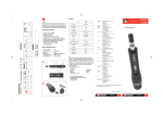
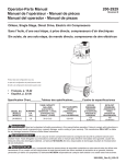
IS-1580-TL-98
HAYWARD HIGH-PERFORMANCE PUMPS
INSTALLATION AND OPERATING INSTRUCTIONS
IMPORTANT SAFETY INSTRUCTIONS
When installing and using this electrical equipment, basic safety precautions should always be followed,
including the following: Failure to follow instructions may result in injury.
READ AND FOLLOW ALL INSTRUCTIONS
1. WARNING - To reduce risk of injury, do not permit children to use this product unless they are closely supervised at all times.
2. CAUTION - This pump is U.L. listed for permanently installed pools and may also be used with hot tubs and spas if so marked.
It is not U.L. listed for storable pools. A permanently installed pool is constructed in or on the ground and cannot be readily
disassembled for storage. A storable pool is constructed so that it may be readily disassembled for storage and reassembled to
its original integrity.
3. If installed within an outer enclosure or beneath the skirt of a hot tub or spa, adequate ventilation and free circulation of air must
be provided to prevent overheating of the motor.
4. Use motor bonding lug to connect the motor with other bonding parts using a #8 AWG conductor as required by electrical codes.
NOTE: If your pump is equipped with a 3 ft. (1 m) cord and twist lock plug, items 5 through 8 apply.
5. WARNING - Risk of Electric Shock. Connect only to a grounding-type receptacle protected by a ground fault circuit interrupter
(GFCI). Contact a qualified electrician if you cannot verify that the receptacle is protected by a GFCI.
6. Do not bury cord. Locate cord to minimize abuse from lawn mowers, hedge trimmers, and other equipment.
7. WARNING - To reduce the risk of electric shock, replace damaged cord immediately.
8. WARNING - To reduce the risk of electric shock, do not use extension cord to connect unit to electric supply; provide a properly
located outlet.
SAVE THESE INSTRUCTIONS
GENERAL TIPS ON PUMP INSTALLATION
STARTING AND PRIMING INSTRUCTIONS
For best pump performance, locate the system below the
pool water line and as close to the pool as practical. If
you own an above-ground pool, please see Note: NSPI-4
Article V, for safe and proper installation of the equipment
package. Make sure suction joints are tight. Suction pipe
should be as large or larger than discharge pipe.
Fill strainer housing with water to suction pipe level.
Never operate the pump without water. Water acts as a
coolant and lubricant for the mechanical shaft seal.
Damp, non-ventilated locations should be avoided.
Motors require free circulation of air to aid in cooling.
CAUTION: All suction and discharge valves must be
open when starting the system. Failure to do so could
result in severe personal injury and/or property
damage.
Insure that the electrical supply available agrees with the
motor’s voltage, phase and cycle, and that wire size is
adequate for the HP (KW) rating and distance from power
source. Motor must always be properly grounded. If cord
connected, use only a properly grounded outlet. Electrical
circuits must be protected by proper size ground fault
circuit interrupter (GFCI) as required by applicable
electrical codes. All electrical wiring must be performed
by qualified personnel, and must conform to local codes
and regulations.
Open all suction and discharge lines and valves, as well
as air bleed (if available) on filter. (The air that is to be
displaced from the suction line must have some place to
go.)
Turn on power and allow a reasonable time for priming.
Priming time depends on suction lift and horizontal length
of suction piping. If the pump will not start, or will not
prime, see TROUBLE SHOOTING GUIDE on back page.
NOTE: NSPI-4 Article V, standard for above-ground and
on-ground pools, advises that components such as the
filtration system, pumps and heater be positioned so as to
prevent their being used as a means of access to the pool
by young children.
PART NUMBER
DWG.
NO.
DESCRIPTION
NO.
REQ’D.
MODEL
SP-1575LXTL
MODEL
SP-1580TL
MODEL
SP-1580X15TL
1
Bolt, No. 10-24 Hex. Head
8
SPX1500-N2
SPX1500-N2
SPX1500-N2
2
Housing Cover
1
SPX1580-BP
SPX1580-BP
SPX1580-BP
3
Housing O-Ring
1
SPX1580-Z-1
SPX1580-Z-1
SPX1580-Z-1
4
Impeller
1
SPX1500-F
SPX1500-L
SPX1500-L
5
Seal Assembly
1
SPX1250-XZ-2
SPX1250-XZ-2
SPX1250-XZ-2
6
Pump Housing
1
SPX1580-AAP
SPX1580-AAP
SPX1580-AAP
7
Nut, No. 10-24 Hex.
8
SPX1500-Y-2
SPX1500-Y-2
SPX1500-Y-2
8
Motor-to-Housing Bolt
4
9
Motor
1
SPX1510-Z-1E
SPX1510-Z-1XE
SPX1515-Z-1E
10
Strainer Housing
1
SP-1500-CP
SP-1500-CP
SP-1500-CP
11
O-Ring
1
SPX1500-W
SPX1500-W
SPX1500-W
12
Check Valve Assembly (Optional)
1
SPX1500-RA
SPX1500-RA
SPX1500-RA
SPX1500-LX
To order, specify motor manufacturer, HP and pump model no.
13
Basket
1
SPX1500-LX
SPX1500-LX
14
Strainer Cover O-Ring
1
SPX1500-P
SPX1500-P
SPX1500-P
15
Strainer Cover, Clear Lexan
1
SPX1500-D-2
SPX1500-D-2
SPX1500-D-2
16
Drain Plug (Optional - special models)
2
SPX1700-FG
SPX1700-FG
SPX1700-FG
SPX1500-X1
SPX1550-WA-1
©
---
Strainer Shim Ring (Horizontal Outlet Pumps Only)
1
SPX1500-X1
SPX1500-X1
---
Twist Lock Cord Set
1
SPX1550-WA-1
SPX1550-WA-1
SEAL CHANGE INSTRUCTIONS
Power Flo™ LX Series with Twist Lock Cord
GENERAL
Exercise extreme care in handling and installing the new seal and ceramic seat assembly.
The lapped and polished surfaces may easily be damaged by dirt or scratching.
For safety, all service must be performed with all power shut off.
1. Remove pump and motor assembly from piping
system.
2. Remove pump housing cover (with strainer
attached) by removing the eight (8) housing bolts
and nuts which fasten housing cover to pump
housing. The impeller is now exposed.
3. To remove impeller, insert screwdriver in slot at
end of motor.* Hold screwdriver so as to keep
shaft from turning, and rotate the impeller in a
counterclockwise direction. The spring portion of
the seal assembly is now exposed.
4. Note carefully the position of the spring seal and
pull it off the impeller.
5. To remove the stationary (ceramic seat) part of
the seal assembly:
a. Loosen the four (4) motor securing bolts and
disengage the motor from the pump housing.
b. With motor removed, press the clear plastic
and ceramic seat assembly out of the pump
housing recess. If tight, tap lightly from the
“motor” side.
6. Clean and lubricate the impeller hub shaft and
pump housing seal recess with a dilute solution
of non-granulated liquid-type soap. The use of
petroleum or silicone lubricants can contribute to
seal leakage.
7. Press the new spring portion of the assembly
onto the impeller, black polished surface facing
away from the impeller.
8. Carefully press ceramic seat, with O-ring, into
clear plastic seat retainer—polished surface
facing out. Be sure O-ring is in place on cut ridge
of clear plastic retainer. Press plastic retainer,
with ceramic seat inside, into recess of pump
housing—O-ring end first. Replace the assembly
firmly and evenly.
9. Carefully insert the motor shaft through the seat
assembly, and secure motor to pump housing
with four (4) motor securing bolts. (Be sure motor
base is positioned properly.)
10. Screw the impeller, with spring seal, onto the
motor shaft, hand tight, by turning clockwise.
11. Clean fiber gasket (replace if necessary) and
fasten housing cover to pump housing with
eight (8) bolts and nuts. Tighten bolts and nuts
alternately and evenly.
12. Reconnect pump to piping system. Be sure to fill
strainer with water before restarting.
* For A.O. Smith Canopy Style Motors: Remove motor end cover and carefully apply wrench to flat on motor shaft to hold shaft from turning.
ELECTRICAL GUIDE — 60 CYCLE MOTORS — SINGLE PHASE
MOTOR
VOLTS
CIRCUIT BREAKER
RATINGS - AMPS
BRANCH FUSETRON
RATINGS - AMPS
KW
HP
.55
3/4
115
15
15
RECOMMENDED
WIRE SIZE
0-50’
#14
.75
1
115
20
20
#12
1.1
1-1/2
115
20
20
#12
A separate electrical circuit, utilizing a rating as above, is recommended.
TROUBLE SHOOTING GUIDE
A. MOTOR WON’T START
1. Check for improper or loose connections, open switches
or relays, blown circuit breakers or fuses.
2. Manually check rotation of motor shaft for free
movement and lack of obstruction.
B. MOTOR CUTS OUT — Check for:
1. Wiring, loose connections, etc.
2. Low voltage at motor (frequently caused by
undersized wiring).
3. Binding and overload. (Amperage reading)
a. If pump develops a vacuum, check for blocked suction
line or strainer, or air leak in suction piping.
b. If pump does not develop a vacuum and pump has
sufficient “priming water”:
1. Tighten all bolts and fittings.
2. Check voltage to make sure pump is up
to speed.
3. Open pump and check for clogging or
obstruction.
4. Remove and replace shaft seal.
E. LOW FLOW — Generally, check for:
NOTE: Your Hayward pump motor is equipped with
Automatic Thermal Overload Protection. The
motor will automatically shut off, under normal
conditions, before heat damage build-up, due to
an improper operating condition, can occur. The
motor will auto-restart when safer heat level is
reached.
C. MOTOR HUMS, BUT DOES NOT START—Check for:
1. Centrifugal switch stuck in open position.
2. Binding of motor shaft.
D. PUMP WON’T PRIME
1. Make sure pump/strainer housing is filled with water and
that cover O-ring is clean and properly seated. Make
sure strainer cover is locked firmly in position.
2. Make sure all suction and discharge valves are open
and unobstructed, and that pool water level is above all
suction openings.
1. Clogged or restricted strainer or suction line;
undersized pool piping.
2. Plugged or restricted discharge line of filter
(high discharge gauge reading).
3. Air leak in suction (bubbles issuing from return fittings).
4. Pump operating underspeed (low voltage).
5. Plugged or restricted impeller.
F. NOISY PUMP — Check for:
1. Air leak in suction causing rumbling in pump.
2. Cavitation due to restricted or undersized suction line
and unrestricted discharge lines. Correct suction
condition or throttle discharge lines, if practical.
3. Vibration due to improper mounting, etc.
4. Foreign matter in pump housing.
5. Motor bearings made unserviceable by wear, rust, or
continual overheating.
3. Block off suction as close to pump as possible and
determine if pump will develop a vacuum.
MAINTENANCE
STORAGE/WINTERIZING
1. Clean strainer basket regularly. Do not strike basket
to clean. Inspect strainer cover gasket regularly and
replace as necessary.
Pump and motor must be protected from freezing. Shut off
all electric power. Disconnect cord/electrical connections
and plumbing connections. Drain thoroughly and clean out
any debris. Store pump and motor in a dry, well-ventilated
room.
2. Hayward pumps have self-lubricating motor bearings
and shaft seals. No lubrication is necessary.
3. Keep motor clean. Insure air vents are free from
obstruction.
4. Occasionally, shaft seals must be replaced, due to
wear or damage. See instructions.
SERVICE & REPAIRS
Consult your local authorized Hayward dealer or service center. No pumps or motors may be returned directly to the factory
without the expressed written authorization of Hayward Pool Products, Inc.
Rev: 8/98
© 1998 Hayward
Printed in U.S.A.