1
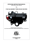
OPERATING INSTRUCTIONS MANUAL
(Please retain for future reference)
For
FVO-400 INDIRECT FIRED SPACE HEATERS
CERTIFIED FOR USE IN CANADA AND U.S.A.
As per CSA B140.8 Portable Oil Fired Heaters / CSA B140.02003 Oil Burning Equipment
Construction Heaters Unattended Type.
Issue date October 1, 2008
FLAGRO INDUSTRIES LIMITED
ST. CATHARINES, ONTARIO
CANADA
-1-
GENERAL HAZARD WARNING:
FAILURE TO COMPLY WITH THE PRECAUTIONS AND INSTRUCTIONS
PROVIDED WITH THIS HEATER, CAN RESULT IN DEATH, SERIOUS BODILY
INJURY AND PROPERTY LOSS OR DAMAGE FROM HAZARDS OF FIRE,
EXPLOSION, BURN, ASPHYXIATION, CARBON MONOXIDE POISONING,
AND/OR ELECTRICAL SHOCK.
ONLY PERSONS WHO CAN UNDERSTAND AND FOLLOW
INSTRUCTIONS SHOULD USE OR SERVICE THIS HEATER.
THE
IF YOU NEED ASSISTANCE OR HEATER INFORMATION SUCH AS AN
INSTRUCTIONS MANUAL, LABELS, ETC. CONTACT THE MANUFACTURER.
WARNING:
FIRE, BURN, INHALATION, AND EXPLOSION HAZARD.
KEEP SOLID
COMBUSTIBLES, SUCH AS BUILDING MATERIALS, PAPER OR
CARDBOARD, A SAFE DISTANCE AWAY FROM THE HEATER AS
RECOMMENDED BY THE INSTRUCTIONS. NEVER USE THE HEATER IN
SPACES WHICH DO OR MAY CONTAIN VOLATILE OR AIRBORNE
COMBUSTIBLES, OR PRODUCTS SUCH AS GASOLINE, SOLVENTS, PAINT
THINNER, DUST PARTICLES OR UNKNOWN CHEMICALS.
WARNING:
NOT FOR HOME OR RECREATIONAL VEHICLE USE.
WARNING:
INTENDED USE IS PRIMARILY THE TEMPORARY HEATING OF BUILDINGS
UNDER CONSTRUCTION, ALTERATION, REPAIR OR EMERGENCIES ONLY.
ALWAYS PROVIDE ADEQUATE VENTILATION. 1 SQ. IN. OF FRESH AIR
MUST BE SUPPLIED FOR EVERY 1000 BTUH OF HEAT.
THIS HEATER SHALL BE INSTALLED SUCH THAT IT IS NOT DIRECTLY
EXPOSED TO WATER SPRAY, AND/OR DRIPPING WATER.
-2-
This heater is designed and approved for use as a
construction heater under CSA B140.8 Portable Oil
Fired Heaters / CSA B140.02003 Oil Burning Equipment.
We cannot anticipate every use which may be made
of our heaters. CHECK WITH YOU LOCAL FIRE
SAFETY AUTHORITY IF YOU HAVE QUESTIONS
ABOUT APPLICATIONS.
Other standards govern the use of fuel gases and heat
producing products in specific applications. Your local
authority can advise you about these.
SPECIFICATIONS
Model …………………………………………………….….
FVO-400
Input …………………………………………………….…...
390,000 btuh
Fuel ………………………………………………………….
No.1, No. 2,
diesel or
kerosene
Fuel Pressure ……………………………………………....
170 psi
Nozzle ……………………………………………………….
(Delavan)
2.25 x 45B
Ignition ……………………………………………………….
Direct Spark
…….……………………………………………...….
Thermostat
Control
Air Circulation ……………………………………………….
2500 cfm
Fuel Consumption ………………………………………......
2.75 Gal/hr
Approved …………………………………………………......
cETLus listed
-3-
INSTALLATION:
The installation of this heater for use with No.1, No.2, Diesel or Kerosene and
shall conform with local codes or, in the absence of codes, with the National Fuel
Gas Code ANSI Z223.1/NFPA 54. Installation of the unit shall be in accordance
with the regulations of the authorities having jurisdiction or the CSA Standard
B139.
CLEARANCE TO COMBUSTIBLES:
TOP
FRONT
SIDES
REAR
FLUE PIPE
3 ft
10 ft
3 ft
3 ft
3 ft
FUEL:
ELECTRICAL:
This heater will operate with No.1, No.2, Diesel or Kerosene.
Note:
No.1 Fuel Oil or Kerosene must be used for
temperatures less than –10º C (8º F).
WARNING
Electrical Grounding Instructions
This appliance is equipped with a three-prong (grounding)
plug for your protection against shock hazard and should be
plugged directly into a properly grounded three-prong
receptacle.
115v supply must be available. Please note that the heater
requires 15 amps for proper operation. Ensure appropriate
gauge extension cord is used.
• 12/3 AWG at 50 Feet
• 10/3 AWG at 100 Feet
FLUE PIPE:
Flue pipe connection must terminate with a vertical run at
least 2ft long.
The vent outlet on the heater is 6” diameter. Certified venting
must be used at all times. Vent cap should be installed in
situations where downdrafts occur.
All venting must
correspond with the CSA B149 standard or in its absence,
local codes.
-4-
FV SERIES CONSTRUCTION HEATER – VENTING REQUIREMENTS
1. VERTICAL FLUE TERMINATIONS
B
A
VERTICAL FLUE RUN
D
HORIZONTAL FLUE RUN - RISE RATIO 1:10
FLUE OUTLET OF HEATER
2. HORIZONTAL FLUE TERMINATIONS
B
C
FLUE OUTLET OF HEATER
EXTERIOR WALL
A -
VENT TERMINATION MUST BE A MINIMUM OF 2FT HIGHER THAN ANY POINT
WITHIN 10FT.
B -
MAXIMUM HORIZONTAL RUN IS 30FT.
NOTE: 90deg ELBOW = 10ft HORIZONTAL VENT ALLOWANCE
45deg ELBOW = 5ft HORIZONTAL VENT ALLOWANCE
C -
VENT TERMINATION IN HORIZONTAL POSITION MUST BE MINIMUM 4ft FROM ANY
COMBUSTABLE SURFACE
D -
EXTERIOR VERTICAL VENT TERMINATION MUST BE A MINIMUM OF 2ft.
NOTE:
ALL VENT TERMINATIONS MUST HAVE A RAIN CAP INSTALLED AS PER
LOCAL CODE REQUIREMENTS.
-5-
DUCTING:
Canvas heater duct with a minimum temperature handling of
300 deg F. including wire reinforcement to prevent collapsing.
Heater is designed for use with 2 x 12” diameter ducts
equipped with pin lock couplings (FV-D12).
Install ducting to outlet on the heater using pin-locks provided
on collar of ducting. Ducting should be inspected periodically
for tearing and/or wear marks. Ducting should be stored in a
dry area when not in use
MAINTENANCE:
1. Every construction heater should be inspected before each use, and at
least annually by a qualified service person. Incorrect maintenance my
result in improper operation of the heater and serious injury could occur.
2. Service and Maintenance only to be performed by a qualified service person.
3. The hose assemblies shall be visually inspected prior to each use of the
heater. If it is evident there is excessive abrasion or wear, or the hose is cut, it
must be replaced prior to the heater being put into operation. The replacement
hose assembly shall be that specified by the manufacturer.
4. The flow of combustion and ventilation air must not be obstructed. Be sure to
check the fan assembly and ensure that the motor and blade are operating
properly.
5. Compressed air should be used to keep components free of dust and dirt build
up. Note: Do not use the compressed air inside any piping or regulator
components.
6. Change fuel filter insert (Part# FVO-418) once per month. Change fuel filter
cartridge (Part# FVO-419) once every 6 months.
7. Change oil nozzle (Part# FV-435) once per year.
8. Fan Limit Switch (Part# FV-407A) should be replaced if the fan motor does not
shut off after the heat exchanger has cooled down.
9. The High Limit Switches (Part# FV-406 & FV-437) should be checked each
season. These limit switches will ensure the burner shuts down if the
temperature exceeds 150º F at rear of unit and 290º F at the outlet.
10. Fuel tank should be drained on a regular basis by removing drain plug.
11. CAUTION – Do not have any source of ignition near the heater when draining
tank.
-6-
NOTE: No.1 fuel oil or kerosene is recommended for temperatures below
-10º C / 8º F
11. Heat Exchanger should be cleaned if smokey conditions continue even after
the air adjustments on the burner are made.
START UP INSTRUCTIONS:
1.
Be sure the switch in is the “OFF” position.
2.
Ensure electrical cord is grounded and heater is on a level surface.
3.
Plug in supply cord to 115V 15amp outlet.
4.
Move switch to “MANUAL” position for manual control.
5.
Move switch to “THERMOSTAT” position for thermostatic control.
Please Note:
1. If using Thermostat on unit, unit must be started in Thermostat position.
2 When changing between manual and thermostat operation, the heater
must be left in the “OFF” position for 30 seconds to prevent the burner from
locking out.
3. When using a generator for electrical supply, make sure the generator
is properly grounded and generator is at a 60Hz frequency.
4. In the event that a Generator is being used and the generator runs out of
fuel, make sure the heater switch is in the “OFF” position before restarting
generator, failure to do so may damage heater.
TO SHUT DOWN:
1.
Move switch to “OFF” position.
NOTE:
Fan will continue to operate after the burner shuts down. Once the
unit cools down, the fan will stop.
-7-
IF HEATER FAILS TO START:
1.
Press manual reset button at rear of burner.
2.
Check fuel level. There must be 2-4 gallons of fuel in the tank for the
heater to start properly.
3.
Make sure there are no air locks in fuel lines or filter.
4.
Ensure proper power supply and extension cord is being used.
5.
Check for dirty fuel filter or blocked fuel supply line.
6.
Check burner nozzle assembly.
NOTE: IF THE BURNER HAS BEEN RESET SEVERAL TIMES THERE
MAY BE AN ACCUMULATION OF OIL IN THE CHAMBER! DO NOT
CONTINUE TO TRY AND START THE HEATER!
DRAIN OIL FROM HEAT EXCHANGER USING DRAIN HOLE AT FRONT OF
HEAT EXCHANGER FOR 15-20 MINUTES BEFORE ATTEMPTING TO
RELIGHT. LET REMAINING EXCESS OIL BURN OFF BEFORE CHECKING
COMBUSTION OF UNIT.
SAFE OPERATION PRECAUTIONS:
1.
Do not fill fuel tank while heater is operation.
2.
Do not attempt to start heater if excess oil remains in the heat
exchanger.
3.
Use switch to shut down the heater. Do not try to shut down the heater
by unplugging the electrical cord.
4.
Do not plug anything other that the thermostat into the “Thermostat”
plug.
5.
Do not use any fuel other that those listed on rating plate.
6.
Follow electrical requirements shown on rating plate and/or Electrical
requirements section of this manual.
7.
Before removing any guards or performing any maintenance, be sure
that the main power supply is disconnected.
-8-
COMBUSTION AIR ADJUSTMENTS:
NOTE:
Proper combustion air adjustment must be achieved using a certified
combustion analyzer and smoke tester to ensure complete
combustion.
The air adjustment should be made to achieve 10% CO2 and No. 1 or “trace”
smoke. (Bacharach Scale)
SETTING THE AIR ADJUSTMENT PLATE
A)
Regulation
of
the
combustion air flow is made
by adjustment of the manual
AIR ADJUSTMENT PLATE
(1) after loosening the FIXING
SCREWS (2 & 3). The initial
setting of the air adjustment
plate
should
be
made
according to Column 5 in the
Burner Set-up Chart.
B) The proper number on the
manual AIR ADJUSTMENT
PLATE (1) should line up with
the SETTING INDICATOR (4)
on the fan housing cover.
Once set, the air adjustment
plate should be secured in
place by tightening SCREWS
2 and 3.
C) The final position of the air
adjustment plate will vary on each installation. Use instruments to establish the
proper settings for maximum CO2 and a smoke reading of zero.
NOTE: Variations in flue gas, smoke, CO2 and temperature readings may be
experienced when the burner cover is put in place. Therefore, the burner cover
must be in place when making the final combustion instrument readings, to
ensure proper test results.
-9-
BURNER SET-UP CHART
1
2
3
4
ACTUAL
FIRING RATE
± 5%
NOZZLE
SIZE
PUMP PRESSURE
TURBULATOR
SETTING
GPH
GPH
PSI
BAR
2.75
2.25 x 45°
150
10
5
5
AIR
DAMPER
SETTING
4-6
* Note – Air damper setting is typically set at 4 for operation in colder
temperatures. A combustion analyzer should always be used when setting the
the burner.
TEMPERATURE FEELER GAUGE ADJUSTMENT
(ATTACHED TO FAN SWITCH)
The temperature feeler gauge is required to be always touching the heater
exchanger.
The temperature feeler gauge controls the air flow over the fan switch, which
eliminates any unnecessary fan cycling. The temperature feeler gauge can be
adjusted for different outside temperatures, by rotating the location of the
temperature feeler gauge holes. This will provide maximum performance of the
unit in different applications.
If supply air is warm (-5º C, indoor application):
Turn the temperature feeler gauge so that the holes are parallel with the heat
exchanger. This will help the fan switch to remain cool and not overheat. See
following:
If supply air is cold (under -5ºC):
Turn the temperature feeler gauge so that the holes are closed off as the air goes
over the heat exchanger. This will reduce fan cycling and the unit from shutting
down. See following:
- 10 -
In extreme cold conditions, cover the holes on the temperature feeler gauge using
foil tape. Ensure that the temperature feeler gauge is readjusted for warmer
weather conditions. Failure to do so may result in burning out fan switches- not
covered under warranty.
- 11 -
ELECTRICAL CONNECTIONS
It is advisable to leave the control box off the sub-base while completing the
electrical connections to the burner.
The burner may be controlled using either a DIRECT LINE VOLTAGE control
circuit (120V AC 60 cycle) OR a LOW VOLTAGE control (24V AC 60 cycle)
using a R8038A Honeywell switching relay or equivalent.
Using the appropriate diagram below, make electrical connections to the
burner. All wiring must be done in accordance with existing electrical codes,
both national and local.
When all electrical connections have been made, the control box may be put
back in place on the sub-base.
WARNING: DO NOT activate burner until proper oil line connections have
been made, or failure of the pump shaft seal may occur.
- 12 -
APPLICATION FIELD WIRING
REMOTE SENSING OF SAFETY LOCKOUT: The SAFETY SWITCH in the
530SE CONTROL BOX is equipped with a contact allowing remote sensing of
burner lockout. The electrical connection is made at terminal 4 (●) on the SUBBASE. Should lockout occur the 530SE CONTROL BOX will supply a power
source of 120Vac to the connection terminal. The maximum allowable current
draw on this terminal (4) is 1 Amp.
WARNING: If a neutral or ground lead is attached to this terminal, the
CONTROL BOX on the burner will be damaged should lockout
occur.
- 13 -
INSERTION / REMOVAL OF DRAWER ASSEMBLY
A)
To remove drawer assembly, loosen SCREW (3), then unplug CONTROL
BOX (1) by carefully pulling it back and then up.
B)
Remove the AIR TUBE COVER PLATE (5) by loosening the two retaining
SCREWS (4).
C)
Loosen SCREW (2), and then slide the complete drawer assembly out of the
combustion head as shown.
D)
To insert drawer assembly, reverse the procedure in items A to C above, and
then attach fuel line to the pump.
- 14 -
NOZZLE PLACEMENT
A)
Remove the NOZZLE ADAPTER (2) from the DRAWER ASSEMBLY by
loosening the SCREW (1).
B)
Insert the proper NOZZLE into the NOZZLE ADAPTER and tighten securely
(Do not over tighten).
C)
Replace adapter, with nozzle installed, into drawer assembly and secure with
screw (1).
ELECTRODE SETTING
- 15 -
TURBULATOR SETTING
A)
Loosen NUT (1), then turn SCREW (2) until the INDEX MARKER (3) is aligned
with the correct index number as per the Burner Set-up chart, on page 12.
B)
Retighten the RETAINING NUT (1)
NOTE:
Zero and five are scale indicators only. From left to right, the first line is
5 and the last line 0.
OIL LINE CONNECTIONS
Note: Pump pressure must be set at time of burner start-up. A pressure gauge is
attached to the PRESSURE PORT (8) for pressure readings.
Two PIPE
CONNECTORS (5) are supplied with the burner for connection to either a single or a
two-pipe system. Also supplied are two ADAPTORS (3), two female 1/4” NPT, to adapt
oil lines to burner pipe connectors. All pump port threads are British Parallel Thread
design. Direct connection of NPT threads to the pump will damage the pump body.
Riello manometers and vacuum gauges do not require any adaptors, and can be safely
connected to the pump ports. An NPT (metric) adapter must be used when connecting
other gauge models.
- 16 -
FV-400 SERIES - WIRING SCHEMATIC
POWER INDICATOR
L1
T1
M1
115 VAC
T3
N
FAN MOTOR
T4
G
G
FAN SWITCH
SWITCH
M1
REMOTE
THERMOSTAT
REAR HIGH
LIMIT SWITCH
FRONT HIGH
LIMIT SWITCH
BURNER
X
RED
LIGHT
G
FLAGRO INDUSTRIES LIMITED
TITLE:
FVO-400 - WIRING SCHEMATIC
DWG. NO.
FV-400 WS
POWER SUPPLY INDICATOR LIGHT - NEW FOR 2009/2010 FVO-400 & FVNP-400
Control Box
* The power supply indicator light will help you detect any faulty
power supplied to the heater.
* The power supply indicator light will detect various power supply issues
such as; gounding issues or reverse Polarity or missing connections
Power supply indicator light
Warning Light Indications
The smart indicator can detect and display the following fault conditions:
Green Light
Meets Power Requirements
Solid Red Light
Reverse Polarity
Flashing Red Light
Ground or Neutral issue
** ATTENTION**
IF RED LIGHT IS INDICATED, MAKE CORRECTIONS TO POWER SUPPLY
BEFORE TURNING HEATER ON. FAILURE TO DO SO.
WILL VOID ANY WARRANTY
www.flagro.on.ca
Indirect Fired Heater FVO-400 Parts List
1
2
12
3
7
6
11
10
5
8
4
9
8A
6
Indirect Fired Heater FVO-400 Parts List
Front
Oil Filter
18
15
13
14
17
16
20
21
Rear Limit Switch Box
25
Fan Limit Switch accessories
22
23
24
26
Indirect Fired Heater FVO-400 Parts List
Control Box
28
30
Front Limit Switch Box
31
27
29
Fan and Motor
Inside Control Box
33
34
32
37
36
35
Indirect Fired Heater FVO-400 Parts List
Item #
Description
1
2
3
4
5
6
7
8
8A
9
10
11
12
13
Fan Motor Canopy
Lifting Harness
High Limit Box (Single Hole)/Box Cover
48 US Gallon Oil Tank
16 " Wheel
Oil Tank Cap (poly Tank)
Fan Limit Box (Double Hole)/Box Cover
Oil Frame
Fuel Tank harness
Legs
18" Power Cord
Control Box/ Box Cover
Riello Burner F-10
Front Duct Outlet Panel
14
15
16
17
18
20
21
22
23
24
25
26
27
28
29
30
31
32
33
34
35
36
37
38
39
40
P/N
FV-408
FV-438
FV-P11
FV-P12
FVO-416
FV-403
FVO-417B
FV-P10
FV-P12
FVO-FR
FV-P17
FV-P13
FV-404
FV-P08A
FV-P09
FVO-415
FV-P03
40-11340-1081/2 X 7" GALV NIPPLE & CAP
D7GALV
8GALV
SS Heat Exchanger
FV-405
3/8 On/Off Ball Valve
2103-C-CGA
Fuel Filter (complete)
FVO-418
Oil Fuel Line 7" (Filter to Burner)
FVO-421
Oil Fuel Return line 10 1/2 " (Burner to Tank)
FVO-422
Oil Fuel line 15" (Tank to Filter)
FVO-420
Fan Limit Silicone Gasket
FV-407G
Solid Feeler Gauge
FV-433B
Feeler Gauge
FV-433
High Limit (Rear) 150 F
FV-437
Fan Limit Switch (Adjustable)
FV-407A
High Limit Switch (Outlet) 290 F
FV-406
Power Supply Indicator Light 2009> (green light - 2009<) FV-449SI
FV-410
Red Light (on control box
FV-411
Toggle Switch (on control box)
FV-409
Thermostat Plug (on control box) 2008>
FV-414A Prior -FV-414
Main Relay
FV-448
16" Fan Blade
FV-402
3/4 H.P. Fan Motor
FV-401
Burner Gasket Clamp
HC5-64
FV-431
Burner Gasket
FV-446/FV-447
Sight Glass w/Gasket
12" X 12 FT Canvas Ducting
FV-D12
Thermostat w/ 25Ft Cord - Female Plug 2008> FV-THA
Thermostat w/ 25Ft Cord - Male Plug 2007<
FV-TH
Accessories
38
39
Female plug
40
Male plug