1
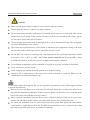
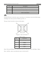
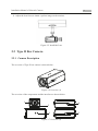
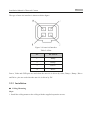
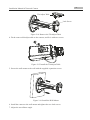
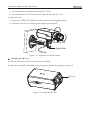
Network Box Camera
Installation Manual
Installation Manual of Network Camera
2
Safety Instruction
These instructions are intended to ensure that the user can use the product correctly to avoid danger
or property loss.
The precaution measure is divided into ‘Warnings’ and ‘Cautions’:
Warnings: Serious injury or death may be caused if any of these warnings are neglected.
Cautions: Injury or equipment damage may be caused if any of these cautions are neglected.
Warnings Follow these safeguards to Cautions Follow these precautions to
prevent serious injury or death.
prevent potential injury or material
damage.
Warnings:
Please adopt the power adapter which can meet the safety extra low voltage (SELV) standard.
And source with 12 VDC or 24 VAC (depending on models) according to the IEC60950-1 and
Limited Power Source standard.
If the product does not work properly, please contact your dealer or the nearest service center.
Never attempt to disassemble the camera yourself. (We shall not assume any responsibility for
problems caused by unauthorized repair or maintenance.)
To reduce the risk of fire or electrical shock, do not expose this product to rain or moisture.
This installation should be made by a qualified service person and should conform to all the local
codes.
Please install blackouts equipment into the power supply circuit for convenient supply
interruption.
Please make sure that the ceiling can support more than 50(N) Newton gravities if the camera is
fixed to the ceiling.
If the product does not work properly, please contact your dealer or the nearest service center.
Never attempt to disassemble the camera yourself. (We shall not assume any responsibility for
problems caused by unauthorized repair or maintenance.)
Installation Manual of Network Camera
3
Cautions:
Make sure the power supply voltage is correct before using the camera.
Do not drop the camera or subject it to physical shock.
Do not touch sensor modules with fingers. If cleaning is necessary, use a clean cloth with a bit of
ethanol and wipe it gently. If the camera will not be used for an extended period of time, put on
the lens cap to protect the sensor from dirt.
Do not aim the camera lens at the strong light such as sun or incandescent lamp. The strong light
can cause fatal damage to the camera.
The sensor may be burned out by a laser beam, so when any laser equipment is being used, make
sure that the surface of the sensor not be exposed to the laser beam.
Do not place the camera in extremely hot, cold temperatures (the operating temperature should
be between -30°C ~ 60°C, or -40°C ~ 60°C if the camera model has an “H” in its suffix ), dusty
or damp environment, and do not expose it to high electromagnetic radiation.
To avoid heat accumulation, good ventilation is required for a proper operating environment.
Keep out of water and any liquid.
While shipping, the camera should be packed in its original packing.
Improper use or replacement of the battery may result in hazard of explosion. Please use the
manufacturer recommended battery type.
For the dome camera that supports IR, you are required to pay attention to the following precautions
to prevent IR reflection:
Dust or grease on the dome cover will cause IR reflection. Please do not remove the dome cover
film until the installation is finished. If there is dus t or grease on the dome cover, clean the dome
cover with clean soft cloth and isopropyl alcohol.
Make certain the installation location does not have reflective surfaces of objects too close to the
camera. The IR light from the camera may reflect back into the lens causing reflection.
The foam ring around the lens (for dome cameras) must be seated flush against the inner surface
of the bubble to isolate the lens from the IR LEDS. Fasten the dome cover to camera body so that
the foam ring and the dome cover are attached seamlessly.
Installation Manual of Network Camera
4
Chapter 1 Introduction
The network camera is a kind of embedded digital surveillance product that combines the features of
both traditional analog camera and the encoder. With a built-in video server, the network camera is
capable of providing real-time video stream compression, processing, video analysis and
transmission simultaneously. Adopting the latest processing chip and hardware platform, the network
camera can be widely applied to various surveillance and image processing systems with high
reliability and stability.
1.1 Applications
The network camera can be used in many surveillance scenes., e.g.:
Network surveillance for over-the-counter activities in the banks, ATMs, supermarkets and
factories.
Remote surveillance systems for nursing homes, kindergartens and schools.
Artificial Intelligent access control systems .
Artificial Intelligent office building/residential compounds management systems.
Unguarded power station and telecommunication base station surveillance systems.
Pipelining and warehousing monitoring systems.
Surveillance systems for airports, railway stations, bus stops, etc.
1.2 Preparations
Make sure the device in the package is in good condition and all the assembly parts are included.
Make sure all the related equipment is power-off during the installation.
Check the specification of the products for the installation environment.
Make sure the power supply is matched with your required voltage to avoid damage.
If the product does not function properly, please contact your dealer or the nearest service center.
Do not disassemble the camera for repair or maintenance by yourself.
Make sure that the wall is strong enough to withstand three times the weight of the camera.
For the camera that supports IR, you are required to pay attention to the following precautions to
prevent IR reflection:
Dust or grease on the dome cover will cause IR reflection. Please do not remove the dome cover
film until the installation is finished. If there is dust or grease on the dome cover, clean the dome
cover with clean soft cloth and isopropyl alcohol.
Installation Manual of Network Camera
5
Make sure that there is no reflective surface too close to the camera lens. The IR light from the
camera may reflect back into the lens causing reflection.
The foam ring around the lens must be seated flush against the inner surface of the bubble to
isolate the lens from the IR LEDS. Fasten the dome cover to camera body so that the foam ring
and the dome cover are attached seamlessly.
6
Installation Manual of Network Camera
Chapter 2 Box Camera Installation
2.1 Type I Box Camera
2.1.1 Camera Description
The overview of Type I box camera is shown below:
Figure 2-1 Overview
Table 2-1 Description
No.
Description
1
Lens Mount
2
Back Focus Ring
3
SD Card Slot
4
Auto-iris Interface
5
6
7
10M/100M Self-adaptive Ethernet Interface
VIDEO OUT: Video Output Interface
AUDIO OUT: Audio Output Interface
8
POWER: Power LED Indicator
9
Power Supply Interface
10
MIC IN: Audio Input Interface
11
D+, D-: RS-485 Interface
7
Installation Manual of Network Camera
No.
Description
12
IN, G: Alarm Input Interface
13
1A, 1B: Alarm Output Interface
14
Grounding
15
RESET: Reset Button
Press RESET about 10s when the camera is powering on or rebooting to restore the default settings,
including the user name, password, IP address, port No., etc.
The type of auto-iris interface is shown as below figure:
Figure 2-2 Auto-iris Interface
Table 2-2 Pins
No.
DC-driven
1
Damp-
2
Damp+
3
Drive+
4
Drive-
Power, Video and GND pins are used when the auto-iris is driven by video; And Damp+, Damp-,
Drive+ and Drive- pins are used when the auto-iris is driven by DC.
8
Installation Manual of Network Camera
2.1.2 Installation
Steps:
1. Fix the mounting bracket to the ceiling.
Expansion Screw
Figure 2-3 Fix Camera Mounting Bracket
2. Aim the screw hole on the camera at the bracket and rotate the camera tightly.
3. Adjust the camera to the desired surveillance angle and tighten the knob on bracket to secure the
camera.
Figure 2-4 Fix the Camera
4. Install the lens.
1). Connect the VIDEO OUT interface of the camera to the debugging monitor.
9
Installation Manual of Network Camera
2). Adjust the lens focus to obtain a perfect image on the monitor.
Figure 2-5 Install the Lens
2.2 Type II Box Camera
2.2.1 Camera Description
The overview of Type II box camera is shown below:
Figure 2-6 Overview (1)
The overview of the components and the interface are shown below:
1
2
3
Figure 2-7 Overview (2)
4
5
10
Installation Manual of Network Camera
The interfaces on the rear panel are shown below:
10
9
8
6
11
7
18
17
16
15
13
14 12
Figure 2-8 Overview (3)
Table 2-3 Description
No.
1
Description
Lens Mount
No.
2
Description
MIC
3
¼-20 UNC Screw Hole
4
Status Indicator
5
Auto-iris Interface
6
LAN(PoE)
7
Power Outlet
8
Reset
9
Micro SD Card Slot
10
Video Out
11
13
15
17
Grounding
RS-232
Alarm In
ABF
12
14
16
18
Alarm Out
RS-485
Audio Out
Audio In
Press RESET about 10s when the camera is powering on or rebooting to restore the default settings,
including the user name, password, IP address, port No., etc.
11
Installation Manual of Network Camera
The type of auto-iris interface is shown as below figure:
Figure 2-9 Auto-iris Interface
Table 2-4 Pins
No.
DC-driven
1
Damp-
2
Damp+
3
Drive+
4
Drive-
Power, Video and GND pins are used when the auto-iris is driven by video; Damp+, Damp-, Drive+
and Drive- pins are used when the auto-iris is driven by DC.
2.2.2 Installation
Ceiling Mounting
Steps:
1. Install the ceiling mount to the ceiling with the supplied expansion screws.
12
Installation Manual of Network Camera
Adjustable Nut
Figure 2-10 Install the Mount
2. Fit the lens (not supplied) to the camera and rotate it to get it tightened.
●
Install the adapter ring to the lens interface if a C-mount lens is used.
● A manual-iris lens can be directly installed to the camera without plugging the power cable of
the auto-iris to the auto-iris interface.
3. Plug the auto-iris cable to the auto-iris interface.
Figure 2-11 Install the Lens
4. Align the screw hole on the camera with the ceiling mount and rotate the camera to get it fixed.
5. Adjust the surveillance angle.
1). Loosen the pan nut to adjust the pan angle [0°-360°].
13
Installation Manual of Network Camera
2). Loosen the knob on the ceiling mount to adjust the tilt angle [0°-90].
6. Adjust the Lens
1). Connect the VIDEO OUT interface of the camera to the debugging monitor.
2). Adjust the Zoom Lever and Focus Lever to obtain a perfect image on the monitor.
Knob
Figure 2-12 Install the Camera to the Mount and Adjust the Angle
Wall Mounting
1. Install the lens (not supplied) to the camera and rotate it to get it tightened.
2. Plug the auto-iris cable to the auto-iris interface.
Figure 2-13 Install the Lens
3. Loosen the lock screw on the mount and remove the tilt adjust table from the wall mount.
14
Installation Manual of Network Camera
Tilt Adjust Table
Lock Screw
Figure 2-14 Remove the Tilt Adjust Table
4. Fit the removed tilt adjust table to the camera, and fix it with two screws.
Figure 2-15 Install the Tilt Adjust Table
5. Secure the wall mount to the wall with the supplied expansion screws.
Figure 2-16 Install the Wall Mount
6. Install the camera to the wall mount and tighten the two lock screws.
7. Adjust the surveillance angle.
15
Installation Manual of Network Camera
1). Loosen the pan nut to adjust the pan angle [0 °-360°].
2). Loosen the knob on the ceiling mount to adjust the tilt angle [0°-±45°].
8. Adjust the Lens
1). Connect the VIDEO OUT interface of the camera to the debugging monitor.
2). Adjust the focus lever to obtain a perfect image on the monitor.
Tilt Adjust Nut
Pan Adjust Nut
Figure 2-17 Adjust the Surveillance Angle
Installing the SD Card
● Insert the SD card to the SD card slot to get it installed.
● Push the inserted SD card slightly to get it sprung by its built-in springing to remove it.
SD Card
Figure 2-18 Install the SD Card