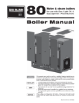
1
Gas-fired
water boiler
Installation Manual
Multiple-boiler systems with
Weil-McLain Easy-Fit® piping
• Selection data
• Installation
• Piping
• Water treatment
with
This manual must only be used by a qualified heating installer/service technician.
Before installing, read all instructions, including this manual, the Ultra Boiler
Manual and all applicable Supplements. Consider all connections to the boilers
before selecting a location and layout. Failure to comply could result in severe
personal injury, death or substantial property damage.
Part No. 550-101-232/0703
GAS-FIRED WATER BOILER
— Installation Manual — Multiple-boiler Systems
Contents
Hazard definitions
.................................................................................................................................. 3
Selection data
Controls ....................................................................................................................
Domestic hot water .................................................................................................
Venting and combustion air....................................................................................
Additional considerations .......................................................................................
3
3
3
3
Ratings and engineering data
.................................................................................................................................. 4
Dimensions
.................................................................................................................................. 6
Placement and mounting information
.................................................................................................................................. 7
Easy-Fit® Piping
Easy-Fit® Piping installation .................................................................................... 8
Piping schematic ...................................................................................................... 9
Easy-Fit® Piping 3-dimensional drawing ............................................................. 10
Easy-Fit® Piping, 4 boilers, 3 water heaters, 3-dimensional .............................. 11
Easy-Fit® Piping with isolation exchanger 3-dim. drawing ............................... 12
Combustion air and vent piping installation
Vent piping ............................................................................................................ 13
Combustion air piping .......................................................................................... 13
Combustion air manifolds .................................................................................... 13
Gas piping
Connecting gas supply piping .............................................................................. 14
Common gas piping installation.......................................................................... 15
Additional instructions
Air for boiler room ventilation ............................................................................. 16
Wiring ..................................................................................................................... 16
Water treatment ................................................................................................... 16
2
Part number 550-101-232/0703
GAS-FIRED WATER BOILER
— Installation Manual — Multiple-boiler Systems
Hazard definitions
The following defined terms are used throughout this manual to bring attention to the presence of hazards of
various risk levels or to important information concerning the life of the product.
Indicates presence of hazards that will
cause severe personal injury, death or
substantial property damage.
Indicates presence of hazards that will or
can cause minor personal injury or
property damage.
Indicates presence of hazards that can
cause severe personal injury, death or
substantial property damage.
Indicates special instructions on
installation, operation or maintenance
that are important but not related to
personal injury or property damage.
Selection data
Controls
Weil-McLain offers an excellent selection of boiler sequencing controls. Refer to individual manuals for details.
Domestic hot water
Refer to Weil-McLain Piping Guides and PLUS Water Heater Manual and Ultra PLUS Supplement for suggested
piping diagrams.
Venting and combustion air
Ultra boilers must be vented individually. Combustion air must be piped to the boiler as well, but
may be manifolded as shown on page 13. Follow Weil-McLain Ultra Boiler Venting Supplement and
Boiler Manual plus information in this manual. Failure to comply will result in severe personal injury
or death.
Additional considerations
1. Review the Ultra Boiler Manual and applicable supplements prior to designing and installing multipleUltra-boiler jobs.
2. Ultra boilers are design-certified for installation on combustible flooring (not carpet).
3. Ultra boilers are tested for 30 P.S.I. working pressure (higher pressure not available).
4. For systems requiring greater than 30 P.S.I. relief valve setting, install a heat exchanger to isolate the boilers from
the main system. See page 12 for suggested piping.
5. Maximum operating temperature of each boiler is 190°F.
This manual provides general guidelines for piping and installation. Your installation must comply
with all applicable local codes.
When using isolation valves on each boiler, some codes may require providing a low water control
and additional limit for each boiler. If desired, consult the codes to determine if exclusion of the
individual boiler isolation valves may allow the use of a single water level control and additional
limit for the entire multiple boiler system.
Part number 550-101-232/0703
3
GAS-FIRED WATER BOILER
— Installation Manual — Multiple-boiler Systems
Ratings and engineering data
Figure 1
Ratings and engineering data (see page 5 for notes)
DOE
4
Part number 550-101-232/0703
GAS-FIRED WATER BOILER
Figure 1
— Installation Manual — Multiple-boiler Systems
Ratings and engineering data (continued)
For simplicity, the table on page 4 lists only systems using multiples of the same Ultra boiler module.
Any combination of Ultra boilers can be installed as a multiple boiler system.
Water header piping
Determine the flow rate that the system header and other
pipes will handle. Then use the table at right to determine
the minimum pipe size. This table shows pipe sizing both
for 350 and 500 milinches per foot head loss. Other pipe
sizing using recognized engineering would be acceptable.
Gas piping
See pages 14 and 15 for gas piping requirements and
connections.
Notes
1. Based on standard test procedures outlined by DOE for
individual boilers.
2. Net I=B=R ratings are based on piping and pickup allowance of 1.15. Consult Technical Services for other allowances.
3. Foundation sizes above provide 6 inches between boilers
and 2 inches from boiler to edge of foundation. Smaller
foundations are possible with reduced service clearances.
See Ultra Boiler Manual for details.
For side-to-side installations, see Figure 3, page 7.
For back-to-back installations, see Figure 4, page 7.
4. Operating weight is the total weight, including water.
Part number 550-101-232/0703
5. Ultra-230 boilers can be vented with 3-inch vent instead
of 4-inch, with the limitations described in the Ultra Boiler
Vent Supplement. (Using the smaller vent pipe reduces
maximum allowable run.)
All Ultra installations require a separate vent pipe and
termination for each boiler. Vent piping cannot be
manifolded. Install and terminate vents as described in
the Ultra Boiler Vent Supplement.
Combustion air piping can be individually piped or
manifolded, as described on page 13. See Ultra Boiler Vent
Supplement for individual air piping.
6. Total amp requirements include boiler circulators.
5
GAS-FIRED WATER BOILER
— Installation Manual — Multiple-boiler Systems
Dimensions
Figure 2
Dimensional data
Notes
1. Boiler supply and return tappings are both 1" NPT.
Connect to headers with 1” pipe for Ultra-80 and
Ultra-105; 1¼" pipe for Ultra-155 and Ultra-230.
For wall-hung boilers, water piping and gas pipe
can be routed through bottom of enclosure using
wall-mounting kit.
6
2. Boiler circulator is shipped loose. Mount
boiler circulator in connecting piping
as shown in this manual. Boiler is
shipped with 1" and 1¼" circulator
flanges.
3. Relief valve is shipped loose. See Boiler
Manual pages 14 and 15 for mounting
details. Relief valve mounts on ¾" street
elbow connected to 1" x 1" x ¾" tee on
boiler supply pipe, as shown in manual.
Part number 550-101-232/0703
GAS-FIRED WATER BOILER
— Installation Manual — Multiple-boiler Systems
Placement and mounting information
REVIEW & COMMENT ONLY
Placement, general
2.
3.
5.
CONFIDENTIAL
Side-to-side installation of multiple Ultra-80/-105/-155/-230 boilers
Figure 4
Back-to-back installation of multiple Ultra-80/-105/-155/-230 boilers
Figure 5
Wall mounting multiple Ultra-80/-105/-155/-230 boilers
1. Locate multiple boilers in boiler
room according to:
• Figure 3 (side-to-side), or
4.
06-24-03
Figure 3
6.
• Figure 4 (back-to-back).
For wall mounting, see below.
Provide indicated clearances
around boilers for access and
servicing. If recommended dimensions are not possible, refer to Ultra Boiler Manual for
minimum clearances. Also follow local codes.
Construct boiler foundation if
boiler room floor is uneven or
if there is a danger of flooding.
Size foundation to allow for
clearance and spacing dimensions shown in either Figure 3
or Figure 4.
Chalkline boiler locations on
foundation or boiler room
floor.
Uncrate, assemble and mount
boilers according to Ultra
Boiler Manual.
Provide clearance for installation of venting, air piping, gas
piping, expansion tank, primary
circulator and other accessories.
Wall mounting
1. Ultra boilers may be wall
mounted, following the instructions in the Ultra Boiler Manual
and the Wall Mounting Supplement.
2. When wall mounting boilers,
provide approximately 6 inches
between boilers for easy removal of boiler jacket door. See
Figure 5.
3. Follow all applicable codes regarding piping, electrical connections and clearances.
4. When wall mounting boilers,
verify the wall construction is
suitable for the structural load.
Part number 550-101-232/0703
7
GAS-FIRED WATER BOILER
— Installation Manual — Multiple-boiler Systems
Easy-Fit® Piping
8
Maximum connected boiler output:
2-inch manifolds — 450 MBH
3-inch manifolds — 1400 MBH
4-inch manifolds — 2900 MBH
Figure 7
Double-sided connection —
Maximum boiler output (each side):
2-inch manifolds — 450 MBH
3-inch manifolds — 1400 MBH
4-inch manifolds — 2900 MBH
REVIEW & COMMENT ONLY
Single-sided connection —
CONFIDENTIAL
1. Main header and Easy-Fit® Manifold pipe sizing.
a. New system:
Refer to Figure 1 on pages 4 and 5 for recommendations.
b. Replacing boilers in an existing system:
Without reducing size, connect system supply and return lines.
Install tees or crosses for Easy-Fit® Manifolds as shown in Figure 6
or 7. Size manifolds to handle total connected boiler ouput as shown.
2. Provide connections in main header for Easy-Fit® Manifolds as close as
possible to the midpoint of multiple boilers.
a. Use tees for four or less boilers, as in Figure 6.
b. Use either tees (Figure 6) or crosses (Figure 7) for five or more boilers.
3. Manifold placement:
a. To alternate spacing for supply and return lines to boilers, reverse the
short-end and long-end of the Manifolds as shown in Figures 6 and
7.
b. Return Manifold must be on the return side of the main and Supply Manifold must be on the supply side of the main. Drawings in
this manual show flow in system main from right to left. For system flowing left to right, reverse the locations of the Manifolds
accordingly.
4. Connect from Easy-Fit® Manifold branches to boiler supply and return connections using 1¼" nominal copper tubing or steel pipe (maximum run 15').
5. Provide a flow/check valve in the supply piping of each boiler as shown
in piping diagrams in this manual. Install an isolation valve on the
supply and return of each boiler as shown. Some local codes may require the use of individual level controls and limits on each boiler
when isolation valves are installed.
6. Install main system air eliminator and primary circulator in supply
piping as shown in piping diagrams. Place expansion tank on suction
side of system circulator as shown.
7. Install condensate drain line piping according to Ultra Boiler Manual.
Condensate drain piping may be connected into a manifold before
connection to a floor drain.
8. Install system accessories as shown in drawings.
9. For some applications, it may be necessary to install a heat exchanger
as shown in Figure 11, page 12, to isolate the boilers from the system. See
notes on page 12 for typical applications.
10. Piping recommendation drawings:
a. Figures 6 and 7 show details of Easy-Fit® Manifolds.
b. Figure 8 is a schematic piping drawing showing the locations of typical boiler piping and system piping, including limits and other devices often required by local codes.
c. Figures 9 and 10 are three-dimensional piping drawings of typical
multiple boiler installation.
d. Figure 11 shows recommended piping when an isolating heat exchanger is needed.
11. If desired, other primary/secondary piping arrangements can be used.
Figure 6
06-24-03
Easy-Fit® Piping installation
Part number 550-101-232/0703
GAS-FIRED WATER BOILER
Piping schematic — Typical piping for multiple Ultra boilers, using Weil-McLain Easy-Fit® Manifolds
06-24-03
CONFIDENTIAL
REVIEW & COMMENT ONLY
Figure 8
— Installation Manual — Multiple-boiler Systems
Flow/check valve (each boiler)
Isolation valves (when used)
Cap
Easy-Fit® Manifold (supply), sized per Fig. 6
or Fig. 7, page 8
5 Easy-Fit® Manifold (return), sized per Fig. 6
or Fig. 7, page 8
6 Primary circulator
7 Expansion tank (diaphragm type)
1
2
3
4
System air eliminator
System automatic air vent
Pressure reducing valve
Check valve or backflow preventer, as
required by applicable codes
12 Isolation valve
13 Cold water supply
14 Supply water temperature control (when
used)
8
9
10
11
15 Low water cutoff (when used) (place above
primary header)
16 Water flow switch (when used)
17 Boiler circulator (each boiler)
18 System supply
19 System return
20 Boiler relief valve and discharge piping, installed
per Ultra Boiler Manual
This manual provides general guidelines for piping and installation. Your installation must comply with all applicable local
codes.
When using isolation valves on each boiler, some codes may require providing a low water control and additional
limit for each boiler. If desired, consult the codes to determine if exclusion of the individual boiler isolation valves
may allow the use of a single water level control and additional limit for the entire multiple boiler system.
Part number 550-101-232/0703
9
GAS-FIRED WATER BOILER
Easy-Fit® Piping
Figure 9
10
(continued)
Typical piping for multiple Ultra boilers, using Weil-McLain Easy-Fit® Manifolds
Flow/check valve (each boiler)
Isolation valves (when used)
Caps
Easy-Fit® Manifold (supply), sized per Fig. 6
or Fig. 7, page 8
5 Easy-Fit® Manifold (return), sized per Fig. 6
or Fig. 7, page 8
1
2
3
4
— Installation Manual — Multiple-boiler Systems
6
7
8
9
13
17
Primary circulator
Expansion tank (diaphragm type)
System air eliminator
System automatic air vent
Cold water supply
Boiler circulator (each boiler)
18 System supply
19 System return
20 Boiler relief valve and discharge piping,
installed per Ultra Boiler Manual
Part number 550-101-232/0703
GAS-FIRED WATER BOILER
Figure 10
— Installation Manual — Multiple-boiler Systems
Typical piping for multiple Ultra boilers, Weil-McLain Easy-Fit® Manifolds, and indirect water heaters
Suggested DHW boiler-side pipe sizing (based
on 500 milinch per foot head loss in piping):
0 – 7 gpm .......................... 1 inch
7 – 16 gpm ........................ 1¼ inch
16 – 24 gpm ...................... 1½ inch
24 – 45 gpm ...................... 2 inch
45 – 75 gpm ...................... 2½ inch
75 –140 gpm ..................... 3 inch
140 – 290 gpm .................. 4 inch
1
2
3
4
5
6
7
8
9
13
Flow/check valve (each boiler)
Isolation valves (when used)
Caps
Easy-Fit® Manifold (supply), sized per Fig. 1
or Fig. 2, page 6
Easy-Fit® Manifold (return), sized per Fig. 1
or Fig. 2, page 6
Primary circulator
Expansion tank (diaphragm type)
System air eliminator
System automatic air vent
Cold water supply
17
18
19
20
21
22
23
24
Boiler circulator (each boiler)
System supply
System return
Boiler relief valve and discharge piping,
installed per Ultra Boiler Manual
Indirect-fired storage water heaters (WeilMcLain PLUS Line shown) — Example is
shown with reverse-return boiler-side piping
using a single circulator. Alternate: each water
heater could have its own circulator.
Boiler water inlet
Boiler water outlet
DHW boiler-side circulator
25 DHW boiler-side supply Easy-Fit® Manifold
26 DHW boiler-side return Easy-Fit® Manifold
27 Flow/check valves (to prevent induced or
gravity flow in heating system or DHW piping)
28 Check valve to prevent heat migration in
heating system
29 See water heater manual for DHW piping —
The DHW piping must also be manifolded
together since the boiler-side piping is
manifolded. If DHW heaters supply separate
DHW circuits, provide an individual circulator
for each water heater, and control each
circulator by its water heater’s aquastat.
This piping is suggested only. The layout above should be controlled with a boiler sequencing panel that provides DHW operation as
well. Wire the heating system circulator to operate only on call for heat. Alternatively, use the boiler sequencing panel to provide
domestic priority by disabling the heating system circulator any time there is a DHW call for heat. The boiler circulators, item 17, must
operate on any call for heat, whether heating system or DHW. Offset the DHW boiler-side supply and return manifolds as shown so
the total run of pipe and fittings to each of the water heaters is approximately equal.
Part number 550-101-232/0703
11
GAS-FIRED WATER BOILER
Easy-Fit® Piping
Figure 11
— Installation Manual — Multiple-boiler Systems
(continued)
Typical piping for multiple Ultra boilers, using Weil-McLain Easy-Fit® Manifolds and heat exchanger
Use isolation heat
exchanger for:
1. Large volume systems with high
mineral content in water.
2. Systems exposed to untreated quantities of makeup water.
3. Old systems severely contaminated
with scale and rust buildup inside
piping and heat distribution units.
4. Process applications.
5. Commercial service water applications.
6. High water pressure applications,
requiring pressure relief setting in
heating system more than 30 PSIG
(tall buildings). See notes below.
1
2
3
4
5
6a
6b
7
8
12
Flow/check valve (each boiler)
Isolation valves (when used)
Cap
Easy-Fit® Manifold (supply), sized per Fig. 6
or Fig. 7, page 8
Easy-Fit® Manifold (return), sized per Fig. 6
or Fig. 7, page 8
Heating system circulator (exchanger
tubeside)
Heat exchanger shellside circulator
Expansion tanks (diaphragm type)
System air eliminator
9
13
17
18
19
20
System automatic air vent
Cold water supply connections
Boiler circulator (each boiler)
Heating system supply
Heating system return
Boiler relief valve and discharge piping,
installed per Ultra Boiler Manual
2.
3.
4.
Notes:
1. Contact heat exchanger manufacturer for
heat exchanger shellside and tubeside piping and circulator requirements. Tubeside
5.
flow and temperatures must meet heating
system requirements.
Contact heat exchanger manufacturer for
sizing heat exchanger.
Heat exchanger shellside circuit requires
its own expansion tank as shown.
Heating system circuit requires its own expansion tank, as shown, plus its own relief valve set to protect heating system and
heat exchanger piping and components.
When individual isolation valves are used,
individual boiler and level controls may
be required.
Part number 550-101-232/0703
GAS-FIRED WATER BOILER
— Installation Manual — Multiple-boiler Systems
Combustion air & vent piping installation
Vent piping
Combustion air manifolds
1. Each boiler requires an individual vent pipe, installed and terminated per the Ultra Boiler Manual
and Ultra Boiler Venting Suppments.
2. The vent pipes of multiple boilers must terminate on
the same side of the building as their air inlet piping,
and per all requirements of the Ultra Boiler Manual
and Vent Supplements.
1. When combustion air supplied from a common air
manifold pipe as in Figure 12, size the common air
duct and louver free area from the minimum free
area given in Figure 1, pages 4 and 5.
2. All joints must be sealed.
3. The air inlet must be located:
• at least 3 feet below any vent located within 10
feet.
• the louver bottom must be 12 inches above grade
or above the snow line.
4. Compensate for louver blockage when calculating
free air openings. Refer to manufacturer’s instructions for size. If unknown use:
a. Wood louvers — 20-25% free area.
b. Metal louvers or grilles — 60-75% free area.
5. Lock open louvers or interlock with boiler controls
to open automatically with boiler operation.
Combustion air piping
1. Provide combustion air piping to each boiler, following all requirements for installation and termination per the Ultra Boiler Manual and Ultra Boiler
Venting Supplements.
2. Combustion air piping can be supplied from a
common combustion air manifold, installed and
terminated as shown in Figure 12, below.
Figure 12
Manifolding combution air piping
Part number 550-101-232/0703
13
GAS-FIRED WATER BOILER
— Installation Manual — Multiple-boiler Systems
Gas piping
Connecting gas supply piping
1. Remove jacket front panel and refer to Figure 13 to
pipe gas to boiler.
a. Install ground joint union for servicing, when
required.
b. Install manual shutoff valve in gas supply piping outside boiler jacket when required by local codes or utility requirements.
c. In Canada — When using manual main shutoff valve, it must be identified by the installer.
2. Wall-mounted boilers
a. Refer to separate Ultra Boiler Wall-mounting
instructions.
b. Gas connection may enter from the bottom of
boiler as explained in the Wall-mounting instructions.
Figure 13
Connecting gas supply piping
3. Support piping with hangers, not by boiler or its
accessories.
4. Purge all air from gas supply piping.
5. Before placing boiler in operation, check boiler and
its gas connection for leaks.
a. Close manual main shutoff valve during any
pressure testing at less than 13" w.c.
b. Disconnect boiler and gas valve from gas supply piping during any pressure testing greater
than 13" w.c.
Do not check for gas leaks with an open
flame — use bubble test. Failure to use
bubble test or check for gas leaks can cause
severe personal injury, death or
substantial property damage.
6. Use pipe dope compatible with propane gases.
Apply sparingly only to male threads of pipe joints
so that pipe dope does not block gas flow.
Failure to apply pipe dope as detailed
above can result in severe personal injury,
death or substantial property damage.
DO NOT adjust or attempt to measure
gas valve outlet pressure. The gas valve is
factory-set for the correct outlet pressure.
This setting is suitable for natural gas and
propane, requiring no field adjustment.
Attempting to alter or measure the gas
valve outlet pressure could result in
damage to the valve, causing potential
severe personal injury, death or
substantial property damage.
Ultra boilers are shipped ready to fire
natural gas ONLY. You must install the
propane orifice if the boiler will be
connected to propane. Failure to comply
could result in severe personal injury, death
or substantial property damage.
Use two wrenches when tightening gas piping at boiler, using one wrench to prevent the boiler gas
line connection from turning. Failure to support the boiler gas connection pipe to prevent it from
turning could damage components.
14
Part number 550-101-232/0703
GAS-FIRED WATER BOILER
— Installation Manual — Multiple-boiler Systems
Common gas piping installation
1. Construct gas header for multiple boilers using Figure 14 and
the sizing tables below. Refer to the National Fuel Gas Code for
other conditions.
2. Provide manual shutoff gas valve and ground joint union as
shown in Figures 13 and 14 for each boiler. When gas line enters from top of the boilerl, the boiler internal gas piping provides a drip leg. See boiler manual for details.
3. A ¾" NPT gas piping riser from header to boiler will be
large enough for most jobs. Check pressure drop.
4. Size gas piping from meter outlet to entrance of gas header in
accordance with Tables 1 and 2 below. For gases with other
specific gravity or for different pressure drop or other pipe
sizes, refer to the National Fuel Gas Code or applicable local
codes.
Pipe lengths in Table 1 are equivalent length of straight pipe.
Convert pipe fittings to equivalent lengths using data from
Table 2.
5. Refer to page 14 of this manual and to the Ultra Boiler Manual
for testing gas piping.
Figure 14
Common gas piping, with manifolded gas header
Table 1
Capacity of gas piping for gas at 0.60 specific
gravity at a pressure drop of 0.30 inches w.c.
Part number 550-101-232/0703
Table 2
Equivalent lengths of straight pipe
for typical gas line fittings
15
GAS-FIRED WATER BOILER
— Installation Manual — Multiple-boiler Systems
Additional instructions
Air for boiler room ventilation
1. Follow instructions in Ultra Boiler Manual to ensure the boiler room provides sufficient
air infiltration.
Wiring
1. Refer to boiler sequencing control instructions and Ultra Boiler Manual for wiring requirements.
Water treatment
Multiple boilers used with large water volume systems will require water
softening and conditioning. Consult a local water treatment company prior to
installation for analysis and recommendations.
Initial fill water may contain enough minerals to produce damaging deposits.
Additional untreated makeup water will increase scale buildup.
Contamination may also come from scale and rust buildup inside the piping
and heat distribution units of an older boiler system replaced with small multiple
boiler units. The result can lead to loss of efficiency and component failure.
1. Follow proper start-up procedure for flushing any contaminants from the entire system
before initial fill.
2. Hot water systems should not require makeup water after initial fill. Use manual feed
water systems or install a water meter to detect leaks.
3. Repair leaks — constant fill water will cause problems.
4. Refer to Ultra Boiler Manual for more information.
16
Part number 550-101-232/0703