1
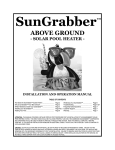
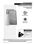
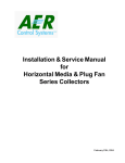
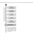
Hot2O Installation Manual
Table of Contents
HOT2O SYSTEM INTRODUCTION.......................................................................................................................3
HOT2O SYSTEM OVERVIEW...............................................................................................................................2
INSTALLATION OVERVIEW.................................................................................................................................6
PLANNING COMPONENT LOCATIONS ............................................................................................................11
SOLAR COLLECTOR INSTALLATION ...............................................................................................................17
SOLAR COMPONENTS INSTALLATION ...........................................................................................................34
TUBING INSTALLATION ....................................................................................................................................49
SOLAR STORAGE TANK ADD-ON KIT INSTALLATION WITH ANTI-SCALD KIT .............................................59
SOLAR CONTROLLER INSTALLATION.............................................................................................................69
SYSTEM STARTUP............................................................................................................................................81
SYSTEM MAINTENANCE...................................................................................................................................85
OPTIONAL KITS .................................................................................................................................................87
SYSTEM TROUBLESHOOTING.........................................................................................................................89
WARRANTY INFORMATION..............................................................................................................................92
Hot2O Installation Manual
Hot2O Installation Manual
HOT2O SYSTEM INTRODUCTION
Welcome to the Hot2O system! We hope you enjoy your new solar water heating system for years to come! Our
goal at FAFCO is to provide you with a high quality, long-lasting product that will save you money over time.
This Hot2O Installation and Maintenance Manual includes information about your system, and provides planning
and installation instructions.
Please view the video and read all supplied materials BEFORE starting your installation process!
Reading the materials will help make sure your installation goes safely and smoothly!
The Hot2O website can provide links to information on energy rebates and tax credits!
FAFCO, Inc.
435 Otterson Drive
Chico, CA. 95928
1-877-554-6826
Visit us on the web at www.hot2o.com
Hot2O Installation Manual
HOT2O SYSTEM OVERVIEW
How the System Works
The FAFCO Hot2O system is designed to capture energy from the sun, and use that energy to help heat your hot
water. The system effectively converts solar energy to heated water. By taking advantage of the sun’s solar
energy, you need less gas or electric power to heat your hot water.
Solar energy is absorbed by the solar collector and is transferred to water as heat. The heated water in the solar
collector transfers its heat to your water heater. Hot water is drawn from your water heater to various household
fixtures and appliances such as clothes washer, dishwasher, bath, shower, and other fixtures.
Since water in your hot water heater is “pre-heated” by solar energy, your water heater doesn’t have to work as
hard. This means that you use less electricity or gas (depending on your system) to provide hot water to your
home! Conserving energy results in lower utility bills!
-2 -
Hot2O Installation Manual
Hot2O Solar Collectors
The solar collectors are mounted on your roof and transfer the sun’s energy to water which is in turn used to
heat your water heater. The best location for the collectors is on a south facing roof, although consideration
must also be given to your water heater location.
-3 -
Hot2O Installation Manual
Electric Water Heater Setup (Single Tank Installation)
The Hot2O system can be installed directly to your electric water heater.
The heat collected by the Hot2O system is transferred through a heat
exchanger and into your hot water heater.
-4 -
Hot2O Installation Manual
Gas or Electric with Solar Storage Tank (Double Tank Installation)
The solar storage tank is required for gas water heaters and
can provide additional capacity for electric water heaters. A
solar storage tank is used to hold water heated by the solar
collectors through the heat exchanger. This solar heated water
is drawn through the water heater and into your home, causing
your water heater to use less energy. The ideal storage tank is
an electric water heater. They are well insulated and already
have the required plumbing connections. A 40 gallon electric
water heater can be purchased for about $250.
-5 -
Hot2O Installation Manual
INSTALLATION OVERVIEW
The Installation manual contains detailed instructions about how to install your new Hot2O system. Each
installation section includes a list of tools and parts needed for that portion of the installation.
You should plan for the installation to take about two days. The length of time it takes to install your system
depends on your experience with Do-It-Yourself projects and the options you chose to install.
Three gallons of undiluted non-toxic propylene glycol can be added to each drainback tank to protect against
freezing. Non-toxic propylene glycol can be purchased at a local automotive store. In some jurisdictions,
plumbing codes require FDA approved propylene glycol be used. Consult your local plumbing code, building
department or a professional plumber to ensure that the approved glycol solution is used.
If you have any questions about installing your system, please visit our website!
-6 -
Hot2O Installation Manual
Tool List
• Safety glasses (recommended)
• 10 Inch Adjustable Wrench
• Knee pads (optional)
• Channel lock pliers
• Sturdy Ladder
• Pliers
• Power Drill
• Wire Cutters
• 1-1/4 “ spade bit or hole cutter bit
• Tin snips
• 1” Hole saw or paddle bit
• Hammer
• 7/8” Hole saw
• Large putty knife
• 1/4 Inch Drill Bit
• Caulking gun
• 9/16 inch socket driver
• Tape measure
• 7/16 Inch Socket
• Stud Finder
• #1 Phillips screw driver
• Level
• #2 Phillips screw driver
-7 -
Hot2O Installation Manual
Important Tubing Installation Notes:
The tubing and push fitting system used in your Hot2O kit are
designed for ease of installation and maintainance, providing a
worry free seal when installed correctly.
When cutting tubing, use the provided cutters and make sure the
cut is even and straight across the end of the tubing. Inspect the
length to be inserted into the fitting for damage.
For all tubing connections, the Hot2O system tubing is inserted into
push fittings.
It is important that the tubing be inserted FULLY into the fitting to
properly seal.
The photo at right shows the markings on the side of the fittings that
indicate how far the tubing should be inserted. Measure the end of
the tubing with these marks to be sure it is fully inserted.
-8 -
Hot2O Installation Manual
WARNING!
Failure to observe safe practices on a roof or other elevated structure may result in
FALLING, which can cause SERIOUS INJURY, or even DEATH!
Unless you are familiar with working on roofs, and have the proper ladders and safety equipment for roof work,
you should consider hiring a professional with the necessary qualifications to do the solar collector installation.
FAFCO strongly recommends that TWO PEOPLE perform the solar collector installation!
Failure to observe safe practices when working on Hot Water heaters may result in
SCALDING, BURNS, or ELECTRICAL SHOCK,
Electric water heaters use 240 Volt AC power. You should open the circuit breaker before working on an electric
water heater. Verify that power is off at the water heater by checking with a volt meter at the junction box on top
of the water heater. If you cannot locate the breaker, open the home main supply breaker. Do not apply power to
an empty electric water heater. The heating elements will be damaged. Gas water heaters (natural gas and
propane) have pilot lights that are always lit. This is a burn hazard. Your pilot should be off, and gas supply
turned off before emptying a gas water heater! FAFCO recommends that you consult a professional plumber or
electrician if you have questions or concerns!
-9 -
Hot2O Installation Manual
CAUTION!
Changes to your existing home plumbing may require building permits. Plumbing installations are
subject to building code restrictions and requirements. Building codes vary greatly between states, and
between counties.
Building code violations could create unsafe conditions in your home and impact future home sale. Check with
your local county building code officials to determine what (if any) permits or restrictions apply to your home
Hot2O Solar Installation! FAFCO is NOT responsible for building code violations!
-10 -
Hot2O Installation Manual
PLANNING COMPONENT LOCATIONS
Planning your component locations is one of the most important steps to make sure your Hot2O system
performs properly. Careful planning also helps make sure your installation process goes as smoothly as
possible!
Solar Collector Planning
It is important to choose the best roof location to install your solar collector. If you are installing more than two
collectors, the roof location must be large enough for the number of solar collectors you plan to install. The main
things to consider for your solar collector site are:
•
•
•
•
•
Distance from your water heater
Roof Direction
Roof Size and Angle
Attic or Crawl Space
Roof Jack Penetrations
Distance From Your Water Heater
The location should be as close as possible to the water heater. The closer your collector is to the water heater,
the shorter the tubing run will be. The maximum recommended tubing length to the solar collector is 100 feet.
The Hot2O system comes with 80 feet of tubing. Additional tubing may be ordered from your dealer. Also
important in determining the length of tubing run is the minimum ¼ inch per foot slope required for system
drainage. As the tubing run gets longer it is more difficult to maintain this slope.
-11 -
Hot2O Installation Manual
Roof Direction
For homes in the northern hemisphere, the best installation site is a roof facing true south. Many homes do not
have a roof that faces directly to true south. Use the following guidelines for choosing which of your roof surfaces
is best for your solar collectors:
•
•
•
•
First choice is a roof facing due south
Second choice is a roof facing between southeast and southwest
Third choice is a roof facing between southeast and northeast, or southwest to northwest
Fourth choice is a roof facing between northwest and northeast
Trees or other buildings must not shade the roof site. Keep in mind that as the seasons change, the sun
changes its location in the sky. Areas that are clear in the winter might be shaded by tree and shrub growth in
the summer. The sun appears lower in the southern sky during winter months, and higher during the summer
months. A solar surveying device (such as the one sold at www.solarpathfinder.com) may help determine the
best location for your solar collection setup.
Roof Angle (Pitch)
The roof should have a minimum angle of 10 degrees. This is sometimes referred to as 2 in 12.
If you have a flat roof or a very steep roof, a rack may provide a way to adjust the mounting angle. Please visit
the FAFCO website for roof rack information.
-12 -
Hot2O Installation Manual
Roof Size
The standard Hot2O kit comes with 48 square feet of solar collector divided between two panels. Your roof will
need a clear area measuring 6½’X14’ for the solar collectors and associated fittings. Add 4½’ to the width for
each additional collector kit you install.
When measuring, keep in mind that the collectors may be oriented in any direction as long as there is minimum
¼ inch per foot tilt for drainage.
Your system requires roof penetrations for the supply and return tubing. Roof jacks are provided to seal the
tubing penetrations. Each penetration will be located within 6-12” of 2 diagonal corners of your solar collector.
Make sure you select a roof site that allows room for your collector AND your roof jacks!
The tubing penetrations on your roof should be located over an attic or crawl space that is not blocked by a
beam, chimney or other obstruction. You will need to enter this area to run supply and return tubing between the
solar collectors and your water heater area. Your attic or crawl space will need to allow the tubing run to slope at
least ¼ inch per foot from the solar collector to your water heater.
-13 -
Hot2O Installation Manual
Item
Description
1
Solar Collectors
2
Lower Roof jack
3
Upper Roof jack
4
Collector Header Straps
5
Collector Body Straps
-14 -
Hot2O Installation Manual
Tubing Run Planning
Now that you know the approximate location of your water heater, solar collectors, and your roof jacks, you can
estimate the length of tubing you will need.
Estimate the distance from BOTH roof jack locations to your water heater. Take into account the vertical AND
horizontal distance the tubing must run. Add an extra ten feet for a safety margin. The total is an estimate of how
much tubing you will need for your installation.
If your tubing runs need to go outside your building, make sure the tubing is covered with UV resistant material
such as UV resistant tape or insulation wrap, or vinyl or metal downspout.
Example Tubing Run
-15 -
Hot2O Installation Manual
Solar Component Planning
The components for your Hot2o system will be hung on a wall in a 2½ - 3’ wide space adjacent to your water
heater or solar storage tank. These components are the drainback tank, circulation module, and controller.
6”
MIN
3
Item
Description
1
Water heater (Single Tank)
Solar Storage Tank (Double tank)
2
Circulation Module
3
Drainback Tank
4
Solar Controller
5
Solar Storage Plumbing
(Double Tank)
6”
MIN
5
3
1
1
36”
MIN
4
4
36”
MIN
2
2
Single Tank Electric
Double Tank Gas
-16 -
Hot2O Installation Manual
SOLAR COLLECTOR INSTALLATION
Solar Collector Installation Overview
Installing your solar collectors correctly is extremely important for proper operation of your Hot2O system. After
reading the planning steps, you have a good idea of your proper roof type and correct collector location.
For the solar collector installation you will need:
Tools
Parts
• Safety glasses (recommended)
• 2 Solar collectors
• Knee pads (optional)
• 2 End caps
• Tape measure
• 2 Header connectors ( ¾” Union)
• Marking tape
• 17 Lag screws, ¼ inch by 2 inch
• 9/16 inch socket driver
• 3 Body straps
• 3 Header straps
NOTE: The procedure included in this manual is for composition asphalt roofs. If you do not have a
composition asphalt roof, look in the section titled “Other Roof Types” for additional
information.
-17 -
Hot2O Installation Manual
-18 -
Hot2O Installation Manual
Item
1
Description
Solar collectors
Comments
Install with minimum ¼” per foot slope
2
¾” End Caps
3
¾” Union Push Fittings
4
Header Strap
Install on high end of collectors. Use roofing sealant with 2” lag
screws
5
Body Strap
Install 2-4” from header and across center of panels. Use roofing
sealant with 2” lag screws 1-2” from panel edge.
6
Roof Jacks
Seal with roof sealant and roofing nails
7
Roof Sensor
From Controller Box
8
¾” to ½” Reducer Push
Wrap with UV tape
Fittings
9
½” Elbow Push Fittings
Wrap with UV tape
10
Tubing
Wrap with UV tape
-19 -
Hot2O Installation Manual
Solar Collector Installation Instructions
1
Carefully carry the solar collector(s) onto the
roof. Do not drag the solar collectors over a
surface that could damage the plastic panels.
Unroll collectors over the eave of your roof,
allowing them to flatten out.
2
On windy days, be careful during this step!
Hold the collectors down if necessary!
3
Connect the solar collector headers with the (2)
¾” union push fittings.
¾” Union
Push Fitting
-20 -
Hot2O Installation Manual
4
5
Lay the collectors in place and mark the four
corner locations.
The roof jacks will be installed diagonally at the
highest header end and lowest. Place the roof
jacks in their approximate location.
Make sure the roof is large enough to fit the
collectors and both roof jacks.
6
Install end caps on each header end opposite of
roof jack locations
-21 -
Hot2O Installation Manual
Install the header straps on the higher collector
header as follows:
6
Start at the center and wrap header strap around
union push fitting and apply roof sealant at the
lag screw location 4-6 inches from header.
Drive in the strap lag screw with a 9/16 socket.
7
Use tin snips to cut off excess strap.
Cover bolt with roof sealant.
8
Repeat steps 6 and 7 for the two end header
straps.
-22 -
Hot2O Installation Manual
9
Lay body strap across collectors, 2-4 inches from
header.
Apply roof sealant at lag screw location, 1-2
inches from collector edge.
Drive a lag bolt through the strap (You can pre10 drill a hole the strap if desired).
Repeat steps 9 and 10 between the panels and
at other edge.
11
Cut off excess roof strap with tin snips.
Cover all bolts with roof sealant.
-23 -
Hot2O Installation Manual
12
Install second body strap 2-4 inches from other
header.
13
Measure to center of collectors and install third
body strap as before.
-24 -
Hot2O Installation Manual
Roof Jack Installation
The roof jacks are used to seal the tubing penetrations for the supply and return tubing that will eventually be
connected to your collectors. Exercise care when installing to insure a good seal.
Tools
Parts
• Safety glasses (recommended)
• 2 Roof jacks
• 1-1/4 “ spade bit or hole cutter bit
• 1 Roof sensor (found in controller box)
• Caulk gun
• 1 Tube of roof sealant
• Tin snips
• 12 Galvanized roofing nails, 1½ inch
• Hammer
• Large putty knife
-25 -
Hot2O Installation Manual
Note: Install the upper roof jack first
1
Place the roof jack over the measured marks.
Mark the roof penetration location (middle of the
roof jack).
Move the roof jack.
2
Drill a 1-1/4 inch roof penetration hole directly
through the roof and into the attic or crawl space.
If a truss blocks the hole, move 1-2 inches either
direction and try again. The roof jack will cover
the unused hole.
3
Cut a notch in the roofing material as pictured.
-26 -
Hot2O Installation Manual
4
Place the roof jack in position over the hole and
determine how far the roof jack needs to slide
under the roofing material.
5
Use a metal putty knife to pry up enough roofing
material for the roof jack to slide under the tile.
Test fit the roof jack by sliding up under the
loosened roofing material.
6
If the roof jack will not slide in place, trim to fit.
Remove the roof jack.
-27 -
Hot2O Installation Manual
Drop the roof sensor wire through the upper roof
penetration.
7
Note: This step only applies to the upper roof
jack.
Place the roof jack back in position over the roof
sensor to check for fit.
8
The roof sensor should have enough lead to
place it out of any potential shadows.
Remove the roof jack.
9
Apply sealant to the area under the loosened
roofing material. Make sure to add enough
sealant to firmly hold the roof jack in place.
-28 -
Hot2O Installation Manual
Apply sealant to the roofing material that will be
covered by the roof jack.
10
On the upper roof jack, make sure not leave
gaps in the sealant around the roof sensor wire!
Use enough sealant to hold the roof jack in
place.
Slide the roof jack under the loosened roofing
11 material and into position. Press down firmly on
the roof jack.
12
Secure the roof jack in place using the roofing
nails provided.
-29 -
Hot2O Installation Manual
Apply sealant to the area between the loosened
roof material and the roof jack. Use enough
13
sealant to seal the roofing material to the roof
jack.
14 Cover the exposed nail heads with roof sealant.
Repeat steps 11 through 24 for the lower roof
15 jack.
Note:
-30 -
Hot2O Installation Manual
16
(Optional) You may paint the roof jacks to match
your roof color, if desired.
-31 -
Hot2O Installation Manual
Other Roof Types
If your roof is not composition asphalt, you will need to determine the best mounting method. For roof surfaces
that are not flat, racks such as the one described will support the solar collectors to reduce the chance of
damage. If you are not sure how to mount the rack to your roof, consult an experienced roofer.
Metal Roofs
If the metal roof is installed on a plywood surface, you may proceed using the normal installation method. If the
metal roof is installed on fir strips, the mounting hardware must penetrate into the fir strip to insure a good seal
and to avoid bending the metal surface. If screw heads protrude above the surface of the roof, a substrate must
be used to prevent damage to the panels.
Open Beam Roofs
Any ceiling with exposed beams must be checked to avoid the screw ends from penetrating into the interior
space. Call FAFCO for alternate installation methods.
Rubber or Asphalt Modified
This type of roof is typically installed flat. Using a 2” to 2-1/2” fender washer under the mounting hardware will
provide additional mounting surface. Be sure to use a generous amount of sealant under the washer, between
the washer and the mounting hardware, and on top of the mounting screw.
-32 -
Hot2O Installation Manual
Roof Rack
This is a suggested method for constructing a rack for mounting solar collectors to flat, tile, gravel, and shake
roofs. Materials may vary, but FAFCO recommends galvanized steel framing, aluminum, PVC or ABS pipe (3/41” DIA). The object is to support the solar collector off the roof surface to avoid abrasion and conforming to
roofing shape (barrel tile).
• Adjust width (66” MIN) to
mount to attic trusses or
barrel tile peaks.
• Mount to roof at minimum 6
locations, 1 in each corner
and 1 in the middle of each
side.
• Use appropriate screw for
mounting directly to tile.
• Use lag screws to attic
trusses when possible.
• For
flat
roofs,
add
approximately 28” length
legs for vertical mount, 12”
legs for horizontal mount at high end.
Note:
FAFCO assumes no responsibility or liability for roof rack installation. FAFCO offers no
warranty coverage for roof rack installation. Roof rack installation is the sole responsibility of
the owner. FAFCO suggests contacting a licensed contractor for assistance, if necessary.
-33 -
Hot2O Installation Manual
SOLAR COMPONENTS INSTALLATION
Solar Components Installation Overview
Tubing and push fittings are used in this section. Review the Installation Overview section as to their installation.
For the solar components installation you will need:
-34 -
Hot2O Installation Manual
Tools
• Safety Glasses (Recommended)
Parts
• 1 Drainback Tank
• Sturdy Step Ladder
• 2 Lag Screws With Washers
• Tape Measure
• 1 Circulation Module
• Marking Pencil
• 2 Lag Screws
• Power Drill
• 1 Stainless Steel Flexible Hose, ¾ Inch Fip
• 1/4 Inch Drill Bit
• 1 Stainless Steel Flexible Hose, ½Inch Fip
• 9/16” Socket
• 7/16” Socket
• 10 Inch Adjustable Wrench
• 1 Coaxial Tank Adapter
• Pipe Wrench (Optional)
• 1 Roll Teflon Tape
• 1 Tube Pipe Thread Compound
• 2 Reducer Push Fittings (¾” To ½”)
• Channel Lock Pliers
• 1 Coupler, ¾” (As Needed)
• #2 Phillips Screwdriver Or Bit
• 1 Nipple, ¾” (As Needed)
• Stud Finder
• Tubing
• Level
• 1 Throttle Valve
• 1 Drain Valve
-35 -
Hot2O Installation Manual
4
6” MIN
Item Description
Existing Water heater (Single tank)
1
OR
Solar Storage Tank (Double Tank)
5
1
11
36” MIN
2
Coaxial tank adapter
3
Drain Bib
4
Throttle Valve
5
Drainback Tank
6
Circulation Module
7
½” Flexible Stainless Steel Hose
8
¾” Flexible Stainless Steel Hose
9
10
11
¾” to ½” Reducer
Drain Valve
Tubing
10
8
2
3
7
9
Comments
Be careful not to cross thread. Use
Teflon tape and pipe thread
compound when installing into tank.
Use Teflon tape and pipe thread
compound
Mount to stud, minimum 6” from
ceiling and 36” above Circulation
Module
Mount to stud on or above floor
Teflon tape and pipe thread
compound not necessary
Teflon tape and pipe thread
compound not necessary
6
-36 -
Hot2O Installation Manual
SET STORAGE TANK IN PLACE
This installation step only applies to double tank Hot2O systems. If you have a single tank electric system, skip
this step!
1
2
Assemble stand if needed to bring storage
tank height within 6 inches of water heater
height and set adjacent to water heater.
Place water heater on stand and strap if
required by local building code.
-37 -
Hot2O Installation Manual
Turn Off and Drain Water Heater
Make sure the water heater is OFF
1
• Shut off the gas supply (gas water
heaters)
• Open the circuit breaker and verify
with a volt meter at the top of the
water heater (electric water heaters)
2
Shut the water heater inlet valve. This valve
is usually a lever valve near the top, righthand side of the water heater (shown shut).
3
Shut off water to the home at the main
water shutoff (shown open).
-38 -
Hot2O Installation Manual
Connect a garden hose to the drain
connection at the bottom of your water
heater.
4
Make sure discharge end of the hose is in a
safe place for hot water to flow.
Slowly open the drain valve.
5
As water heater is draining, open the
pressure relief valve on the side or top of
the heater.
When heater is empty, remove hose, close
drain valve, and relief valve
-39 -
Hot2O Installation Manual
Installing the Coaxial Tank Adaptor
For double tank setups, perform these steps on the storage tank.
For single tank setups, perform these steps on your existing electric water heater.
1
Carefully remove the drain fitting from the
bottom of the unit.
2
Inspect the open drain hole for rust or dirt.
Clean if needed.
3
Wrap the coaxial tank adapter threads with
Teflon tape.
-40 -
Hot2O Installation Manual
4
Coat the coaxial tank adapter threads with
pipe thread compound. This “double seal”
prevents leakage from the coaxial
connector!
Install the coaxial tank adapter into the drain
hole. Be careful not to cross-thread the
adapter. Do not over tighten.
5
6
The thichkness of water heater sidewalls
vary. You may need to extend the coaxial
tank adapter using the ¾” nipple and ¾”
coupler provided. Use Teflon tape and pipe
thread compound on all connections.
Wrap the coaxial tank adapter drain threads
with Teflon tape, and then coat the
threads with pipe thread compound.
-41 -
Hot2O Installation Manual
7
Screw the new drain fitting onto the coaxial
tank adapter.
-42 -
Hot2O Installation Manual
Mounting the Drainback Tank
1
Locate a wall stud near the desired
drainback tank mounting position.
Hold the drainback tank in place near the
mounting site.
2
The top of the drainback tank should be
between 6 and 12 inches from the ceiling.
Hold the drainback tank in place over the
new mark.
4
Raise the drainback tank straight upwards
until the tubing (at the top) touches the
ceiling. Mark the location where the tubing
touches the ceiling.
Make a second mark directly above the
sight glass tube.
-43 -
Hot2O Installation Manual
5
Support the drainback tank such that the
bottom fitting is off the floor. Pull tubing out
about 6 inches and push on throttle valve.
6
Push tubing back into drainback tank until
end of tube touches the bottom of the tank.
Move the drainback tank back to the correct
mounting location.
7
Drive the top bolt into the wall stud. Do not
tighten all the way.
If you miss the wall stud, repeat your
measurements!
-44 -
Hot2O Installation Manual
7
Use a level to set the drainback tank
straight.
Drive the bottom bolt into the wall stud. Do
not tighten all the way. If you miss the wall
stud, repeat your measurements!
8
Recheck that the tank is level.
Finish mounting the drainback tank by
tightening the mounting bolts (top and
bottom).
-45 -
Hot2O Installation Manual
Installing the Circulation Module
1
Mark two hole locations 6-¾ inches apart on
the wall along the stud at least 4” off the
floor to the bottom location and 38” from the
top location and the bottom of the drainback
tank.
Check for level and drive two lag screws
leaving about a ¼ gap to the wall.
Carefully set the circulation module onto the
mounting bolts.
2
3
Make sure the mounting is sturdy. If
necessary, adjust the mounting bolts for a
tight fit.
Connect the flexible hoses to the threaded
pipes on top of the circulation module. The
flexible hoses only fit one way (small to
small and large to large)
Do not use Teflon tape or pipe thread
compound on these connectors!
-46 -
Hot2O Installation Manual
4
Screw the supply side (larger) flexible hose
onto the coaxial tank adapter opposite from
the drain valve. Do not over tighten this
connection!
Do NOT use Teflon tape on this connection!
5
Screw the return side (smaller) flexible hose
onto the coaxial tank adapter. Do not over
tighten this connection!
Do NOT use Teflon tape on this connection!
6
Push the ¾ to ½ inch reducer push fittings
over the smooth pipes on top of the
circulation module as shown.
-47 -
Hot2O Installation Manual
7
The pipe must be inserted to the indicated
depth to ensure a good seal.
Cut 6-8 inches of tubing and install on
circulation module to connection marked
“FROM BOTTOM OF DRAINBACK TANK.”
9
Install drain valve.
Cut length of tubing to install between drain
valve and bottom of drainback tank and
install.
-48 -
Hot2O Installation Manual
TUBING INSTALLATION
Tubing Installation Overview
Follow these instructions carefully! Good planning and careful measurements make your installation process
much easier and MUCH SAFER!!
Tubing and push fittings are used in this section. Review the Installation Overview section as to their installation.
After completing the solar collector and solar components installations, you need to connect tubing between the
two locations! There will be tubing runs in the following locations:
• From the solar collector headers to the roof jacks
• Inside the attic or crawl space from the roof jacks to the drainback tank and circulation module
Remember to maintain a ¼ inch per foot slope for complete draining of the system!.
If your tubing runs have to go outside your building, make sure the tubing is covered with UV resistant tape, or
use some other method to protect the tubing. Examples of how to shield the tubing include UV-resistant
insulation and tape, and vinyl or metal rain gutter.
This tubing is NOT UV resistant! Do not leave tubing in sunlight! Use UV tape to wrap all tubing and tubing
connectors that are exposed to sunlight!
-49 -
Hot2O Installation Manual
Tubing Installation Tools List
Tools
• Safety glasses (recommended)
Parts
• 1 tubing roll (80 feet)
• Sturdy step ladder
• 8 Tubing clips
• Tubing cutter
• 8 screws
• Tape measure
• Zip ties (in controller box)
• Marking pencil
• 1 Two-Lead cable for Sensor (50
feet). Located in controller box. for
the single tank kit, this lead is
attached to the controller.
• Power Drill
• 1 Splice, Located in controller box
• 1” Hole saw or paddle bit
• 2 Reducer push fittings (¾” to ½”)
• #2 Phillips screwdriver or bit
• 4 elbow fittings
• Pliers
• UV-resistant tape
• ¼” Drill Bit
-50 -
Hot2O Installation Manual
Example Tubing Run From Upper Roof Jack
-51 -
Hot2O Installation Manual
Tubing Installation Instructions
1
Drill two 1-inch holes through the ceiling at the
previously marked locations above the drainback
tank.
2
Push tubing up through hole on right.
3
In attic, pull enough tubing through hole to reach the
lower roof jack.
-52 -
Hot2O Installation Manual
4
With helper on roof, push approximately 1 foot of
tubing through the lower roof jack penetration.
Tubing may be lubricated with silicon grease or
water.
5
Install tubing clip up by the roof jack and clip tubing in
place.
6
Continue installing clips every 3 to 4 feet maintaining
a minimum slope toward the ceiling penetration of ¼”
per foot.
-53 -
Hot2O Installation Manual
7
Cut tubing to length to connect to the circulation
module at outlet marked “TO SOLAR COLLECTOR
AT CLOSEST BOTTOM HEADER”.
8
Slide tubing flange over tubing up to ceiling.
9
Install to circulation module.
-54 -
Hot2O Installation Manual
Push tubing through ceiling hole on left and repeat
10 steps 3-6 for the right ceiling hole to upper roof jack
tubing run.
Cut tubing to length, push tubing flange on tube and
connect to throttle valve.
11 .
Remember to measure against valve to the indicated
mark before cutting.
12 Drill a ¼” hole about 1½-2” from the right ceiling hole.
-55 -
Hot2O Installation Manual
Push the two-lead roof sensor wire through. For
single tank setups, this wire is attached to the solar
13 controller.
Pull wire into attic. Strip of about 1 inch of jacket to
expose leads. Cut off stripped ends of roof sensor
14
wire and splice to the roof sensor wire. Make sure
wires are fully inserted before clamping closed.
15
Zip tie the sensor cable to the tubing every 3 to 4 feet
for support.
16 Cut about four feet of tubing and take it to the roof.
-56 -
Hot2O Installation Manual
17
Install ¾ to ½ inch reducers on the collector headers
at roof penetrations.
18
At the lower roof jack, cut penetrating tubing to 4
inches. Install elbow connector.
Cut a length of tubing to reach between elbow and
connector on collector. Remember to measure
19 against connectors to the indicated marks.
Install tubing.
-57 -
Hot2O Installation Manual
Push tubing back through the roof jack until elbow is
20 flush. Wrap exposed tubing and connectors with UVresistant tape.
21
Repeat steps 15 through 18 at upper roof jack
location.
22
Use roof sealant to affix roof sensor to roof. The roof
sensor should not be placed in a shadow!
-58 -
Hot2O Installation Manual
SOLAR STORAGE TANK ADD-ON KIT INSTALLATION WITH ANTI-SCALD KIT
Double tank setups require modifications to your water heater plumbing.
Tools
• Safety glasses (recommended)
Parts
Solar Storage Add-on Kit PN 730
• Adjustable wrench
• 1 By-pass valve
• Channel lock pliers
• 4 Copper flex hose with adaptors
• 1 Compression to ¾” NPT adaptor (if
needed)
• 3 Dielectric ¾” nipples
Anti-scald Kit PN 733
• 1 Anti-scald valve
• 3 Copper flex hose with adaptors
• 1 Brass tee, ¾”
• 2 Nipple, ¾”
• 2 Dielectric nipple, ¾”
• 1 Compression to ¾” NPT adaptor (if
needed)
• Teflon Tape
• Pipe thread compound
-59 -
Hot2O Installation Manual
Solar Storage Tank Add_on Kit with Anti-scald Kit
HOT
COLD
BYPASS
SIDE
5
4
Item
1
3
6
Description
Existing Water
Heater
2
Solar Storage
Tank
3
Anti-Scald Valve
4
Brass Tee
5
Bypass Valve
6
Copper flex hoses
with adapters
2
1
Comments
Note orientation. Black
valve actuator is on
storage tank side.
-60 -
Hot2O Installation Manual
HOT
WATER
WATER
SUPPLY
SHUT-OFF
VALVE
BI-PASS
VALVE
ANTI-SCALD
VALVE (OPTIONAL)
HOT OUT
COLD IN
HOT OUT
WATER
HEATER
COLD IN
SOLAR
STORAGE
TANK
Plumbing Connections with Anti-Scald Valve
-61 -
Hot2O Installation Manual
All pipe thread connections need to be wrapped with Teflon tape and coated with pipe thread compound, all
copper flex hose connections do not.
1
Remove heater vent and vent cap from the water
heater (gas only)
2
Disconnect the water heater hoses. Replace if
needed.
3
Check the nipples in the water heater and replace if
they are not dielectric. Use Teflon tape and pipe
thread compound
-62 -
Hot2O Installation Manual
4
Remove the adapters from the copper flex hoses
5
Wrap the hot water out from the water heater with
Teflon tape, coat with pipe thread compound and
install anti-scald valve, connection marked “H”.
6
Wrap pipe thread side of adapter with Teflon tape
and coat with pipe thread compound. Install on
“MIX” side of anti-scald valve.
-63 -
Hot2O Installation Manual
7
Attach hot water hose to “MIX”.
8
Wrap threads of ¾” nipple with Teflon tape and coat
with pipe thread compound. Install on “C” side of
anti-scald valve.
9
Wrap exposed threads on nipple with Teflon tape
and coat with pipe thread compound. Install ¾” brass
tee.
-64 -
Hot2O Installation Manual
10 Wrap pipe thread side of 2 adapters with Teflon tape
and coat with pipe thread compound. Install on both
sides of brass tee.
11 Connect cold water in hose to one side of brass tee.
12 Connect copper flex hose to other side of tee.
-65 -
Hot2O Installation Manual
13 Install copper flex hose on cold water inlet to water
heater.
14 Replace heater vent cap
15 Replace heater vent
-66 -
Hot2O Installation Manual
16 Prepare 4 adapters with Teflon tape and pipe thread
compound on pipe threads. Install into bypass valve
17 Install 2 copper flex hoses on the solar storage tank
18 Note the orientation of the bypass valve. The black
valve actuator is on storage tank side.
Attach copper flex hose from the brass tee to the top
of the bypass valve and the copper flex hose from
the water heater cold inlet to the bottom of the
bypass valve.
-67 -
Hot2O Installation Manual
19 Attach the copper flex hoses from the solar storage
tank to the other side of the bypass valve such that
the hot water out goes to the cold water in of the
water heater.
20 Make sure all connections are tight.
If you have any questions or concerns about your plumbing,
please contact a licensed plumber for assistance!
A local, licensed professional will be able to help with
plumbing connections as well as any building code
concerns.
-68 -
Hot2O Installation Manual
SOLAR CONTROLLER INSTALLATION
Solar Controller Installation Overview
The Solar Controller shipped with your base kit is different depending on whether you chose the solar storage
tank option used with gas or electric water heaters, or are installing directly into your electric water heater.
If you are installing into your electric water heater, the controller shipped with your base kit (PN 760) has the
ability to control the bottom heating element in the water heater. This unit is factory set to allow the element to
operate from 7:00pm to 5:00am daily every day. The controller also monitors the roof temperature and the tank
temperature to determine the operation of the solar system.
The controller shipped with base kit for the solar storage tank option (PN 760-1) monitors the roof temperature
and the tank temperature to determine the operation of the solar system.
-69 -
Hot2O Installation Manual
Single Tank Solar Controller Installation for Electric Water Heater, base kit PN 760
•
•
•
•
•
TURN OFF ALL POWER TO THE ELECTRIC WATER HEATER
Mount the controller
Remove and modify the water heater lower access cover
Install heating element bypass wiring
Install a heater tank temperature sensor
Tools
Parts
• Safety glasses (recommended)
• 1 Controller
• #1 Phillips screw driver
• 4 Mounting screws
• #2 Phillips screw driver
• 7/8” Hole saw
• Drill motor
-70 -
Hot2O Installation Manual
TURN OFF ALL POWER TO THE ELECTRIC WATER HEATER
1
2
Mount the solar controller onto the wall or on the water
heater.
Remove the lower element access cover plate.
Remove insulation and plastic cover.
You need to drill a hole in the cover plate.
3
To determine best location for the hole, hold the cover
plate next to the wiring and mark the desired hole
location with your finger.
-71 -
Hot2O Installation Manual
4
Drill a 7/8 inch hole in the cover plate.
5
Remove connector from leads and mounting nut and
washer from conduit
5
Insert the wiring end of the conduit through the hole
and fasten conduit to cover plate.
-72 -
Hot2O Installation Manual
6
Find the wire that connects the thermostat to the
heater element and disconnect at the element.
7
Insert the wire you just removed into the connector at
the end of the black wire coming out of the controller
conduit and tighten screw to secure
9
Attach the black wire coming from the controller
conduit to the open terminal of the heater element.
-73 -
Hot2O Installation Manual
10 Locate the sensor labeled “2” attached to the controller
11
Insert in the water heater underneath the insulation to
allow good contact with the tank wall.
12
Replace the lower heater access cover plate. Be
careful not to pinch or cut the sensor wire.
-74 -
Hot2O Installation Manual
13
Use zip ties as needed to route sensor wires from the
heater and the roof sensors.
Plug the controller into a 120-volt outlet.
Extension cords are okay.
After going through a startup sequence, the display will
show the temperature at the roof, t-1. To display the
temperature at the tank, use the down arrow to select
15 t-2. Press and release “SET” to view the time and day
of week. If “Er1” is displayed, check the connection to
the roof sensor, if “Er2” is displayed, check the
connection to the tank sensor.
DO NOT PLUG CIRCULATION MODULE INTO
CONTROLLER UNTIL YOU HAVE FILLED YOUR
WATER HEATER AND DRAINBACK TANK!!
-75 -
Hot2O Installation Manual
Double Tank Solar Controller Installation Gas or Electric With Solar Storage Tank, Base Kit PN 760-1
•
•
•
•
Mount the controller
Install the water heater temperature sensor
Splice or strip roof and heater sensor wires
Connect sensor wires into controller
Tools
Parts
• Safety glasses (recommended)
• 1 Controller
• #2 Phillips screw driver
• 3 Mounting screws
• 7/8” Hole saw
• 1 Splice
• Drill motor
• Wire stripper/cutter
• Pliers
-76 -
Hot2O Installation Manual
Double Tank Solar Controller Installation Instructions
1
Remove cover plate from the controller and
mount the solar controller onto the wall or on
the solar storage tank.
Remove the lower access cover plate from the
storage tank.
2
Remove insulation and plastic cover.
3
Locate the tank sensor in the controller box.
-77 -
Hot2O Installation Manual
4
Insert in the water heater underneath the
insulation to allow good contact with the tank
wall.
Run the end of the sensor wire out the bottom
or side of the access opening.
5
Strip jacket on sensor wire back about 1 inch.
Cut off stripped ends of sensor leads and splice
to sensor wire. Insert wires as far as they will
go into splice before clamping closed.
Cut both the roof sensor and tank sensor wires
to length such that they can enter through the
bottom of the controller
5
Strip off about 1 inch of jacket exposing the
individual wires.
Strip about ¼ inch of the insulation off each
wire.
-78 -
Hot2O Installation Manual
Attach the ROOF SENSOR wires in the
terminal block connectors for T1.
6
Use a small screwdriver to push the white tab
up, then insert the wire into the terminal and
release the tab.
It does not matter which side is red and which
is black.
7
8
Repeat the process to connect the storage tank
sensor to the “T2” terminal.
Replace the controller cover plate and Plug the
controller into a 120-volt outlet.
Extension cords are okay.
-79 -
Hot2O Installation Manual
10
The display shows the temperatures at the roof
or at the tank. Use the arrow buttons to toggle
between the two.
If the display does not show a temperature
when T1 is selected, check the connections to
11 the roof sensor. Likewise, when T2 is selected
and not temperature is displayed, check the
tank sensor connections.
Note: Instructions
for
operating
the
controller are in the controller box!
DO NOT PLUG CIRCULATION MODULE INTO THE CONTROLLER UNTIL YOU HAVE FILLED YOUR
WATER HEATER AND DRAINBACK TANK!!
-80 -
Hot2O Installation Manual
SYSTEM STARTUP
The installation process is ALMOST complete! Follow these steps to start up your system.
1
Remove the aerator screen from a faucet in
the home and turn on the hot water.
Alternatively, open the hot water on a bathtub
faucet,
2
Open main water valve to house.
3
Open water valve to Water Heater.
-81 -
Hot2O Installation Manual
4
Check your plumbing for leaks and repair as
needed.
5
Keep faucet open until air is purged.
6
Turn on water heater
For electric water heater, turn circuit breaker
on
For gas water heater, turn on gas and follow
the instructions on your water heater to light
pilot.
7
Fill drainback tank to top of sight glass. For
additional freeze protection, add three gallons
of non-toxic propylene glycol prior to filling the
drainback tank with water.
-82 -
Hot2O Installation Manual
8
Inspect tank fittings for leaks and tighten if
needed.
9
Plug circulation module directly into a 120VAC
outlet and check for audible operation of
circulation module pumps
Within 5 minutes, the water level in the
drainback tank will stabilize.
10
Inspect all connections including those on the
roof for leaks and repair as needed.
-83 -
Hot2O Installation Manual
11
Plug circulation
controller.
12
Single Tank
module
into
the
solar
Set time and day of week using supplied
instructions
13
Double Tank
Set switch on side of controller to AUTO
(middle position).
Remember: The Hot2O website has links to information on energy rebates and tax credits!
-84 -
Hot2O Installation Manual
SYSTEM MAINTENANCE
Maximizing Energy Savings
This system is designed to operate automatically. However, due to weather variation and different amounts of
sunlight available throughout the year, the savings will vary from month to month. It is possible to maximize
energy savings by scheduling large hot water usage (such as laundry and dishwasher) for the afternoon.
Turning the Solar System Off
In the unlikely event of a problem, it is possible to turn the solar system off while still allowing the water heater to
provide hot water for the house. Set the solar controller to “manual off” (double tank) or disconnect the power
cord to the circulation module.
Completely Draining the System
If it is necessary to drain the system for service, turn the system off. Install a 5/8” outside diameter tube or
equivalent to the drain valve above the circulation module and let the water drain to a safe location outside.
Controller Working Properly (Monthly Check Up)
The solar system uses an automatic controller that turns the solar system on when there is adequate solar
energy to capture. To ensure that your solar collectors are turning on during sunny conditions, and not during
nighttime, check on a hot day around noon to make sure your system is on. Then check to ensure the system is
off at night.
-85 -
Hot2O Installation Manual
Water Level (Monthly Check Up)
Check your water level when the solar collector is active. The water level should be above the minimum indicator
on the drainback tank sight glass. If water is needed, turn off the system first and allow the water to drain into the
drainback tank before adding water.
Plumbing on Roof (Every Other Month)
Every other month it’s advisable to inspect the tubing and push fitting connections on the roof to ensure they are
still adequately protected from sunlight exposure. Insulation can deteriorate and animals or debris can damage it
or remove it completely thereby reducing the efficiency of the system and leaving the underlying components
vulnerable to damage. If there are any parts of the tubing or push fittings exposed to sunlight, cover them up with
additional insulation and UV resistant tape.
Roof Jacks (Before the Rainy Season)
Inspect the roof jacks to make sure they still appear to have a watertight seal. Add polyurethane caulking if there
is any chance of water getting around the roof jack.
If you have any questions about your Hot2O system maintenance,
visit our website for assistance!!!
-86 -
Hot2O Installation Manual
OPTIONAL KITS
PN 731 Solar Collector Add-on Kit
The Solar Collector Add-on Kit adds 48 square feet of collector to your system. It comes with everything you
need to add on to an existing system.
Includes:
(2) 2’X12’ solar collectors
(4) ¾” union fittings
(3) collector body straps
(3) collector header straps
(12) 2”X¼” lag screws
(1) roof jack
(1) roof jack plug
(1) drainback tank
(4) 90º ½” elbow push fittings
(2) ½” tee push fittings
-87 -
Hot2O Installation Manual
PN 733 Anti-Scald Valve Kit
This option adds additional protection against accidental scalding hot water getting to your faucets. The kit
provides an adjustable maximum hot water temperature between 120°F and 145°F.
Includes:
(1) anti scald mixing valve
(3) 2’ long ¾” copper flex hoses
(1) ¾” brass tee
(2) ¾” brass nipples
(2) ¾” dielectric nipples
(2) ¾” compression to ¾” NPT adapters
(1) roll Teflon tape
PN 730 Solar Storage Tank Add-on Kit
Use this kit with a solar storage tank to increase your hot water capacity.
Includes:
(1) bypass valve
(4) 2’ long ¾” copper flex hoses
(3) ¾” dielectric nipples
(1) ) ¾” compression to ¾” NPT adapter
-88 -
Hot2O Installation Manual
SYSTEM TROUBLESHOOTING
Problems with your Hot2O system usually fall into two categories:
• Problems with Flow
• Leaks
Problems with flow
The controller doesn’t seem to turn on the pumps
Verify the temperature difference between the roof and the tank is greater than 10ºF.
Check that circulation module is plugged into the controller.
Verify the controller has been properly programmed.
Check the pumps and verify that they are running. Open the circulation module and touch the pump housing to
verify they are warm or hot. You should feel a slight vibration or hear a slight hum. You can also use a
voltmeter to check for power to them.
-89 -
Hot2O Installation Manual
The water level in the drainback sight glass does not drop when the solar heater is active
Verify that the circulation module is plugged into the controller.
Use a voltmeter or power sensor to check for power to circulation module outlet on the controller.
Indication of solar-side pump failure, contact FAFCO Inc.
I’m not getting hot water
Verify that the controller is properly set. Refer to the section on setting the controller.
Try adjusting the anti-scald valve to allow for hotter water. This is often the cause.
The solar collector(s) will heat the tank best during clear sky days in the summer, late spring, and early fall.
Adding additional solar collectors will increase performance.
You may need a bigger tank or a second solar storage tank.
If necessary, turn up the thermostat(s) on your water heater. Refer to your water heater instruction manual for
proper thermostat adjustment and setting.
For single tank electric tanks, verify that the bottom element is activated or solar is providing sufficient heat
during large draws.
-90 -
Hot2O Installation Manual
Problems with water leaks…
Tubing and fitting leaks
Make sure that the tubing is fully inserted into the fittings. If leak persists, remove fitting and check tubing
damage and end is cut square.
Solar Collectors Leaks
Verify that the leak is not rain or condensation dripping from the solar collectors.
Leak repair kits (PN 262) are available to repair panel leaks that can occur in the solar collectors.
Drainback Tank Leaks
Inspect and tighten fittings.
Circulation Module Leaks
Open case and inspect and tighten fittings.
If you have any questions about troubleshooting your Hot2O system,
visit our website for assistance!!!
-91 -
Hot2O Installation Manual
WARRANTY INFORMATION
LIMITED THREE-YEAR WARRANTY FOR THE FAFCO SOLAR WATER HEATER
by FAFCO INCORPORATED (FAFCO)
435 Otterson Drive, Chico, California 95928, Phone (530) 332-2100
1.
SCOPE OF COVERAGE:
This warranty applies only to new SDHW solar systems manufactured by FAFCO and installed according
to the FAFCO manual and instructions at a premises owned by the consumer/buyer. This warranty applies
only to systems installed at a residence.
2.
IDENTITY OF WARRANTOR AND WARRANTEE:
The warranty is extended by FAFCO and is extended only to the original consumer/buyer of the solar
collector. This warranty is not assignable and applies only to the original buyer. This warranty terminates
upon the sale by the buyer of the premises at which the system was installed.
3.
FAFCO’S WARRANTY: LIMITED THREE-YEAR WARRANTY ON SOLAR COLLECTOR, ONE YEAR ON
SYSTEM COMPONENTS:
A.
The SDHW solar collectors are warranted to be free from defects in materials and workmanship
under normal use and with normal service for the heating of domestic hot water for three (3) years
from date of purchase, subject to the terms, conditions, and limitations described herein.
B.
All other components of the FAFCO HOT2O system are warranted to be free from defects in
materials and workmanship under normal use and service for the heating of domestic hot water for
-92 -
Hot2O Installation Manual
one (1) years from date of purchase, subject to the terms, conditions, and limitations described
herein.
FAFCO’s responsibility for any covered defect during the warranty period shall be limited to the
replacement of the defective parts as described below.
4.
WHAT IS NOT COVERED:
A.
EXCLUSIONS: The above warranty does not apply:
1. To conditions resulting from a defect in a component or part which is not part of the FAFCO
collector or system.
2. To conditions resulting, directly or indirectly, from any failure to comply with FAFCO’s manual or
any of FAFCO’s installation or operating instructions.
3. To any conditions, defects, or loss of function, including without limitation internal freezing,
resulting directly or indirectly from any failure to perform all reasonable and necessary
maintenance and repair in accordance with FAFCO’s operating and maintenance instructions.
4. To any conditions, defects, or loss of function resulting from any misuse, abuse, neglect, accident,
or alterations.
5. To fading and minor deterioration of exterior surfaces resulting from exposure to the elements,
except to the extent that such conditions have a material effect on the system’s performance.
-93 -
Hot2O Installation Manual
B.
NO WARRANTY OF PERFORMANCE OF THE SOLAR COLLECTORS AND SYSTEM: FAFCO
makes no warranty as to the level of performance of its solar collectors, or as to any particular
temperature or level to which the water will be heated. Actual performance will depend upon the
amount and intensity of sunlight and other variable factors that FAFCO does not predict and that are
beyond FAFCO’s control. The performance of the system is heavily dependant upon latitude, related weather
conditions, the condition of the roof and other factors.
C.
5.
LIMITATIONS ON EXCLUSION FROM COVERAGE: The above warranty shall not apply to
conditions that may occur in the normal operation of the system.
SOME THINGS BUYER MUST DO
A
PROPER INSTALLATION: The system installation must be performed according to the instructions
included with the product. The manual is an integral part of FAFCO’s SDHW solar systems warranty.
Noncompliance with the manual or improper installation will void the buyer’s warranty rights. When
installing the system the user must consult local codes for applicable standards in all applications.
B.
ROUTINE MAINTENANCE: The Buyer must perform all reasonable and necessary maintenance
and repair in accordance with FAFCO’s operating and maintenance instructions. Noncompliance
with this maintenance and repair obligation will void the buyer’s warranty rights.
C.
KEEPING FAFCO INFORMED: If the buyer believes or becomes aware that any warranted
component or part is not functioning properly, the buyer must promptly notify FAFCO. Early attention
to a minor problem may help avoid serious problems later. A failure to report a problem on a timely
basis may void the buyer’s warranty rights.
-94 -
Hot2O Installation Manual
6.
REPLACEMENT:
If FAFCO determines that a defect in material or workmanship that is covered by this warranty has
occurred during the warranty period, then, subject to the limitations set forth herein FAFCO will send a
replacement unit or components to the original purchaser.
7.
NO OTHER EXPRESS WARRANTIES - THESE REMEDIES ARE EXCLUSIVE:
With the sole exception of the express warranty set forth above, FAFCO grants no further warranties and
FAFCO neither assumes nor authorizes any third party to establish any other obligations or liability in
connection with its products.
NO ORAL OR WRITTEN INFORMATION OR ADVICE GIVEN BY FAFCO, ITS DEALERS,
DISTRIBUTORS, AGENTS OR EMPLOYEES WILL CREATE A WARRANTY OR IN ANY WAY
INCREASE THE SCOPE OF THE WARRANTY SET FORTH HEREIN, AND BUYER MAY NOT RELY ON
ANY SUCH INFORMATION OR ADVICE. FAFCO HEREBY DISCLAIMS ANY WARRANTIES, WHETHER
EXPRESS OR IMPLIED, OF ANY KIND, INCLUDING WITHOUT LIMITATION ANY WARRANTIES
REGARDING ANY WARRANTY OF MERCHANTABILITY OR FITNESS FOR ANY PARTICULAR
PURPOSE, WHICH WARRANTIES ARE SPECIFICALLY WAIVED BY BUYER. IN NO EVENT SHALL
FAFCO OR ANY OF ITS AGENTS, DEALERS, DISTRIBUTORS OR EMPLOYEES BE LIABLE FOR FOR
ANY CONSEQUENTIAL, INCIDENTAL, INDIRECT OR SPECIAL DAMAGES, INCLUDING ANY LOST
PROFITS, INJURY TO GOODWILL, OR LOST SAVINGS DAMAGE TO PROPERTY, OR ANY OTHER
DAMAGES ARISING OUT OF THE USE OR INABILITY TO USE THE PRODUCT, OR DAMAGES FOR
PERSONAL INJURY, RESULTING DIRECTLY OR INDIRECTLY TO BUYER OR ANY OTHER PERSON
FROM THE POSSESSION, OWNERSHIP, OR USE OF THE PRODUCT OR SYSTEM OR PARTS
DEEMED TO BE DEFECTIVE, EVEN IF FAFCO HAS BEEN ADVISED OF THE POSSIBILITY OF SUCH
DAMAGES OR ANY BREACH OF THE ABOVE EXPRESS WARRANTY, FOR NEGLIGENCE OR
-95 -
Hot2O Installation Manual
OTHERWISE. THIS LIMITATION SHALL APPLY WHETHER A CLAIM ARISES IN CONTRACT, TORT,
STRICT LIABILITY OR OTHERWISE. FAFCO’S MAXIMUM LIABILITY TO BUYER, WHETHER ARISING
IN CONTRACT, TORT, STRICT LIABILTIY OR OTEHRWISE SHALL NOT EXCEED THE AGGREGATE
AMOUNT OF PAYMENTS RECEIVED BY FAFCO FROM BUYER UNDER THIS AGREEMENT.
Some states do not allow the exclusion or limitation of incidental or consequential damages, so this
exclusion or limitation may not apply to you. The above warranty gives you specific legal rights, and you
may also have other rights which vary from state to state.
IF YOU HAVE ANY QUESTIONS ABOUT YOUR HOT2O SYSTEM WARRANTY,
VISIT OUR WEBSITE FOR ASSISTANCE!!!
HOT2O MANUAL PN 08474
-96 -