1
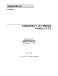
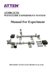
Documentation Standards – Document Control Revision No.: 15 Revision Date: 02/05/2015 Operation and Maintenance User Manual Models 400, 800, 1800, 3000 Bolttech-Mannings Corporate Headquarters 501 Mosside Blvd. North Versailles, PA 15137 www.bolttechmannings.com Page 1 of 25 Documentation Standards – Document Control Revision No.: 15 INDEX Revision Date: 02/05/2015 PAGE 1. Safety Information .……………………………………………...... 2. Introduction .………………………………………………………… 3. General Tool Layout ...……………………………………….…… .3.1 Basic Tool Configuration..…………….…..….………… . 3.2 Control Unit Layout ………………………………………. 4. Operating Instructions …………………………………………… 5. Routine Care and Maintenance ………………………………... 6. Control Unit Breakdown and Parts List………………………. 7. Troubleshooting …………………………………………………….. 8. PCB Battery Replacement……………………………………… 3 4 5 5 5 6-7 8 9 10 22-24 Page 2 of 25 Documentation Standards – Document Control Revision No.: 15 Revision Date: 02/05/2015 SAFETY INFORMATION Bolttech Mannings has designed this tool to be safe, ergonomic, and functional. Use of proper protective safety gear such as protective clothing, gloves, and safety glasses is recommended while using this tool. FAILURE TO FOLLOW THESE RECOMMENDATIONS COULD RESULT IN SERIOUS BODILY INJURY. The reaction arm will turn until it hits a stationary reaction point, typically an adjacent nut or housing structure. The reaction arm must be secure and stationary. KEEP ALL HANDS, FEET, AND CLOTHING AWAY FROM THE REACTION ARM – SERIOUS CRUSHING INJURIES CAN OCCUR. This tool should only be used with impact sockets. Page 3 of 25 Documentation Standards – Document Control Revision No.: 15 Revision Date: 02/05/2015 Introduction It is important to follow all guidelines laid out in this manual. Failure to do so can result in injury, voiding the warranty, and damage to the tool and or surrounding equipment. Each tool is accompanied by a certified calibration report. Refer to the report to determine the air pressure setting for the required torque. Due to variances in things such as compressed air supplies, joint characteristics and other application related variables, deviations from the calibration report may occur. Any modification to the reaction arm can affect torque output. The reaction arm supplied with the tool is designed to fit most industrial applications: ANSI B16.5, API, DIN, and British Flanges. Your tool can be fitted with a custom reaction arm for specific applications; however deviations from the standard reaction arm will affect torque output. Increasing dimension X will result in minimal torque deviation from the torque certificate supplied with the tool. This is shown in the cross hatched Area 1. Decreasing dimension X will result in minimal deviation from the torque certificate, however it will increase the amount of side-load exerted on the tool which can result in premature failure of the output drive. Increasing dimension Y will result in a decrease in torque from the torque certification supplied with the tool. This is shown in the cross hatched Area 2. Decreasing dimension Y will result in an increase in torque from the torque certification supplied with the tool. Where it is necessary to use an extension drive between the output square drive of the tool and the socket, you must provide a balanced reaction. A double sided reaction arm with both sides taking equal load serves this purpose. To ensure proper performance it is recommended to have Bolttech-Mannings design, manufacture and calibrate the custom reaction arm to fit your needs. Page 4 of 25 Documentation Standards – Document Control Revision No.: 15 Revision Date: 02/05/2015 General Tool Layout 3.1 Basic Tool Configuration 3.2 Basic Control Unit Layout Cage Air Inlet Air Pressure Regulator Knob Air Tool Oil Fill Cap Air Pressure Gauge Air Outlet Page 5 of 25 Documentation Standards – Document Control Revision No.: 15 Revision Date: 02/05/2015 Operating Instructions 1. Connect the control unit air inlet to a ½” dia. Air supply hose. NOTE: An air source of at least 45 CFM @ 90 psi MAX pressure is required. Failure to provide at least 45 CFM can result in deviations from the calibration report. 2. Using the torque certification supplied, set the regulator to the desired pressure without depressing the trigger on the pneumatic wrench. 3. This model is supplied with a toggle trigger. The direction (Tighten or Loosen) is controlled by which direction the trigger is depressed. Refer to the diagram below for which direction to change the rotation of the drive. 4. The final air pressure must be set after the tool has stalled on the first bolt with the trigger depressed. The stall point is reached when there is no longer any movement of the nut and there is a constant flow of air through the motor. After setting the final air pressure, the regulator can be locked by depressing the knob until it clicks, this will ensure the pressure remains at the set point for the required torque value. NOTE: Refer to the certificate of calibration for the particular model and Serial number of the tool. Verify that the test date is within the previous 12 months. Exceeding maximum torque value will result in tool failure and void tool warranty. Page 6 of 25 Documentation Standards – Document Control Revision No.: 15 Revision Date: 02/05/2015 5. For tightening, the stall point and torque is achieved by depressing the trigger (1) times after the nut has stopped rotating while the pneumatic torque tool is on the nut of the application. Some models may be supplied with a digital readout. The digital readout is used to display the air pressure and the torque being applied to the drive of the tool. To activate the digital readout, push the power button once. The display should turn on. At this point you will get to choose whether you want to see (PSI/ft-lbs) or (bar/N-m). To switch between the two, the button must be pushed and held for two seconds. The light will switch to the other side. To switch between PSI and ft-lbs, or bar and N-m, push the button once while the display is on. NOTE: After pushing the power button, the display will remain ON for 10 seconds. If you push the button with-in 10 seconds it will stay on for an additional 10 seconds. The digital readout is factory programmed during tool calibration using the USB interface. Page 7 of 25 Documentation Standards – Document Control Revision No.: 15 Revision Date: 02/05/2015 Routine Care and Maintenance The filter lubricator reservoir must be kept filled with air tool oil. This is accomplished by removing the air tool oil fill cap shown on page 4. Failure to keep the reservoir filled will result in permanent damage to the Tool and void factory warranty. The Auto-Oiler is factory pre-set. ANY adjustment will void warranty. The oiler is factory pre-set for (1) drop of oil every 3-5 seconds while running the tool wide open at 90 psi. Recommended Oil: Conoco Turbine Oil 32 or Equal Regulator filter is located after the air inlet and is 20 microns which should be replaced regularly. The first reservoir is for the collection of water removed from the inlet air. If the reservoir becomes filled with water, it can be expelled by loosening of the drain plug on the bottom of the reservoir. Caution: Reservoir is pressurized when connected to the air line. The drain plug should be opened slowly to avoid spray. Your tool needs to be calibrated on a yearly basis as a minimum to ensure correct torque values are being generated. Contact your Bolttech-Mannings representative to schedule a calibration service. Note: Any disassembling of the Multiplier OR Motor Assembly other than to replace the removable drive will void warranty. Page 8 of 25 Documentation Standards – Document Control Revision No.: 15 Revision Date: 02/05/2015 Control Unit Breakdown and Parts List Pressure Gauge Splitter Fitting Chicago Fitting Air Outlet Fitting Filter Regulator Lubricator (FLR) Unit Pop Off Valve Hose Strap Hose Strain Relief Strap clip Male Hose Fitting Female Hose Fitting Control Unit Part Number Quantity Filter Regulator Lubricator (FLR) CU2N 1 Chicago Fitting CU3N 1 Hose CU4N 1 Female Hose Fitting CU5N 1 Male Hose Fitting CU6N 1 Spacer Fitting CU7N 1 Pressure Gauge 160-250-NGFN 1 Splitter Fitting CU9N 1 Air Outlet Fitting CU10N 1 Pop-off Valve CU11N 1 Cage CU1N 1 Strap CU14N 1 Strap Clip CU15N 2 Hose Strain Relief CU17N 2 Page 9 of 25 Documentation Standards – Document Control Revision No.: 15 Revision Date: 02/05/2015 Troubleshooting 1. Air Supply, if the control unit is not getting at least 45 CFM the tool will not produce optimal torque values. Be aware that multiple feeds on a compressor will cause a drain on its volume output. 2. Back-nut secure, if the back nut turns then you will not obtain optimal torque values. The use of a back up wrench on the back nut will solve this. 3. Chase pattern, if the nuts are not being torqued in a viable chase pattern, uneven loading will occur effecting the torque values. 4. Socket size, minimizing the length of the socket used ensures more torque is being delivered to the nut. 5. Nut is seated, to achieve correct preload the nut must come to a complete stop during the torque process. 6. If the water reservoir becomes full, it can affect tool operation. Periodic draining of the water reservoir may be necessary. See routine care and maintenance. Digital readout only: 7. If the digital readout should stop working, you may replace the batteries located under the rear housing cap. The suggested batteries are (AAA) Energizer Lithium Ion. However, any (AAA) battery will work. 2 Batteries are required. If the device still does not work, it must be repaired by a Bolttech-Mannings service technician. Page 10 of 25 Documentation Standards – Document Control Revision No.: 15 Revision Date: 02/05/2015 AT400 Page 11 of 25 Documentation Standards – Document Control Revision No.: 15 Revision Date: 02/05/2015 AT400 Page 12 of 25 Documentation Standards – Document Control Revision No.: 15 Revision Date: 02/05/2015 AT800 Page 13 of 25 Documentation Standards – Document Control Revision No.: 15 Revision Date: 02/05/2015 AT800 Page 14 of 25 Documentation Standards – Document Control Revision No.: 15 Revision Date: 02/05/2015 AT1800 Page 15 of 25 Documentation Standards – Document Control Revision No.: 15 Revision Date: 02/05/2015 AT1800 Page 16 of 25 Documentation Standards – Document Control Revision No.: 15 Revision Date: 02/05/2015 AT3000 Page 17 of 25 Documentation Standards – Document Control Revision No.: 15 Revision Date: 02/05/2015 AT3000 Page 18 of 25 Documentation Standards – Document Control Revision No.: 15 ITEM NO. BOLTTECH‐MANNINGS PART NUMBER 1 2 3 4 6 7 8 9 10 11 12 13 14 15 16 17 18 19 20 21 23 24 25 26 27 28 29 30 31 32 33 34 35 36 37 38 39 40 41 42 43 44 45 46 ATM-2-ASSY ATM-4 ATM-5 AT-INNER-RACE ATM-HSG-BLK ATM-HSG-BLK ATM-16 ATM-17 AC300 91292A114 ATM-26 AM28 98381A439 90145A475 022-2012BB6-KIT 9528K12 ATM-19N MFS-01 92311A102 ATM-34 ATM-29 ATM-30 ATM-31 ATM-24 2418T112 92095A188 91292A113 92855A510 ATM-35 ATM-27 93070A120 AT-REAR-DECALN LOCTITE 7471 LOCTITE 420 LOCTITE 222 LOCTITE 242 LOCTITE INSTANT GASKET 5463K731 ATM-36 12841-BLK 91732A647 AT-DR 91239A224 93786A100 Revision Date: 02/05/2015 ATM‐1 QTY. ATM‐1‐PCB QTY. 1 1 1 1 1 1 1 1 1 1 1 1 1 10 2 1 1 1 1 55 1 1 1 1 1 1 2 3 2 2 3 4 1 1 5 1 N/A N/A N/A N/A N/A 1 1 1 11 0 2 2 1 1 1 10 2 1 1 1 1 55 N/A 1 1 1 1 1 2 3 2 2 5 4 1 1 5 N/A N/A N/A N/A N/A N/A N/A 1 1 11 1 2 2 DESCRIPTION WELDED PLENUM ASSEMBLY TRIGGER TRIGGER EXTENSION INNER BALL BEARING RACE LEFT MOTOR HOUSING ASSEMBLY RIGHT MOTOR HOUSING ASSEMBLY THREADED HOUSING CAP VALVE SPRING RETAINER MOTOR CELL M3 X 0.50 X 12MM LONG SOCKET HEAD CAP SCREW M5 X 0.80 X 8MM LONG SOCKET SHOULDER SCREW AIR INLET FITTING 3/32" DIA. X 9/16" LONG DOWEL PIN 1/8" DIA. X 1.000" LONG DOWEL PIN SPOOL VALVE ASSEMBLY 5/32" STEEL BALL HOUSING BACK FOR NO PCB 3/8" NPT MULTI FLEX SWIVEL 4-40 X 3/32" SOCKET SET SCREW PLENUM SEAL UPPER FRONT MUFFLER UPPER REAR MUFFLER LOWER MUFFLER SPOOL VALVE WASHER BUNA-N O-RING M4 X 0.70 X 6MM BUTTON HEAD CAP SCREW M3 X 0.50 X 10MM LONG SOCKET HEAD CAP SCREW M5 X 0.80 X 10 MM LONG LOW SOCKET HEAD CAP SCREW 3/8" I.D. 300PSI MAX FLEX TUBE FEMALE BARB FITTING M5 X 0.80 X 8MM LONG LOW SOCKET HEAD CAP SCREW LOGO STICKER PRIMER SUPER GLUE PINK THREAD SEALER BLUE THREAD SEALER BLACK GASKET SEALANT 1/16" I.D. HOSE BARB FITTING PLUG 1/8" O.D. X 1/16" I.D. ANTISTATIC WHITE TUBING 1/16" I.D. HOSE FITTING M3 X 4.5 MM LONG HELICOIL DIGITAL READ OUT KIT M5 X 0.8 X 10MM BUTTON HEAD CAP SCREW M5 PRESSURE SEALING WASHER See Page 21 for ATM-1-PCB Parts Call-out and Parts List Page 19 of 25 Documentation Standards – Document Control Revision No.: 15 Revision Date: 02/05/2015 Page 20 of 25 Documentation Standards – Document Control Revision No.: 15 Revision Date: 02/05/2015 Page 21 of 25 Documentation Standards – Document Control Revision No.: 15 Revision Date: 02/05/2015 PCB Battery Replacement Procedure Tool needed: 2.5mm Hex T-Handle Wrench Recommended batteries: (2) AAA Energizer Advanced Lithium Use T-handle to remove the (3) screws that hold the rear cover on the tool. Carefully remove cover from Page 22 of 25 Documentation Standards – Document Control Revision No.: 15 Revision Date: 02/05/2015 Carefully remove batteries with your fingers. (Do not use any conductive items to pry the batteries out) Insert new batteries in the proper direction shown on the printed circuit board. Page 23 of 25 Documentation Standards – Document Control Revision No.: 15 Revision Date: 02/05/2015 Place cover on the Tighten cap screws in a cross pattern. Tighten to 17 in-lbs of torque. Page 24 of 25 Documentation Standards – Document Control Revision No.: 15 Revision Date: 02/05/2015 Revision History Rev No. Date 11 7/25/2012 12 7/31/2013 13 14 15 11/27/2013 04/01/2014 2/5/2015 Description of Revision Updated to new format. Added to Routine Care and Maintenance: The first reservoir is for collection… Motor Housings to a qty. of 1 as a set. Fixed plenum seal part number: ATM‐32 to ATM‐34. Updated Parts Lists to match Discovery Added PCB battery replacement procedure. Implemented Handle Conversion to bolts Revised Page(s) Approved By: All B. Gruber 19 Matt R. 12,14,16,18,19 All 19‐20 D. Mierski Devon D. Mierski Page 25 of 25