1
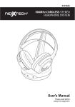
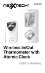
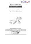
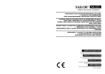
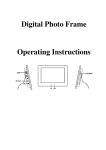
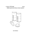
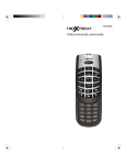
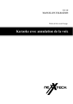
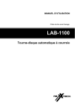
4919538
User’s Manual
WIRELESS 2.5” COLOR
TFT LCD
BABY MONITORING SYSTEM
- Portable 2.5” Color TFT LCD with Receiver
- Wireless Color Camera
PLEASE READ CAREFULLY AND SAVE
This manual contains important information about this product’s operation.
If you are installing this product for use by others you must leave this
manual (or a copy) with the end user.
Model No.: CCD-420
Wireless 2.5” Color TFT LCD Monitoring System
Contents
Safety and Hazard Notices ..................................................................................................................1
FCC/CE Warning ..............................................................................................................................................2
Installing the Camera .................................................................................................................................3
Installing and Connecting the Devices .................................................................................3
Connecting the Camera ..........................................................................................................................4
Installing the Receiver ..............................................................................................................................4
Connecting the Receiver ........................................................................................................................4
System Installation ..................................................................................................................................5 - 6
Maintenance .........................................................................................................................................................6
Technical Data ....................................................................................................................................................7
Disposal ....................................................................................................................................................................8
Troubleshooting ...............................................................................................................................................8
Warranty ....................................................................................................................................................................9
Parts Included with this System
1x
1x
1x
1x
1x
2.4GHz Wireless Color Camera
2.4GHz Wireless Receiver
A/V Cable
7.5V AC/DC Adaptor for the camera
5V AC/DC Adaptor for the receiver
Safety and Hazard Notices
Damages caused with non-compliance of this operating manual lead to the
expiration of this warranty! We will not assume any liability for subsequent
damages! We will not assume any liability for any damages to items or
persons caused by improper handling or non-compliance with the safety
notices! Any warranty claim will be null and void in such cases.
* This product has left the factory in perfectly safe condition. In order to maintain
this status and ensure a safe operation, the user must observe the safety notice
and warnings (“ATTENTION” and “NOTICE”) contained in this operating manual.
Important Safety Instructions
CAUTION
RISK OF ELECTRIC SHOCK
DO NOT OPEN
CAUTION- These servicing instructions are for use by
qualified personnel only. To reduce the risk of
elecric shock, do not perform any servicing
other than that contained in the operating
instructions unless you are qualified to do so.
This symbol is intended to alert
you to the presence of uninsulated
dangerous voltage within the
product’s enclosure that might be
of sufficient magnitude to constitute
a risk of electric shock. Do not
open the product’s case.
This symbol is intended to
inform you that important
operating and maintenance
instructions are included in the
literature accompanying this
product.
WARNING: To reduce the risk of fire or electric shock, do not expose this product to rain or moisture.
PLEASE READ CAREFULLY AND SAVE
This manual contains important information about this product’s operation. If you are installing
this product for use by others you must leave this manual (or a copy) with the end user.
*
Use only a (110V - 240 Volt / 50 hz -or 60 Hz) adapter for the product to plug
into a standard wall outlet receptacle. Never attempt to operate the product
with a different voltage.
*
Ensure all electrical and/or cable connections between the Monitoring
System’s camera and receiver are connected correctly and conform to the
operating instructions.
*
In commercial institutions, make sure you observe the accidental prevention
regulations of the commercial trade organization for electrical installations.
*
In schools, training facilities, hobby and self help workshops, qualified
personnel need to supervise the installation of this product.
*
Observe the safety notices of any other products connected to this system.
*
Contact an expert when you have any doubts about the mode of operation or
safety issues when connecting this system.
*
When opening the battery covers, or removing any parts from the product(s)
you may expose live wires/parts. Prior to aligning, cleaning, servicing, repair
1
work or exchanging parts or modules, you must separate the product(s)
from any power sources first. Only an expert familiar with the risks and any
pertinent regulations should maintain/repair the product(s).
*
Never plug-in or unplug the products power cord or battery case section with
wet hands.
*
Never tug on any cords attached to the product. Hold the plug when
unplugging from the wall outlet.
*
Unplug the product(s) from wall outlet(s) during thunderstorms.
*
Make sure that all cables do not get squashed or damaged by sharp edges
when installing the product(s).
*
Never replace a damaged power cord yourself! Take the product to a qualified
electrician for repair.
FCC/CE Warning
The FCC Wants You to Know
This equipment has been tested and found to comply with the limits for a Class
B digital device, pursuant to Part 15 of the FCC Rules and CE I-ETS 300 440.
These limits are designed to provide reasonable protection against harmful
interference in a residential installation. This equipment generates, uses and can
radiate radio frequency energy and, if not installed and used in accordance with
the instructions, may cause harmful interference to radio communications.
However, there is no guarantee that interference will not occur in a particular
installation. If this equipment does cause harmful interference to radio or
television reception, which can be determined by turning the equipment off and
on, the user is encouraged to try to correct the interference by one or more of the
following measures:
• Reorient or relocate the receiving antenna.
• Increase the separation between the equipment and receiver.
• Connect the equipment into an outlet on a circuit different from that to which
the receiver is connected.
• Contact your local electronic store for help.
FCC Information
This device complies with Part 15 of the FCC Rules. Operation is subject to the
following two conditions:
(1) this device may not cause harmful interference, and
(2) this device must accept any interference received, including interference
that may cause undesired operation.
Warning: Changes or modifications to this unit not expressly approved by the party
responsible for compliance could void the user’s authority to operate the equipment.
2
Installing the Camera
ATTENTION!
Prior to drilling and inserting the screws, make sure that there are no electric cables pipes,
etc. in the wall that could be damaged.
1
2
3
CH 1 2 3 4
PWR. BAT.LO
9
7
5
10
DC IN 7 .5 V /5 00mA
4
8
POWER
ON/OFF
6
1
2
3
4
5
6
CAMERA
ON/OFF
11
Antenna
Low battery indicator
Power indicator
Eye ball camera lens
Power ON/OFF switch
Microphone
7 IR LED
8 Camera ON/OFF switch
(camera kit/baby monitor)
9 Channel switch
10 DC Power
11 Power adaptor plug with low voltage switch
Installing and Connecting the Devices
Select a suitable installation site from which you can monitor the desired area.
A suitable installation site has the following features:
•
•
dry
good air circulation
•
•
as dust-free as possible
a wall outlet in close vicinity
•
few vibrations
Select an installation site that is not screened off by reinforced concrete walls, mirrors, metal
shelves, etc.
There should not be any appliances with strong electric fields close to the sender or the receiver.
The above points could severely impair radio transmission and reduce the units field 16’ (5m) range.
Fastening the wall bracket
• Look for a suitable place
for mounting
(with a socket near-by).
20
20
20
20
wall mount slot
CH 1 2 3 4
DC IN 7 .5 V /5 00mA
attach stand to
mounting surface
battery
compartment
• Screw the wall bracket with the
supplied screws to a suitable
wall or platform, using dowels
if relevant.
• Align the camera and screw the
corrugated plastic sleeve tight.
• See the System Installation
section for battery instructions.
3
Connecting the Camera
Connect the small voltage plug of the power unit to the voltage supply jack of the
camera. Pay attention to the correct output voltage of 7.5V DC!
• Insert the plug-in power unit into a suitable wall outlet.
• The camera is now ready for use.
Installing the Receiver
Install the monitor approx. 3’ (1 m) above ground (for better reception). A wall
outlet should be near by.
ATTENTION!
Place the monitor on a sturdy, stable surface. If the surface is delicate, use a suitable
underlay to protect it from damage.
VOL.
2
BRIGHT
7
1
CH SELECT
8
A/V OUT
4
9
DC IN POWER
OFF
5
CH1 CH2 CH3 CH4 BAT.LOW
POWER
ON
SCREEN
OFF
3
11
6
POWER ON
SCREEN ON
POWER OFF
1
2
3
4
5
10
VOL. Control
Brightness Control
CH Select
A/V Output
LCD Power ON/OFF
6 DC Power
7 Antenna
8 Channel LED
9 BAT.LOW LED
10 Power adaptor plug with
low voltage switch
11 A/V Cable
• Connect the AV cable as shown to a suitable monitor
or TV system with an AV cinch input and the receiver
(white/red plug = audio (tone in mono), yellow plug =
video.
• Connect the small voltage plug of the power unit to the
voltage supply jack of the receiver. Pay attention to the
correct output voltage of 5V DC!
POWER
ON
• Insert the plug-in power unit into a suitable wall outlet.
• The receiver is now ready for use.
DC IN POWER
OFF
SCREEN
OFF
A/V OUT
CH SELECT
BRIGHT
VOL.
Connecting the Receiver
4
• See the System Installation section for battery
instructions.
System Installation
When installing the camera, check the reception of the monitor before final
installation. Have someone hold the camera in the area to be monitored. Have
another person move the monitor to a variety of locations throughout the house
to check the reception. If interference or any other problems occur, refer to the
“Troubleshooting” section of this manual.
To install the system follow these steps:
Monitor:
1. Plug the 5V AC/DC adapter cord into the DC output jack on the side of the
monitor.
2. Plug the adapter into a standard (110V - 240V) AC wall outlet. Press the power
button to turn on the monitor.
3. A/V outputs on the LCD monitor can be connected to the A/V input on a TV set
for the large screen display, or to the A/V inputs on a VCR for recording.
4. You can use the AC/DC adapter for long time use or four “AAA” batteries for
mobile use. The lifetime of four “AAA” batteries in use is 45 minutes.
Camera:
1. Plug the 7.5V AC/DC adapter cord into the DC input jack on the back of the
camera.
2. Plug the adapter into a standard (110V - 240V) AC wall outlet.
3. You can use the AC/DC adapter for long time use or two “AA” batteries for
mobile use. The lifetime of two “AA” batteries in use is 1.5 hr w/o IR function
and 1 hr with IR function.
System Setup:
12
CH
1. Select a channel (Channels 1-4) to be
used on both the camera and the receiver.
NOTE: Make sure both the camera and
the receiver are set to the same channel
(1, 2, 3, or 4) and that the camera
Camera
Receiver Set
Set to
to Channel 1
is turned to the on position.
2. Select the desired channel by gently pushing Channel 1
the dip switch to the same channel number
on both the camera and the receiver.
For example, to set both the camera and receiver on Channel 1:
Push the Channel 1 dip-switch located on the side of the camera and
the receiver to the same number.
3. For the baby monitoring feature, place the camera’s “ON/OFF” switch to the
“OFF” position on the transmitter unit.
NOTE: Make sure the camera and receiver are set to the same channel
number first.
3 4
CH1 CH2 CH3 CH4 BAT.LOW
5
System Installation (con’t)
Additional Notice - When installing the camera, check the reception of the
receiver before the final installation. Have someone hold the camera in the area
of to be monitored and another person to check the reception on your TV or
monitor. If interference or other problems occur, refer to the “Troubleshooting”
section of this manual.
Maintenance
This system is maintenance free - do not open the unit(s)! Your guarantee will
become void if you do. Before cleaning, unplug the product(s) from all voltage
sources and clean the outside with a soft dry cloth or brush.
ATTENTION!
Do not use any carbolic cleaning agents, petrol, alcohol or similar chemicals which can
damage the surfaces of these unit. Do not use any sharp edged tools, screwdrivers, metal
brushes or similar items to clean these units.
6
Technical Data
Camera
Receiver
Operating Voltage
7.5V DC
(plug-in power unit) battery
operation 2 x “AA” Alkaline
5V DC
(plug-in power unit) battery
operation 4 x “AAA” Alkaline
Current Consumption
200 mA
600 mA
Transmitting Frequency
2.4-GHz
2.4-Ghz
Modulation
FM
Channels
4
Light Sensitivity
0 Lux
4
Video Output Level
1Vp-p / 75 Ohm
Audio Output Level, mono
1Vp-p / 600 Ohm
Audio/Video
Connection Jacks
3.5mm jack > cinch
Picture Sensor
1/3” CMOS color 628x562
pixel (PAL) or 510x492
(NTSC)
2.5” TFT
Resolution
330 TV lines (horizontal)
480x234
Microphone
mono
Picture
Color
Range
100m / 300 ft (line of sight)
100m / 300 ft (line of sight)
Operating Temperature
14 to 122˚F / -10˚C to +50˚C
14 to 122˚F / -10˚C to +50˚C
Mass approx.
(without tripod)
157g
160g
Dimensions
without Aerial
2.95 x 1.3 x 4.8 (inches)
75x33x122mm (LxWxH)
2.95 x 1.3 x 4.8 (inches)
75x33x130 (LxWxH)
Operating Voltage
110-240V / 60 or 50 Hz
110 - 240V - 60 or 50Hz
Output Voltage
7.5V DC / 500mA
5V DC / 1000mA
Plug-in power units
7
Disposal
If the camera system no longer functions properly and cannot be repaired, it must
be disposed of according to valid statutory regulations for your area.
Disposing of spent batteries and toxic materials
All batteries, accumulators and toxic substances must be recycled
properly. They are not to be disposed of in regular household waste but to
a collection point in your community area. Abbreviations for the respective
heavy metals can be found on the side of the product(s) and are shown as:
Cd = cadmium, Hg = mercury and Pb = lead.
Troubleshooting
You can easily fix any problems or malfunctions.
Observe the safety notices under all circumstances!
Error
Possible Cause
No image and no sound
• Camera or monitor not supplied with electricity
• Power source is plugged in incorrectly or the
batteries are drained
• Distance between camera and receiver is too large.
• The same channels are not set on the camera and
the receiver
The image/sound is distorted
• System’s range between camera and receiver was
exceeded.
• There is a strong interference source nearby.
• Distance between units is too short and may over
steer the receiver. Increase the distance.
• The supply voltage is too low (change batteries).
Flickering/running image
• Strong spotlight in the cover range of the camera
• Adjust the vertical hold.
Normal sound, but image is too
light or too dark.
• The monitoring range of the camera is not lit properly
• Surveillance monitor is adjusted wrong.
(readjust contrast or brightness).
• Strong spotlight in the cover range of the camera.
White image only on the monitor
• The supply voltage is too low (change batteries or
power pack operation).
• The surveillance monitor is not correctly adjusted
(brightness controller).
ATTENTION!
All other repairs not described above should only be performed by an authorised
Repair Centre.
8
•
Defacing the serial number, or using your Product
for commercial or institutional purposes, voids this
warranty.
Who is Providing This Warranty?
Are There Other Warranties?
•
•
Orbyx Electronics, LLC (“Orbyx”), as the distributor of
this NexxtechTM product (your “Product”).
What Does This Warranty Cover?
•
This warranty covers defects in materials or workmanship in your Product under normal use and conditions.
•
What is the Period of Coverage?
•
This warranty covers your Product for 90 days from
the original purchase date.
Who Is Covered?
•
This warranty covers the original consumer purchaser.
Coverage terminates if you sell or otherwise transfer
your Product.
There are no express warranties other than those
expressed herein. Neither the sales personnel nor
any other person is authorized to make any other
warranties
or to extend the duration of any warranties.
ANY IMPLIED WARRANTIES, INCLUDING ANY
IMPLIED WARRANTY OF MERCHANTABILITY
(AN UNWRITTEN WARRANTY THAT A PRODUCT
IS FIT FOR ORDINARY USE), ARE LIMITED TO
90 DAYS. Some states do not allow limitations on
how long an implied warranty lasts, so the above
limitation may not apply to you.
How Does State Law Apply?
•
This warranty gives you specific legal rights, and you
may also have other rights which vary from state to
state.
What Will We Do To Correct Problems?
•
We will repair your Product or replace your Product
with a new or reconditioned equivalent product, at our
option.
How Do You Get Service?
ORBYX ELECTRONICS WARRANTY
•
ORBYX Electronics warrants that this product will be free
from defects in materials and workmanship for a period
of ninety (90) days from the date of purchase. Within this
period, simply take the product and your proof of purchase
to any ORBYX Electronics store or dealer and the product
will be repaired without charge for parts and labour. ORBYX
Electronics reserves the right to charge for transportation.
Any product which has been subject to misuse or accidental
damage is excluded from this warranty.
This warranty is only applicable to a product purchased
through ORBYX Electronics’ company owned stores and
dealers and to a product that is presented for repair in a
country where ORBYX Electronics offers the product for
sale. While this warranty does not confer any legal rights
other than those set out above, you may have additional
statutory rights which will vary under the laws of the various
countries, states, province and other governmental entities
in which ORBYX Electronics operates. This warranty is subject to all statutory rights you may have in the country of
purchase.
•
•
Call Orbyx TOLL FREE at 1-866-363-3059 for
instructions for obtaining warranty service from Orbyx’s
authorized service providers.
Or, return your Product directly to the retail store from
which you purchased the Product.
When you obtain service for your Product, you must
provide a purchase receipt (or other proof of the original purchase date) and a description of the defect(s).
What Does This Warranty Not Cover?
•
•
•
•
•
•
This warranty DOES NOT COVER:
damage due to misuse, abuse, alteration,
unauthorized repair, or accident
(such as improper electrical current);
damage due to “acts of God” (such as lightning) or
other contingencies beyond our control;
cosmetic damage;
externally generated static, signal reception or antenna
problems not caused by your Product; or batteries.
This warranty also DOES NOT COVER, and in no
case will we be liable for, any incidental damages
(such as transportation costs to and from an authorized service provider, or loss of time) or consequential
damages (such as costs of repairing or replacing other
property which is damaged, including tapes, discs,
speakers not included with your Product or other
accessories, or external electrical systems) resulting
from the use of your Product. Some states do not
allow the exclusion or limitation of incidental or consequential damages, so the above limitation or exclusion
may not apply to you.
Distributed exclusively in the U.S. by
Orbyx Electronics, LLC
501 South Cheryl Lane,
Walnut, CA 91789
Imported in Canada for/Importé au Canada pour
Orbyx Electronics,
Concord, Canada, L4K 4M3
Manufactured in China
For product support please contact www.orbyxelectronics.com or 1-866-363-3059
Limited Warranty/Garantie Limitée
U.S.A & Canada
© 2005 ORBYX Electronics. All Rights Reserved.
9