1
Lisa
Service Manual
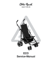
Service Instructions for LISA Rehab Buggy/Stroller
(Models from 2005, HR3213.../HR3214...)
Contents
1
2
Page
General Information
1.1
Preface ................................................................................................................................... 2
1.2
Warning Symbols ................................................................................................................... 2
1.3
Information for Service Staff.................................................................................................. 2
1.4
Support .................................................................................................................................. 3
Safety Instructions............................................................................................................................ 3
2.1
Warning Symbols ................................................................................................................... 3
2.2
General Safety Instructions ................................................................................................... 3
3
Maintenance Plan and Required Tools............................................................................................. 4
4
Settings / Retrofit / Replacement .................................................................................................... 6
4.1
Anterior Frame ....................................................................................................................... 6
4.2
Posterior Frame ..................................................................................................................... 7
4.3
Folding Scissor Construction ................................................................................................. 9
4.4
Back ..................................................................................................................................... 10
4.5
Back Adjustment Mechanism .............................................................................................. 13
4.6
Seat Base............................................................................................................................. 14
4.7
Footrest ................................................................................................................................ 15
4.8
Wheel Lock / Tip-assist........................................................................................................ 17
4.9
Front Wheel .......................................................................................................................... 18
4.10 Rear Wheel ........................................................................................................................... 20
4.11 Abductor............................................................................................................................... 21
4.12 Armrest................................................................................................................................. 22
4.13 Grabrail ................................................................................................................................ 23
4.14 Caster Swivel Lock............................................................................................................... 24
1
1 General Information
1.1 Preface
Regular maintenance is important. It increases safety and prolongs the service life of the product.
All rehab products should be inspected and serviced once a year. If the product is used frequently, or if it is
used by growing children or patients with changing clinical conditions, it should be readjusted and serviced
every 6 months. The service and maintenance described in this manual should be performed by skilled
specialists only and not by the user. This service and maintenance manual refers to the spare parts catalogs
and instructions for use manuals for the products described here. For this reason, it is important to use these
documents together. Use the maintenance plans (see section 3) as a template for making copies. Retain
completed maintenance plans and provide the customer with a copy.
1.2 Warning Symbols
Danger!
Warning messages regarding possible risks of accident or injury.
Attention!
Warning messages regarding possible technical damages.
Note!
Information for service staff.
Note!
Please read the Instructions for Use first!
1.3 Information for Service Staff
• Use only original spare parts for all service and maintenance to maintain the warranty.
• Are you familiar with the functions of the product? If not, please read the Instructions
for Use first! If you do not have them, you can order the Instructions for Use from Otto
Bock or download them from our homepage at www.ottobock.de (German version) or
www.ottobock.com (other languages).
• Clean and disinfect the product before starting inspection. Please observe the maintenance
and cleaning instructions contained in the Instructions for Use!
• These service instructions will explain, among other things, how to dismantle individual
components. For reassembly, please proceed in reverse order. If other or additional steps are
required for reassembly, we will point out them separately in the corresponding section.
2
1.4 Technical Support
For technical questions, please contact our Customer Service (phone no.: ++49-5527-848-1590).
Lisa rehab buggy/stroller
Instructions for use
647H140
Spare parts catalog
646K79
2 Safety Instructions
Observe the following guidelines for maintenance or repair work:
Danger!
Always wear adequate protective clothing (e.g. gloves, safety glasses, etc.) and use appropriate
tools (refer to page 4)!
Danger!
You may get injured if the product tips over or falls off a work surface (e.g. workbench)!
Secure the product to prevent it from tipping over or falling off any work surfaces!
Danger!
Unsecured screw connections can become loose while using the product.
This can lead to accidents, resulting in a risk of injury to the person being transported in the
product!
Always secure screws and nuts. If you have to undo such screw fastenings, replace self-locking
nuts exclusively with new ones. To secure the screws, use a medium-strength liquid thread lock
substance (such as Loctite 241 or Euro Lock A24.20).
Danger!
Bald tires can lead to accidents.
This results in a risk of injury to the person being transported in the product!
Wheels with EVA foam tires must be replaced if the material shows signs of cracking or damage,
or when the tread becomes worn down to such an extent that there is only 5 mm of radius left on
the outer edges of the tire.
Replace the casing of pneumatic tires if it is bald or shows signs of cracking or other damage.
Danger!
Always observe the following guidelines:
• Times needed for adhesives to set
• Torque indications for screw connections!
Non-compliance with these instructions can lead to malfunctioning of the product and accidents.
In such cases, there is a risk of injury to the person being transported in the product!
3
3 Maintenance Plan and Required Tools
The following list shows you the tools and auxiliaries mentioned in the text.
Reversible ratchet handle wrench and
sockets, sizes 8 mm to 19 mm
Torque wrench,
measurement range 10 Nm to 50 Nm
Wrenches, sizes 8 mm to 19 mm
Allen wrenches, sizes 3 mm to 6 mm
Screw driver, blade width 2.5 mm
Phillips head screwdriver, size 2
Plastic hammer
Stanley knife with sickle hooked blade
and standard blade
Liquid thread lock "medium strength"
4
Maintenance Plan
for Regular Service
Item
Lisa
rehab buggy/stroller
Component (group)
Serial no.:
Customer:
Inspection (check list)
1.)
Function / setting
(refer to 647H140 Instructions for Use)
2.)
Inspected for
damages/deformations
3.)
Screw connections
inspected
LISA
4.1
Anterior frame
- Frame
4.2
Posterior frame
- Frame
- Rubber hand grips
4.3
Folding scissor construction
- Folding mechanism
4.4
Back
- Frame
- Folding mechanism
- Upholstery
4.5
Back adjustment mechanism
- Angle adjustment mechanism
4.6
Seat base
- Frame
- Folding mechanism
- Upholstery
- Depth setting
4.7
Footrest
- Frame
- Footplate
- Lower leg length
- Depth setting
4.8
Wheel lock / tip-assist
- Wheel locks
4.9
Front wheel
- Tires
- Air pressure (with pneumatic tires)
- Running behavior of the wheels
- Swiveling of the wheel forks
4.10
Rear wheel
- Tires
- Air pressure (with pneumatic tires)
- Running behavior of the wheels
Accessories
4.11
Abductor
- Fold-down mechanism
- Depth adjustment
- Cover
4.12
Armrest
- Flip-down mechanism
- Height setting
- Rubber hand grips
4.13
Grabrail
- Locking function by engaging tripod
springs
4.14
Caster swivel lock
- Locking function
Notes:
Do the settings of the rehab
buggy/stroller comply with the
user‘s requirements?
Maintenance performed by:
on:
5
4 Settings / Retrofit / Replacement
4.1 Anterior Frame
Replacing an Anterior Frame (right/left)
First place the unfolded rehab buggy/stroller on its
back.
Loosen and remove the screws (arrowed) from the
anterior frame.
Remove the front wheels and wheel forks as
described in section 4.8.
Pull the front wheel attachment out of the anterior
frame.
Open the footrest lock and pull the pivot bearing of
the respective side down from the anterior frame.
6
Loosen and remove the screw connections
(arrowed) on the slide and on the seat tube and
pull the anterior frame out of the loops of the lateral
upholstery.
Use new, self-locking screws and nuts.
4.2 Posterior Frame
Replacing one side of the Posterior Frame
(right/left)
Place the unfolded buggy/stroller on its side.
First loosen and remove the screw connections
between the frame side to be replaced and the...:
Loosen and remove the screw connection between
the back adjustment mechanism and the guiding slot
in the gusset plate.
Pay attention to the order of washers and bushings
for later reassembly.
- rear wheel (refer to section 4.10)
- wheel lock (refer to section 4.8)
- folding scissor construction (refer to section 4.3)
- backrest (refer to section 4.4)
Loosen and remove the screw connection (arrowed)
between the seat tube and the gusset plate of the
posterior frame.
Loosen and remove the screw connections
(arrowed) on the slide. Remove the inner half of the
slide and pull the posterior frame down out of the
loop of the lateral upholstery.
Use new, self-locking screws and nuts.
7
Replacing the Rubber Hand Grips
Carefully cut open the rubber hand grip using a
stanley knife and remove the old rubber hand grip.
Remove the residue of the old glue or rubber from
the tube.
Using a clean cloth and solvent, fully degrease the
end of the push handle tube.
Apply half of the adhesive into each of the rubber
hand grips using the spatula. Evenly distribute the
adhesive in the rubber hand grip up to a depth of
approx. 4-5 cm.
8
Open the two part adhesive sachet. Use the spatula
to squeeze out all the contents of the sachet into the
centre of the mixing card and mix the components
thoroughly (approx. 30 seconds).
Slide the rubber hand grip onto the push handle
rotating it through 180° as it is pushed on.
The push handle should not be used
for at least 24 hours so as to allow full
curing of the adhesive!
4.3 Folding Scissor Construction
Replacing the Folding Scissor Construction
Place the unfolded buggy/stroller in front of you.
First loosen and remove the lower screw
connections between the joint forks and the right and
left posterior frame.
Next loosen and remove the screw connections
between the tube ends of the folding scissor
construction and the upper joint forks and thread out
the loop of the lateral upholstery.
Loosen and remove the screw connection between
the joint fork and the slide.
9
4.4 Back
Replacing the Back
Undo the hook and loop closure on the back
upholstery and thread out the handle and cable
downwards.
Next loosen and remove the four screws on the left
and right side of the back upholstery and remove the
back upholstery.
Loosen and remove the screw connection between
the back adjustment mechanism and the guiding slot
in the gusset plate.
First remove the back cover. To do this, undo
the hook and loop straps on the folding scissor
construction and the snap fasteners on the back
tubes.
Pay attention to the order of washers and bushings
for later reassembly.
10
Loosen and remove the screw connection on either
side between the back tube and the gusset plate of
the posterior frame and remove the backrest.
Pay attention to the order of the washers, bushings
and the metal ring with plastic loop. Proceed in
reverse order for reassembly.
Use new, self-locking nuts.
Finally, disassemble the back adjustment mechanism
as described in section 4.5.
Replacing a Lateral Upholstery
An elastic cord holds the lateral upholstery taut. First
pull the plastic clip off the posterior frame tube and
thread out the elastic cord.
Replacing the Complete Upholstery
The complete upholstery consists of the seat
upholstery (refer to section 4.6), the back upholstery,
the lateral upholsteries and the back cover.
To replace the back cover and the back
upholstery, first proceed as described in "Replacing
the Back".
After unscrewing the back upholstery, pull the four
battens out of the back upholstery and insert them
into the new back upholstery.
The elastic cord runs below the backrest's screw
connection and through between the gusset plate
and the seat tube.
Pull out the elastic cord completely.
11
Pull the loop of the lateral upholstery up and off the
folding scissor construction, as described in section
4.3 and off the anterior frame, as described in
section 4.1.
Finally, remove the lateral upholstery by pulling it up
and over the posterior frame and push handle.
Readjusting the Tension of the Back
Upholstery
Replacing the Folding Levers
Release the tension on the backrest as shown in
the photo. Loosen the four lower screws of the back
upholstery. Undo the hook and loop closure of the
back upholstery and readjust the tension of the back
upholstery. Firmly re-tighten the four lower screws of
the back upholstery.
Make sure that the back upholstery is evenly taut on
both sides.
12
First disassemble the back upholstery and the back
adjustment cable (see section 4.5).
Loosen and remove the screw connection between
the folding levers and the back tubes and remove
the folding levers.
4.5 Back Adjustment Mechanism
Replacing the Back Adjustment Mechanism
First completely disassemble the back as described
in section 4.4. The back upholstery does not need
to be disassembled when replacing the back
adjustment mechanism.
Thread the cable out of the right and left key ring.
Thread the cable out of the back upholstery.
Unscrew the eye bolt out of the folding lever.
Loosen and remove the screw connections between
the back tube and the bracket and remove the back
adjustment mechanism.
13
4.6 Seat Base
Shifting / Replacing the Seat Base
Loosen and remove the screw connections
(arrowed) between the seat tubes and the anterior
frames, and the seat tubes and the gusset plates of
the posterior frames.
You can select two depths when
assembling the seat base.
Readjusting the Tension of the Seat
Upholstery
Loosen the four screw connections on the right side
of the seat base.
14
Replacing the Seat Upholstery and the Seat
Braces
Loosen and remove the four screw connections on
both the left and right seat tubes and remove the
seat upholstery and the seat braces.
Pay attention to the order of the washers and
bushings.
Undo the hook and loop closure and readjust the
tension of the seat upholstery.
Firmly re-tighten the screw connections.
4.7 Footrest
Replacing the Footrest
Place the unfolded rehab buggy/stroller on its back.
Remove the front wheel attachments as described in
section 4.1.
The casters and forks, however, do not need to be
disassembled.
Open the footrest lock as described in the
Instructions for Use.
Pull the pivot bearings with the attached footrest
halves down off the anterior frame.
Attention!
To ensure safe use of the product, make sure that the footrest has the same height setting on the
left and right side.
Setting the Lower Leg Length
Loosen the screw connections in the clamp pieces
and move the footrest tubes to the desired height.
The footrest tubes can be pulled down out of the
clamp pieces and can be replaced.
From a lower leg length of 34 cm the pivot bearing
must be set in the lower position.
Firmly re-tighten the screw connections.
Shifting / Replacing the Pivot Bearings
To replace the pivot bearings, please proceed as
described in "Replacing the Footrest".
For shifting the pivot bearings, observe the
instructions given in the Instructions for Use.
15
Shifting / Replacing the Footplate
Replacing the Footrest Tubes
Shifting / Replacing the Footrest Lock
Pull the lock bolt together with the compression
spring out of the footrest tube.
Open the footrest lock as described in the
Instructions for Use.
Loosen and remove the screw from the footrest tube
and pull the footplate off the footrest tube.
Using a small screwdriver, loosen the retaining ring
from the lock bolt and pull the turning bolt out of the
lock bolt.
16
Disassemble the fooplate and pull the footrest tubes
out of the pivot bearings' clamp pieces.
Remove the lamellar plugs from the tube ends. Pull
the threaded insert out of the right footrest tube and
use it in the new footrest tube.
Disassemble the footrest lock from the left footrest
tube and replace the footrest tube.
For the reassembly you can select two depths of the
footplate.
4.8 Wheel Lock / Tip-assist
Replacing the Wheel Lock
As a complete unit the wheel lock can be pulled
down out of the posterior frame tubes.
Shifting / Replacing the Tip-assist
To change the mounting side, loosen and remove
the corresponding screw connection on the opposite
side of the wheel lock and exchange the screw
connections with each other.
First disassemble the two rear wheels as described
in section 4.10.
Loosen and remove the tip-assist's screw
connection and remove the tip-assist from the frame.
Firmly re-tighten the screw connections.
17
4.9 Front Wheel
Danger!
To ensure safe use of the product, wheels with EVA foam tires must be replaced if the
material shows signs of cracking or damage, or when the tread becomes worn down to
such an extent that there is only 5 mm of radius left on the outer edges of the tire.
Attention!
To ensure safe use of the product, use new, self-locking nuts! Tighten the bolts with a torque
of 10 Nm.
5 mm
5 mm
Replacing the Front Wheels
Loosen and remove the screw connection of the front wheel and take the front wheel out of the wheel fork.
Danger!
To ensure safe use of the product, replace the casing if it is bald or shows signs of cracking or
other damages.
Replacing the Casing or Inner Tube of
Pneumatic Tires
First let the air out of the tire. Using plastic tire
levers, insert them under the wall of the tire and lever
it over the wheel rim. Continue all the way around
the tire wall until it is fully off the wheel rim.
18
Check the inner of the tire for any sharp objects;
repair the inner tube with a standard bicycle repair
kit or replace it with a new one.
Fill the inner tube with a small amount of air before
mounting in order to avoid damages and pinching.
Replacing the Caster Fork
Loosen and remove the screw connection in the
caster fork on the anterior frame.
Tire Pressure
Always ensure that all tires are fully inflated to the
maximum pressure indicated on the sidewall of the
tire.
Tighten the screw with a torque of
13 Nm.
19
4.10 Rear Wheel
Replacing the Rear Wheels
Remove the hub cover.
If the casing or inner tube of pneumatic tires require
replacement, refer to section 4.9.
Loosen and remove the screw connection and
replace the wheel.
When mounting, make sure that the toothed ring for
the wheel lock is on the inner side.
Tighten the nut with a torque of
20 Nm.
Re-attach the hub cover by pressing it over the head
of the bolt.
20
4.11 Abductor
Retrofitting the Abductor
First remove the lamellar plug from the holding tube
below the seat base.
Place the adapter over the two bore holes in the
holding tube. Put the two screws through the holes
and close the screw connection.
The guiding slot allows for depth adjustment of the
abductor.
Replacing the Abductor Cover
Replacing the Fold-down Mechanism
The cover is held in place by a rubber band and can
simply be pulled over the abductor.
Loosen and remove the two screw connections to
the wooden abductor wedge and the two screw
connections to the adapter and replace the folddown mechanism.
21
4.12 Armrest
Retrofitting the Armrests
Place the armrest with holder onto the anterior frame
tube as shown in the photo.
Select the upper or lower position.
22
Screw on the armrest using the provided attachment
materials.
To replace the armrest cover, please observe the
instructions in section 4.2.
4.13 Grabrail
Retrofitting the Grabrail
Loosen and remove the anterior screw connection.
Insert the grabrail receivers into the seat tubes and
re-tighten the screw connection.
After the screw connection has been tightened, the
grabrail receiver can still be turned slightly. This is
necessary to level any tolerances.
First remove the lamellar plugs from the two seat
tubes.
To replace the grabrail receiver, please proceed in
reverse order.
For inserting the grabrail, observe the instructions
given in the Instructions for Use.
23
4.14 Caster Swivel Lock
Retrofitting the Caster Swivel Lock
First remove the front wheels and caster forks (see
section 4.9).
Next remove the distance plates from the caster
attachment device.
Now screw the caster fork together with the caster
swivel lock to the caster attachment device on either
side.
Observe the reassembly instructions in
section 4.9.
The dimensions of the bore hole in the plate of the
caster swivel lock are such that the caster swivel
lock can be moved in depth and thus adjusted to the
caster fork.
24
Hersteller/Manufacturer:
Otto Bock HealthCare GmbH
Max-Näder-Straße 15 · 37115 Duderstadt/Germany
National: Telefon 0 55 27-848 1461/1462/1463 · Fax 0 55 27-848 14 60
International: Phone +49-5527-848-1304/1562/1590/1594/3663 · Fax +49-5527-848-1676
e-mail: [email protected] · Internet: http://www.ottobock.com
Otto Bock HealthCare GmbH
Sälzerstraße 16 · 56235 Ransbach-Baumbach/Germany
Otto Bock HealthCare GmbH has been certified by the German Society for the Certification of Quality Assurance Systems (DQS)
in accordance with DIN EN ISO 9001 standard, reg. no. 779 (management system)
© Otto Bock · 647G277=GB – 01.05/1
Versandanschrift für Rücksendungen/Address for Returns