1
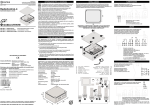
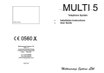
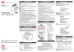
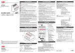
CONTRIVE S.R.L.
Via Enrico Fermi 18 I-24040 SUISIO (Bergamo)
Tel. +39 (0)35 4948236 Fax +39 (0)35 4933759
B2500.EN / 1213
CONFIGURATION
SAFETY INFORMATION
Do not install this unit near medical devices like pacemakers or hearing
aids. This unit may interfere with the operation of these devices.
www.contrive.mobi
Switch off this unit when flying.
Secure it so that it cannot be switched on inadvertently.
GSM REMOTE CONTROL
Do not install this unit near petrol stations, fuel depots, chemical plants or
blasting operations when this unit can disturb the operation of technical
equipment.
Interference can occur if this unit is used near televisions, radios or
personal computers.
0681
If the device has been stored in a cold environment, condensation can occur.
Before starting operations, the device must be absolutely dry.
Thus, an acclimatization period of at least three hours must be observed.
This device complies with Part 15 of the FCC Rules
CONTAINS FCC ID N7NQ2687
USER GUIDE
Mobi.Control 2500. 2 2 . X B
ANTENNA IS NOT PROVIDED AND
MUST BE PURCHASED SEPARATELY
STANDARD VERSION: 2500.22.XB
OTHER OPTIONS ON REQUEST
OUTPUTS
NO OUTPUT RELAYS 0
1 OUTPUT RELAY 1
2 OUTPUT RELAYS 2
ANALOG INPUTS
NO INPUTS 0
2 INPUTS 2
ANTENNA
EXTERNAL FME X
INTERNAL I
BATTERY
NO BATTERY 0
Li-Poly BATTERY B
r
In order to avoid possible damage, we recommend that you only use the
specified accessories.
These have been tested and shown to work well with this unit.
This device complies with Part 15 of the FCC Rules. Operation is subject to the
following two conditions:
¡ this device may not cause harmful interference, and
¡ this device must accept any interference received, including interference that may
cause undesired operation.
This device should be installed only by qualified personnel. Carefully read the
instruction manual in its entirety and keep it safe for future reference.
It is essential to know the information and comply with the instructions given in the
manual to ensure the fitting is installed, used and serviced correctly and safely.
This RF unit is not designed for and intended to be used in portable applications
(within 20 cm or 8 inches of the body of the user) and such uses are strictly prohibited.
This unit is not authorised for use as critical component in life-support devices or
systems unless a specific written agreement has been given.
If incorrectly installed in a vehicle, the operation of GSM device could interfere with
the correct functioning of vehicle electronics. Verification of the protection of vehicle
electronics should form a part of the installation.
Regulations must be considered to operate a vehicle’s light or horn on public roads.
No complex software or hardware system is perfect.
Bugs are always present in a system of any size.
In order to prevent danger to life or property, it is the responsibility of the system
designer to incorporate redundant protective mechanism appropriate to the risk
involved.
All units are 100% functionally tested. Specifications are based on characterisation
of tested sample units rather than testing over temperature and voltage each unit.
Contrive disclaims all liability for damage to the fitting or to other property or persons
deriving from installation, use and maintenance that have not been carried out in
conformity with this instruction manual, which must always accompany the fitting.
PRODUCT DESCRIPTION
Your Mobi.Control is the product of advanced engineering, design and craftmanship
and should be treated with care. The suggestion below will help you to enjoy this
product for many years.
Mobi.Control is an industrial DIN rail GSM modem for the supervision and control of
remote inputs and outputs by means of enhanced features available through GSM
network. Industrial standard interface and an integrated SIM card reader mean it can
be used rapidly, easily and universally to quickly implement new applications in
telemetry, telematics and remote control. All interfaces are integrated in the housing.
The connections are suitable for use in domestic and industrial environments.
Both fixed and mobile applications are allowed, as defined below:
Fixed means that the device is physically secured at one location and is not able
to be easily moved to another location.
Mobile means that the device is designed to be used in other than fixed locations
and generally in such a way that a separation distance of at least 20 cm (8 inches)
is normally maintained between the transmitter’s antenna and the body of the user
or nearby persons.
Do contact an authorized service center in the unlikely event of a fault in the unit.
¡ Mobi.Suite : freeware tool available for download : www.contrive.mobi
- linked to device through local COM port
- generating configuration SMS to be sent to the remote device
- sending configuration through device Web account
ONCE A WEB ACCOUNT HAS BEEN CREATED BY DEVICE
¡ Web interface : once a web account is available: www.webadmin.mobi
The configuration interface and Web Control requires a data connection, consider
enabling this interface depending on the application and evaluating the tariff plan
related to data transfer proposed by your Operator.
When you configure the access point to the network (APN), the device automatically
activates the data link and create its own account.
The configuration of the access point can be made using Mobi.Suite, alternatively
you can send the following SMS to the device:
xxxx APN=adr,user,pwd
xxxx
APN
user
pwd
device password
access point
APN username
APN password
DEFAULT=0000
PROVIDED BY YOUR OPERATOR
LEAVE BLANK IF NOT REQUIRED
LEAVE BLANK IF NOT REQUIRED
Example: 0000 APN=apn.operator.com,mymobi,mypassword
Once you have completed the activation, Mobi.Control will send you back an SMS
including the identifier to be used to access its Web account.
You can set up some information about the device:
IDENTIFIER
PHONE NUMBER
EMAIL ADDRESS
PASSWORD
CLOCK SETTINGS
to be included in all sent messages
assigned to SIM card
to be used within messages
to be used for local/remote access
manual / automatic
Mobi.Control can be configured so that the occurrence of specific events :
POWER SUPPLY
BATTERY
INTERNAL TEMPERATURE
RELAY OUTPUT O1-O2
DIGITAL INPUTS I1-I8
ANALOG INPUTS A1-A2
DIGITAL INPUTS C1-C2
TIME COUNTER INPUTS T1-T2
PULSE COUNTER INPUTS P1-P2
PULSE COUNTER INPUTS P1-P2
GEO POSITION
failure / restore
low / high
low / high
on / off
opening / closing
low / high thresholds
opening / closing
accumulated time threshold
accumulated pulses threshold
low / high ratio thresholds
MCC / MNC / LAC / CI change
PRODUCT FEATURES
Quad band GSM / GPRS / EDGE communication with manual / automatic selection
on bands 850 / 900 / 1800 / 1900 MHz for data, sms, data and voice applications.
Output power:
Class 4 ( 2W for GSM850 and EGSM900 )
Class 1 ( 1W for DCS1800 and PCS1850 )
Temperature:
-30 to 60°C (-40 to 85°C when relays are not in use)
-20 to 60°C recommended for battery
Relative humidity:
operating 5 to 95% non-condensing
storage & transport 5 to 95% condensation allowed outside
Enclosure:
EN-50022 rail 4 modules, polycarbonate, UL94 -V0
Overall dimensions: mm 71 x 90 x 58 ( W x H x D )
Weight:
200 g
Degree of protection: IP 40 (EN-60529 / IEC 529) properly fitted
PHONE CALL
SMS
EXTENDED SMS
TWEET
EMAIL
voice message on answer
custom text
including device status
custom text
custom text and device status
For each input / output channel is possible to define a name and set the operating
parameters.
The behavior of Mobi.Control can be configured by setting some rules:
USERS 1
USERS 2
RECIPIENTS
INCOMING CALLS
ORIGINATED CALLS
INCOMING SMS
ORIGINATED SMS
WEB SERVICES
PLC (10)
enable according to day / hour
enable according to day / hour
enable according to day / hour
behavior / timing / feedback
behavior / duration / inter-call pause
confirmation feedback
mode / pause between sending
connectin mode
name / event / commands
By means of PLC rules is possible to define up to 10 commands (the same available
from remote) that will be carried out upon the occurrence of a local event,
creating a small programmable controller.
The same commands can be scheduled to be carried out by configuring up to 100
operations on a specified date (only once) or periodically daily, weekly or yearly.
If the Web Services have been activated you can define operations associated with
sunrise and sunset time (updated weekly by date and geographical area).
The incoming SMS messages that contain no commands are discarded.
But it is possible to define some forwarding rules based on the sender's phone
number and/or based on keywords contained in the text in order to send these
messages to a phone number of your choice.
58
WARRANTIES
CONTRIVE GUARANTEES FOR TWO YEARS FROM THE DATE OF MANUFACTURE OF
ITS PRODUCT TO REPLACE, OR, AT ITS OPTION, TO REPAIR ANY PRODUCT OR PART
THEREOF WHICH IS FOUND DEFECTIVE IN MATERIAL OR WORKMANSHIP OR WHICH
OTHERWISE FAILS TO CONFORM TO THE DESCRIPTION OF ITS SALES ORDER.
CONTRIVE MAKES NO WARRANTY OF MERCHANTABILITY OR ANY OTHER
WARRANTY EXPRESS OR IMPLIED. IN NO EVENT SHALL CONTRIVE BE LIABLE FOR
CONSEQUENTIAL OR SPECIAL DAMAGES OF ANY NATURE WHICH MAY ARISE IN
CONNECTION WITH SUCH PRODUCTS.
THE WARRANTY DOES NOT APPLY IN CASE OF IMPROPER USE
Please perform the following tasks after receiving the product :
¡ Inspect the unit for damage.
If the unit appears damaged upon receipt, contact the shipper immediately.
DIMENSIONS [mm]
71
Up to 5 commands can be issued to Mobi.Control within SMS, Tweet, Email, Web.
Message must include device password (default 0000,editable). Commands will be
recognized both uppercase, lowercase and mixed, nested within other text wherever
placed inside the incoming message.
out
start1
stop1
start2
stop2
alert
noalert
sms
tweet
email
status
clock
set1
set2
thr
zero1
zero2
log
clearlog
logstatus
logemail
beep
melody
speech
way
neton
netoff
netnew
divert
nodivert
90
¡ Verify receipt of the correct unit by checking the label on the right side of the unit.
¡ If you have received the wrong model or the device does not function properly,
contact your supplier.
SWITCH OUTPUTS ON/OFF
ENABLE GROUP 1 USERS
DISABLE GROUP 1 USERS
ENABLE GROUP 2 USERS
DISABLE GROUP 2 USERS
ENABLE ALERTS TO RECIPIENTS
DISABLE ALERTS TO RECIPIENTS
SEND A DIRECT SMS
SEND A DIRECT TWEET
SEND A DIRECT EMAIL
ASK FOR DEVICE STATUS
REAL TIME CLOCK SETTINGS
CHANNEL 1 SETPOINT
CHANNEL 2 SETPOINT
ANALOG / COUNTER THRESHOLDS SETTINGS
RESET COUNTER 1
RESET COUNTER 2
ASK FOR 98 EVENTS LOG MEMORY
DELETE EVENTS LOG MEMORY
SAVE CURRENT STATUS TO LOG MEMORY
SEND CURRENT STATUS TO EMAIL ADDRESS
PLAY AN AUDIO TONE
PLAY A MELODY
PLAY A VOICE MESSAGE
GEOGRAPHIC INFORMATION
ENABLE RADIO AND NETWORK REGISTRATION
DISABLE RADIO AND RELEASE NETWORK
PERFORM A NEW NETWORK REGISTRATION
ENABLE INCOMING CALL DIVERTING
DISABLE INCOMNG CALL DIVERTING
Complete commands list and details here:
www.contrive.mobi/mobicontrol
SHORTCUT COMMANDS FOR REGISTERED USERS
Users stored into device Phonebooks are allowed to use shortcut commands that
doesn’t require password. 7 commands are predefined (editables):
S1
S2
R1
R2
P1
P2
D
send alerts to recipients using different formats and at configurable intervals:
CARE AND MAINTENANCE
¡ Do not expose the unit to any extreme environment where the temperature or
humidity are out of operating range.
¡ Do not use or store the unit in dusty or dirty areas.
¡ Do not use chemical cleaning agent on the unit or the SIM card.
¡ Do not attempt to disassemble the unit or remove any part or label.
¡ Do not expose the unit to water, rain or spilt beverages. It is not waterproof.
¡ Do not abuse the unit by dropping, knocking or violenty shaking it.
Rough handling can damage it.
¡ Do not place the unit alongside computer discs, credit or travel cards or other
magnetic media. The information contained on these devices may be affected.
¡ This unit is under your responsibility. Please treat it with care respecting all local
regulations. It is not a toy: keep it in a safe place and out of the reach of children.
¡ Treat the SIM card with the same care as your credit card: do not bend or scratch
or expose it to static electricity.
¡ Keep your unlock and PIN codes in safe place.
Mobi.Control is fully configurable by means of:
REMOTE CONTROL
Set output 1 ON
Set output 2 ON
Reset output 1 OFF
Reset output 2 OFF
Pulse output 1 (default 3”)
Pulse output 2 (default 3”)
Status SMS request
Specifying a time interval after the set command, outputs will be released once
set time has elapsed:
00 - 23
S1=DDhhmm
hh
hours
mm
minutes 00 - 59
ss
seconds 00 - 59
... or at a specified expiry date/time:
S1=DDMMYYhhmm DD
MM
YY
hh
mm
Example:
day
month
year
hours
minutes
01 -31
01 - 12
00 - 99
00 - 23
00 - 59
S1=083000 S2=2504141230 text D alien trailer
turn ON output 1 for 8 hours and 30 minutes
turn ON output 2 until April 25, 2014 12:30
send back a status SMS
CALL COMMANDS FOR REGISTERED USERS
Behavior of Mobi.Control at incoming calls from Registered Users can be set to:
NO ACTION
Clip feature is disabled, nothing happens on incoming calls.
PULSE(default 3”)
Selecting this mode, incoming voice (or fax) call will turn on out 1 for the specified
time. A data call will do the same on output 2. Call terminated without answer.
TOGGLE
Incoming voice (or fax) call will toggle output 1 on to off or vice-versa, data calls will do
the same on output 2. If the user waits online, Mobi.Control will confirm the operation
by means of voice messages.
REVERSE
Any incoming call from registered users will start a sequence: output 1 pulse, pause,
output 2 pulse (all times configurable). Call terminated without answer.
1
2
3
ANSWER
1 ON
2 ON
1 PULSE
Mobi.Control answers the incoming call, accepting up
4
5
6
to 5 control codes on the telephone keypad.
* (star) to confirm once all commands are issued
# (hash) to delete and start from the beginning
Voice prompt will guide during the operation.
1 OFF
2 OFF
2 PULSE
7
*
8
0
9
#
CONFIRM STATUS
DELETE
INSTALLATION
COM PORT
DIGITAL INPUTS
BATTERY
This unit can be installed on any standard EN-50022 rail by simple snap-in.
For safe operation, the unit must be installed only by qualified personnel in an
enclosure which prevents accidental contact with hazardous voltages.
Protection degree IP40 must be guaranteed, raised to IP54 for open air application.
Easy configuration, local control, tracing and other advanced features are available
through serial communication link. Configuration software MobiSuite for PC running
®
®
Microsoft Windows is available for free download at www.contrive.it.
Up to 8 SPST contacts can be wired to terminals 05 – 12, status reported on LED
indicators [D]. Internal power supply is available at terminal 04.
Independent debounce time setting for each input in the range 1... 300 seconds.
This unit could be equipped with an high efficiency Lithium-Ion Polymer battery
having a long life, that largely depends on temperature and frequency of main power
failures, used in normal condition can last several years.
If the battery is already connected, you just need to provide power supply to operate
Mobi.Control. The battery charging process will start.
If the battery is not connected, proceed as follows:
A
1
A. Analog and digital input terminals
12 x 2,5mm2 (AWG14)
1 2 3 4 5 6 7 8 9 10 11 12
B. Output green LED indicators
B C
C. GSM operation blue LED indicator
¡ OFF
No power supply
¡ ON
D
8
RJ45 1. RxD
2. GND
3. TxD
4. SPK
5. CTS
6. SPK
7. RTS
8. +5V
200ms ON / 2s OFF
à à
Module switched ON
Registered on the network
¡ QUICK FLASH
F
E
õ
X
D. Digital input red LED indicators
E. Outputs, counter inputs and power
supply terminals
2
8 x 2,5mm (AWG14)
C
B
G. Analog input selector
Disconnect all power
supplies and battery before
to insert or remove the
SIM card.
Replace the plastic cover
before to operate the unit.
G
full scale value
zero (offset)
unit
1 ... 100000
0 ... 90%
any text
WARNING
If you insert a SIM card that asks for a PIN number different from that
stored into Mobi.Control, the device will not operate.
If you enter the PIN 3 times incorrectly, SIM card will lock up and you must
provide the PUK (PIN Unblocking Key).
WIRING
01.
02.
03.
04.
05.
06.
07.
08.
09.
10.
11.
12.
13.
14.
15.
16.
17.
18.
19.
20.
Negative
Analog Input 1
Analog Input 2
Positive 3,3VDC
Digital Input 1
Digital Input 2
Digital Input 3
Digital Input 4
Digital Input 5
Digital Input 6
Digital Input 7
Digital Input 8
Output common
Relay output 1
Relay output 2
—
Counter input 1
Counter input 2
Power supply
Power supply
Input range
Voltage drop
Resolution
Accuracy
Impedance
0 ... 20 mA
2 V @20mA
0,02 mA
±1%
100 W
Input range
Resolution
Accuracy
Impedance
0 ... 10 V
0,01 V
±1%
25 kW
C
C
B
Input range
Resolution
Accuracy
Impedance
0 ... 2 V
0,002 V
±1%
5 kW
B
C
B
Input range
Resolution
Accuracy
NTC
5V
6,8V
1 2
2. Pull the front cover and
keep it in a safe place.
1
3. Unplug battery connector
from the socket [K].
4. Replace the front cover to
close the unit.
Disconnect the battery if the
device is put out of service.
20V
1 2 3 4 5 6 7 8
External power supply for inputs must meet SELV circuits requirements according
to EN60950 / IEC950: maximum allowed voltage is 60VDC.
1 2
B:3435@25÷85°C
PRECISION TEMPERATURE SENSOR
[ TEXAS INSTRUMENTS ]
+125
+1205
+100
+1049
+25
+580
0
+424
-25
+268
-40
+174
LM60
1 2
POWER SUPPLY
This unit can be supplied either by alternating or direct current, polarity independent,
in a wide voltage range. Power supply connection terminals 19 and 20.
The power supply must not be shared with other equipment: suggested power
supply source is a simple 12VAC / 10VA transformer.
Supply Voltage
9,5 ... 35 V DC
9,5 ... 27 V AC
Power consumption
< 200 mW IDLE
PEAK
<5W
3...9 VDC
5mA @ 4V
4V DC ±20% AT TERMINAL 04
> 200 / 20 ms CONFIGURABLE
< 2,5 Hz
1 2
TO TERMINAL 04
TEMP °C OUT mV
2V
424
200
°C
Two special digital inputs are available at terminals 17 – 18.
Inputs can be used as a standard digital input in addition to 8 channels already
available (without LED indication).
Independent debounce time setting for each input in the range 1... 300 seconds.
Inputs can operate also as a pulse or time counter. SPST contacts, magnetic reed or
hall sensor and electronic switches can be used. Internal power supply is available at
terminal 04, using electronic switches this is the positive leg.
1 2
Active devices could be powered directly from Mobi.Control when voltage and output
are compatible and total current consumption remains within 50 mA.
LM60
COUNTER INPUTS
Input voltage
Input current
Output voltage
Pulse width
Frequency
0 ... 2 V
0,1 °C
±1 °C
10 kW @25°C
SHIELDED CABLE COULD BE USED FOR LONG LINES
SHIELD CONNECTED TO NEGATIVE TERMINAL 01 ONLY
LEAVE OTHER SIDE UNCONNECTED
SET : INPUT SWITCH
ZERO
FULL SCALE
UNIT
Regulated 3,3V – 50 mA MAX available at terminal 04 respect to negative terminal 01.
On battery equipped units such power supply is provided also when main power
supply is missing; to prevent permanent damage to battery external loads must be
disconnected when voltage drops below 3VDC.
When inputs are supplied by external source, negative must be connected to
terminal 01. Insert a zener diode to keep inputs voltage within 9VDC.
Multiple options can be used, see example below:
¡ inputs 1 and 2 using internal supply
¡ inputs 3 and 4 using external 5VDC supply
¡ inputs 5 and 6 using external 12VDC supply reduced by zener diode 6,8V
¡ inputs 7 and 8 using external 24VDC supply reduce by zener diode 20V
12V
NTC temperature sensor measuring in the range -10...60°C can be directly
connected to analog inputs: set inputs for 2V and enable NTC software linearization.
1. Positive +2,7...12VDC
2. Out 6,25mV/°C +424mV OFFSET
3. Negative
POWER SUPPLY, INPUTS AND COM PORT
MUST MEET THE DEMANDS PLACED ON
SELV (SAFETY EXTREMELY LOW VOLTAGE)
CIRCUITS ACCORDING TO EN60950 / IEC950
1. Push with two fingers on
top and bottom sides of
front cover to release it.
24V
F. SIM card holder
3V and 1,8V SIM card allowed
SIM PIN
Put your SIM card into a cellular phone
and program it so it won't ask for the PIN:
the SIM card is 'open' and someone
could steal the SIM card, use it and read
the information inside.
You may protect the SIM card later using
MobiSuite configuration software.
1
BATTERY SPECIFICATIONS
X. Antenna connector
NOT AVAILABLE FOR IPEX VERSION
1 2 3 4 5 6 7 8
Disconnect power supply and
all live circuits. Remove front
cover to access the inside :
CAN BE USED TO POWER
THE UNIT
Software configuration available for each input:
Module switched ON
Registered on the network
Communication in progress
2
MobiLink USB cable:
2505.00.03
Up to 2 analog signal can be connected at terminals 02 – 03 respect to negative
terminal 01. Select input mode by means of dipswitch [G] before to operate the unit.
200ms ON / 600ms OFF
13 14 15 16 17 18 19 20
Input voltage 3 ... 9 VDC
Input current 5mA @ 5V
Output voltage 3,3V DC AT TERMINAL 04
MobiLink RS232 cable:
2505.00.01
ANALOG INPUTS
PERMANENTLY
Module switched ON
Not registered on the network,
missing SIM or invalid PIN
¡ SLOW FLASH
RS-232
300 ... 115200 bit/s
8N1
Hardware handshake
DB9
.2
.5
.3
..8
..7
.-
õ
õ
F. RJ socket - COM port
An automatic 2-pole circuit breaker or equivalent protection capable of disconnecting circuit in the event of short circuit or over-current condition should be placed
on the AC mains side of power supply unit. Maximum permissible connection length
between device and low voltage supply source is 3 m.
OUTPUTS
Two SPST relay contacts are available for process or appliance control at terminals
14 – 15, status reported on LED [B]. Common return at terminal 13.
Rated current 3 A
Rated voltage 250 VAC
Breaking voltage 277 VAC
Max breaking capacity 750 VA
Minimum contact load 1 mA, 5 VDC
Cadmium free contacts
Insulation to IEC60664
Voltage rating 277 V
Pollution degree 2
category as basic insulation III
category as reinforced insulation II
Surge voltage coil contacts: 5000VRMS
Dielectric strength
coil-contacts 3000VRMS
open contact circuit 750VRMS
1 2
To prevent relay contacts from damaging, an external protection
should be provided (fuse or similar), according to the relay
breaking capacity.
K
4,2V FULL CHARGE
Voltage
3,7 V
Capacity
> 320 mAh 1.26 Wh
Temperature -20...60°C 0...45°C CHARGING
Before a long period of inactivity switch off
the unit to prevent deep discharge of the battery.
This operation can be accomplished using
Mobi.Suite terminal or from the console
by issuing the command AT+CPOF
Battery status is reported at any time by the
LED located near the connector:
OFF
OFF
Charge OFF
RED
OFF
Charge in progress
OFF
GREEN
Charge completed
RED
GREEN
Bad or NO battery
RECYCLING OPTIONS
AVAILABLE IN YOUR AREA
MUST BE CONSIDERED
WHEN DISPOSING
BATTERIES !
DO NOT DISPOSE OF
IN FIRE !
ANTENNA
The antenna must be connected to the RF interface, implemented as a 50W connector available in 2 different options:
¡ External FME male coaxial jack at the end of a short RG178 cable stub exiting
from the bottom left side of the unit.
¡ Internal IPEX connector suitable for embeddable antennas.
The antenna must fulfil the requirements given below:
Frequency TX
880 to
915 MHz
1710 to
1785 MHz
824 to
849 MHz
1850 to
1910 MHz
Frequency RX
925 to
960 MHz
1805 to
1880 MHz
869 to
894 MHz
1930 to
1990 MHz
Impedance
VSWR
50 ohms
RX max
1.5 : 1
TX max
1.5 : 1
Polarization
Linear
Typical gain
0 dBi in one direction at least
The gain must not exceed 8,4dBi @ 850MHz and 3,5dBi @ 1900MHz.
We recommend a VSWR max of 1.5:1 although a VSWR max of 2:1 can be accepted
without affecting performance and certification.
The DC impedance is floating but there is no problem when using antennas that
present a short to ground.
© COPYRIGHT 2012 CONTRIVE SRL ITALY. SOME RIGHTS RESERVED.
INFORMATION CONTAINED IN THIS DOCUMENT ARE SUBJECT TO CHANGE WITHOUT
NOTICE. PRODUCT NAMES, CORPORATE NAMES OR TITLES USED WITHIN THIS
DOCUMENT MAY BE TRADEMARKS OR REGISTERED TRADEMARKS OF OTHER
COMPANIES AND ARE MENTIONED ONLY IN AN EXPLANATORY MANNER TO THE
READERS’ BENEFIT, AND WITHOUT INTENTION TO INFRINGE.
WHILE EVERY EFFORT HAS BEEN MADE TO MAKE SURE THE INFORMATION IN THIS
DOCUMENT IS CORRECT, CONTRIVE CAN NOT BE LIABLE FOR ANY DAMAGES