1
Operating instructions
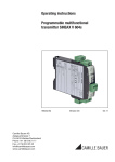
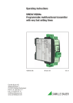
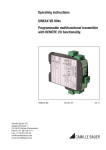
SINEAX VC604s
Programmable
Safety Value Converter
VC604s Be
Camille Bauer AG
Aargauerstrasse 7
CH-5610 Wohlen/Switzerland
Phone +41 56 618 21 11
Fax +41 56 618 21 21
[email protected]
www.camillebauer.com
Version 00
02.12
Operating instructions
Programmable multifunctional transmitter SINEAX VC604s
First read, then …
1. Functional description
The unobjectionable and safe operation presupposes that these operating instructions
have been read and understood!
VC604s is a multifunctional transmitter for top-hat rail assembly with the following main characteristics:
● Measurement of DC voltage, DC current, temperature
(RTD, TC) and resistance
● Sensor connection without any external jumpers
Devices may only be disposed of in a professional manner!
Contents
1. Functional description ................................................. 2
2. Connection to a PC and communication via
CB-Manager ................................................................ 2
3. Block diagram .............................................................. 3
4. Technical data .............................................................. 4
5. Signal flow ................................................................... 7
6. Modbus interface ......................................................... 8
6.1 EIA-RS-485 Standard ............................................ 8
6.2 Coding and addressing ......................................... 8
6.3 Mapping ................................................................ 9
6.4 Device identification .............................................. 9
6.5 Measured values ................................................. 10
6.6 Configuration parameters.................................... 11
7. Electric connections .................................................. 18
8. Dimensional drawing ................................................. 19
9. Accessories ............................................................... 19
10. Conformity declaration .............................................. 20
● 2 inputs (e.g. for sensor redundancy or difference
formation)
● 1 output (U or I)
● 2 inputs can be linked with each other and allocated
to the 2 outputs which enables calculations and
sensor monitoring (e.g. prognostic maintenance of
sensors)
● System capability: Communication via Modbus
interface
● 2 freely programmable relays with changeover contacts, e.g. for limit or alarm signalling
● AC/DC wide-range power supply unit
● Pluggable high-quality screw terminals
All settings of the instrument can be adapted to the measuring task by PC software. The software also serves visualising,
commissioning and service.
2. Connection of SINEAX VC604s to a PC and communication via CB-Manager.
VC 604s communicates with a PC (CB-Manager) via an
RS 232/RS485 interface and a MODBUS protocol.
Subsequently, enter the following settings under Options /
Interface / Settings:
Select the following settings in this respect:
Select the RS 232/ RS485 interface under Options / Interface.
This is also applicable if an RS485/USB converter is used
and the converter is connected to the computer via the
USB connection.
2
Operating instructions VC604s Be
Camille Bauer
The existing COM ports are determined as the communication interface when starting the program and selecting
RS232/RS485. Only COM ports found are available for
selection.
The COM port of an external RS232 or RS485 converter
may be determined (and, if required, changed) via the
Windows system control.
Example for Windows XP: System control => System
Limiting the range of possible device addresses speeds
up the search of connected devices considerably.
Example: If only 2 devices are connected, it makes sense
to select the address range from 1 to 2.
All settings are stored as the program is terminated. If the
COM port is not available upon the next start of the program (e.g. because the converter has not been plugged in)
another valid interface is set.
To determine which COM port has been allocated to
the RS485 converter (if required), please proceed as
follows:
This example shows the COM ports of a PCMCIA card
and a USB-RS232 converter:
- Silicom Serial Card: COM1
- USB-RS232 adapter: COM4
USB / RS485
CONVERTER
Tx
B1 A1 T1 T2
HALF RS485
USB
POWER
T2
T1
Rx
If you use the Camille Bauer USB-RS485 converter
(Article Number 163189), the same is to be connected as
follows:
A1
B1
GND
3. Block diagram
Power supply
3,7 kV
3,7 kV
3,7 kV
2,3 kV
Measuring
Inputs
A
D
Relay
contact 1
2,3 kV
μP
Relay
contact 2
D
A+ Analog
A– output
A
0,5 kV
Tx
Rx
Camille Bauer
Operating instructions VC604s Be
+
–
Bus
GND
3
Resistance measurement, teletransmitter, potentiometer
4. Technical data
Measuring range limits See Table 1
Table 1: Input variables, measuring ranges
Measurement type
DC voltage [mV]
DC current [mA]
Resistance [Ω]
Measuring range
Wiring
Minimum span
–1000 … 1000 mV
–50 …
2 mV
50 mA
0,2 mA
0 … 5000 Ω
8Ω
RTD Pt100
–200 ... 850 °C
20 K
RTD Ni100
–60 ... 250 °C
15 K
TC Type B
0 ... 1820 °C
635 K
TC Type E
–270 ... 1000 °C
34 K
TC Type J
–210 ... 1200 °C
39 K
TC Type K
–270 ... 1372 °C
50 K
TC Type L
–200 ... 900 °C
38 K
TC Type N
–270 ... 1300 °C
74 K
TC Type R
–50 ... 1768 °C
259 K
TC Type S
–50 ... 1768 °C
265 K
TC Type T
–270 ... 400 °C
50 K
TC Type U
–200 ... 600 °C
49 K
TC TypeW5Re-26Re
0 ... 2315 °C
135 K
TC TypeW3Re-25Re
0 ... 2315 °C
161 K
2, 3 or 4-wire connection
Resistance teletransm. Type WF and WF DIN
Measuring current
0.2 mA
Line resistance
30 Ω per line,
in 2-wire connection adjustable or
calibratable
Measuring input 2
Direct current
Measuring range mA
Same as Measuring input 1
Direct voltage
Measuring range mV
Same as Measuring input 1
Resistance thermometer RTD
Same as Measuring input 1 except:
Wiring
2 or 3-wire connection
Thermocouples TC
Same as Measuring input 1
Resistance measurement, teletransmitter, potentiometer
Same as Measuring input 1 except:
Wiring
2 or 3-wire connection
Measuring input 1
Please note
Direct voltage
Measuring inputs 1 and 2 are galvanically
connected. If 2 input sensors or input variables are used, observe combination options
in Table 3 (page 18) and circuit instructions
(page 17)!
Measuring range mV
For limits see Table 1
Ri > 10 MΩ, continuous,
overload max. ±1200 mV
Direct current
Measuring range mA
For limits see Table 1
Ri = 11 Ω, continuous,
overload max. ±50 mA
Resistance thermometer RTD
Resistance measurement
types
Pt100 (IEC 60751),
adjustable Pt20…Pt1000
Ni100 (DIN 43760),
adjustable Ni50…Ni1000
Measuring range limits See Table 1
Wiring
2, 3 or 4-wire connection
Measuring current
0.2 mA
Line resistance
30 Ω per line,
in 2-wire connection adjustable
or calibratable
Thermocouples TC
Thermocouples
Type B, E, J, K, N, R, S, T
(IEC 60584-1)
Type L, U (DIN 43760)
Type W5Re-W26Re, W3ReW25Re (ASTM E988-90)
Measuring range limits See Table 1
Cold junction
compensation
Internal (with installed Pt100),
with Pt100 on terminals, external with reference junction
thermostat –20…70 °C
4
Analog output
The two outputs are galvanically connected and have a common earth. Voltage and current output software-configurable.
Direct current
Output range
Burden voltage
Open circuit voltage
Limit
Residual ripple
Source resistance
Direct Voltage
Output range
Load
Current limit
Limit
Residual ripple
Source resistance
± 20 mA,
range may be freely set
max. 12 V
< 18 V
Adjustable, max. ±22 mA
<50 μA pp (after low pass 10 kHz)
>5 MΩ
± 10 V,
range may be freely set
max. 20 mA
Approx. 30 mA
Adjustable, max. ±11 V
<20 mV pp
(after low pass 10 kHz)
<2 Ω
Output settings
Limit
Gain/offset trimming
Inversion
Operating instructions VC604s Be
Camille Bauer
Alarm signalling
Relay contact outputs
Contact
Switching capacity
1 pole, changeover contact
AC: 2 A / 250 V AC
DC: 2 A / 30 V
Time delay
Alarm LED “ERR”
Relay contact
Bus/programming connection
Interface, protocol
Baudrate
RS-485, Modbus RTU
9,6...115,2 kBaud, adjustable
Output value
in case of a fault
Transmission behaviour
Measured variables
for the outputs
Transmission function
Settling time:
Input 1
Input 2
Input 1 + Input 2
Input 1 – Input 2
Input 2 – Input 1
Input 1 · Input 2
Minimum value, maximum
value
or mean value of Input 1
and Input 2
• Sensor redundancy
Input 1 or Input 2
Linear,
user-specific via
basic value table
(24 basic values per measured
variable)
Adjustable 1…30 s
Number of limit values 4
Measured variables for
limit values
• Input 1
• Input 2
• Measured variable for outputs
• Input 1 – Input 2
(e.g. drift monitoring in case of
2 sensors)
• Input 2 – Input 1
(e.g. drift monitoring in case of
2 sensors)
Functions
Absolute amount
Gradient dx/dt (e.g. temperature
gradient monitoring)
Time delay
Adjustable 0…3600 s
Signaling
Relay contact, alarm LED,
Status 1
Relay contact, alarm LED,
Status 1
Output value in case of a fault
Other monitoring operations
Sensor redundancy
Camille Bauer
For sensor breakage and short
circuit, value adjustable
–10…110%
Rated voltage UN
Tolerance
24…230 V DC *
±15%
100…230 V AC, 45…400 Hz
±15%
* In case of a power supply voltage >125 V DC, the power
supply circuit must contain an external fuse.
Power consumption
<3 W bzw. 7 VA
Displays at the instrument
LED
ON/ERR
Color
Function
green
Power on
red
Alarm
green flashing
Communication activ
1
yellow
Relay 1 on
2
yellow
Relay 2 on
Configuration, programming
Operation with PC software «CB-Manager»
Accuracies (according to EN/IEC 60770-1)
Reference conditions
Ambient temperature
Power supply
Reference value
Settings
Sensor breakage and
short circuit monitoring measuring input
Drift monitoring
When the relay is activated,
the yellow LED shines,
invertible
Power supply
•
•
•
•
•
•
•
Limit values and monitoring
Signalling
Adjustable 0…60 s
Installation position
23 °C ± 2 K
24 V DC
Span
Input 1: Direct voltage mV,
0…1000 mV
Output 1: 4…20 mA, burden
resistance 300 Ω
Mains frequency 50 Hz,
Setting time 1 s
Input 2, output 2, relay,
monitoring off or not active
Vertically, detached
Basic accuracy
At reference conditions ±0.1%
Other types of measurement and input ranges:
Monitoring of measured value
between 2 input sensors for a
certain period of time (e.g. due to
different sensor response times).
If this time is exceeded, an alarm
is signalled.
(See Limit values 1 and 2)
Measurement with 2 temperature
sensors; if Sensor 1 fails (fault)
Sensor 2 is activated for bridging (see measuring variable for
outputs).
RTD Pt100, Ni100
±0.1% ±0.2 K
Resistance measurement ±0,1% ±0.1 Ω
TC Type K, E, J, T, N, L, U ±0.1% ±0.4 K,
measurement value > –100 °C
TC Type R, S
±0.1% ±2.4 K
TC Type B
±0.1% ±2.4 K,
measurement value > 300°C
TC W5Re-W26Re,
W3Re-W25Re
±0.1% ±2.0 K
DC voltage mV
±0.1% ±0.015 mV
DC current mA
±0.1% ±0.0015 mA
Operating instructions VC604s Be
5
Additional error (additive)
Type label
High range minimum value
(Minimum value >40%
of maximum value):
±0.1% of maximum value
Small output range
±0.1% * (reference range / new
range)
Cold junction
compensation internal typical ±3 K
Influencing factors
Ambient temperature
Long-term drift
Common mode
influence
±0.1% per 10 K at reference
conditions
other settings: basic accuracy
and additional errors per 10 K
±0.1%
±0.01%
Ambient conditions
Operating temperature
Storage temperature
Relative humidity
Annual average
Range of utilisation
–25 … +55 °C
–40 … +70 °C
≤75%, no dew
Internal room up to 2000 m above
sea level
Installation details
Design
Dimensions
Assembly
Terminals
Weight
Top-hat rail housing U4
Combustibility class V-0
according to UL 94
See dimensional drawing
For snap-on fastening on top-hat
rail (35 x 15 mm or 35 x 7.5 mm)
according to EN 50022
Pluggable, 2.5 mm2
0.14 kg
Product safety, regulations
Electromagnetic
compatibility
Ingress protection
(acc. IEC 529 or EN 60529)
EN 61000-6-2 / 61000-6-4
Electric design
Degree of pollution
Between power supply and
all circuits and between
the measuring input (1 + 2)
and all circuits
Acc. IEC or EN 61010
2
Reinforced insulation
overvoltage category III
Working voltage 300 V
Test voltage 3.7 kV AC rms
Between output
(1 + 2) and relay contact
Reinforced insulation
overvoltage category II
Working voltage 300 V
Test voltage 2.3 kV AC rms
Functional insulation
Working voltage <50 V
Test voltage 0.5 kV AC rms
EN 60068-2-1/-2/-3
EN 60068-2-27 Shock:
50g, 11ms, sawtooth,
half-sine
EN 60068-2-6 Vibration:
0.15mm/2g, 10...150Hz,
10 cycles
Between output (1 + 2)
and the bus connection
Environmental tests
6
Explanation of symbols on the type label
Symbol
Meaning
Double insulation, device of protection class 2
CE conformity mark. The device fulfills the
requirements of the applicable EG directives
Caution!
General hazard point.
Read the operating instructions.
The instruments must be only be disposed of
in the correct way!
Housing IP 40
terminal IP20
General symbol: Input
General symbol: Output
General symbol: Power supply
General symbol: Communication
General symbol: Relay
Operating instructions VC604s Be
Camille Bauer
5 Signal flow
The following diagram shows the VC604s signal flow. All relevant measured variables and parameters determining the signal
flow are represented.
Input 1
Input 2
Sensortable
TSET
INPUT1
Legend
Setting time
Measured variables
Configuration, paramerters
INPUT2
SCALE1
SCALE2
Output link
MATRIX
Transm.
behaviour
- x^2
Limit value link
- TAB1, TAB2
MEAS1
MEAS2
Measured
value 1
Measured
value 2
Limit value
delay
Limit value 1 STATUS1
STATUS1
Breakage
Short circuit
Limit value
delay
Limit
value 2
Limit value 3 STATUS3 Limit value 4
ALARMSETA
(without inversion)
Value in case of a fault
Alarm delay
Rise, drop
Alarm1 STATUS1
inv
ALARMSETB,
Bit 7
OUTSET2, Bit 6,7
STATUS1, Bit 4-5, 7-8
Relay 1 status
Camille Bauer
STATUS3 Alarm3
Alarm2
ALARMSETA,
Bit 7
ERRVAL2
Trimming
OUTPUT1
Output 1 [mA / V]
ALARMSETB
(without inversion)
Alarm
link
STATUS1
Breakage
Short circuit
OUTSET2
ERRVAL1
TRIM1
TONLIMITB
TOFFLIMITB
Limit value 1,2
TON
TOFF
OUTSET1, Bit 6,7
STATUS1, Bit 4-5, 7-8
LIMIT4ON
LIMIT4OFF
Limit value 3,4
Output 2 [%]
Limit
OUTSET1
LIMIT4
Meas. variable
limit value 4
LIMIT3OFF
LIMIT3ON
PERCENT2
Output
behaviour
LIMIT3
Meas. var.
limit
value 3
LIMIT2ON
LIMIT2OFF
LIMIT1OFF
LIMIT1ON
TONLIMITA
TOFFLIMITA
Output 1 [%]
LIMITB
LIMIT2
Meas. variable
limit value 2
LIMIT1
Meas. variable
limit value 1
- inv
PERCENT1
Limit value link
LIMITA
TRIM2
Alarm
Relay 1
LED Relay 1
Relay 2 status
Relay 2
LED Relay 2
OUTPUT2
Operating instructions VC604s Be
7
6. Modbus interface
System requirements
6.1 EIA-RS-485 Standard
Cable:
The EIA-RS-485 standard defines the physical layer of the
Modbus interface.
Twisted, 2-wire line, wave resistance 100
to 130 Ω, min. 0.22mm2 (24AWG)
Line length:
Maximum 1’200m depending on the
transmission rate
Participants:
Maximum 32 per segment
Rate:
9’600, 14’400, 19’200, 38’400, 56’000,
57’600, 115’200 Baud
Mode:
11 bit format - 2 stop bit without parity
or 1 stop bit with even/uneven parity
Coding
The data is transmitted in serial form via the 2-wire bus.
The information is coded as a difference signal in the NRZ
code. Positive polarity signals a logic 1, negative polarity
signals the logic 0.
Connections
A shielded, twisted, 2-conductor cable should be used as
a bus cable. Shielding serves improved electromagnetic
compatibility (EMC). Depending on the source of information, the description of Conductor A and B is contradictory.
6.2 Coding and addressing
Addressing
In the telegram, all data addresses refer to zero. The first data
element is always addressed via the 0 address. For example,
the coil which is known as "Coil 1" in the device, is addressed
as "Coil 0" in the telegram. Coil 127 is addressed as 0x007E.
Holding register 40001 is addressed as Register 0 in the
telegram. The function code of the telegram already states
that a "holding register" is concerned. Consequently, the
reference to "4XXXX“ is implicit.
The potential difference of all bus participants may not exceed
± 7V. Therefore, the use of a shield or a third conductor (ref
line) is recommended to create potential equalisation.
+ line
– line
ref line
Topology
+5V
Both ends of the bus cable
must be equipped with a line
390
terminator. Supplementing the RS-485 A/P +
line termination resistance RT
220
of the EIA-RS-485 standard an
RS-485 B/N –
additional resistance RU (pul390
lup) must be wired against the
ref line
supply voltage and a resistance
0V
RD (pulldown) against the reference potential. These two resistances ensure a defined idle
potential on the line when none of the participants is sending.
Master
Slave
4
<2m
Slave
3
Slave
1
Slave
2
Slave
5
OK
Slave
3
Master
Slave
2
Holding register 40108 is addressed as 0x006B (107 decimal).
Serialisation
The specification defines the telegrams as byte sequences.
The respective physical layer (RS485, Ethernet) is responsible
for the correct serialisation of the bytes (MSB or LSB First).
RS485 (UART, COM) transmits the "Least Significant Bit“
first (LSB First) and adds the synchronisation and backup
bits (start bit, parity bit and stop bit).
Start
1
2
3
4
5
6
7
8
Par Stop
Bits
Bits are represented within a byte in a conventional manner
with the MSB (Bit 7) leftmost and the LSB (Bit 0) rightmost
(0101’1010 = 0x5A = 90). An example for the inquiry of Coils
20 to 40 of Slaves 17.
Byte
Inquiry
Response
0
Slave address
0x11
Slave address
1
Function code
0x01
Function code
0x01
2
Start address
0x00
Byte count
0x03
3
19 = Coil 20
0x13
Byte 0
0xCD
4
Number
0x00
Byte 1
0x6B
5
20…40 = 21
0x15
Byte 2
0x01
0x11
The start address in the inquiry plus the bit position in response
byte 0 corresponds to the coil address. Commenced bytes
are completed with zeros. Coil 27...20 = 0xCD = 11001101b
→ Coil20 = ON, Coil21 = OFF, Coil22 = ON, etc.
NO
Slave
1
8
Operating instructions VC604s Be
Camille Bauer
Bytes
Modbus does not know a byte or character data type (see
address space). Strings or byte arrays are mapped in "holding registers“ (2 characters per register) and transmitted as
a "character stream", e.g. "Hello_World“.
Register
HEX
char
Register
HEX
char
40101
40102
Ox4865
‚H’ ‚e’
40104
0x576F
‚W’ ‚o’
Ox6C6C
‚l’
‚l’
40105
0x726C
‚r’
40103
Ox6F5F
‚o’ ‚_’
40106
0x6400
‚d’
‚l’
Words
Registers or words are transmitted according to specification
in "Big Endian“ format, e.g. Read Holding Register 40101
of Slave 17.
Real
Modbus does not know any data types to represent floating
point numbers. On principle, any data structures may be
mapped on the 16Bit register ("cast“). The IEEE 754 standard
is the most used standard to represent floating point numbers.
Bit
31
24 23
16 15
8 7
0
Syntax
Address
Start address of the described data block (register, coil
or input status)
Description
Unique variable or structure description
Data type
Data type of variable (U: unsigned, INT: integer, 8/16/32
bit, REAL or CHAR[..])
#
Offset from the start address in the data type unit, for
Byte 0: Low, 1: High byte
Default
Value upon derlivery or after a hardware reset
Description
Exact details concerning the variable described
6.4 Device identification
The device is identified by "Read Slave ID“.
Function 11h: Report Slave ID
Master telegram:
Device
address
Function
CRC
ADDR
0x11
LO
HI
V E E E E E E E E M M M M M M M M M M M M M M M M M M M M M M M
Exponent
Mantissa
Slave telegram:
Algebraic sign
The first register contains Bits 15 – 0 of the 32-bit number
(bit 0…15 of the mantissa).
The second register contains Bits 16 – 32 of the 32-bit number
(algebraic sign, exponent and Bit 16- 22 of the mantissa).
6.3 Mapping
Address space
The address space may be divided into 4 address spaces
according to the 4 types of data.
Space
r/w
Coil
Readable
Writeable
Address area
Function code
00001 - 09999
0x01
0x05
0x0F
Read Coil Status 1)
Force Single Coil 1)
Force Multiple Coils 1)
Discrete input
Only reada10001 - 19999
ble
0x02
Read Input Status 1)
Input register
Only reada30001 - 39999
ble
0x04
Read Input Register 1)
Readable
Writeable
0x03
0x06
0x10
Read Holding
Registers
Force Single
Register 1)
Preset Multiple
Registers
Holding
register
1)
40001 - 49999
Device
Address
Function
Number
data bytes
0x11
3
Device
ID
Sub-ID
Device
Description
0x01
0x00
VR660
Temperature controller
ADDR
Slave
ID
Sub
ID
Data
2
CRC
LO
HI
0x02
0x00
A200R
Display
0x03
0x01
CAM
Universal measuring unit for heavy current
variables
0x04
0x00
APLUS
Multifunctional display
0x05
0x00
V604s
Universal transmitter
0x05
0x01
VB604s
Universal transmitter multi in/out
0x05
0x02
VC604s
Universal transmitter second relay
0x05
0x03
VQ604s
Universal transmitter fast setting time
Device information
Adress
Description
Data type
Description
41076
DEVICE
UINT16
Device type
Bit
0
1
2
not implemented
To reduce the commands, the device image was represented
as far as possible in "holding registers".
3-15
Description
Reserved
Reserved
0: V / mA inputs
1: 2 x mA inputs
Reserved
Segments
Address
Description
Permitted function codes
40209 - 40210
40257 - 40284
40515 - 40516
40517 - 40761
Actions
Measured values, status
Settings (Modbus)
Configuration data
0x03
0x10
Read Holding Registers
Preset Multiple Registers
41076
Device type
0x03
Read Holding Registers
Camille Bauer
Operating instructions VC604s Be
9
6.5 Measured values
Triggering action
Address
Description
Data type
40209
ACTION
UINT16
40210
#
Default
Description
0
This register starts actions.
ACTDAT
Action
Description
18
Input 1: With short-circuited input terminals, the line calibration is realised and the measured
parameters are stored in the device.
This procedure is indicated by a flashing green LED.
19
Line calibration at Input 2 (same as Input 1)
Additional information for the implementation of an action.
Simulation of output variables
• Writing into the PERCENT1, PERCENT2, OUTPUT1, OUTPUT2 registers interrupts the signal flow to the respective
variable and the desired value is specified (However, percent and output value cannot be simulated simultaneously).
The status of the simulation mode can be read in the STATUS2 status register.
• The simulation mode is terminated by writing 0 into the respective bits in the STATUS2 register.
Current measured variables
Address
Description
Data type
40257
STATUS1
UINT16
#
Default
0
Description
Status 1
Bit
0
1
2
3
4
5
6
7
8
9
10
11
12
13
14
15
40258
STATUS2
UINT16
0
Description
Reserved
Reserved
Device fault
Parameter fault
Sensor breakage
Sensor short circuit
Reserved
Sensor breakage
Sensor short circuit
Reserved
Alarm 1
Alarm 2 (relay 1 status before inverting)
Limit value 1
Limit value 2
Relay 1 status
Device reset or new parameter values
Input 1
Input 1
Input 2
Input 2
Status of the simulation mode: A set bit indicates the simulation mode of the respective register.
Bit
0
1
2
3
Description
Output 1 (PERCENT1)
Output 1 (OUTPUT1)
Output 2 (PERCENT2)
Output 2 (OUTPUT2)
The simulation mode is terminated by writing zeros into the respective bit positions (0..3).
40259
INPUT1
REAL
0.0
Measured value Input 1
40261
INPUT2
REAL
0.0
Measured value Input 2
40263
MEAS1
REAL
0.0
Measured variable for Output 1
40265
MEAS2
REAL
0.0
Measured variable for Output 2
40267
LIMIT1
REAL
0.0
Measured variable for Limit value 1
40269
LIMIT2
REAL
0.0
Measured variable for Limit value 2
40271
T_JUNCTION1 REAL
0.0
Cold junction temperature Input 1
40273
T_JUNCTION2 REAL
0.0
Cold junction temperature Input 2
40275
ELAPSED
UINT32
0
Operation hour counter [s ]
40277
PERCENT1
REAL
0.0
Output 1: Scaled output variable in %
40279
PERCENT2
REAL
0.0
Output 2: Scaled output variable in %
40281
OUTPUT1
REAL
0.0
Output 1 [mA] / [V]
40283
OUTPUT2
REAL
0.0
Output 2 [mA] / [V]
40285
LIMIT3
REAL
0.0
Measured variable for Limit value 3
10
Operating instructions VC604s Be
Camille Bauer
6.6 Configuration parameters
Settings
Address
40515
40516
Description
DEVADDR
MODBUS
Data type
UINT16
UINT16
#
Default
01h
3222h
Description
MODBUS Slave address (1…247)
MODBUS settings
Bit
Description
0-2
Baudrate
0:
9600
1:
14400
2:
19200
3:
38400
4:
56000
5:
57600
6:
115200
7:
Reserved
0:
Odd parity
1:
Even parity
0:
Parity disabled
1:
Parity enabled
0:
1 Stop bit
1:
2 Stop bits
Response delay [ms] (5..255)
3
4
5
8-15
Resetting of communication settings
Once the MODBUS settings have been stored in the device, communication with the device is only possible if the settings
are known.
The following technique resets the MODBUS settings to the delivery status:
- Device address: 01h
- Baudrate:
19200
- Parity:
None
- Stop bits:
2
A plug prepared for this purpose (Terminal + is connected to Terminal GND with a resistance of 1 kOhm) is connected to the
RS485 interface before the device is switched on.
After the device has been switched on, the red LED shines for approx. 30 seconds. During this time, the green LED flashes.
Subsequently, the red LED turns off (the green LED continues flashing). Within further 30 seconds, this plug has to be removed
from the device.
After the successful completion of this procedure, the communication default settings are stored again in the device.
If the procedure described is not adhered to, the interface parameters are not changed.
Configuration
Address
Description
Data type
40517
DATE
UINT32
40519
TAG
CHAR[8]
40523
INPUT1
UINT8
Camille Bauer
#
Default
Description
0
Configuration date
(UTC time stamp in seconds starting 1.1.1970)
“VC604s“\0 Device text
0
00h
at 2xmA:
40h
Type of measurement Input 1
FFh: Measurement is inactive
Wiring variant A
00h:
Voltage measurement [mV]
04h:
Thermocouple internally compensated [K]
60h:
Thermocouple with ext. cold junction thermostat [K]
21h:
Resistance thermometer 2-wire [K]
22h:
Resistance thermometer 3-wire [K]
23h:
Resistance thermometer 4-wire [K]
24h:
Thermocouple with ext. Pt100 on Terminals 1-4 [K]
44h:
Thermocouple with ext. Pt100 on Terminals 2-8 [K]
01h:
Resistance measurement 2-wire [Ω]
02h:
Resistance measurement 3-wire [Ω]
03h:
Resistance measurement 4-wire [Ω]
42h:
Resistance teletransmitter WF
[Ω]
62h:
Resistance teletransmitter WFDIN [Ω]
20h:
Voltage measurement [V]
40h:
Current measurement [mA]
06h:
Sensor earthed: Voltage measurement [mV]
07h:
Sensor earthed: TC internally compensated [K]
66h:
Sensor earthed: TC, ext. cold junction thermostat [K]
27h:
Sensor earthed: TC with ext. Pt100 on Terminals 1-4 [K]
Operating instructions VC604s Be
Terminal
3,4
3,4
3,4
1,4
1,3,4
1,2,3,4
1,3,4
3,4,2,8
1,4
1,3,4
1,2,3,4
1,3,4
1,3,4
6,4
5,4
3,4
3,4
3,4
1,3,4
11
Wiring
10h:
14h:
70h:
31h:
32h:
54h:
34h:
11h:
12h:
52h:
72h:
16h:
17h:
76h:
50h:
variant B
Voltage measurement [mV]
Thermocouple internally compensated [K]
Thermocouple with ext. cold junction thermostat [K]
Resistance thermometer 2-wire [K]
Resistance thermometer 3-wire [K]
Thermocouple with ext. Pt100 on Terminals 1-4 [K]
Thermocouple with ext. Pt100 on Terminals 2-8 [K]
Resistance measurement 2-wire [Ω]
Resistance measurement 3-wire [Ω]
Resistance teletransmitter WF
[Ω]
Resistance teletransmitter WFDIN [Ω]
Sensor earthed: Voltage measurement [mV]
Sensor earthed: TC internally compensated [K]
Sensor earthed: TC, ext. cold junction thermostat [K]
2nd current input [mA]
7,8
7,8
7,8
2,8
2,7,8
7,8,1,4
2,7,8
2,8
2,7,8
2,7,8
2,7,8
7,8
7,8
7,8
6,4
Combination limits are separately shown in a table on page 19.
1
FF
Sensor type Input 1
FFh: Linear
0:
1:
2:
3:
4:
5:
6:
7:
8:
9:
10:
11:
12:
13:
14:
RTD Ptxxx (e.g. Pt100)
RTD Nixxx
Customer-specific characteristic curve (only with NLB)
TC Type B
TC Type E
TC Type J
TC Type K
TC Type L
TC Type N
TC Type R
TC Type S
TC Type T
TC Type U
TC Type W5-W26Re
TC Type W3-W25Re
Automatic parameter correction2
40524
INPRANGE1
REAL
Measuring range Input 1
Variable
Range
Minimum span
U[mV]:
RTD:
TC:
R:
±0 mV … 1000 mV
Acc. sensor limits
Acc. sensor limits
0 … 5000 [Ω]
see special case WF, WFDIN *
±0 … 50 mA
2 mV
I [mA]:
8 Ohm
0.2 mA
Automatic parameter correction2
40528
SCALE1
REAL
0
0.0
at 2xmA:
4.0
Measuring range start
1
1000.0
at 2xmA:
20.0
Measuring range end
1.0
Scaling factor for INPUT1 (larger than 0.0)
* Resistance teletransmitter
For teletransmitters the measuring range is defined by 3 resistance values
1
Input 2: Same as Input 1.
2
Ra
Parameter
Meaning
Rd
INPRANGE1, measuring range start
Ra
Re
INPRANGE1, measuring range end
Re
SENSVAL1
Rd
0%
2
3
7
4
8
Ra
100%
3
7
Rd
Re
4
12
1
Operating instructions VC604s Be
0%
100%
8
Camille Bauer
Address
Description
Data type
Default
Description
40530
SENSVAL1
REAL
#
100.0
Input 1: Sensor value [Ω] at 0°C (e.g. 100.0 for Pt100)
Pt20 … Pt1000
Ni50 … Ni1000
WF, WFDIN: SENSVAL1=Rd
Automatic parameter correction2
40532
REF1
REAL
0.0
Reference value Input 1:
– Line resistance [Ω] in 2-wire measurement: 0…30 Ohm
– Reference temperature in TC ext. comp.: -20 … 70 °C
Automatic parameter correction2
40534
INPUT2
UINT8
0
FFh
at 2xmA:
50h
Type of measurement Input 2 (same as Input 1)
1
FFh
Sensor type Input 2 (same as Input 1)
40535
INPRANGE2
REAL
Measuring range Input 2 (same as Input 1)
0
0.0
at 2xmA:
4.0
Measuring range start
1
1000.0
at 2xmA:
20.0
Measuring range end
40539
SCALE2
REAL
1.0
Scaling factor for INPUT2 (larger than 0.0)
40541
SENSVAL2
REAL
100.0
Input 2: Sensor value [Ω] at 0°C (e.g. 100.0 for Pt100)
Pt20 … Pt1000
Ni50 … Ni1000
WF, WFDIN: SENSVAL1=Rd
Automatic parameter correction2
40543
REF2
REAL
0.0
Reference value Input 2:
– Line resistance [Ω] in 2-wire measurement: 0 … 30 Ohm
– Reference temperature [°C] in TC ext. comp.: -20 … 70 °C
40545
FREQ
REAL
50.0
System frequency [Hz]: 10 … 100 Hz
Automatic parameter correction2
40547
TSET
REAL
1.0
Settling time (99%) [s] (1 … 30)
Automatic parameter correction2
40549
SETTING
UINT16
00h
40550
MATRIX
UINT8
Settings
Bit
Description
0
1
2
3
4
Recognition of the type of connection (2L, 3L, 4L) after reset
Input 1: Breakage monitoring activated
Input 2: Breakage monitoring activated
Input 1: Short circuit monitoring activated
Input 2: Short circuit monitoring activated
Linking of inputs with outputs
0
01h
Output 1:
00h:
01h:
02h:
03h:
04h:
05h:
06h:
07h:
08h:
09h:
81h:
82h:
87h:
88h:
89h:
Not used
Input 1
Input 2
Input 1 + 2
Input 1 – 2
Input 2 – 1
Input 1 * 2
Minimum value (Input 1,2)
Maximum value (Input 1,2)
Mean value (Input 1,2)
Sensor redundancy: Input 1 normally
Sensor redundancy: Input 2 normally
Sensor redundancy: Minimum value (Input 1,2)
Sensor redundancy: Maximum value (Input 1,2)
Sensor redundancy: Mean value (Input 1,2)
- Only measured variables of the same unit may be linked.
- Product formation: Only possible for combinations V*mV, V*mA, mA*mA, mV*mA and mV*mV.
Sensor redundancy
- Measured variable in case of a fault:
INPUTx which does not show a fault
- Limitations:
- The same measuring range for both inputs
- The same scaling factors (always 1.0)
- No output value in case of a fault
- Temperature measurement
- Breakage or short circuit monitoring active
Camille Bauer
Operating instructions VC604s Be
13
Address
40551
Description
LIMITA
Data type
UINT8
#
Default
Description
1
00h
at 2xmA:
02h
Output 2 (same as Output 1)
Setting of limit values
0
0
Measured variable for Limit value 1
Bit
Description
0-4
Limit value
6
7
0: Not used
1: Input 1 (INPUT1)
2: Input 2 (INPUT2)
3: Measured variable Output 1 (MEAS1)
4: Measured variable Output 2 (MEAS2)
5: Input 1 – Input 2
6: Input 2 – Input 1
Absolute value of measured variable for the limit value
1: Gradient dx/dt
Note: Drift monitoring is realised by difference calculation.
Only measured variables of the same unit may be linked.
1
40552
ALARMSETA
UINT8
0
Measure variable for Limit value 2 (same as Limit value 1)
Relay and alarm (Relay 1)
0
00h
Relay 1, LED relay 1
Bit
Description
0
1
2
3
4
5
6
7
Limit value 1
Limit value 2
Sensor breakage Input 1 or 2
Sensor short circuit Input 1 or 2
Reserved
Limit value 3
Limit value 4
Inverted
These settings may all be combined with each other.
1
00h
Alarm1, LED ON/ERR
Bit
Description
0
1
2
3
4
5
6
Limit value 1
Limit value 2
Sensor breakage Input 1 or 2
Sensor short circuit Input 1 or 2
Reserved
Limit value 3
Limit value 4
Note: Drift monitoring is realised by difference calculation.
These settings may all be combined with each other.
40553
TON
REAL
0.0
Alarms rise delay [s]: 0..60
40555
TOFF
REAL
0.0
Alarms drop delay [s]: 0..60
40557
TONLIMITA
REAL
0.0
Limit values 1,2: rise delay [s]: 0..3600
40559
TOFFLIMITA
REAL
0.0
Limit values 1,2: drop delay [s]: 0..3600
40561
LIMIT10N
REAL
0.0
Switching-on threshold Limit value 1, unit of LIMIT1
40563
LIMIT10FF
REAL
0.0
Switching-off threshold Limit value 1, unit of LIMIT1
40565
LIMIT2ON
REAL
0.0
Switching-on threshold Limit value 2, unit of LIMIT2
40567
LIMIT2OFF
REAL
0.0
Switching-off threshold Limit value 2, unit of LIMIT2
14
Operating instructions VC604s Be
Camille Bauer
Address
Description
Data type
40569
OUTSET1
UINT16
#
Default
0001h
Description
Output settings Output 1
Bit
Description
0-1
Output limit
0: ±0 mA or 0 V
1: ±1 mA or 0.5 V
2: ±2 mA or 1 V
3: –0.2/+0.5 mA or –0.1/+0.25 V (e.g. 3.8 mA … 20.5 mA)
Signal flow
0: Interrupted
1: Activated
Output configuration
0: Current output
1: Voltage output
Inverting
0: normal, 1: inverted
Table
0: without, 1: with table
Output in case of a fault
0: PERCENTx,
1: ERRVALx in case of fault Input 1
2: ERRVALx in case of fault Input 2
3: ERRVALx in case of fault Input 1 or 2
Transmission function
0: User-defined
1: Linear
2: Quadratic
3: Volume of a horizontal cylinder
2
3
4
5
6-7
8-15
40570
40574
OUTRANGE1
TRIM1
REAL
REAL
40578
ERRVAL1
40580
OUTSET2
UINT16
40581
OUTRANGE2
REAL
40585
TRIM2
Output range Output 1
Automatic parameter correction2
0
4.0
Minimum value
–20…20 [mA] / –10…10 [V]
1
20.0
Maximum value
–20…20 [mA] / –10…10 [V]
Output trimming Output 1
Automatic parameter correction2
0
0.0
Offset trimming
[in % of the output range, setting range +/– 10%]1
1
100.0
Gain trimming
[in % of the output range, setting range 90…110%]1
0.0
Output value Output 1 in case of a fault
[in % of the output range, setting range -10…+110%)1
001h
Output settings Output 2 (same as Output 1)
REAL
REAL
Output range Output 2
0
4.0
Minimum value
–20…20 [mA] / –10…10 [V]
1
20.0
Maximum value
–20…20 [mA] / –10…10 [V]
Output trimming Output 2
0
0.0
Offset trimming
[in % of the output range, setting range +/– 10%]1
1
100.0
Gain trimming
[in % of the output range, setting range 90…110%]1
40589
ERRVAL2
REAL
0.0
Output value Output 2 in case of a fault
[in % of the output range, setting range -10…+110%)1
40591
GRAD_TIME
REAL
1.0
Time span between two measured values for gradient calculation of limit values in seconds
Range: 4 x TSET … 26210 s
Automatic parameter correction2
40593
NUMTAB
UINT8
40594
TAB1_YA
Camille Bauer
REAL
Number of table values
0
0
Number of table values Table 1
Automatic parameter correction2
1
0
Number of table values Table 2
Automatic parameter correction2
-10.0
Table 1: Y-value (-10%) in % of the measuring range
Operating instructions VC604s Be
15
Address
Description
Data type
40596
TAB1_X
40636
TAB1_Y
40676
#
Default
Description
REAL[20]
0.0
Table 1: X-values in % of the measuring range
REAL[20]
0.0
Table 1: Y-values in % of the measuring range
TAB1_YE
REAL
110.0
Table 1: Y-value (110%) in % of the measuring range
40678
TAB2_YA
REAL
-10.0
Tabelle 1: Y-Wert (-10%) in % vom Messbereich
40680
TAB2_X
REAL[20]
0.0
Tabelle 1: X-Werte in % vom Messbereich
40720
TAB2_Y
REAL[20]
0.0
Tabelle 1: Y-Werte in % vom Messbereich
40760
TAB2_YE
REAL
110.0
Tabelle 1: Y-Wert (110%) in % vom Messbereich
40762
LIMITB
UINT8
Setting of limit values
0
0
Measured variable for Limit value 3
Bit
Description
0-4
Limit value
6
7
0: Not used
1: Input 1 (INPUT1)
2: Input 2 (INPUT2)
3: Measured variable Output 1 (MEAS1)
4: Measured variable Output 2 (MEAS2)
5: Input 1 – Input 2
6: Input 2 – Input 1
Absolute value of measured variable for the limit value
1: Gradient dx/dt
Note: Drift monitoring is realised by difference calculation.
Only measured variables of the same unit may be linked.
1
40763
ALARMSETB
UINT8
0
Measure variable for Limit value 4 (same as Limit value 3)
Relay and alarm (Relay 2)
0
00h
Relay 2, LED relay 2
Bit
Description
0
1
2
3
4
5
6
7
Limit value 1
Limit value 2
Sensor breakage Input 1 or 2
Sensor short circuit Input 1 or 2
Reserved
Limit value 3
Limit value 4
Inverted
These settings may all be combined with each other.
40764
TONLIMITB
REAL
0.0
Limit values 3, 4: rise delay [s]: 0..3600
40766
TOFFLIMITB
REAL
0.0
Limit values 3, 4: drop delay [s]: 0..3600
40768
LIMIT3ON
REAL
0.0
Switching-on threshold Limit value 3, unit of LIMIT3
40770
LIMIT3OFF
REAL
0.0
Switching-off threshold Limit value 3, unit of LIMIT3
40772
LIMIT4ON
REAL
0.0
Switching-on threshold Limit value 4, unit of LIMIT4
40774
LIMIT4OFF
REAL
0.0
Switching-off threshold Limit value 4, unit of LIMIT4
1
Max. +/-22 mA or +/-11 V
2
Automatic correction of parameters in the device.
Each parameter must range within permitted limits. These partly depend on other parameters.
If parameters determining the limits of dependent parameters are changed,
(e.g. measuring range is dependent on the type of measurement), the respective parameters are automatically limited to the permitted parameters. The status will show that such a
correction has taken place.
16
Operating instructions VC604s Be
Camille Bauer
Setting time
Limitations of configuration parameters
Options to combine types of measurement
Register: 40523, 40534
The numerous types of measurement can be combined with
each other in different ways.
Register: 40547
The minimum setting time depends on whether both inputs
are configured, on the types of measurement, on breakage
and short circuit monitoring.
The following minimum setting times result for the input:
Type of measurement
See Table 3 p.19
The "earthed" combination is used if both sensors are
connected to each other.
Voltage [mV]
Minimum
setting time
[ms]
Breakage
monitoring
Short circuit
monitoring
315
X
–
Voltage [V]
160
–
–
Measuring ranges
Current [mA]
160
–
–
Register: 40524, 40535
Resistance [Ω] 2L
280
X
X
see table 1 / page 4
Resistance [Ω] 3L, WF,
WF_DIN
595
X
X
Resistance [Ω] 4L
435
X
X
Thermocouple int. comp.
475
X
–
Due to linking and scaling, the measuring ranges are rescaled
to different ranges.
This is automatically realised in the device.
Abbreviations:
k1:
Linearisation tables
SCALE1
k2:
SCALE2
T1a…T1e
INPRANGE1
Min1 = T1a * k1
Max1 = T1e * k1
T2a…T2e
INPRANGE2
Min2 = T2a * k2
Max2 = T2e * k2
Matrix
Minimum value
MEAS1
Maximum value
MEAS1
Input 1
Min1
Max1
Input 2
Min2
Max2
Input 1 + 2
Min1 + Min2
Max1 + Max2
Input 1 - 2
Min1 – Max2
Max1 – Min2
Input 2 - 1
Min2 – Max1
Max2 – Min1
Input 1 * 2
Input 1
Min1 Max1
≥0
>0
<0
≤0
<0
>0
≥0
>0
<0
≤0
>0
>0
≥0
>0
<0
≤0
<0
>0
Input 2
Min2 Max2
≥0
>0
≥0
>0
≥0
>0
<0
≤0
<0
≤0
<0
≤0
<0
>0
<0
>0
<0
>0
Min1 * Min2
Min1 * Max2
Min1 * Max2
Min2 * Max1
Max1 * Max2
Max1 * Min2
Max1 * Min2
Min1 * Max2
Min (Min1 * Max2,
Min2 * Max1)
Max1 * Max2
Max1 * Min2
Max1 * Max2
Min1 * Max2
Min1 * Min2
Min1 * Min2
Max1 * Max2
Min1 * Min2
Max (Min1 * Min2,
Max1 * Max2)
Min (Min1, Min2)
Min (Max1, Max2)
Maximum value (Input 1, 2)
Max (Min1, Min2)
Max (Max1, Max2)
Mean value (Input 1, 2)
(Min1 + Min2)/2
(Max1 + Max2)/2
Sensor backup Input 1
Min1 1
Max1 1
Sensor backup Input 2
Min2 1
Max2 1
1
Max2 1
Sensor backup maximum value Min1 1
(Input 1, 2)
Max2 1
Min1 1
Max2 1
Sensor backup minimum value Min1
(Input 1, 2)
1
Y1..Y5
YA
0%
–10%
Minimum value (Input 1, 2)
Sensor backup mean value
(Input 1, 2)
YE
X1..X5
100%
–110%
The transmission functions stored in registers OUTSET1
or OUTSET2 constitute information for the PC software to
generate the desired transmission function with the table
values. This information is irrelevant for the device.
Characteristic curves:
– User-defined, linear, quadratic
– Volume of a horizontal cylinder:
k1= k2 , T1a = T2a, T1e = T2e
Camille Bauer
Operating instructions VC604s Be
17
Table 2: Connections of inputs
7. Electric connections
Circuit
Measuring
input
Output 1
1
2
Terminals
1 to 8
Remarks
See
Table 2,
page 18
9 (+), 13 (–)
17 (+/~)
18 (–/~)
Bus-/programming connec- +, –, GND
tion
Note polarity
at DC
Front plug
Wiring with 2 input sensors
If 2 input sensors or input variables are used, observe
combination options in Table 3!
If 2 input sensors or input variables are used,
these must be free of potential or galvanically isolated against each other, on principle!
Otherwise, the transmitter may be damaged.
Exceptions:
1
• In case of a permitted input combination with common (and approved) connections on Terminal 4.
E.g. direct voltage mV (Terminal 3, 4) & direct voltage V
(Terminal 6, 4)
• In case of a permitted input combination1 with the
same reference potential (e.g. earth) on Terminal 4
and 8
E.g. 2 thermocouples (on Terminals 3, 4 or 7, 8) with
earthed sensor tips or two mV inputs with a common
earth potential on Terminals 4 and 8.
In these cases, the specified types of measurement
must be configured for earthed sensors.
1
See Table 3 "Options to combine types of measurement"
page 19
+
Thermocouple with
external cold junction
thermostat
Input 2
3
7
4
8
+
3
7
-
4
8
1
2
+
3
7
-
4
8
2
1
8
4
+
3
7
-
4
8
1
2
4
8
1
2
3
4
7
8
U [mV]
-
or
internally compensated
Thermocouple with
Pt100 at the terminals at the same
input
Thermocouple with
Pt100 at the terminals at the other
input
Resitance
thermometer
or
resistance
measurement
2-wire
Resistance
thermometer
or
resistance
measurement
3-wire
Resistance
thermometer
or
resistance
measurement
4-wire
18
Wiring
Input 1
Direct voltage mV
Relay contacts nc com no In dead
relay 1 10 11 12 voltage
relay 2 14 15 16 condition nc
and com are
connected
Power supply
Types of measurement
Operating instructions VC604s Be
Pt100
Pt100
RTD, R
RTD, R
1
2
RTD, R
3
4
Camille Bauer
8. Dimensional drawing
Wiring
Types of measurement
Input 1
111
Input 2
1
2
3
7
Ra
Resistance
teletransmitter WF
0%
100%
Re
108
Rd
1
2
4
8
1
2
3
7
4
8
Ra
Resistance
Teletransmitter WFDIN
Rd
0%
22.5
108
7
100%
Re
5
+
Direct voltage mA
9. Accessories
6
USB-RS485 converter
(for SINEAX VC604s programming): Article No. 163 189
I [mA]
4
-
4
√
√
I [mA]
earthed
TC int.
earthed
TC ext.
√
√
RTD 3L
√
earthed
7,8
RTD 2L
3,4
7,8
R 3L
U [mV]
7,8
R 2L
Input 1
Terminals
measuring
method
earthed
Input 2
measuring
method
U [mV]
Table 3: Measuring method combination options
2,7,8
2,8
2,7,8
2,8
2,7,8
6,4
√
√
√
√
√
√
√
I [mA]
5,4
√
√
√
√
√
√
√
√
√
TC ext.
3,4
√
√
√
√
√
√
√
√
√
√
√
√
√
√
√
earthed
TC int.
√
3,4
√
earthed
√
√
√
√
√
√
√
1,3,4
√
√
√
√
√
√
√
R 2L
1,4
√
√
√
√
√
√
√
R 3L
1,3,4
√
√
√
√
√
√
√
R 4L
1,2,3,4
√
√
RTD 2L
1,4
√
√
√
√
√
√
√
RTD 3L
1,3,4
√
√
√
√
√
√
√
WF
1,3,4
√
√
√
√
√
√
√
WF_DIN
1,3,4
√
√
√
√
√
√
√
RTD 4L
1,2,3,4
√
√
Camille Bauer
Operating instructions VC604s Be
19
10. Conformity declaration
EG - KONFORMITÄTSERKLÄRUNG
EC DECLARATION OF CONFORMITY
Dokum ent -Nr. /
Docum ent . No. :
VC604s_CE-konf . DO C
Herst el l er/
Manuf act urer:
Cami l l e Bau er AG
Swi t zerl and
Anschri f t /
Address:
Aarg au erstrasse 7
CH-5610 Wo h l en
Produkt bezei chnung/
Product nam e:
Pro g rammi ereb arer mu l ti fu n kti o n al er Messu mfo rmer
Program m abl e m ul t i f unct i onal t ransm i t t er
T yp / T ype:
Si n eax VC604s
Das bezei chnet e Produkt st i m m t m i t den Vorschri f t en f ol gender Europäi scher Ri cht l i ni en
überei n, nachgewi esen durch di e Ei nhal t ung f ol gender Norm en:
T he abov e m ent i oned product has been m anuf act ured accordi ng t o t he regul at i ons of t he f o l l owi ng European di rect i v es prov en t hrough com pl i ance wi t h t he f ol l owi ng st andards:
Nr. / No .
Ri ch tl i n i e / Di recti ve
2 0 0 4 / 1 0 8 / EG
2 0 0 4 / 1 0 8 / EC
El ek t r o m a g n et i s c h e Ver t r ä g l i c h k ei t - EMV - Ri c h t l i n i e
El ec t r o m a g n et i c c o m p a t i b i l i t y - EMC d i r ec t i v e
EMV /
EMC
F ach g ru n d n o rm /
G en eri c Stan d ard
Messverfah ren /
Measu remen t meth o d s
St ö r a u s s en d u n g /
Em i s s i o n
St ö r f es t i g k ei t /
Im m unity
EN 6 1 0 0 0 - 6 - 4 : 2 0 0 7
EN 5 5 0 1 1 : 2 0 0 7 + A2 : 2 0 0 7
EN 6 1 0 0 0 - 6 - 2 : 2 0 0 5
I EC
I EC
I EC
I EC
I EC
I EC
Nr. / No .
Ri ch tl i n i e / Di recti ve
2 0 0 6 / 9 5 / EG
El ek t r i s c h e Bet r i eb s m i t t el zu r Ver wen d u n g i n n er h a l b b es t i m m t er Sp a n n u n g s g r en zen – Ni ed er s p a n n u n g s r i c h t l i n i e – CE- Ken n zei c h n u n g : 9 5
El ec t r i c a l eq u i p m en t f o r u s e wi t h i n c er t a i n v o l t a g e l i m i t s – L o w Vo l t a g e D i r ec t i v e – At t a c h m en t o f CE m a r k i n g : 9 5
2 0 0 6 / 9 5 / EC
6 1 0 0 0 - 4 - 2 : 1 9 9 5 + A1 : 1 9 9 8 + A2 : 2 0 0 1
6 1 0 0 0 - 4 - 3 : 2 0 0 6 + A1 : 2 0 0 7
61000-4-4: 2004
61000-4-5: 2005
61000-4-6: 2008
61000-4-11: 2004
EN/ No rm/ Stan d ard I EC/ No rm/ Stan d ard
EN 6 1 0 1 0 - 1 : 2 0 1 0
I EC 6 1 0 1 0 - 1 : 2 0 1 0
O rt , Dat um /
Pl ace, dat e:
W ohl en, 19. Januar 2012
Unt erschri f t / si gnat ure:
M. Ul ri ch
J. Brem
L ei t er T ec h n i k / H ead of en g i n eer i n g
Q u al i t ät s m an ag er / Q u al i t y m an ag er
20
Operating instructions VC604s Be
Camille Bauer