1
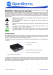
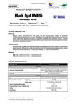
Operating instructions Switching amplifiers 80009130 / 00 02 / 2014 N00..A N05..A UK Instructions for the safe use in hazardous areas 1 Use • Units which contain intrinsically safe circuits are used to operate intrinsically safe field units within hazardous areas. • The manufacturer's data sheets must be observed. • The units are not suitable for the separation of signals in power measurement technology. • The laws and regulations applicable to the use or intended application must be adhered to. 2 Mounting In principle two different types of mounting are possible: 1. Mounting on 35mm rail (the units are clipped onto the rail). 2. Wall mounting (pull out 2 tabs at the bottom of the unit, then fix the unit with 4mm screws). 3 Setup, installation • The units have the protection rating IP20 in accordance with EN 60529 and must therefore be protected accordingly when exposed to adverse environmental conditions such as water splashes or dirt exceeding the soiling degree 2. • The units must be mounted outside the hazardous area! • For units with intrinsically safe circuits the protected circuit (light blue marking on the unit) may be connected into hazardous areas. Special care must be taken for a safe separation from all non intrinsically safe circuits. The intrinsically safe circuits must be installed in accordance with the applicable installation regulations. • For the connection of the intrinsically safe field units to the intrinsically safe circuits of the switching amplifiers the relevant maximum values of the field unit and the switching amplifier according to the explosion protection must be observed (proof of intrinsic safety). • When the intrinsically safe circuits are used in hazardous dust areas "D" only certified field units are allowed to be connected. 2 The EC certificates of conformity and EC type test certificates must be adhered to. Compliance with the "Special Conditions" which may be included therein is especially important. 4 Maintenance, repair The transmission characteristics of the units are stable over long periods, regular adjustment or such like is therefore not necessary. No maintenance is required. 5 Rectification of faults Units that are operated in combination with hazardous areas must not be modified. UK Only specially qualified and authorised personnel are allowed to repair the unit. Insulation coordination for units with Ex certificate in accordance with EN 60079-11: The units are rated for use in soiling degree 2 in accordance with DIN EN 50178. 3 Ι ΙΙ Ι ΙΙ 1: LEDs yellow Indication of the switching status output 1 / output 2; lights when the corresponding output is switched / the relay is energised. 2: LEDs red Fault indication for input circuit 1 / input circuit 2; lights in case of wire break or short circuit in the respective input circuit. The corresponding output is not active (transistor blocked, relay de-energised). 3: LED green Lights when supply voltage is applied. 4: Selector switch Programming of the output function S1 S1 / S2 = 1: direct operation 5: Selector switch (output switches like input signal: IN = ON → OUT = ON). S1 / S2 = 2: inverted operation (output switches opposed to the input S2 signal: IN = ON → OUT = OFF). For single-channel units S2 has no function. 6: Selector switch Setting for short circuit / wire monitoring S3 •When proximity switches are connected monitoring is always active. S3 must be in position I. •When mechanical switches are connected the following applies: -- Monitoring active for input circuit no. 1, S3 must be in position I. -- Without short circuit monitoring for input circuit no. 2 and S3 in position Ι. -- Without short circuit and wire monitoring for input circuit no. 3 and S3 in position ΙΙ. 4 6 Wiring Namur switches 1 Mechanical switches input circuit no. 2 400 Ω ≤ R ≤ 2 kΩ 3 10 kΩ 10 kΩ 1 2 3 1 2 3 1 2 3 1 2 3 4 5 6 4 5 6 4 5 6 4 5 6 UK 7 Type test certificate / Electrical values Article no. Type test certificate N0030A N0031A N0032A N0033A PTB 02 ATEX 2035 N0530A N0533A PTB 02 ATEX 2036 N0531A N0532A N0534A PTB 02 ATEX 2037 Max. permissible values of the control circuits in type of protection intrinsic safety Ex ia IIC / IIB Ex ib IIC / IIB Voltage: 10.6 V Current: 19.1 mA Power: 51 mW External inductance: 97 mH (IIC) / 390 mH (IIB) External capacitance: 2.32 µF (IIC) / 16.2 µF (IIB) Voltage: 10.5 V Current: 13 mA Power: 34 mW External inductance: 210 mH (IIC) / 840 mH (IIB) External capacitance: 2.41 µF (IIC) / 16.8 µF (IIB) Voltage: 10.5 V Current: 13 mA Power: 34 mW External inductance: 200 mH (IIC) / 740 mH (IIB) External capacitance: 2.4 µF (IIC) / 16.8 µF (IIB) Marking II (1) G [Ex ia] IIC II (1) D [Ex ia] IIIC 5