1
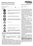
81700705
•
•
Classic Solar EnerSol, EnerSol T, OPzS Solar
Operating Instructions
for stationary lead acid batteries
Nominal data
• Nominal voltage UN
• Nominal capacity CN = C100 or C120
• Nominal discharge current IN = I100 or I120
• Final discharge voltage Uf
• Nominal temperature TN
:
:
:
:
:
Battery type:
Number of cells/blocks:
Assembly by:
Exide Technologies order no.:
2.0 V x number of cells
120 h discharge (see type plate and technical data in these instructions)
I100 = C100 / 100 h or I120 = C120 120 h
see technical data in these instructions
25° C
Commissioned by:
date:
Security signs attached by:
date:
Observe these Instructions and keep them located near the battery for future
reference!
Work on the battery should only be carried out by qualified personnel.
•
•
Do not smoke!
Do not use any naked flame or other sources of ignition.
Risk of explosion and fire!
•
•
While working on batteries wear protective goggles and clothing!
Observe the accident prevention rules as well as EN 50272-2,
EN 50110-1!
•
Any acid splashes on the skin or in the eyes must be rinsed with plenty of
clean water immediately. Then seek medical assistance.
Spillages on clothing should be rinsed out with water!
•
•
Explosion and fire hazard, avoid short circuits.
Avoid electrostatic charges and discharges/sparks!
•
Electolyte is strongly corrosive!
•
Blocks/cells are very heavy! Make sure they are installed securely! Only use
suitable means of transport!
Block/cell containers are sensitive to mechanical damage.
Handle with care!
•
•
•
•
Caution! Dangerous voltage.
Metal parts of the battery are always alive, therefore do not place
items or tools on the battery!
Non-compliance with operating instructions and installations or repairs made with other than
original accessories and spare parts or with accessories and spare parts not recommended
by the battery manufacturer or repairs made without authorization and use of additives for
the electrolytes (alleged enhancing agents) render the warranty void.
Pb
Spent batteries have to be collected and recycled separately from normal household
wastes (EWC 160601). The handling of spent batteries is described in the EU Battery
Directive (2006/66/EC) and their national transitions (UK: HS Regulation 1994 No. 232,
Ireland: Statory Instrument No. 73/2000). Contact your supplier to agree upon the
recollection and recycling of your spent batteries or contact a local and authorized
Waste Management Company.
1. Start Up
Check all cells/blocks for mechanical damage,
correct polarity and firmly seated connectors.
The following torques apply to the cell types:
Ener Sol
A-Pol
8 Nm ± 1
date:
EnerSol T
(M 10)
25 Nm ±1
OPzS Solar
(M 8)
20 Nm ± 1
Put on the terminal covers if necessary. Check
the electrolyte level in all cells and if necessary
top up to maximum level with purified water acc.
to DIN 43530 Part 4. Connect the battery with
the correct polarity to the charger (pos. pole to
pos. terminal). The charger must not be switched
on during this process, and the load must not be
connected. Switch on charger and start charging
following acc. to 2.2.
If there is only an alternative source of energy
available, then the battery must be charged until
the cell voltage is the same in all cells and the
electrolyte density has reached the nominal
value (see technical data). The loads must be
switched off during charging. The insulation resistance measured at the disconnected loads and
charger should be ≥ 100 Ω per volt nominal voltage.
2. Operation
For the installation and operation of stationary
batteries EN 50 272-2 is mandatory.
The battery should always be operated using a
charge controller and deep discharge protection.
The battery must be installed so that it is not in
direct sunlight and in a way which prevents
ambiance-dependent temperature differences of
> 3 K arising. The spacing between the cells or
blocs should be 10 mm and at least 5 mm in rack
mounting.
2.1 Discharge
Discharge must not be continued below the voltage recommended for the discharge time.
Deeper discharges must not be carried out.
Discharge should not exceed the nominal capacity. Unless otherwise indicated by the manufacturer.
Recharge immediately following complete or
partial discharge. A battery is regarded as discharged when the electrolyte density is < 1.13
kg/l at 25° C. This corresponds to a discharge
level of ca. 80% of the nominal value. An electrolyte density of < 1.13 kg/l is a deep discharge.
Deep discharge reduces the lifetime of the battery.
2.2 Charging
a) using an external charger
All charging characteristics with their specific
data, described in
DIN 41773 (IU-characteristic; I-const.: ± 2%;
U-const.: ± 1%)
DIN 41774 (W-characteristic; ± 0.05 Vpc)
DIN 41776 (I-characteristic; I-const.: ± 2%)
may be used. Depending on to the charging
equipment, specification and characteristics,
alternating currents flow through the battery
superimposing onto the direct current during
charge operation.
Alternating currents and the reaction from the
loads may lead to an additional temperature
increase of the battery, and strain the electrodes
causing possible damage (see point 2.5), which
can shorten the battery life.
When charging with an external charger, the battery is disconnected from the load. The temperature must be monitored. Towards the end of
the charging process the charge voltage of the
battery is 2.6 V - 2.75 V times the number of
cells. The charging process must be monitored
(see points 2.4, 2.5 and 2.6)! On reaching a fully
charged state, the charging process must be
stopped or switched to the float charge voltage
as in table 1. For charge current see point 2.6.
b) with alternative power supply
When using power supply units with solar modules or wind generators, the battery charger is not
able to supply the maximum load current at all
times. The load current intermittently exceeds
the nominal current of the battery charger.
During this period the battery supplies power.
This results in the battery not being fully charged
at all times. Therefore, depending on the load the
charge voltage must be set at 2.23 V - 2.35 V x
number of cells. This has to be carried out in
accordance with the manufacturers instructions.
Recommended charge voltage for cyclical application:
Depending on the depth of discharge and the
load the charge voltage is adjusted according to
the specified values on table 1.
Charging
procedure
IU-characteristic
I-characteristic
W-characteristic
Range
EnerSol
EnerSol T
OPzS Solar
Charge voltage [Vpc]
2.32 - 2.40
2.30 - 2.40
2.28 - 2.40
Table 1: Recommended charge voltage for cyclical
application
The charge voltage has to be adjusted to reach
the nominal value ± 0.01 kg/l (see technical data)
once a month. If this is not the case, it is necessary to increase the recommended charge voltage
stepwise by approximately 20 mVpc to a maximum of 2.40 Vpc according to table 1 or carry
out an equalizing charge acc. to 2.4 every month.
2.3 Maintaining full charge
(float charging)
The devices used must comply with the stipulations under DIN 41773. They are to be set so that
the average cell voltage is as in table 2 and the
electrolyte density should not decrease over a
lengthy period, if necessary the charge voltage
Range
EnerSol
EnerSol T
OPzS Solar
Float charge voltage [Vpc]
2.27
2.25
2.23
Table 2: Float charge voltage
must be increased acc. to table 1.
2.4 Equalizing charge
Because it is possible to exceed the permitted
load voltages, appropriate measures must be
taken, e.g. switch off the load.
Equalizing charges are required after deep discharges and/or inadequate charges.
They can be carried out as follows:
a) Using alternative form of power supply
– at constant voltage of max. 2.4 Vpc up to
72 hours (the number of hours increases
with less charging current acc.to table 3).
b) Using an external charger
– at constant voltage of max. 2.4 Vpc up to
72 hours
– with I- or W-characteristic as in point 2.6.
The electrolyte temperature must never exceed
55° C. If it does, stop charging or revert to float
charge to allow the temperature to drop.
The end of the equalizing charge is reached
when the electrolyte density and the cell voltages no longer increase over a period of 2 hours
(2 h-criterion only applies to I- and W-characteristics).
2.5 Alternating currents
When recharging or boost charging up to 2.4
Vpc under operation modes 2.2 the value of the
alternating current is occasionally permitted to
reach 10 A per 100 Ah C10.
In a fully charged state during float charge or
standby parallel operation the value of the alternating current must not exceed 5 A per 100 Ah
C10.
2.6 Charging currents
When charging with the IU-characteristic, the
charging current should be 10 A to 35 A / 100 Ah
C10 (reference values).
Exceeding this voltage of 2.4 Vpc increases
water decomposition. Charging in cyclical application generates more heat. For that reason the
charging currents shown in the following table 3
must not be exceeded.
Max. charging
current
[A/100 Ah C10]
35
5
7
3.5
Charging
voltage
[Vpc]
2.40
2.60 - 2.75
at 2.40
at 2.65
Table 3: Maximal charging currents with different
characteristics
2.7 Temperature
The recommended operating temperature range
for lead acid batteries is 10° C to 30° C. All technical data apply to the nominal temperature 25° C.
The ideal operating temperature is 25° C ± 5 K.
(OPzS Solar =20° C)
Higher temperatures will seriously reduce service life. Lower temperatures reduce the available
capacity. The absolute maximum temperature is
55° C.
2.8 Temperature-related charge voltage
A temperature related adjustment of the charge
voltage within the operating temperature of 10° C
to 30° C is not necessary. If the operating temperature is constantly outside this range, the
charge voltage has to be adjusted.
The temperature correction factor is -0.004 Vpc
per K. If the temperature is constantly in excess
of 40° C, the factor is -0.003 Vpc per K.
2.9 Electrolyte
The electrolyte is diluted sulphuric acid. The
nominal electrolyte density ± 0.01 kg/l (acc. to
technical data) is based on 25° C when fully
charged and with the maximum electrolyte level.
Higher temperatures reduce electrolyte density,
lower temperatures increase electrolyte density.
The appropriate correction factor is - 0.0007 kg/l
per K.
Example: electrolyte density of 1.23 kg/l at 40° C
corresponds to a density of 1.24 kg/l at 25° C or
an electrolyte density of 1.25 kg/l at 10° C corresponds to a density of 1.24 kg/l at 25° C.
3. Battery maintenance and control
The electrolyte level must be checked regularly.
If it drops to the lower electrolyte level mark,
purified water must be added in accordance with
DIN 43530 Part 4 (maximum conductivity 30
µS/cm). Keep the battery clean and dry to avoid
leakage currents. Plastic parts of the battery,
especially containers, must be cleaned with
clean water without additives.
Monthly measurements and recording:
• Battery voltage
• Voltage of some cells/block batteries
• Electrolyte temperature of some cells
• Battery-room temperature
• Electrolyte density of some cells
It is necessary to carry out an equalizing charge
acc. to 2.4 if the cell/block average float charge
voltages (see table 2) differ more than those in
table 4 below and/or if the electrolyte density of
the cells of a battery string deviates from the
average-value more than ± 0.01 kg/l.
Tolerance
2 V-Cell
6 V-Block
12 V-Block
+
0.10 V
0.17 V
0.24 V
–
0.05 V
0.09 V
0.12 V
Table 4
Annual measurements and recording:
• Voltage of all cells/block batteries
• Electrolyte temperature of all cells
• Electrolyte density of all cells
Annual visual check:
• Screw connections
• Screw connections without locking devices
have to be checked for tightness
• Battery installation and arrangement
• Ventilation the battery room
4. Tests
Tests have to be carried out according to
IEC 60896-11 and DIN 43539 Part1. Special
instructions like VDE 0107 and EN 50172 have
to be observed.
5. Faults
Call the service agents immediately if faults in
the battery or charging unit are found. Recorded
data as described in point 3 simplify the troubleshooting and fault clearance. A service contract
for example with Exide Technologies facilitates
detecting faults in time.
6. Storage and taking out of operation
To store or decommission cells/blocs for a longer period of time, they should be fully charged
and stored in a dry and cold but frost-free room,
away from direct sunlight. To avoid damage, the
following charging methods can be chosen:
1. Equalizing charges every three months as
described under point 2.4.
At average ambient temperatures of more
than the nominal temperature shorter intervals can be necessary.
2. Float charging as under point 2.3.
7. Transport
To prevent any leakage of electrolyte, the cells/
block batteries must be transported in an upright
position. Cells/block batteries without any visible
damage are not defined as hazardous goods
under the regulations for transport of hazardous
goods by road (ADR) or by rail (RID). They must
be protected against short circuits, slipping,
upsetting or damaging. Bloc batteries may be
suitably stacked and secured on pallets (ADR
and RID, special provision 598). It is prohibited
to stack pallets. No dangerous traces of acid
may be found on the exteriors of the packing
units. Cells/bloc batteries whose cases leak or
are damaged must be packed and transported
as class 8 hazardous goods under UN no. 2794.
8. Technical data
The nominal voltage, the number of cells, the
nominal capacity (C100 or C120 = CN) and the battery type are described on the type plates. See
table 8.1.1 - 8.1.3 other capacities at different
discharge currents with the corresponding
discharge times.
8.1
Measurements, weights and capacities (Cn) at different discharge times (tn) and final discharge voltage (Uf)
8.1.1 Stationary lead acid bloc batteries type EnerSol
with positive and negative grid plates, Nominal electrolyte density 1.28 kg/l
Discharge data
Capacity [Ah]
Discharge time
[h]
Final discharge
voltage [Vpc]
EnerSol
50
EnerSol
65
EnerSol
80
EnerSol
100
EnerSol
130
EnerSol
175
EnerSol
250
1)
Discharge current [A]
120
100
120
100
1.85
1.85
1.85
1.85
53
66
80
99
132
179
256
52
65
78
97
130
175
250
0.44
0.55
0.67
0.83
1.10
1.49
2.13
0.52
0.65
0.78
0.97
1.30
1.75
2.50
Length
max.
[mm]
210
242
278
353
349
513
518
Measurements and weights
Width
Height 1) Weight
max.
max.
including
acid
approx.
[mm]
[mm]
[kg]
175
190
13.7
175
190
17.3
175
190
20.7
175
190
26.4
175
290
33.0
223
223
47.8
276
242
63.0
Weight
acid
approx
[kg]
2.1
2.7
4.7
7.0
10.9
14.6
18.6
The above mentioned height can differ depending on the used vents
8.1.2 Stationary lead acid cells type EnerSol T
with positive and negative grid plates, Nominal electrolyte density 1.26 kg/l
Discharge data
Capacity [Ah]
Discharge time
[h]
Final discharge
voltage [V]
EnerSol T
370
EnerSol T
460
EnerSol T
550
EnerSol T
650
EnerSol T
760
EnerSol T
880
EnerSol T
1000
EnerSol T
1130
EnerSol T
1250
1)
Discharge current [A]
120
48
24
10
120
48
24
10
1.85
1.80
1.80
1.80
1.85
1.80
1.80
1.80
367
452
542
668
779
897
1025
1154
1282
361
437
524
656
766
854
1008
1134
1260
333
416
499
625
729
840
960
1080
1200
280
350
425
527
615
714
809
910
1011
3.06
3.77
4.52
5.57
6.49
7.48
8.54
9.62
10.68
7.52
9.10
10.92
13.67
15.96
17.79
21.00
23.63
26.25
13.88
17.33
20.79
26.04
30.38
35.00
40.00
45.00
50.00
28.0
35.0
42.5
52.7
61.5
71.4
80.9
91.0
101.1
The above mentioned height can differ depending on the used vents
Length
max.
[mm]
83
101
119
119
137
137
155
173
191
Measurements and Weights
Width
Height 1) Weight
Weight
max.
max.
including
acid
acid
approx. approx.
[mm]
[mm]
[kg]
[kg]
198.5
445
17.3
5.1
198.5
445
21.0
6.3
198.5
445
24.7
7.5
198.5
508
29.5
8.6
198.5
508
31.0
10.0
198.5
556
38.0
11.0
198.5
556
43.1
12.6
198.5
556
47.7
14.1
198.5
556
52.8
15.6
8.1.3 Stationary lead acid bloc batteries type OPzS Solar bloc batteries and single cells
with positive tubular plates and negative grid plates, Nominal electrolyte density 1.24 kg/l
Bloc battery
Discharge data
Capacity [Ah]
12V
12V
12V
6V
6V
6V
Discharge time
[h]
Final discharge
voltage [V]
OPzS Solar
OPzS Solar
OPzS Solar
OPzS Solar
OPzS Solar
OPzS Solar
Discharge current [A]
Length
max.
120
48
24
10
120
48
24
10
1.85
1.80
1.80
1.80
1.85
1.80
1.80
1.80
70
140
210
280
350
420
82.7
139.0
210.0
294.0
364.0
417.0
78.4
141.0
200.0
296.0
374.0
420.0
69.4
118.0
177.0
250.0
311.0
354.0
51.5
103.0
154.0
206.0
257.0
309.0
0.7
1.2
1.8
2.5
3.0
3.5
1.6
2.9
4.2
6.2
7.8
8.8
2.9
4.9
7.0
10.5
13.0
14.8
5.2
10.3
15.5
20.6
25.8
30.9
[mm]
275
275
383
275
383
383
190
245
305
380
450
550
660
765
985
1080
1320
1410
1650
1990
2350
2500
3100
3350
3850
4100
4600
190
245
305
380
450
550
660
765
985
1080
1320
1410
1650
1990
2350
2500
3100
3350
3850
4100
4600
165
215
270
330
395
480
575
670
860
940
1150
1225
1440
1730
2090
2215
2755
2985
3430
3650
4100
145.0
190.0
240.0
300.0
355.0
430.0
515.0
600.0
770
845
1030
1105
1290
1550
1910
2015
2520
2740
3135
3355
3765
132.0
173.0
220.0
273.0
325.0
391
469
546
700
773
937
1009
1174
1411
1751
1854
2318
2524
2884
3090
3451
1.6
2.0
2.5
3.2
3.8
4.6
5.5
6.4
8.2
9.0
11.0
11.8
13.8
16.6
19.6
20.8
25.8
27.9
32.1
34.2
38.3
3.4
4.5
5.6
6.9
8.2
10.0
12.0
14.0
17.9
19.6
24.0
25.5
30.0
36.0
43.5
46.1
57.4
62.2
71.5
76.0
85.4
6.0
7.9
10.0
12.5
14.8
17.9
21.5
25.0
32.1
35.2
42.9
46.0
53.8
64.6
79.6
84.0
105.0
114.2
130.6
139.8
156.9
13.2
17.3
22.0
27.3
32.5
39.1
46.9
54.6
70.0
77.3
93.7
100.9
117.4
141.1
175.1
185.4
231.8
252.4
288.4
309.0
345.1
105
105
105
126
147
126
147
168
147
147
215
215
215
215
215
215
215
215
215
215
215
Measurements and Weights
Width
Height 1) Weight
Weight
max.
max.
including
acid
acid
approx. approx.
[mm]
[mm]
[kg]
[kg]
208
385
35
15
208
385
45
14
208
385
64
19
208
385
41
13
208
385
56
20
208
385
63
20
1)
The above mentioned height can differ depending on the used vents
Exide Technologies GmbH
Im Thiergarten
63654 Büdingen – Germany
Tel.: +49 (0) 60 42 / 81 544
Fax: +49 (0) 60 42 / 81 398
www.industrialenergy.exide.com
208
208
208
208
208
208
208
208
208
208
193
193
235
277
277
277
400
400
490
490
580
405
405
405
405
405
520
520
520
695
695
695
695
695
695
845
845
815
815
815
815
815
13.7
15.2
16.6
20.0
23.3
26.7
31.0
35.4
43.9
47.2
59.9
63.4
73.2
86.4
108.0
114.0
151.0
158.0
184.0
191.0
217.0
5.2
5.0
4.6
5.8
6.9
8.1
9.3
10.8
13.0
12.8
17.1
16.8
21.7
26.1
33.7
32.7
50.0
48.0
60.0
58.0
71.0
81700705 0,5 III.09
OPzS Solar
OPzS Solar
OPzS Solar
OPzS Solar
OPzS Solar
OPzS Solar
OPzS Solar
OPzS Solar
OPzS Solar
OPzS Solar
OPzS Solar
OPzS Solar
OPzS Solar
OPzS Solar
OPzS Solar
OPzS Solar
OPzS Solar
OPzS Solar
OPzS Solar
OPzS Solar
OPzS Solar
NXCSLOEPDF00710 · Druckhaus Bechstein · Printed in Germany · Subject to change without prior notice
Single cell